EP3627661A1 - Induit à cage d'ecureuil et fabrication d'un induit à cage d'ecureuil - Google Patents
Induit à cage d'ecureuil et fabrication d'un induit à cage d'ecureuil Download PDFInfo
- Publication number
- EP3627661A1 EP3627661A1 EP18196050.1A EP18196050A EP3627661A1 EP 3627661 A1 EP3627661 A1 EP 3627661A1 EP 18196050 A EP18196050 A EP 18196050A EP 3627661 A1 EP3627661 A1 EP 3627661A1
- Authority
- EP
- European Patent Office
- Prior art keywords
- base body
- recesses
- conductive base
- magnetically conductive
- short
- Prior art date
- Legal status (The legal status is an assumption and is not a legal conclusion. Google has not performed a legal analysis and makes no representation as to the accuracy of the status listed.)
- Granted
Links
Images


Classifications
-
- H—ELECTRICITY
- H02—GENERATION; CONVERSION OR DISTRIBUTION OF ELECTRIC POWER
- H02K—DYNAMO-ELECTRIC MACHINES
- H02K15/00—Processes or apparatus specially adapted for manufacturing, assembling, maintaining or repairing of dynamo-electric machines
- H02K15/02—Processes or apparatus specially adapted for manufacturing, assembling, maintaining or repairing of dynamo-electric machines of stator or rotor bodies
- H02K15/021—Magnetic cores
- H02K15/023—Cage rotors
-
- H—ELECTRICITY
- H02—GENERATION; CONVERSION OR DISTRIBUTION OF ELECTRIC POWER
- H02K—DYNAMO-ELECTRIC MACHINES
- H02K1/00—Details of the magnetic circuit
- H02K1/06—Details of the magnetic circuit characterised by the shape, form or construction
- H02K1/22—Rotating parts of the magnetic circuit
- H02K1/26—Rotor cores with slots for windings
- H02K1/265—Shape, form or location of the slots
-
- H—ELECTRICITY
- H02—GENERATION; CONVERSION OR DISTRIBUTION OF ELECTRIC POWER
- H02K—DYNAMO-ELECTRIC MACHINES
- H02K15/00—Processes or apparatus specially adapted for manufacturing, assembling, maintaining or repairing of dynamo-electric machines
- H02K15/20—Shaping or compacting conductors or winding heads after the installation of the winding in the cores or machines; Applying fastening means on winding heads
- H02K15/22—Shaping or compacting conductors in slots or around salient poles
-
- H—ELECTRICITY
- H02—GENERATION; CONVERSION OR DISTRIBUTION OF ELECTRIC POWER
- H02K—DYNAMO-ELECTRIC MACHINES
- H02K17/00—Asynchronous induction motors; Asynchronous induction generators
- H02K17/02—Asynchronous induction motors
- H02K17/16—Asynchronous induction motors having rotors with internally short-circuited windings, e.g. cage rotors
- H02K17/168—Asynchronous induction motors having rotors with internally short-circuited windings, e.g. cage rotors having single-cage rotors
-
- H—ELECTRICITY
- H02—GENERATION; CONVERSION OR DISTRIBUTION OF ELECTRIC POWER
- H02K—DYNAMO-ELECTRIC MACHINES
- H02K3/00—Details of windings
- H02K3/46—Fastening of windings on the stator or rotor structure
- H02K3/48—Fastening of windings on the stator or rotor structure in slots
Definitions
- the invention relates to a squirrel-cage rotor, the production of a squirrel-cage rotor and a dynamoelectric rotary machine with such a squirrel-cage rotor and the use of such machines.
- Dynamoelectric rotary machines with a squirrel-cage rotor are referred to as asynchronous machines, the squirrel-cage rotor consisting of conductors arranged in grooves in a laminated core, each of which is electrically short-circuited by a short-circuit ring on the respective end faces of the laminated core.
- the hybrid runners described here are compared to cage runners that are designed as pure copper runners, among others. can only be used to a limited extent due to their comparatively lower energy efficiency.
- the hybrid rotor casting technology known, inter alia, in the documents listed has been carried out on the conductors so that the groove, in particular the cross section of the groove of the cage rotor in the laminated core, was only partially occupied by a copper insert. The remaining cross-section was required as a pouring channel for the supply between the two short-circuit rings and was filled with aluminum.
- the electrical design of the cage rotor is determined, among other things, by the degree of filling of the groove with copper.
- a high degree of filling is electrically advantageous, but is therefore better than that previously known Manufacturing technology of hybrid rotor casting. This requires a sufficiently large remaining cross section in the groove in order to bring the molten aluminum from one side, the sprue side of the one short-circuit ring, to the other side, the venting side of the second short-circuit ring.
- dynamoelectric machine Relevant for the electrical design of the dynamoelectric machine include the groove's scattering ridges, which face the air gap of the machine, but which are not feasible due to the previous manufacturing process for hybrid rotors, since the laminated core of the rotor groove must be closed in the circumferential direction in order to prevent liquid aluminum from escaping during production.
- a further disadvantage is that a conductor bar or short-circuit bar is only cooled by a punctiform support of the bar on the walls of the groove. If the aluminum shrinks in the area of the groove, this also leads to the formation of gaps, which does not allow reliable cooling of the conductor material from the groove in the laminated core.
- a mechanical fixation of the rod or the copper insert within the groove and in the middle of the laminated core is also indefinite for the reason stated above.
- the object of the invention is to create a squirrel-cage rotor of an asynchronous machine which avoids the disadvantages mentioned above.
- the invention is also based on the object of providing a comparatively economical method for producing a cage rotor. Furthermore, the starting behavior of this rotor should be reliably adjustable.
- the problem is also solved by a dynamoelectric machine with a squirrel-cage rotor according to the invention produced by one of the methods according to the invention.
- a conductor made of a first electrically conductive material in a predetermined shape in particular a copper conductor rod, is now axially inserted and / or fixed and / or fixed in a first recess in the magnetically conductive base body, for example an axially packaged laminated core of the cage rotor / or positioned.
- Only one conductor material is provided in the first recesses of the cage rotor. This is, in particular, a prefabricated copper conductor bar. Material contamination of the conductor material or oxide layers are to be subsumed under the conductor material.
- the first recess is preferably designed as a groove with a groove slot facing an air gap of the dynamoelectric machine.
- This slot is used in the operation of a dynamoelectric machine, among other things. decisive for the start-up behavior of the machine and the start-up or operating current, as through the slot, among other things. the scattering reactivity of the runner is influenced.
- a magnet is used on the front sides of the magnetically conductive base body cast on second electrically conductive material short-circuit rings, which are either spaced from the end faces or rest directly on the end faces.
- the short-circuit rings are formed by means of tools provided for this purpose and, if necessary, further special second recesses in the magnetically conductive base body of the cage rotor, in particular by means of pouring channels which transport a second electrically conductive material from one side of the conductive base body to the other side in the liquid state.
- this filler material that is to say the second electrically conductive material
- short-circuit rings are now formed on the axial end faces of the cage rotor.
- the pouring channel or filling channel if present, is filled with the filling material, for example the molten aluminum, which has then hardened.
- the first conductor material is prefabricated in the form of a bar.
- a rod is provided for each first recess.
- the groove is thus a groove space which is essentially occupied by the first conductor material and - if present - a slot slot.
- the groove space is limited by a groove wall, a groove base and, if present, a groove slot.
- the first conductor material is located in the slot space and, to a small extent, may still be in the slot.
- the groove Due to the manufacturing process according to the invention with a special pouring channel or also without, the groove can now be carried out with a spreading web and can thus, among other things. regardless of the design of the pouring channel. There are therefore no restrictions on the copper fill factor of a groove.
- the cross-sectional area and cross-sectional shape of the conductor bar or the conductor bars of a first recess essentially correspond to the groove space.
- the requirements with regard to the start-up data, such as torque or starting current, can only be realized and defined within the framework of the geometric manufacturing conditions.
- the slot slots are considered in cross-section, among others. parallel-flanked or V-shaped.
- the slot is usually parallel flanked and / or in the radial center of the groove.
- the slot slot can also or instead, viewed radially, run obliquely and / or be arranged eccentrically with respect to the radial center of the slot.
- the dynamoelectric machine By caulking the prefabricated rod, or conductor rod or conductor in the groove, plastic deformation of this rod is now brought about in the groove space, which leads to a positive connection of this rod to the wall of the groove space, i.e. the inside. Due to the larger contact surfaces of the groove wall and conductor bar and the more uniform and better heat dissipation compared to a point contact, the dynamoelectric machine also achieves better operating behavior.
- a positive connection between the conductor bar and groove wall is brought about, which is generated, for example, by driving a chisel into the conductor bar positioned in the groove space by means of one or more slots.
- the chisel is placed over the slot on the conductor bar.
- heating the magnetically conductive base body that is to say the laminated core, is also suitable for closed slots and slots with a slot slot.
- the conductor bars are fixed in the first recesses, which likewise leads to a positive connection between the groove wall and the respective conductor bars.
- this heating of the magnetically conductive base body that is to say the laminated core, can be advantageous for the casting process, since the heating, the second electrically conductive material to be led through the pouring channel cools less quickly.
- the further recesses in the squirrel-cage rotor which run essentially axially parallel, like the second, third and fourth recesses, are designed to be closed when viewed in the circumferential direction.
- the fourth recess is a shaft bore into which a shaft can be positioned in a rotationally fixed manner after the cage rotor has been completed.
- the third recesses which can be distributed almost arbitrarily around the axis, form axially extending cooling channels, which can optionally be connected to a cooling circuit of the dynamoelectric machine.
- the second recesses are, in particular, pouring channels through which the filling material, the second electrically conductive material, passes from one axial end to the other axial end of the cage rotor in the manufacturing process. This is primarily liquid aluminum.
- the electrical conductivity of the first conductor material and the second electrically conductive material are different. Their melting temperatures are also different, so that the material with a lower melting point is cast.
- the first conductor material is advantageously made of copper, preferably prefabricated copper rods, and the second electrically conductive material is aluminum.
- the squirrel-cage rotor according to the invention definitely requires first recesses and a fourth recess for its production, the second and third recesses are optional and are used, among other things. according to the type of manufacture, place of use and / or operating cycles of the dynamoelectric machine, both in terms of their shape, number and radial arrangement within the cage rotor.
- the manufacturing process of such a squirrel-cage rotor can take place from one side, that is to say from one axial end of the squirrel-cage rotor to the other, in which the second is electrically conductive Material, for example liquid aluminum, enters a filling space of a first tool and from there pours axially over the pouring channels to the other axial end of the cage rotor and forms the second short-circuit ring there.
- the second is electrically conductive Material, for example liquid aluminum
- Another possibility of designing such a squirrel-cage rotor is, after the conductor bars have been inserted and / or fixed in the groove, to cast the short-circuit rings simultaneously or in succession only at the axial ends of the squirrel-cage rotor.
- the short-circuit rings are thus cast separately or in succession using suitable tools or devices, without the need for casting channels in the magnetically conductive base body.
- the tools or casting devices are filled, for example, with liquid aluminum, whereby the different materials of the short-circuit ring and the conductor bars, in particular the predetermined sections protruding from the magnetically conductive base body, are brought into electrical contact.
- Slanting of the axis or slight oscillations around the axis of the magnetically conductive base body, for example a laminated core supports final gassing during the casting process, so that the formation of lunches is suppressed.
- the electrical and / or mechanical connection between the conductor bars and the short-circuit rings can be improved in that the different materials of the conductor bar and short-circuit ring enter into a mixed-crystalline connection, in particular at their predeterminable contact points.
- the conductor bars protrude axially from both ends of the laminated core of the rotor and into the cast-on short-circuit rings.
- the conductor bars are bound to the die casting in the short-circuit ring by the maximum possible binding forces. Accordingly, the connection between the conductor bars and the short-circuit rings remains stable in spite of different thermal expansion coefficients of the different materials in the axial and radial directions even when the squirrel-cage rotor undergoes pronounced thermal cycles during operation of the dynamoelectric machine.
- This alloy can also be used to create an optimal electrical transition conductance between the materials of the short-circuit ring and conductor bar.
- the first alloy layer is produced, for example, by electromechanical electroplating.
- a layer of the coating material is first deposited electrochemically, in particular on predetermined sections of the conductors, in particular the conductor bars.
- the desired mixed crystalline connection is created between the conductor and the coating material. Due to the die-casting process, this coating melts on the conductors and also forms a mixed-crystalline compound with the pressure melt, so that a second alloy layer is created.
- An embodiment is advantageous in which the coating and the first alloy layer are produced by a thermal spraying process, in particular flame spraying, plasma spraying, arc spraying or laser spraying.
- the coating and the first alloy layer are produced by cold gas spraying.
- the coating and the first alloy layer are produced by vapor deposition.
- an oxide layer is advantageously removed from the conductors by chemical pretreatment of the conductors before coating.
- An oxide layer has insulating electrical properties, so that the contact resistance between the first and the second material is significantly reduced by removing said oxide layer.
- the said end regions of the conductor bars represent the critical connection point between the conductors and the short-circuit rings. Accordingly, the strong crystalline connection is particularly important here. Especially in this end area of each conductor, the electrical transition conductance between the two materials is of particular importance because the current flow from the conductors to the short-circuit rings.
- connection between the conductors and the short-circuit rings can be strengthened alternatively or additionally by the conductors at both ends having an end region protruding from the rotor laminated core and into the short-circuit rings with positive-locking means for producing a positive connection between the conductors and have the cast short-circuit rings.
- the form-locking means used prevent the conductors from shifting within the short-circuit rings or pulling the conductor bars out of the short-circuit rings, as a result of which a tear at the joint or at the contact surfaces between the two materials can be avoided.
- At least one end region of a conductor bar has no larger cross-sectional areas and shape than the conductor bar itself.
- the short-shot rings can provide means for absorbing centrifugal force on their radially outer edge, e.g. a cuff or ring made of high-strength material.
- electrically conductive inserts can be positioned, which are then cast in. This reduces the casting effort and / or the pouring channels can accordingly be dimensioned smaller.
- These inserts can, as described above, be coated and / or are made of the first conductor material or second electrically conductive material or another electrically conductive material.
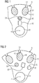
- FIG. 1 shows a layer of a magnetically conductive base body, in particular a laminated core 32 of a cage rotor 9, which shows the first to fourth recesses 28 to 31 in more detail.
- a copper conductor bar 12 is provided in the first recess 28, which is designed as a groove 33 of the cage rotor 9, which is prefabricated, inserted or inserted axially into the first recess 28. It is therefore also referred to as an insert stick.
- a groove slot 13 extends radially outward from this groove or first recess 28 to an air gap 14 of a dynamoelectric machine 1, not shown in this illustration.
- the starting behavior and torque of the squirrel-cage rotor 9 and thus of the dynamoelectric machine 1 can be set via the width and / or radial length of the slot 13. Furthermore, there are second recesses 29 through which the short-circuit ring 10 can be cast on an axial end face 46 of the cage rotor 9, for example by liquid aluminum. This second recess is then designed as a pouring channel 11.
- a third recess 30 Adjacent to this, radially inward extends a third recess 30 which, when the cage rotor 9 is in operation in the dynamoelectric machine 1, functions as an axial cooling channel 16 for air or liquid cooling of the cage rotor 9 and / or the dynamoelectric machine 1 (not shown in any more detail).
- a fourth recess 31 is designed as a shaft bore 15, into which a shaft 3 is later inserted, which is connected in a rotationally fixed manner to the metal sheets or the magnetically conductive base body of the cage rotor 9.
- the necessary flow rates of the die casting processes during manufacture and / or the cooling media during operation of the machine 1 can be specified in principle.
- FIG 2 shows a similar execution as FIG. 1 , however, the arrangement of the second and third recesses 29, 30 shown here, that is to say the pouring channel 11 and the cooling channel 16 with respect to the cross-sectional shape and / or arrangement radially and in the circumferential direction, can be designed as desired in almost any manner.
- These can be angular shapes such as triangles, rectangles or other polygons, as can rounded shapes such as circles or ellipses.
- the arrangement of the second and third recesses 29 and 30 per sheet can be provided as desired using a stamping tool.
- their execution is based on the manufacturing parameters and the desired operating behavior of the machine 1.
- the first recesses 28, viewed over the axial course, can also be provided with a bevel of half to about three groove divisions in order, inter alia, to Avoid ripple moments.
- the second 29 and / or third recess 30 can also be provided with a bevel. However, this increases the flow resistance both during the casting process and during cooling, so that the second 29 and third recesses 30 are more likely to run parallel to the axis 4, with an optionally selectable inclination of the first recesses 28.
- FIG 3 Another representation of the arrangement of the second and third recesses 29, 30 is FIG 3 refer to. It can also be seen that the invention with conductor bars 12 can also be used with closed grooves, as viewed in the circumferential direction, ie without a slot 13.
- the basic arrangement and positioning of the second and third recesses 29, 30 in a sheet metal are, inter alia, determined by mechanical and / or thermal specifications on the cage rotor 9.
- they can lie essentially on a radius, for example alternately arranged or also arranged radially one above the other.
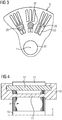
- FIG 4 shows in a basic longitudinal section an illustration of a squirrel-cage rotor 9, the magnetic base body is made of sheet metal.
- Short-circuit rings 10 are arranged adjacent to the end faces 46 on the axial end faces 46 of the laminated core 32 of the cage rotor 9. That is, there are between the inside of the short-circuit ring 10 and the axial end faces 46 of the laminated core 32 of the cage rotor 9 no clearances 37.
- This encapsulation takes place on one side of the squirrel-cage rotor 9 using a direct die-casting method, as will be explained in more detail later, and / or via a pouring channel 11, which forms the short-circuit ring 10 present on the other end face 46 of the squirrel-cage rotor 9.
- the copper rod 12 is further adapted by one or more radial caulking along the slot, the slot shape or the slot space 33.
- Better contact surfaces are thus formed between conductor bar 12, in particular made of copper, and wall 36 of groove space 33, which improve mechanical fixation of the bar in the groove. This is advantageous at high speeds of a dynamoelectric machine 1.
- a comparatively better heat transfer from the copper rod 12 to the laminated core 32 is created. This improves the cooling of the cage rotor 9 and thus the overall operating behavior of the dynamoelectric machine 1.
- FIG 5 shows basically the same execution as FIG 4 , only with additional cooling channels 16, which are arranged radially closer to the axis 4 compared to the pouring channels 11.
- FIG 6 shows in a basic representation an entire dynamoelectric machine 1 with a stator 7 and a winding system which forms winding heads 8 on the end faces of the stator 7.
- the stator 7 is arranged in a housing 2, which is supported on the shaft 3 via end shields 6 or the bearings 5 positioned there.
- the squirrel cage 9 is in this Case according to FIG 4 educated. But he can also according to FIG 5 or FIG 8 be trained.
- a centrifugal force-absorbing element such as e.g. a cuff 47 may be provided.
- This centrifugal force-absorbing element preferably does not protrude radially into the area of the air gap 14 in order not to impair any axial cooling through the air gap 14.
- the short-circuit rings 10 extend radially to the shaft 3. This enables additional heat dissipation from the short-circuit ring 10 into / via the shaft 3. This is particularly advantageous if the shaft 3 itself is cooled, for example by means of a lance cooling system, not shown.
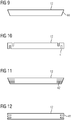
- FIG 7 shows an example of a manufacturing process, wherein the second electrically conductive material 35 in liquid form, such as aluminum, is entered via a tool 18 at an end face of the cage rotor 9 via an inlet opening 26 of the tool 18, forms a short-circuit ring 10 there and via the pouring channel 11 on the other end face 46 forms the second short-circuit ring 10 via the tool 19. Air is additionally emitted from the tools 18, 19 during the casting process via ventilation openings 27.
- the flow directions of the second electrically conductive material 35, such as aluminum, are exemplified by the arrows 21 to 25.
- Another manufacturing method only provides the tools 18, 19 on the end faces 46 of the cage rotor 9.
- the second electrically conductive material 35 (aluminum) for the respective short-circuit rings 10 is cast in simultaneously or in succession via the openings 26, 27. No pouring channels 11 are necessary.
- Another manufacturing method only provides a tool 18 on one end face of the cage rotor 9.
- a short-circuit ring 10 is thus first cast on one end face 46, then the second short-circuit ring 10 is rotated on the second end face 46 by rotating the squirrel-cage rotor 9.
- the tools 18, 19 provide the axially extending slot 13, especially on the end faces 46, with a shut-off element 40 at the transition to the area of the short-circuit ring 10 to be cast, in order to seal and keep the slot 13 free.
- FIG 8 shows a squirrel-cage rotor 9, with short-circuit rings 10, which are at a distance 37 from the end faces 46 of the laminated core. This serves, inter alia, for improved cooling, in particular of the short-circuit rings 10.
- axial cast sections 38 result between the end face of the laminated core and the short-circuit ring 10, which at least during the manufacturing process of the short-circuit rings 10 by suitable devices are bridged so that the cast material, in particular liquid aluminum, can pass from one side to the other side.
- the shape of the axial casting sections 38 is adapted to the shape of the pouring channels 11.
- the axial casting sections 38 can also be designed to be funnel-shaped axially outward in order to simplify the casting process by minimizing flow resistances during the die-casting process.
- these cast sections 38 insofar as they remain at least in part on the squirrel-cage rotor 9, can contribute to active cooling at this distance 37 between the end face 46 and the inside of the short-circuit ring 10.
- these cast sections 38 are shaped like fan blades without impairing the casting process during manufacture.
- the squirrel-cage rotors 9, the pouring channels 11 and possibly also the cast sections 38, as well as the conductors in the grooves 33 are in electrically conductive connection with the short-circuit rings 10.
- FIG 8 for example end sections of the conductor bars 12, which are formed with hole 43 and with hole 43 and slope 44, in order to increase the electrical contact areas between short-circuit ring 10 and conductor bar 12 and / or the mechanical stability between short-circuit ring 10 and conductor bar 12.
- Such squirrel-cage rotors 9 are used in asynchronous machines 1 for low and high voltage.
- the applications range from industrial drives, for example in the food and beverage industry, to traction drives, for example from rail vehicles, trucks, in particular mining trucks, and to pumps, fans and compressors.
- traction drives for example from rail vehicles, trucks, in particular mining trucks, and to pumps, fans and compressors.
- Such asynchronous machines can also be used in machine tools.
Landscapes
- Engineering & Computer Science (AREA)
- Power Engineering (AREA)
- Manufacturing & Machinery (AREA)
- Manufacture Of Motors, Generators (AREA)
- Induction Machinery (AREA)
Priority Applications (1)
| Application Number | Priority Date | Filing Date | Title |
|---|---|---|---|
| EP18196050.1A EP3627661B1 (fr) | 2018-09-21 | 2018-09-21 | Induit à cage d'ecureuil et fabrication d'un induit à cage d'ecureuil |
Applications Claiming Priority (1)
| Application Number | Priority Date | Filing Date | Title |
|---|---|---|---|
| EP18196050.1A EP3627661B1 (fr) | 2018-09-21 | 2018-09-21 | Induit à cage d'ecureuil et fabrication d'un induit à cage d'ecureuil |
Publications (2)
| Publication Number | Publication Date |
|---|---|
| EP3627661A1 true EP3627661A1 (fr) | 2020-03-25 |
| EP3627661B1 EP3627661B1 (fr) | 2021-06-02 |
Family
ID=63678530
Family Applications (1)
| Application Number | Title | Priority Date | Filing Date |
|---|---|---|---|
| EP18196050.1A Active EP3627661B1 (fr) | 2018-09-21 | 2018-09-21 | Induit à cage d'ecureuil et fabrication d'un induit à cage d'ecureuil |
Country Status (1)
| Country | Link |
|---|---|
| EP (1) | EP3627661B1 (fr) |
Citations (8)
| Publication number | Priority date | Publication date | Assignee | Title |
|---|---|---|---|---|
| US6092277A (en) * | 1999-04-28 | 2000-07-25 | General Electric Company | Rotor bar swaging process |
| EP2282396A1 (fr) | 2009-08-03 | 2011-02-09 | Siemens Aktiengesellschaft | Procédé de fabrication pour rotor à cage d'écureuil oblique et rotor à cage d'écureuil oblique |
| EP2299565A1 (fr) * | 2009-09-17 | 2011-03-23 | Siemens Aktiengesellschaft | Rotor d`une machine électrique asynchrone avec moyen de refroidissement |
| WO2012041943A2 (fr) * | 2010-09-30 | 2012-04-05 | Siemens Aktiengesellschaft | Rotor à cage |
| EP2549630A1 (fr) * | 2011-07-22 | 2013-01-23 | Siemens Aktiengesellschaft | Cage d'écureuil d'une machine asynchrone et procédé de fabrication d'une telle cage |
| EP2744089A1 (fr) * | 2012-12-14 | 2014-06-18 | Siemens Aktiengesellschaft | Cage d'écureuil sécurisée |
| EP2953245A1 (fr) * | 2014-06-02 | 2015-12-09 | Siemens Aktiengesellschaft | Induit à cage d'écureuil d'une machine asynchrone |
| EP2891234B1 (fr) | 2012-10-30 | 2016-12-14 | Siemens Aktiengesellschaft | Cage d'écureuil et tige avec une découpe |
-
2018
- 2018-09-21 EP EP18196050.1A patent/EP3627661B1/fr active Active
Patent Citations (9)
| Publication number | Priority date | Publication date | Assignee | Title |
|---|---|---|---|---|
| US6092277A (en) * | 1999-04-28 | 2000-07-25 | General Electric Company | Rotor bar swaging process |
| EP2282396A1 (fr) | 2009-08-03 | 2011-02-09 | Siemens Aktiengesellschaft | Procédé de fabrication pour rotor à cage d'écureuil oblique et rotor à cage d'écureuil oblique |
| EP2299565A1 (fr) * | 2009-09-17 | 2011-03-23 | Siemens Aktiengesellschaft | Rotor d`une machine électrique asynchrone avec moyen de refroidissement |
| WO2012041943A2 (fr) * | 2010-09-30 | 2012-04-05 | Siemens Aktiengesellschaft | Rotor à cage |
| EP2549630A1 (fr) * | 2011-07-22 | 2013-01-23 | Siemens Aktiengesellschaft | Cage d'écureuil d'une machine asynchrone et procédé de fabrication d'une telle cage |
| EP2891234B1 (fr) | 2012-10-30 | 2016-12-14 | Siemens Aktiengesellschaft | Cage d'écureuil et tige avec une découpe |
| EP2744089A1 (fr) * | 2012-12-14 | 2014-06-18 | Siemens Aktiengesellschaft | Cage d'écureuil sécurisée |
| EP2918005B1 (fr) | 2012-12-14 | 2016-06-15 | Siemens Aktiengesellschaft | Cage d'écureuil sécurisée |
| EP2953245A1 (fr) * | 2014-06-02 | 2015-12-09 | Siemens Aktiengesellschaft | Induit à cage d'écureuil d'une machine asynchrone |
Also Published As
| Publication number | Publication date |
|---|---|
| EP3627661B1 (fr) | 2021-06-02 |
Similar Documents
| Publication | Publication Date | Title |
|---|---|---|
| EP2953245B1 (fr) | Induit à cage d'écureuil d'une machine asynchrone | |
| DE102009008440B3 (de) | Käfigläufer | |
| EP2299565B1 (fr) | Rotor d`une machine électrique asynchrone avec moyen de refroidissement | |
| DE102020117267B4 (de) | Statoranordnung mit Kühlung | |
| EP3248271B1 (fr) | Rotor d'une machine asynchrone | |
| EP2606560A2 (fr) | Barre d'un rotor à cage | |
| EP3235111B1 (fr) | Rotor d'une machine à réluctance synchrone | |
| DE19542962C1 (de) | Kurzschlußläufer für eine Asynchronmaschine und ein Verfahren zur Herstellung desselben | |
| EP3469694B1 (fr) | Rotor en court-circuit en particulier pour dispositifs a haut regime | |
| EP2961039A1 (fr) | Rotor stabilisé mécaniquement pour un moteur à réluctance | |
| EP2918005B1 (fr) | Cage d'écureuil sécurisée | |
| DE102022104375B4 (de) | Stator, elektrische Axialflussmaschine, Kraftfahrzeug und Verfahren zur Herstellung einer Statorwicklung für einen Stator | |
| EP3574574A1 (fr) | Procédé pour la fabrication d'un rotor en court-circuit d'une machine asynchrone | |
| EP2957024B1 (fr) | Protection d'une bague de court-circuit contre les effets de la force centrifuge dans des machines à induction | |
| EP2957026B1 (fr) | Cage en court-circuit pour moteur à rotor en court-circuit et procédé de production correspondant | |
| EP3577746B1 (fr) | Fabrication additive d'un rotor | |
| EP3627661B1 (fr) | Induit à cage d'ecureuil et fabrication d'un induit à cage d'ecureuil | |
| WO2018177737A1 (fr) | Cage d'écureuil hybride | |
| EP3168969B1 (fr) | Cage d'écureuil | |
| DE102023201638A1 (de) | Rotor, Asynchronmaschine und Kraftfahrzeug | |
| DE102010041796A1 (de) | Käfigläufer | |
| EP4568080A1 (fr) | Cage de rotor en court-circuit, ensemble rotor et procédé d'assemblage | |
| DE102019123552A1 (de) | Verfahren zur Herstellung eines Rotors, Rotor sowie Asynchronmotor | |
| DE102010041795A1 (de) | Käfigläufer |
Legal Events
| Date | Code | Title | Description |
|---|---|---|---|
| PUAI | Public reference made under article 153(3) epc to a published international application that has entered the european phase |
Free format text: ORIGINAL CODE: 0009012 |
|
| STAA | Information on the status of an ep patent application or granted ep patent |
Free format text: STATUS: THE APPLICATION HAS BEEN PUBLISHED |
|
| AK | Designated contracting states |
Kind code of ref document: A1 Designated state(s): AL AT BE BG CH CY CZ DE DK EE ES FI FR GB GR HR HU IE IS IT LI LT LU LV MC MK MT NL NO PL PT RO RS SE SI SK SM TR |
|
| AX | Request for extension of the european patent |
Extension state: BA ME |
|
| STAA | Information on the status of an ep patent application or granted ep patent |
Free format text: STATUS: REQUEST FOR EXAMINATION WAS MADE |
|
| 17P | Request for examination filed |
Effective date: 20200903 |
|
| RBV | Designated contracting states (corrected) |
Designated state(s): AL AT BE BG CH CY CZ DE DK EE ES FI FR GB GR HR HU IE IS IT LI LT LU LV MC MK MT NL NO PL PT RO RS SE SI SK SM TR |
|
| GRAP | Despatch of communication of intention to grant a patent |
Free format text: ORIGINAL CODE: EPIDOSNIGR1 |
|
| STAA | Information on the status of an ep patent application or granted ep patent |
Free format text: STATUS: GRANT OF PATENT IS INTENDED |
|
| INTG | Intention to grant announced |
Effective date: 20210118 |
|
| RIC1 | Information provided on ipc code assigned before grant |
Ipc: H02K 15/00 20060101ALI20201221BHEP Ipc: H02K 1/26 20060101AFI20201221BHEP Ipc: H02K 3/48 20060101ALI20201221BHEP Ipc: H02K 17/16 20060101ALI20201221BHEP |
|
| GRAS | Grant fee paid |
Free format text: ORIGINAL CODE: EPIDOSNIGR3 |
|
| GRAA | (expected) grant |
Free format text: ORIGINAL CODE: 0009210 |
|
| STAA | Information on the status of an ep patent application or granted ep patent |
Free format text: STATUS: THE PATENT HAS BEEN GRANTED |
|
| REG | Reference to a national code |
Ref country code: CH Ref legal event code: EP |
|
| AK | Designated contracting states |
Kind code of ref document: B1 Designated state(s): AL AT BE BG CH CY CZ DE DK EE ES FI FR GB GR HR HU IE IS IT LI LT LU LV MC MK MT NL NO PL PT RO RS SE SI SK SM TR |
|
| REG | Reference to a national code |
Ref country code: GB Ref legal event code: FG4D Free format text: NOT ENGLISH |
|
| REG | Reference to a national code |
Ref country code: AT Ref legal event code: REF Ref document number: 1399352 Country of ref document: AT Kind code of ref document: T Effective date: 20210615 |
|
| REG | Reference to a national code |
Ref country code: IE Ref legal event code: FG4D Free format text: LANGUAGE OF EP DOCUMENT: GERMAN |
|
| REG | Reference to a national code |
Ref country code: DE Ref legal event code: R096 Ref document number: 502018005499 Country of ref document: DE |
|
| REG | Reference to a national code |
Ref country code: LT Ref legal event code: MG9D |
|
| PG25 | Lapsed in a contracting state [announced via postgrant information from national office to epo] |
Ref country code: BG Free format text: LAPSE BECAUSE OF FAILURE TO SUBMIT A TRANSLATION OF THE DESCRIPTION OR TO PAY THE FEE WITHIN THE PRESCRIBED TIME-LIMIT Effective date: 20210902 Ref country code: FI Free format text: LAPSE BECAUSE OF FAILURE TO SUBMIT A TRANSLATION OF THE DESCRIPTION OR TO PAY THE FEE WITHIN THE PRESCRIBED TIME-LIMIT Effective date: 20210602 Ref country code: HR Free format text: LAPSE BECAUSE OF FAILURE TO SUBMIT A TRANSLATION OF THE DESCRIPTION OR TO PAY THE FEE WITHIN THE PRESCRIBED TIME-LIMIT Effective date: 20210602 Ref country code: LT Free format text: LAPSE BECAUSE OF FAILURE TO SUBMIT A TRANSLATION OF THE DESCRIPTION OR TO PAY THE FEE WITHIN THE PRESCRIBED TIME-LIMIT Effective date: 20210602 |
|
| REG | Reference to a national code |
Ref country code: NL Ref legal event code: MP Effective date: 20210602 |
|
| PG25 | Lapsed in a contracting state [announced via postgrant information from national office to epo] |
Ref country code: GR Free format text: LAPSE BECAUSE OF FAILURE TO SUBMIT A TRANSLATION OF THE DESCRIPTION OR TO PAY THE FEE WITHIN THE PRESCRIBED TIME-LIMIT Effective date: 20210903 Ref country code: SE Free format text: LAPSE BECAUSE OF FAILURE TO SUBMIT A TRANSLATION OF THE DESCRIPTION OR TO PAY THE FEE WITHIN THE PRESCRIBED TIME-LIMIT Effective date: 20210602 Ref country code: RS Free format text: LAPSE BECAUSE OF FAILURE TO SUBMIT A TRANSLATION OF THE DESCRIPTION OR TO PAY THE FEE WITHIN THE PRESCRIBED TIME-LIMIT Effective date: 20210602 Ref country code: NO Free format text: LAPSE BECAUSE OF FAILURE TO SUBMIT A TRANSLATION OF THE DESCRIPTION OR TO PAY THE FEE WITHIN THE PRESCRIBED TIME-LIMIT Effective date: 20210902 Ref country code: LV Free format text: LAPSE BECAUSE OF FAILURE TO SUBMIT A TRANSLATION OF THE DESCRIPTION OR TO PAY THE FEE WITHIN THE PRESCRIBED TIME-LIMIT Effective date: 20210602 Ref country code: PL Free format text: LAPSE BECAUSE OF FAILURE TO SUBMIT A TRANSLATION OF THE DESCRIPTION OR TO PAY THE FEE WITHIN THE PRESCRIBED TIME-LIMIT Effective date: 20210602 |
|
| PG25 | Lapsed in a contracting state [announced via postgrant information from national office to epo] |
Ref country code: PT Free format text: LAPSE BECAUSE OF FAILURE TO SUBMIT A TRANSLATION OF THE DESCRIPTION OR TO PAY THE FEE WITHIN THE PRESCRIBED TIME-LIMIT Effective date: 20211004 Ref country code: RO Free format text: LAPSE BECAUSE OF FAILURE TO SUBMIT A TRANSLATION OF THE DESCRIPTION OR TO PAY THE FEE WITHIN THE PRESCRIBED TIME-LIMIT Effective date: 20210602 Ref country code: NL Free format text: LAPSE BECAUSE OF FAILURE TO SUBMIT A TRANSLATION OF THE DESCRIPTION OR TO PAY THE FEE WITHIN THE PRESCRIBED TIME-LIMIT Effective date: 20210602 Ref country code: CZ Free format text: LAPSE BECAUSE OF FAILURE TO SUBMIT A TRANSLATION OF THE DESCRIPTION OR TO PAY THE FEE WITHIN THE PRESCRIBED TIME-LIMIT Effective date: 20210602 Ref country code: SM Free format text: LAPSE BECAUSE OF FAILURE TO SUBMIT A TRANSLATION OF THE DESCRIPTION OR TO PAY THE FEE WITHIN THE PRESCRIBED TIME-LIMIT Effective date: 20210602 Ref country code: SK Free format text: LAPSE BECAUSE OF FAILURE TO SUBMIT A TRANSLATION OF THE DESCRIPTION OR TO PAY THE FEE WITHIN THE PRESCRIBED TIME-LIMIT Effective date: 20210602 Ref country code: EE Free format text: LAPSE BECAUSE OF FAILURE TO SUBMIT A TRANSLATION OF THE DESCRIPTION OR TO PAY THE FEE WITHIN THE PRESCRIBED TIME-LIMIT Effective date: 20210602 Ref country code: ES Free format text: LAPSE BECAUSE OF FAILURE TO SUBMIT A TRANSLATION OF THE DESCRIPTION OR TO PAY THE FEE WITHIN THE PRESCRIBED TIME-LIMIT Effective date: 20210602 |
|
| REG | Reference to a national code |
Ref country code: DE Ref legal event code: R097 Ref document number: 502018005499 Country of ref document: DE |
|
| PLBE | No opposition filed within time limit |
Free format text: ORIGINAL CODE: 0009261 |
|
| STAA | Information on the status of an ep patent application or granted ep patent |
Free format text: STATUS: NO OPPOSITION FILED WITHIN TIME LIMIT |
|
| PG25 | Lapsed in a contracting state [announced via postgrant information from national office to epo] |
Ref country code: DK Free format text: LAPSE BECAUSE OF FAILURE TO SUBMIT A TRANSLATION OF THE DESCRIPTION OR TO PAY THE FEE WITHIN THE PRESCRIBED TIME-LIMIT Effective date: 20210602 |
|
| 26N | No opposition filed |
Effective date: 20220303 |
|
| REG | Reference to a national code |
Ref country code: CH Ref legal event code: PL |
|
| REG | Reference to a national code |
Ref country code: BE Ref legal event code: MM Effective date: 20210930 |
|
| PG25 | Lapsed in a contracting state [announced via postgrant information from national office to epo] |
Ref country code: MC Free format text: LAPSE BECAUSE OF FAILURE TO SUBMIT A TRANSLATION OF THE DESCRIPTION OR TO PAY THE FEE WITHIN THE PRESCRIBED TIME-LIMIT Effective date: 20210602 Ref country code: AL Free format text: LAPSE BECAUSE OF FAILURE TO SUBMIT A TRANSLATION OF THE DESCRIPTION OR TO PAY THE FEE WITHIN THE PRESCRIBED TIME-LIMIT Effective date: 20210602 |
|
| PG25 | Lapsed in a contracting state [announced via postgrant information from national office to epo] |
Ref country code: LU Free format text: LAPSE BECAUSE OF NON-PAYMENT OF DUE FEES Effective date: 20210921 Ref country code: IE Free format text: LAPSE BECAUSE OF NON-PAYMENT OF DUE FEES Effective date: 20210921 Ref country code: FR Free format text: LAPSE BECAUSE OF NON-PAYMENT OF DUE FEES Effective date: 20210930 Ref country code: BE Free format text: LAPSE BECAUSE OF NON-PAYMENT OF DUE FEES Effective date: 20210930 |
|
| PG25 | Lapsed in a contracting state [announced via postgrant information from national office to epo] |
Ref country code: LI Free format text: LAPSE BECAUSE OF NON-PAYMENT OF DUE FEES Effective date: 20210930 Ref country code: CH Free format text: LAPSE BECAUSE OF NON-PAYMENT OF DUE FEES Effective date: 20210930 |
|
| GBPC | Gb: european patent ceased through non-payment of renewal fee |
Effective date: 20220921 |
|
| PG25 | Lapsed in a contracting state [announced via postgrant information from national office to epo] |
Ref country code: CY Free format text: LAPSE BECAUSE OF FAILURE TO SUBMIT A TRANSLATION OF THE DESCRIPTION OR TO PAY THE FEE WITHIN THE PRESCRIBED TIME-LIMIT Effective date: 20210602 |
|
| PG25 | Lapsed in a contracting state [announced via postgrant information from national office to epo] |
Ref country code: HU Free format text: LAPSE BECAUSE OF FAILURE TO SUBMIT A TRANSLATION OF THE DESCRIPTION OR TO PAY THE FEE WITHIN THE PRESCRIBED TIME-LIMIT; INVALID AB INITIO Effective date: 20180921 |
|
| PG25 | Lapsed in a contracting state [announced via postgrant information from national office to epo] |
Ref country code: GB Free format text: LAPSE BECAUSE OF NON-PAYMENT OF DUE FEES Effective date: 20220921 |
|
| PG25 | Lapsed in a contracting state [announced via postgrant information from national office to epo] |
Ref country code: MK Free format text: LAPSE BECAUSE OF FAILURE TO SUBMIT A TRANSLATION OF THE DESCRIPTION OR TO PAY THE FEE WITHIN THE PRESCRIBED TIME-LIMIT Effective date: 20210602 |
|
| PG25 | Lapsed in a contracting state [announced via postgrant information from national office to epo] |
Ref country code: TR Free format text: LAPSE BECAUSE OF FAILURE TO SUBMIT A TRANSLATION OF THE DESCRIPTION OR TO PAY THE FEE WITHIN THE PRESCRIBED TIME-LIMIT Effective date: 20210602 |
|
| PG25 | Lapsed in a contracting state [announced via postgrant information from national office to epo] |
Ref country code: MT Free format text: LAPSE BECAUSE OF FAILURE TO SUBMIT A TRANSLATION OF THE DESCRIPTION OR TO PAY THE FEE WITHIN THE PRESCRIBED TIME-LIMIT Effective date: 20210602 |
|
| REG | Reference to a national code |
Ref country code: AT Ref legal event code: MM01 Ref document number: 1399352 Country of ref document: AT Kind code of ref document: T Effective date: 20230921 |
|
| PG25 | Lapsed in a contracting state [announced via postgrant information from national office to epo] |
Ref country code: AT Free format text: LAPSE BECAUSE OF NON-PAYMENT OF DUE FEES Effective date: 20230921 |
|
| PG25 | Lapsed in a contracting state [announced via postgrant information from national office to epo] |
Ref country code: AT Free format text: LAPSE BECAUSE OF NON-PAYMENT OF DUE FEES Effective date: 20230921 |
|
| REG | Reference to a national code |
Ref country code: DE Ref legal event code: R081 Ref document number: 502018005499 Country of ref document: DE Owner name: INNOMOTICS GMBH, DE Free format text: FORMER OWNER: SIEMENS AKTIENGESELLSCHAFT, 80333 MUENCHEN, DE |
|
| PGFP | Annual fee paid to national office [announced via postgrant information from national office to epo] |
Ref country code: DE Payment date: 20250924 Year of fee payment: 8 |
|
| PGFP | Annual fee paid to national office [announced via postgrant information from national office to epo] |
Ref country code: IT Payment date: 20250923 Year of fee payment: 8 |
|
| PGFP | Annual fee paid to national office [announced via postgrant information from national office to epo] |
Ref country code: AT Payment date: 20260410 Year of fee payment: 5 |