EP3627785B1 - Procédé de sommation de signal numérique vers l'avant dans un système d'antenne distribué - Google Patents
Procédé de sommation de signal numérique vers l'avant dans un système d'antenne distribué Download PDFInfo
- Publication number
- EP3627785B1 EP3627785B1 EP19208598.3A EP19208598A EP3627785B1 EP 3627785 B1 EP3627785 B1 EP 3627785B1 EP 19208598 A EP19208598 A EP 19208598A EP 3627785 B1 EP3627785 B1 EP 3627785B1
- Authority
- EP
- European Patent Office
- Prior art keywords
- signal
- mobile communication
- band
- signals
- antenna system
- Prior art date
- Legal status (The legal status is an assumption and is not a legal conclusion. Google has not performed a legal analysis and makes no representation as to the accuracy of the status listed.)
- Active
Links
Images


Classifications
-
- H—ELECTRICITY
- H04—ELECTRIC COMMUNICATION TECHNIQUE
- H04L—TRANSMISSION OF DIGITAL INFORMATION, e.g. TELEGRAPHIC COMMUNICATION
- H04L25/00—Baseband systems
- H04L25/02—Details ; arrangements for supplying electrical power along data transmission lines
- H04L25/0264—Arrangements for coupling to transmission lines
-
- H—ELECTRICITY
- H04—ELECTRIC COMMUNICATION TECHNIQUE
- H04W—WIRELESS COMMUNICATION NETWORKS
- H04W16/00—Network planning, e.g. coverage or traffic planning tools; Network deployment, e.g. resource partitioning or cells structures
- H04W16/24—Cell structures
-
- H—ELECTRICITY
- H04—ELECTRIC COMMUNICATION TECHNIQUE
- H04B—TRANSMISSION
- H04B7/00—Radio transmission systems, i.e. using radiation field
- H04B7/02—Diversity systems; Multi-antenna system, i.e. transmission or reception using multiple antennas
- H04B7/022—Site diversity; Macro-diversity
- H04B7/024—Co-operative use of antennas of several sites, e.g. in co-ordinated multipoint or co-operative multiple-input multiple-output [MIMO] systems
-
- H—ELECTRICITY
- H04—ELECTRIC COMMUNICATION TECHNIQUE
- H04B—TRANSMISSION
- H04B7/00—Radio transmission systems, i.e. using radiation field
- H04B7/14—Relay systems
- H04B7/15—Active relay systems
- H04B7/155—Ground-based stations
- H04B7/15507—Relay station based processing for cell extension or control of coverage area
-
- H—ELECTRICITY
- H04—ELECTRIC COMMUNICATION TECHNIQUE
- H04W—WIRELESS COMMUNICATION NETWORKS
- H04W88/00—Devices specially adapted for wireless communication networks, e.g. terminals, base stations or access point devices
- H04W88/08—Access point devices
- H04W88/085—Access point devices with remote components
Definitions
- the inventive concept relates to a distributed antenna system (DAS), and more particularly, to a method for summing downlink digital signal applicable to a DAS.
- DAS distributed antenna system
- a distributed antenna system may have various topologies in consideration of particularity of its installation areas and application fields (e.g., in-building, subway, hospital, stadium, etc.).
- a hub unit may be introduced when it is difficult to install remote units (RUs) as many as a number required to be installed due to a limited number of branches of a main unit (MU).
- a plurality of MUs may be connected to a single HUB, and a plurality of RU may be connected in a star or cascade structure through the HUB.
- WO 2014/026005 A1 discloses an architecture for a Digital Capacity Centric Distributed Antenna System (DCC-DAS) comprising a hub apparatus according to the preamble of annexed claim 1.
- DCC-DAS Digital Capacity Centric Distributed Antenna System
- An embodiment of the inventive concept is directed to a method for summing downlink digital signal applicable to a distributed antenna system.
- the present invention provides a hub apparatus for a distributed antenna system according to claim 1 and a method for summing a signal in a hub apparatus for a distributed antenna system according to claim 6 and a digital summing device according to claim 8.
- Preferred embodiments are disclosed in claims 2-5, 7, 9.
- a method of summing digital downlink signal is performed on different sub-band signals in the same service band in the distributed antenna system, thereby improving the efficiency of digital transmission.
- DAS distributed antenna system
- FIG. 1 is a diagram illustrating an example of a topology of a DAS as one form of a signal distributed transmission system to which the inventive concept is applicable.
- the DAS may include a base station interface unit (BIU) 10 and a main unit (MU) 20, which constitute a head-end node of the DAS, a hub unit (HUB) 30 serving as an extension node, and a plurality of remote units (RUs) 40 respectively disposed at remote service positions.
- BIU base station interface unit
- MU main unit
- UOB hub unit
- RUs remote units
- the DAS may be implemented as an analog DAS or a digital DAS.
- the DAS may be implemented as a hybrid of the analog DAS and the digital DAS (e.g., to perform analog processing on some nodes and digital processing on the other nodes).
- FIG. 1 illustrates an example of the topology of the DAS
- the DAS may have various topologies in consideration of particularity of its installation areas and application fields (e.g., in-building, subway, hospital, stadium, etc.).
- the number of the BIU 10, the MU 20, the HUB 30, and the RUs 40 and connection relations between upper and lower nodes among the BIU 10, the MU 20, the HUB 30, and the RUs 40 may be different from those of FIG. 1 .
- the HUB 30 may be used when the number of branches to be branched in a star structure from the MU 20 is limited as compared with the number of RUs 40 required to be installed. Therefore, the HUB 30 may be omitted when only the single MU 20 sufficiently covers the number of RUs 40 required to be installed, when a plurality of MUs 20 are installed, or the like.
- nodes in the DAS applicable to the inventive concept and their functions will be sequentially described based on the topology of FIG. 1 .
- the BIU 10 serves as an interface between a base station transceiver system (BTS) 5 and the MU 20. Although a case where three BTSs BTS#1 to BTS#3 are connected to the single BIU 10 is illustrated in FIG. 1 , the BIU 10 may be separately provided for each provider, each frequency band, or each sector.
- BTS base station transceiver system
- a base station signal transmitted from the BTS 5 is a radio frequency (RF) signal of high power.
- the BIU 10 converts the RF signal of high power into a signal with power suitable to be processed in the MU 20 and transmits the converted signal to the MU 20.
- the BIU 10, as shown in FIG. 1 may receive base station signals for each frequency band (or each provider or each sector), combine the received signals, and then transmit the combined signal to the MU 20.
- the MU 20 may distribute the combined and transmitted RF signal for each branch.
- the BIU 10 may be separated into a unit for converting RF signals of high power, transmitted from the BTS 5, into RF signals of low power, and a unit for converting RF signals of low power into intermediate frequency (IF) signals, performing digital signal processing on the converted IF signals, and then combining the processed digital signals.
- the MU 20 may combine the transmitted RF signals and distribute the combined RF signal for each branch.
- the combined RF signal distributed from the MU 20 may be transmitted to the RUs 40 through the HUB 30 or directly transmitted to the RUs 40, for each branch (see Branch #1, ..., Branch #k, ..., Branch #N of FIG. 1 ).
- Each RU 40 may separate the transmitted combined RF signal for each frequency band and perform signal processing (analog signal processing in the analog DAS and digital signal processing in the digital DAS). Accordingly, each RU 40 can transmit RF signals to user terminals in its own service coverage through a service antenna. Specific components and functions of the RU 40 will be described in detail below with reference to FIG. 4 .
- FIG. 1 it is illustrated that the BTS 5 and the BIU 10 are connected through an RF cable, the BIU 10 and the MU 20 are connected through an RF cable, and all nodes from the MU 20 to lower nodes thereof are connected through optical cables.
- a signal transport medium between nodes may be variously modified.
- the BIU 10 and the MU 20 may be connected through an RF cable, but may be connected through an optical cable or a digital interface.
- the MU 20 and HUB 30 may be connected through an optical cable, the MU 20 and the RU 40 directly connected thereto may be connected through an optical cable, and the cascade-connected RUs 40 may be connected through an RF cable, a twist cable, a UTP cable, etc.
- the MU 20 and the RU 40 directly connected thereto may also be connected through an RF cable, a twist cable, a UTP cable, etc.
- each of the MU 20, the HUB 30, and the RUs 40 may include an optical transceiver module for electrical-to-optical (E/O) conversion/optical-to-electrical (O/E) conversion.
- E/O electrical-to-optical
- O/E optical-to-electrical
- each of the MU 20, the HUB 30, and the RUs 40 may include a wavelength division multiplexing (WDM) element.
- WDM wavelength division multiplexing
- the DAS may be connected to an external monitoring device, e.g., a network management server or system (NMS) 50. Accordingly, a manager can remotely monitor states and problems of the nodes in the DAS through the NMS 50, and can remotely control operations of the nodes in the DAS through the NMS 50.
- NMS network management server or system
- FIG. 2 is a block diagram illustrating an embodiment of the RU in the DAS to which the inventive concept is applicable.
- the block diagram of FIG. 2 illustrates an embodiment of the RU 40 in the digital DAS in which nodes are connected through an optical cable.
- the block diagram of FIG. 2 illustrates only components related to a function of providing service signals to terminals in service coverage through a forward path and processing terminal signals received from the terminals in the service coverage through a reverse path.
- the RU 40 includes an optical-to-electrical (O/E) converter 50, a serializer/deserializer (SERDES) 44, a deframer 52, a digital signal processor (DSP) 70, a digital-to-analog converter (DAC) 54, an up converter 56, and a power amplification unit (PAU) 58.
- O/E optical-to-electrical
- SERDES serializer/deserializer
- DSP digital signal processor
- DAC digital-to-analog converter
- PAU power amplification unit
- an optical relay signal digital-transmitted through an optical cable may be converted into an electrical signal (serial digital signal) by the O/E converter 50.
- the serial digital signal may be converted into a parallel digital signal by the SERDES 44.
- the parallel digital signal may be deformatted by the deframer 52.
- the DSP 70 performs functions including digital signal processing, digital filtering, gain control, digital multiplexing, etc. on relay signals for each frequency band.
- the digital signal passing through the DSP 70 is converted into an analog signal through the DAC 54 posterior to a digital part 84, based on the signal transmission path.
- the analog signal when the converted analog signal is an IF signal or a baseband signal, the analog signal may be frequency up-converted into an analog signal in the original RF band through the up converter 56.
- the converted analog signal i.e., the RF signal
- the converted analog signal in the original RF band is amplified through the PAU 58 to be transmitted through a service antenna (not shown).
- the RU 40 includes a low noise amplifier (LNA) 68, a down converter 66, an analog-to-digital converter ADC 64, the DSP 70, a framer 62, the SERDES 44, and an electrical-to-optical (E/O) converter 60.
- LNA low noise amplifier
- ADC analog-to-digital converter
- DSP 70 digital signal processor
- framer 62 the framer 62
- SERDES 44 the SERDES 44
- E/O electrical-to-optical
- an RF signal (i.e., a terminal signal) received through the service antenna (not shown) from a user terminal (not shown) in a service coverage may be low-noise amplified by the LNA 68.
- the low-noise amplified signal may be frequency down-converted into an IF signal by the down converter 66.
- the converted IF signal may be converted into a digital signal by the ADC 64 to be transmitted to the DSP 70.
- the digital signal passing through the DSP 70 is formatted in a format suitable for digital transmission through the framer 62.
- the formatted digital signal is converted into a serial digital signal by the SERDES 44.
- the serial digital signal is converted into an optical digital signal by the E/O converter 60 to be transmitted to an upper node through an optical cable.
- the following method may be used when a relay signal transmitted from an upper node is transmitted to a lower adjacent RU cascade-connected to the upper node.
- the optical relay signal digital-transmitted from the upper node may be transmitted to the adjacent RU in an order of the O/E converter 50 ⁇ the SERDES 44 ⁇ the deframer 52 ⁇ the framer 62 ⁇ the SERDES 44 ⁇ the E/O converter 60.
- the SERDES 44, the deframer 52, the framer 62, and the DSP 70 may be implemented as a field programmable gate array (FPGA).
- FPGA field programmable gate array
- the SERDES 44 and the DSP 70 are commonly used in the downlink and uplink signal transmission paths. However, the SERDES 44 and the DSP 70 may be separately provided for each path.
- the O/E converter 50 and the E/O converter 60 are provided separately from each other.
- the O/E converter 50 and the E/O converter 60 may be implemented as a single optical transceiver module (e.g., a single small form factor pluggable (SFP) (see reference numeral 82 of FIG. 2 )).
- SFP small form factor pluggable
- FIGS. 1 and 2 one form of the topology of the DAS and an embodiment of the RU have been described with reference to FIGS. 1 and 2 .
- the RU in the digital DAS in which digital signals are transmitted through a transport medium has been mainly described in FIG. 2 .
- the inventive concept may be applied to various application examples.
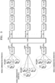
- FIG. 3 is a diagram illustrating a topology form of the DAS to which a method for summing downlink digital signal is applied according to an embodiment of the inventive concept.
- the method for summing downlink digital signal according to the embodiment of the inventive concept may be applied to a topology form of the DAS as shown in FIG. 3 , which includes a plurality of HEUs 100A, 100B, and 100C, a single HUB 200, and a plurality of RUs connected in a star structure or/and a cascade structure to the single HUB 200.
- the method for summing downlink digital signal may be applied to various types of signal distributed systems each including a plurality of upper nodes constituting an upper stage based on a signal transmission direction, and a middle node receiving a plurality of mobile communication signals from the plurality of upper nodes, the middle node distributing the mobile communication signals to a plurality of lower nodes branch-connected thereto.
- the embodiment of the inventive concept will be described in detail based on FIG. 3 .
- each of the HEUs 100A, 100B, and 100C receives mobile communication signals from a plurality of BTSs through transport mediums.
- each of the HEUs 100A, 100B, and 100C may perform digital signal conversion on the plurality of mobile communication signals from the plurality of BTSs and transmit the digital-converted mobile communication signals to the HUB 200.
- each of the HEUs 100A, 100B, and 100C receives mobile communication signals of different mobile communication operators.
- FIG. 3 it is assumed in FIG. 3 that one HEU and one mobile communication operator are matched one by one, the inventive concept is not limited thereto. That is, base stations covered by each HEU may not be base stations of different operators. In this case, the base station may be a base station unit concentrated on a remote place such as a BTS hotel.
- each HEU receives signals for each mobile communication service band from base station units of different operators will be mainly described.
- the HUB 200 may perform the downlink digital signal summing method according to the embodiment of the inventive concept.
- this will be described with reference to FIG. 4 .
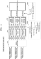
- FIG. 4 is a block diagram illustrating components for performing the method for summing downlink digital signal as a digital part of a hub unit according to the embodiment of the inventive concept.
- the digital part of the HUB 200 may include a signal input unit 210, a band extractor 220, a signal summer 230, and a reformatter 240.
- the signal input unit 210 allows mobile communication signals transmitted from each of the HEUs 100A, 100B, and 100C to be input to the band extractor 220.
- the signal input unit 210 may receive mobile communication signals input from each of the HEUs 100A, 100B, and 100C and then deframed.
- the signals input to the HUB for each mobile communication operator may include mobile communication signals in the WCDMA band, the LTE band, and the LTE-A band.
- the mobile communication signals for each mobile communication operator may be input, through the signal input unit 210, to a digital filter for each service band (see a digital filter for separating the WCDMA band, a digital filter for separating the LTE band, and a digital filter for separating the LTE-A band in FIG. 4 ).
- the band extractor 220 is provided with the digital filter for each service band, to separate only a signal corresponding to the service band.
- the mobile communication signals (A) of the mobile communication operator A, the mobile communication signals (B) of the mobile communication operator B, and the mobile communication signals (C) of the mobile communication operator C are band-separated by the digital filter for each service band.
- reference numeral (a1) designates a signal in the WCDMA band among the mobile communication signals (A) of the mobile communication operator A
- reference numeral (b1) designates a signal in the WCDMA band among the mobile communication signals (B) of the mobile communication operator B
- reference numeral (c1) designates a signal in the WCDMA band among the mobile communication signals (C) of the mobile communication operator C
- reference numeral (a2), (b2), or (c2) designate a signal in the LTE band among the mobile communication signals of each mobile communication operator
- reference numeral (a3), (b3), or (c3) designate a signal in the LTE-A band among the mobile communication signals of each mobile communication operator.
- the band extractor 220 is implemented with digital filters for each band is illustrated as an example. However, it will be apparent that various methods may be applied in addition to the band extraction method.
- the Sub-band 1 conceptually illustrates a frequency band used by the mobile communication operator A in a process of providing a specific mobile communication service
- the Sub-band 2 conceptually illustrates a frequency band used by the mobile communication operator B in a process of providing a specific mobile communication service
- the Sub-band 3 conceptually illustrates a frequency band used by the mobile communication operator C in a process of providing a specific mobile communication service.
- the sub-band signals extracted for each of the same mobile communication service bands through the band extractor 220 as described above are input to the signal summer 230.
- the signal summer 230 digitally sums the different sub-band signals in the same mobile communication service band, input through the band extractor 220. If the sub-band signals pass through the signal summer 230, the summing of the sub-band signal in the same mobile communication service band is performed as shown in reference numeral 230A of FIG. 4 , and a digital frame signal suitable for a transmission standard defined in the DAS is generated based on the summed signal through the reformatter 240.
- the digital frame signal passing through the reformatter 240 may be transmitted each RU branch-connected to the HUB 200 via a framer, an SERDES, and an E/O converter.
- digital downlink signal summing is performed on sub-band signals in the same service band, transmitted from a plurality of operators, in the DAS, thereby improving the efficiency of digital transmission.
Landscapes
- Engineering & Computer Science (AREA)
- Computer Networks & Wireless Communication (AREA)
- Signal Processing (AREA)
- Power Engineering (AREA)
- Mobile Radio Communication Systems (AREA)
Claims (9)
- Dispositif concentrateur (30, 200) pour un système d'antennes distribuées comprenant :un extracteur de bande (220) configuré pourrecevoir des signaux de communication mobile en liaison descendante provenant de différents opérateurs, dans lequel chacun des signaux de communication mobile en liaison descendante comprend une pluralité de signaux de sous-bande ayant des bandes de service différentes les unes des autres, etextrait les signaux de sous-bande correspondant à une même bande de service, par rapport à chacune des bandes de service, à partir des signaux de communication mobile en liaison descendante ; etun additionneur de signaux (230) configuré pour additionner numériquement les signaux de sous-bande extraits par rapport à chacune des bandes de service.
- Dispositif concentrateur selon la revendication 1, dans lequel les signaux de communication mobile en liaison descendante sont transmis à partir d'au moins une station de base (5) et une unité de noeud dans le système d'antennes distribuées.
- Dispositif concentrateur selon la revendication 2, dans lequel l'unité de noeud est une unité de tête (100A, 100B, 100C) ou une unité d'interface de station de base (10) dans le système d'antennes distribuées.
- Dispositif concentrateur selon la revendication 1, comprenant en outre :
un reformateur (240) configuré pour générer un signal de trame numérique adapté à une norme de transmission définie pour la transmission de signaux dans le système d'antennes distribuées sur la base des signaux additionnés numériquement. - Dispositif concentrateur selon la revendication 4, dans lequel le dispositif concentrateur est connecté de manière communicative à une pluralité d'unités distantes (40) configurées pour recevoir le signal de trame numérique et disposées à distance pour transmettre un signal radiofréquence (RF) à un terminal dans une zone de couverture de service sur la base du signal de trame numérique.
- Procédé de sommation de signaux par un dispositif concentrateur (30, 200) dans un système d'antennes distribuées, comprenant :la réception de signaux de communication mobile en liaison descendante provenant de différents opérateurs, chacun des signaux de communication mobile comprenant une pluralité de signaux de sous-bande ayant des bandes de service différentes les unes des autres;l'extraction des signaux de sous-bande correspondant à une même bande de service, par rapport à chacune des bandes de service, à partir des signaux de communication mobile en liaison descendante ; etla sommation numérique des signaux de sous-bande extraits par rapport à chacune des bandes de service.
- Procédé selon la revendication 6, comprenant en outre :
la génération d'un signal de trame numérique adapté à une norme de transmission définie pour la transmission de signaux dans le système d'antennes distribuées sur la base des signaux additionnés numériquement. - Dispositif d'addition de signaux inclus dans un système d'antennes distribuées, le dispositif d'addition de signaux comprenant :une mémoire ; etun processeur, couplé à la mémoire, pour faciliter l'exécution d'instructions stockées dans la mémoire ou d'instructions reçues d'un dispositif externe afin d'effectuer des opérations, comprenant :la réception de signaux de communication mobile en liaison descendante, chacun des signaux de communication mobile en liaison descendante comprenant une pluralité de signaux de sous-bande ayant des bandes de service différentes les unes des autres ;l'extraction des signaux de sous-bande correspondant à une même bande de service, par rapport à chacune des bandes de service, à partir des signaux de communication mobile en liaison descendante ; etla sommation numérique des signaux de sous-bande extraits par rapport à chacune des bandes de service.
- Dispositif de sommation de signaux selon la revendication 8, dans lequel les opérations comprennent en outre :
la génération d'un signal de trame numérique adapté à une norme de transmission définie pour la transmission de signaux dans le système d'antennes distribuées sur la base des signaux additionnés numériquement.
Applications Claiming Priority (3)
| Application Number | Priority Date | Filing Date | Title |
|---|---|---|---|
| KR20140194370 | 2014-12-30 | ||
| EP15875694.0A EP3242450B1 (fr) | 2014-12-30 | 2015-12-29 | Procédé de sommation de signal numérique vers l'avant dans un système d'antenne distribué |
| PCT/KR2015/014449 WO2016108600A1 (fr) | 2014-12-30 | 2015-12-29 | Procédé de sommation de signal numérique vers l'avant dans un système d'antenne distribué |
Related Parent Applications (1)
| Application Number | Title | Priority Date | Filing Date |
|---|---|---|---|
| EP15875694.0A Division EP3242450B1 (fr) | 2014-12-30 | 2015-12-29 | Procédé de sommation de signal numérique vers l'avant dans un système d'antenne distribué |
Publications (2)
| Publication Number | Publication Date |
|---|---|
| EP3627785A1 EP3627785A1 (fr) | 2020-03-25 |
| EP3627785B1 true EP3627785B1 (fr) | 2025-06-04 |
Family
ID=56284653
Family Applications (2)
| Application Number | Title | Priority Date | Filing Date |
|---|---|---|---|
| EP19208598.3A Active EP3627785B1 (fr) | 2014-12-30 | 2015-12-29 | Procédé de sommation de signal numérique vers l'avant dans un système d'antenne distribué |
| EP15875694.0A Active EP3242450B1 (fr) | 2014-12-30 | 2015-12-29 | Procédé de sommation de signal numérique vers l'avant dans un système d'antenne distribué |
Family Applications After (1)
| Application Number | Title | Priority Date | Filing Date |
|---|---|---|---|
| EP15875694.0A Active EP3242450B1 (fr) | 2014-12-30 | 2015-12-29 | Procédé de sommation de signal numérique vers l'avant dans un système d'antenne distribué |
Country Status (4)
| Country | Link |
|---|---|
| US (2) | US10111107B2 (fr) |
| EP (2) | EP3627785B1 (fr) |
| KR (1) | KR102226249B1 (fr) |
| WO (1) | WO2016108600A1 (fr) |
Families Citing this family (3)
| Publication number | Priority date | Publication date | Assignee | Title |
|---|---|---|---|---|
| JP6729059B2 (ja) * | 2016-06-24 | 2020-07-22 | 日本電気株式会社 | 中継装置、中継システム及び中継方法 |
| KR20190118824A (ko) | 2018-04-11 | 2019-10-21 | (주) 기산텔레콤 | 광 분산 중계 시스템에서의 역방향 링크 품질 개선 장치 및 방법 |
| KR102148706B1 (ko) | 2018-08-30 | 2020-08-27 | 주식회사 쏠리드 | 분산 안테나 시스템의 이중화 |
Family Cites Families (19)
| Publication number | Priority date | Publication date | Assignee | Title |
|---|---|---|---|---|
| US8737454B2 (en) * | 2007-01-25 | 2014-05-27 | Adc Telecommunications, Inc. | Modular wireless communications platform |
| US8310963B2 (en) * | 2008-06-24 | 2012-11-13 | Adc Telecommunications, Inc. | System and method for synchronized time-division duplex signal switching |
| US8208414B2 (en) * | 2008-06-24 | 2012-06-26 | Lgc Wireless, Inc. | System and method for configurable time-division duplex interface |
| US8346091B2 (en) * | 2009-04-29 | 2013-01-01 | Andrew Llc | Distributed antenna system for wireless network systems |
| ITMO20090135A1 (it) * | 2009-05-19 | 2010-11-20 | Teko Telecom S P A | Sistema e metodo per la distribuzione di segnali a radiofrequenza |
| US8588614B2 (en) * | 2009-05-22 | 2013-11-19 | Extenet Systems, Inc. | Flexible distributed antenna system |
| EP2580936B1 (fr) * | 2010-06-09 | 2018-11-28 | CommScope Technologies LLC | Minimisation de bruit sur la liaison montante |
| WO2012148940A1 (fr) * | 2011-04-29 | 2012-11-01 | Corning Cable Systems Llc | Systèmes, procédés et dispositifs pour augmenter la puissance radiofréquence (rf) dans systèmes d'antennes distribuées |
| WO2012168926A2 (fr) * | 2011-06-10 | 2012-12-13 | Technion R&D Foundation | Récepteur, émetteur et procédé pour le traitement numérique de plusieurs sous-bandes |
| KR102063140B1 (ko) * | 2011-10-27 | 2020-02-11 | 인텔 코포레이션 | 블록 기반 파고율 저감 |
| US9176769B2 (en) * | 2012-06-29 | 2015-11-03 | Microsoft Technology Licensing, Llc | Partitioned array objects in a distributed runtime |
| WO2014011832A1 (fr) * | 2012-07-11 | 2014-01-16 | Adc Telecommunications, Inc. | Système d'antenne distribué présentant une connectivité gérée |
| US9306682B2 (en) * | 2012-07-20 | 2016-04-05 | Commscope Technologies Llc | Systems and methods for a self-optimizing distributed antenna system |
| EP2789107B1 (fr) * | 2012-08-09 | 2017-02-15 | Axell Wireless Ltd. | Système d'antenne distribué centré sur capacité numérique |
| US9306669B2 (en) * | 2012-08-28 | 2016-04-05 | Advanced Rf Technologies, Inc. | Optic distributed antenna system supporting multi-band multi-carrier service over a reduced number of optic core lines |
| EP3285446B1 (fr) * | 2012-10-31 | 2020-10-14 | CommScope Technologies LLC | Transport de bande de base numérique dans des systèmes de distribution de télécommunications |
| US9179501B2 (en) * | 2013-02-20 | 2015-11-03 | Advanced Rf Technologies, Inc. | Multi-carrier integration apparatus for distributed antenna system |
| US20140320340A1 (en) * | 2013-02-21 | 2014-10-30 | Dali Systems Co. Ltd. | Indoor localization using analog off-air access units |
| WO2015116451A1 (fr) * | 2014-01-30 | 2015-08-06 | Commscope Technologies Llc | Optimisation de l'allocation de puissance dans des systèmes de distribution de signal utilisant des gains variables et statiques |
-
2015
- 2015-12-29 EP EP19208598.3A patent/EP3627785B1/fr active Active
- 2015-12-29 WO PCT/KR2015/014449 patent/WO2016108600A1/fr not_active Ceased
- 2015-12-29 EP EP15875694.0A patent/EP3242450B1/fr active Active
- 2015-12-29 KR KR1020177019909A patent/KR102226249B1/ko active Active
-
2016
- 2016-03-30 US US15/084,843 patent/US10111107B2/en active Active
-
2018
- 2018-09-14 US US16/131,312 patent/US10716011B2/en active Active
Also Published As
| Publication number | Publication date |
|---|---|
| US10716011B2 (en) | 2020-07-14 |
| US20160212630A1 (en) | 2016-07-21 |
| EP3627785A1 (fr) | 2020-03-25 |
| EP3242450A4 (fr) | 2018-09-19 |
| WO2016108600A1 (fr) | 2016-07-07 |
| US10111107B2 (en) | 2018-10-23 |
| KR20170091746A (ko) | 2017-08-09 |
| US20190014484A1 (en) | 2019-01-10 |
| EP3242450B1 (fr) | 2019-11-13 |
| EP3242450A1 (fr) | 2017-11-08 |
| KR102226249B1 (ko) | 2021-03-10 |
Similar Documents
| Publication | Publication Date | Title |
|---|---|---|
| US10383171B2 (en) | Digital data transmission in distributed antenna system | |
| KR102128800B1 (ko) | 분산 안테나 시스템 | |
| US10820215B2 (en) | Node unit of distributed antenna system | |
| KR102116539B1 (ko) | 원격 무선 장비 | |
| KR102189745B1 (ko) | 광 중계 시스템의 리모트 장치 | |
| US10716011B2 (en) | Downlink digital signal summation in distributed antenna system | |
| US20170117977A1 (en) | Node unit capable of measuring delay and distributed antenna system including the same | |
| KR20160126610A (ko) | 분산 안테나 시스템 및 이의 리모트 장치 | |
| US9572178B1 (en) | Node unit of distributed antenna system | |
| US20180198493A1 (en) | Distributed antenna system including crest factor reduction module disposed at optimum position | |
| US10693527B2 (en) | Distributed antenna system including crest factor reduction module disposed at optimum position | |
| KR102287210B1 (ko) | 분산 안테나 시스템의 노드 유닛 | |
| US10193599B2 (en) | Node unit of distributed antenna system | |
| KR102129051B1 (ko) | 교체 가능한 통신모듈을 포함하는 이동통신 중계기 | |
| KR102189727B1 (ko) | 분산 안테나 시스템에서의 cfr 배치 방법 | |
| KR20160082095A (ko) | 이동통신신호 및 서비스 주파수 대역 검출 장치 | |
| KR102262534B1 (ko) | 분산 안테나 시스템에서의 cfr 배치 방법 | |
| KR102246941B1 (ko) | 분산 안테나 시스템에서의 cfr 배치 방법 | |
| KR102189724B1 (ko) | 분산 안테나 시스템에서의 cfr 배치 방법 | |
| US10448323B2 (en) | Node unit of distributed antenna system | |
| KR101877269B1 (ko) | 이동통신신호의 대역 별 이득 조절 장치 |
Legal Events
| Date | Code | Title | Description |
|---|---|---|---|
| PUAI | Public reference made under article 153(3) epc to a published international application that has entered the european phase |
Free format text: ORIGINAL CODE: 0009012 |
|
| STAA | Information on the status of an ep patent application or granted ep patent |
Free format text: STATUS: REQUEST FOR EXAMINATION WAS MADE |
|
| 17P | Request for examination filed |
Effective date: 20191112 |
|
| AC | Divisional application: reference to earlier application |
Ref document number: 3242450 Country of ref document: EP Kind code of ref document: P |
|
| AK | Designated contracting states |
Kind code of ref document: A1 Designated state(s): AL AT BE BG CH CY CZ DE DK EE ES FI FR GB GR HR HU IE IS IT LI LT LU LV MC MK MT NL NO PL PT RO RS SE SI SK SM TR |
|
| STAA | Information on the status of an ep patent application or granted ep patent |
Free format text: STATUS: EXAMINATION IS IN PROGRESS |
|
| 17Q | First examination report despatched |
Effective date: 20211014 |
|
| GRAP | Despatch of communication of intention to grant a patent |
Free format text: ORIGINAL CODE: EPIDOSNIGR1 |
|
| STAA | Information on the status of an ep patent application or granted ep patent |
Free format text: STATUS: GRANT OF PATENT IS INTENDED |
|
| RIN1 | Information on inventor provided before grant (corrected) |
Inventor name: KIM, DO YOON Inventor name: KIM, HYOUNG HO |
|
| INTG | Intention to grant announced |
Effective date: 20250103 |
|
| GRAS | Grant fee paid |
Free format text: ORIGINAL CODE: EPIDOSNIGR3 |
|
| GRAA | (expected) grant |
Free format text: ORIGINAL CODE: 0009210 |
|
| STAA | Information on the status of an ep patent application or granted ep patent |
Free format text: STATUS: THE PATENT HAS BEEN GRANTED |
|
| AC | Divisional application: reference to earlier application |
Ref document number: 3242450 Country of ref document: EP Kind code of ref document: P |
|
| AK | Designated contracting states |
Kind code of ref document: B1 Designated state(s): AL AT BE BG CH CY CZ DE DK EE ES FI FR GB GR HR HU IE IS IT LI LT LU LV MC MK MT NL NO PL PT RO RS SE SI SK SM TR |
|
| REG | Reference to a national code |
Ref country code: GB Ref legal event code: FG4D |
|
| REG | Reference to a national code |
Ref country code: CH Ref legal event code: EP |
|
| REG | Reference to a national code |
Ref country code: DE Ref legal event code: R096 Ref document number: 602015091785 Country of ref document: DE |
|
| REG | Reference to a national code |
Ref country code: IE Ref legal event code: FG4D |
|
| REG | Reference to a national code |
Ref country code: NL Ref legal event code: MP Effective date: 20250604 |
|
| PG25 | Lapsed in a contracting state [announced via postgrant information from national office to epo] |
Ref country code: FI Free format text: LAPSE BECAUSE OF FAILURE TO SUBMIT A TRANSLATION OF THE DESCRIPTION OR TO PAY THE FEE WITHIN THE PRESCRIBED TIME-LIMIT Effective date: 20250604 Ref country code: ES Free format text: LAPSE BECAUSE OF FAILURE TO SUBMIT A TRANSLATION OF THE DESCRIPTION OR TO PAY THE FEE WITHIN THE PRESCRIBED TIME-LIMIT Effective date: 20250604 |
|
| REG | Reference to a national code |
Ref country code: LT Ref legal event code: MG9D |
|
| PG25 | Lapsed in a contracting state [announced via postgrant information from national office to epo] |
Ref country code: NO Free format text: LAPSE BECAUSE OF FAILURE TO SUBMIT A TRANSLATION OF THE DESCRIPTION OR TO PAY THE FEE WITHIN THE PRESCRIBED TIME-LIMIT Effective date: 20250904 Ref country code: GR Free format text: LAPSE BECAUSE OF FAILURE TO SUBMIT A TRANSLATION OF THE DESCRIPTION OR TO PAY THE FEE WITHIN THE PRESCRIBED TIME-LIMIT Effective date: 20250905 |
|
| PG25 | Lapsed in a contracting state [announced via postgrant information from national office to epo] |
Ref country code: PL Free format text: LAPSE BECAUSE OF FAILURE TO SUBMIT A TRANSLATION OF THE DESCRIPTION OR TO PAY THE FEE WITHIN THE PRESCRIBED TIME-LIMIT Effective date: 20250604 |
|
| PG25 | Lapsed in a contracting state [announced via postgrant information from national office to epo] |
Ref country code: BG Free format text: LAPSE BECAUSE OF FAILURE TO SUBMIT A TRANSLATION OF THE DESCRIPTION OR TO PAY THE FEE WITHIN THE PRESCRIBED TIME-LIMIT Effective date: 20250604 |
|
| PG25 | Lapsed in a contracting state [announced via postgrant information from national office to epo] |
Ref country code: HR Free format text: LAPSE BECAUSE OF FAILURE TO SUBMIT A TRANSLATION OF THE DESCRIPTION OR TO PAY THE FEE WITHIN THE PRESCRIBED TIME-LIMIT Effective date: 20250604 |
|
| PG25 | Lapsed in a contracting state [announced via postgrant information from national office to epo] |
Ref country code: RS Free format text: LAPSE BECAUSE OF FAILURE TO SUBMIT A TRANSLATION OF THE DESCRIPTION OR TO PAY THE FEE WITHIN THE PRESCRIBED TIME-LIMIT Effective date: 20250904 |
|
| PG25 | Lapsed in a contracting state [announced via postgrant information from national office to epo] |
Ref country code: LV Free format text: LAPSE BECAUSE OF FAILURE TO SUBMIT A TRANSLATION OF THE DESCRIPTION OR TO PAY THE FEE WITHIN THE PRESCRIBED TIME-LIMIT Effective date: 20250604 |
|
| PG25 | Lapsed in a contracting state [announced via postgrant information from national office to epo] |
Ref country code: NL Free format text: LAPSE BECAUSE OF FAILURE TO SUBMIT A TRANSLATION OF THE DESCRIPTION OR TO PAY THE FEE WITHIN THE PRESCRIBED TIME-LIMIT Effective date: 20250604 |
|
| PG25 | Lapsed in a contracting state [announced via postgrant information from national office to epo] |
Ref country code: PT Free format text: LAPSE BECAUSE OF FAILURE TO SUBMIT A TRANSLATION OF THE DESCRIPTION OR TO PAY THE FEE WITHIN THE PRESCRIBED TIME-LIMIT Effective date: 20251006 |
|
| REG | Reference to a national code |
Ref country code: AT Ref legal event code: MK05 Ref document number: 1801442 Country of ref document: AT Kind code of ref document: T Effective date: 20250604 |
|
| PG25 | Lapsed in a contracting state [announced via postgrant information from national office to epo] |
Ref country code: IS Free format text: LAPSE BECAUSE OF FAILURE TO SUBMIT A TRANSLATION OF THE DESCRIPTION OR TO PAY THE FEE WITHIN THE PRESCRIBED TIME-LIMIT Effective date: 20251004 |
|
| PGFP | Annual fee paid to national office [announced via postgrant information from national office to epo] |
Ref country code: GB Payment date: 20251218 Year of fee payment: 11 |
|
| PG25 | Lapsed in a contracting state [announced via postgrant information from national office to epo] |
Ref country code: AT Free format text: LAPSE BECAUSE OF FAILURE TO SUBMIT A TRANSLATION OF THE DESCRIPTION OR TO PAY THE FEE WITHIN THE PRESCRIBED TIME-LIMIT Effective date: 20250604 Ref country code: SM Free format text: LAPSE BECAUSE OF FAILURE TO SUBMIT A TRANSLATION OF THE DESCRIPTION OR TO PAY THE FEE WITHIN THE PRESCRIBED TIME-LIMIT Effective date: 20250604 |
|
| PGFP | Annual fee paid to national office [announced via postgrant information from national office to epo] |
Ref country code: FR Payment date: 20251218 Year of fee payment: 11 |
|
| PG25 | Lapsed in a contracting state [announced via postgrant information from national office to epo] |
Ref country code: CZ Free format text: LAPSE BECAUSE OF FAILURE TO SUBMIT A TRANSLATION OF THE DESCRIPTION OR TO PAY THE FEE WITHIN THE PRESCRIBED TIME-LIMIT Effective date: 20250604 |
|
| PG25 | Lapsed in a contracting state [announced via postgrant information from national office to epo] |
Ref country code: EE Free format text: LAPSE BECAUSE OF FAILURE TO SUBMIT A TRANSLATION OF THE DESCRIPTION OR TO PAY THE FEE WITHIN THE PRESCRIBED TIME-LIMIT Effective date: 20250604 |
|
| PG25 | Lapsed in a contracting state [announced via postgrant information from national office to epo] |
Ref country code: RO Free format text: LAPSE BECAUSE OF FAILURE TO SUBMIT A TRANSLATION OF THE DESCRIPTION OR TO PAY THE FEE WITHIN THE PRESCRIBED TIME-LIMIT Effective date: 20250604 Ref country code: SK Free format text: LAPSE BECAUSE OF FAILURE TO SUBMIT A TRANSLATION OF THE DESCRIPTION OR TO PAY THE FEE WITHIN THE PRESCRIBED TIME-LIMIT Effective date: 20250604 |
|
| REG | Reference to a national code |
Ref country code: DE Ref legal event code: R097 Ref document number: 602015091785 Country of ref document: DE |
|
| PLBE | No opposition filed within time limit |
Free format text: ORIGINAL CODE: 0009261 |
|
| STAA | Information on the status of an ep patent application or granted ep patent |
Free format text: STATUS: NO OPPOSITION FILED WITHIN TIME LIMIT |
|
| PG25 | Lapsed in a contracting state [announced via postgrant information from national office to epo] |
Ref country code: DK Free format text: LAPSE BECAUSE OF FAILURE TO SUBMIT A TRANSLATION OF THE DESCRIPTION OR TO PAY THE FEE WITHIN THE PRESCRIBED TIME-LIMIT Effective date: 20250604 |
|
| PGFP | Annual fee paid to national office [announced via postgrant information from national office to epo] |
Ref country code: DE Payment date: 20251222 Year of fee payment: 11 |
|
| PGFP | Annual fee paid to national office [announced via postgrant information from national office to epo] |
Ref country code: IT Payment date: 20251231 Year of fee payment: 11 |
|
| REG | Reference to a national code |
Ref country code: CH Ref legal event code: L10 Free format text: ST27 STATUS EVENT CODE: U-0-0-L10-L00 (AS PROVIDED BY THE NATIONAL OFFICE) Effective date: 20260416 |