EP3627805B1 - Terminal mobile pliable - Google Patents
Terminal mobile pliable Download PDFInfo
- Publication number
- EP3627805B1 EP3627805B1 EP18803145.4A EP18803145A EP3627805B1 EP 3627805 B1 EP3627805 B1 EP 3627805B1 EP 18803145 A EP18803145 A EP 18803145A EP 3627805 B1 EP3627805 B1 EP 3627805B1
- Authority
- EP
- European Patent Office
- Prior art keywords
- shell
- sliding plate
- mobile terminal
- support
- foldable
- Prior art date
- Legal status (The legal status is an assumption and is not a legal conclusion. Google has not performed a legal analysis and makes no representation as to the accuracy of the status listed.)
- Active
Links
Images







Classifications
-
- G—PHYSICS
- G06—COMPUTING OR CALCULATING; COUNTING
- G06F—ELECTRIC DIGITAL DATA PROCESSING
- G06F1/00—Details not covered by groups G06F3/00 - G06F13/00 and G06F21/00
- G06F1/16—Constructional details or arrangements
- G06F1/1613—Constructional details or arrangements for portable computers
- G06F1/1615—Constructional details or arrangements for portable computers with several enclosures having relative motions, each enclosure supporting at least one I/O or computing function
- G06F1/1616—Constructional details or arrangements for portable computers with several enclosures having relative motions, each enclosure supporting at least one I/O or computing function with folding flat displays, e.g. laptop computers or notebooks having a clamshell configuration, with body parts pivoting to an open position around an axis parallel to the plane they define in closed position
-
- G—PHYSICS
- G06—COMPUTING OR CALCULATING; COUNTING
- G06F—ELECTRIC DIGITAL DATA PROCESSING
- G06F1/00—Details not covered by groups G06F3/00 - G06F13/00 and G06F21/00
- G06F1/16—Constructional details or arrangements
- G06F1/1613—Constructional details or arrangements for portable computers
- G06F1/1633—Constructional details or arrangements of portable computers not specific to the type of enclosures covered by groups G06F1/1615 - G06F1/1626
- G06F1/1637—Details related to the display arrangement, including those related to the mounting of the display in the housing
- G06F1/1641—Details related to the display arrangement, including those related to the mounting of the display in the housing the display being formed by a plurality of foldable display components
-
- G—PHYSICS
- G06—COMPUTING OR CALCULATING; COUNTING
- G06F—ELECTRIC DIGITAL DATA PROCESSING
- G06F1/00—Details not covered by groups G06F3/00 - G06F13/00 and G06F21/00
- G06F1/16—Constructional details or arrangements
- G06F1/1613—Constructional details or arrangements for portable computers
- G06F1/1633—Constructional details or arrangements of portable computers not specific to the type of enclosures covered by groups G06F1/1615 - G06F1/1626
- G06F1/1637—Details related to the display arrangement, including those related to the mounting of the display in the housing
- G06F1/1652—Details related to the display arrangement, including those related to the mounting of the display in the housing the display being flexible, e.g. mimicking a sheet of paper, or rollable
-
- G—PHYSICS
- G06—COMPUTING OR CALCULATING; COUNTING
- G06F—ELECTRIC DIGITAL DATA PROCESSING
- G06F1/00—Details not covered by groups G06F3/00 - G06F13/00 and G06F21/00
- G06F1/16—Constructional details or arrangements
- G06F1/1613—Constructional details or arrangements for portable computers
- G06F1/1633—Constructional details or arrangements of portable computers not specific to the type of enclosures covered by groups G06F1/1615 - G06F1/1626
- G06F1/1656—Details related to functional adaptations of the enclosure, e.g. to provide protection against EMI, shock, water, or to host detachable peripherals like a mouse or removable expansions units like PCMCIA cards, or to provide access to internal components for maintenance or to removable storage supports like CDs or DVDs, or to mechanically mount accessories
- G06F1/166—Details related to functional adaptations of the enclosure, e.g. to provide protection against EMI, shock, water, or to host detachable peripherals like a mouse or removable expansions units like PCMCIA cards, or to provide access to internal components for maintenance or to removable storage supports like CDs or DVDs, or to mechanically mount accessories related to integrated arrangements for adjusting the position of the main body with respect to the supporting surface, e.g. legs for adjusting the tilt angle
-
- G—PHYSICS
- G06—COMPUTING OR CALCULATING; COUNTING
- G06F—ELECTRIC DIGITAL DATA PROCESSING
- G06F1/00—Details not covered by groups G06F3/00 - G06F13/00 and G06F21/00
- G06F1/16—Constructional details or arrangements
- G06F1/1613—Constructional details or arrangements for portable computers
- G06F1/1633—Constructional details or arrangements of portable computers not specific to the type of enclosures covered by groups G06F1/1615 - G06F1/1626
- G06F1/1675—Miscellaneous details related to the relative movement between the different enclosures or enclosure parts
- G06F1/1681—Details related solely to hinges
-
- G—PHYSICS
- G09—EDUCATION; CRYPTOGRAPHY; DISPLAY; ADVERTISING; SEALS
- G09F—DISPLAYING; ADVERTISING; SIGNS; LABELS OR NAME-PLATES; SEALS
- G09F9/00—Indicating arrangements for variable information in which the information is built-up on a support by selection or combination of individual elements
- G09F9/30—Indicating arrangements for variable information in which the information is built-up on a support by selection or combination of individual elements in which the desired character or characters are formed by combining individual elements
- G09F9/301—Indicating arrangements for variable information in which the information is built-up on a support by selection or combination of individual elements in which the desired character or characters are formed by combining individual elements flexible foldable or roll-able electronic displays, e.g. thin LCD, OLED
-
- H—ELECTRICITY
- H04—ELECTRIC COMMUNICATION TECHNIQUE
- H04M—TELEPHONIC COMMUNICATION
- H04M1/00—Substation equipment, e.g. for use by subscribers
- H04M1/02—Constructional features of telephone sets
- H04M1/0202—Portable telephone sets, e.g. cordless phones, mobile phones or bar type handsets
- H04M1/0206—Portable telephones comprising a plurality of mechanically joined movable body parts, e.g. hinged housings
- H04M1/0208—Portable telephones comprising a plurality of mechanically joined movable body parts, e.g. hinged housings characterized by the relative motions of the body parts
- H04M1/0214—Foldable telephones, i.e. with body parts pivoting to an open position around an axis parallel to the plane they define in closed position
- H04M1/0216—Foldable in one direction, i.e. using a one degree of freedom hinge
- H04M1/022—The hinge comprising two parallel pivoting axes
-
- H—ELECTRICITY
- H04—ELECTRIC COMMUNICATION TECHNIQUE
- H04M—TELEPHONIC COMMUNICATION
- H04M1/00—Substation equipment, e.g. for use by subscribers
- H04M1/02—Constructional features of telephone sets
- H04M1/0202—Portable telephone sets, e.g. cordless phones, mobile phones or bar type handsets
- H04M1/026—Details of the structure or mounting of specific components
- H04M1/0266—Details of the structure or mounting of specific components for a display module assembly
- H04M1/0268—Details of the structure or mounting of specific components for a display module assembly including a flexible display panel
Definitions
- the Chinese Patent Application No. 201620544672.3 discloses a hinge of mobile terminal having a flexible screen.
- An outer side of the hinge supports the flexible screen.
- the hinge includes a main support, a first and a second bracket rotatably connected to a rotational shaft of the hinge.
- the first and the second bracket are slidably connected to a first support, a second support, and a synchronous control mechanism.
- An auxiliary support is provided between the first support and the main support, and between the second support and the main support.
- the auxiliary support corresponds to a bent region of the hinge when the hinge is folded.
- the hinge further includes a first guiding structure and a second guiding structure.
- the first guiding structure and the first support rotate together around the hinge rotational shaft.
- the second guiding structure and the second support rotate together around the hinge rotational shaft.
- the second rotation assembly may include a second sliding plate, a second rotation shaft, and a second connection rod.
- the second sliding plate is capable of being at least partially received in the second shell and is able to slide towards or away from the second shell.
- the second rotation shaft is arranged on the second sliding plate.
- a first end of the second connection rod is slidable on the second rotation shaft and rotatable relative to the second rotation shaft, and a second end of the second connection rod is capable of being rotatably connected to the second shell.
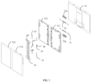
- the flexible display screen 10 may be arranged at an outside of the mobile terminal 10.
- an extending length of a side of the shell assembly 30 facing towards the flexible display screen 10 (the length along a direction parallel to an X-axis shown in FIG. 1 ) may be equal to an extending length of a side of the shell assembly 30 facing away from the flexible display screen 10 (the length along the direction parallel to the X-axis shown in FIG. 1 ).
- the shell assembly 30 itself may have a thickness (the thickness is along a direction parallel to an Y-axis shown in FIG.
- the first shell 31 may include a first front shell 311 and a first back shell 312 connected to each other.
- the second shell 32 may include a second front shell 321 and a second back shell 322 connected to each other.
- the connection may be achieved by screwing, adhesion, welding, and the like.
- the flexible display screen 10 may be disposed on the first front shell 311 and the second front shell 321.
- the flexible display screen 10 may have a display region, and the display region may be rectangular or rounded rectangular in the unfolded state.
- a space may be formed between the first front shell 311 and the first back shell 312 along the direction parallel to the Y-axis.
- a space may be formed between the second front shell 321 and the second back shell 322 along the direction parallel to the Y-axis.
- Another space may be formed between the first shell 31 and the second shell 32 along the direction parallel to the X-axis.
- the foldable mechanism may be arranged within the space between the first shell 31 and the second shell 32 along the direction parallel to the X-axis, and at least a partial structure of the foldable mechanism 20 may be received in the first shell 31 and the second shell 32.
- the space between the first shell 31 and the second shell 32 along the direction parallel to the X-axis may be changed during the rotation of the first shell 31 and the second shell around the foldable mechanism 20. Therefore, during the rotation of the first shell 31 and the second shell 32 around the foldable mechanism 20, the foldable mechanism 20 may be retracted into the first shell 31 and the second shell 32 at varying levels. As shown in FIG. 4 and FIG.
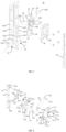
- the foldable mechanism 20 may include a first rotation assembly 50 and a second rotation assembly 60.
- the first rotation assembly 50 may be connected to the first shell 31.
- the rotation assembly 50 may be at least partially received inside the first shell 31, and may slidably extend and retract with respect to (i.e., slide away from or towards) the first shell 31.
- the second rotation assembly 60 may be connected to the second shell 32.
- the second rotation assembly 60 may be at least partially received inside second shell 32, and may slidably extend and retract with respect to (slide away from or towards) the second shell 32.
- the first rotation assembly 50 and the second rotation assembly 60 may have a same structure.
- the first rotation assembly 50 and the second rotation assembly 60 may be symmetrically distributed about a central axis I-I (shown in FIG. 5 ) between the first rotation assembly 50 and the second rotation assembly 60.
- I-I shown in FIG. 5
- the first shell 31 and the second shell 32 may be folded and unfolded symmetrically about the central axis I-I.
- the first rotation assembly 50 may include a first sliding plate 51, a first rotation shaft 53, and a first connection rod 54.
- the first rotation shaft 53 may be arranged on the first sliding plate 51.
- a first end 541 of the first connection rod 54 may be slidably hinged to the first rotation shaft 53, and a second end 542 of the first connection rod 54 may be rotatably connected to the first shell 31.
- the first sliding plate 51 may be at least partially received in the first shell 31, and slidably extend and retract with respect to (i.e., slide away from or towards) the first shell 31.
- two first rotation shafts 53 and two first connection rods 54 may be arranged on the first sliding plate 51.
- the two first rotation shafts 53 may be arranged symmetrically about a middle position of the first sliding plate 51 along a direction parallel to a Z-axis
- the two first connection rods 54 may be arranged symmetrically about a middle position of the first sliding plate 51 along the direction parallel to the Z-axis.
- the number of the first rotation shaft 53 may be one or more
- the number of the first connection rod 54 may be one or more. Slidable extension and retraction of the first sliding plate 51 with respect to the first shell 31 may be achieved with various numbers of the first rotation shafts 53 and the first connection rods 54.
- two second rotation shafts 63 and two second connection rods 64 may be arranged on the second sliding plate 61.
- the two second rotation shafts 63 may be arranged symmetrically about a middle position of the second sliding plate 61 along the direction parallel to the Z-axis
- the two second connection rods 64 may be arranged symmetrically about a middle position of the second sliding plate 61 along the direction parallel to the Z-axis.
- the number of the second rotation shafts 63 may be one or more
- the number of the second connection rods 64 may be one or more. Slidable extension and retraction of the second sliding plate 61 with respect to the second shell 32 may be achieved with various numbers of the second rotation shafts 63 and the second connection rods 64.
- the foldable mechanism 20 may include a linkage element 22 connected to the first rotation shaft 53 and the second rotation shaft 63.
- the linkage element 22 may have a first through hole 221 and a second through hole 222. The first through hole 221 and the second through hole 222 may be spaced apart from each other.
- the first rotation shaft 53 may be arranged to extend through the first through hole 221, and the second rotation shaft 63 may be arranged to extend through the second through hole 222.
- the linkage element 22 may link the first end 541 of the first connection rod 54 and the first end 641 of the second connection rod 64 to move at the same time. That is, by virtue of the linkage element 22, sliding of the first end 541 of the first connection rod 54 along the first rotation shaft 53 may lead to sliding of the first end 641 of the second connection rod 64 along the second rotation shaft 63, and vice versa.
- the linkage element 22 may allow the first connection rod 54 which is slidably hinged to the first rotation shaft 53 and the second connection rod 64 which is slidably hinged to the second rotation shaft 63 to move synchronously. That is, the slidable extension and retraction of the first sliding plate 51 with respect to the first shell 31 is synchronous with the slidable extension and retraction of the second sliding plate 61 with respect to the second shell 32, such that a symmetric folding and unfolding of the first shell 31 and the second shell 32 may be further achieved.
- the linkage element 22 may be made of metals or plastics.
- the first sliding member 52 may include two sleeve tubes 521 and a connection arm 522 connected between the two sleeve tubes 521.
- the first rotation shaft 53 may extend through the sleeve tubes 521 of the first sliding member 52.
- the first sliding member 52 may slide along the first rotation shaft 53 and rotate with respect to the first rotation shaft 53.
- the first end 541 of the first connection rod 54 may be rotatably connected to the connection arm 522 of the first sliding member 52. Further, the connection arm 522 of the first sliding member 52 may have a first positioning hole 523, and the first end 541 of the first connection rod 54 may have a first positioning protrusion 543. The first positioning protrusion 543 may be inserted into the first positioning hole 523.
- the second rotation assembly 60 may further include a second sliding member 62.
- the slidable hinge between the second connection rod 64 and the second rotation shaft 63 may be achieved by the second sliding member 62.
- the second sliding member 62 may be arranged to sleeve on the second rotation shaft 63 in a slidable manner, and the first end 641 of the second connection rod 64 may be rotatably connected to the second sliding member 62.
- the linkage element 22 may include a first arm portion 223 having the first through hole 221 and a second arm portion 224 having the second through hole 222.
- the first arm portion 223 may be arranged between the two sleeve tubes 521 of the first sliding member 52.
- the second arm portion 224 may be arranged between the two sleeve tubes 621 of the second sliding member 62.
- the first rotation shaft 53 may extend through the first through hole 221, and the second rotation shaft 63 may extend through the second through hole 222.
- the linkage element 22 may serve as a link between the first sliding member 52 and the second sliding member 62, such that the sliding of the first sliding member 52 along the first rotation shaft 53 may be synchronous with the sliding of the second sliding member 62 along the second rotation shaft 63.
- the first rotation assembly 50 may further include a first support 56, and the first rotation shaft 53 may be configured on the first sliding plate 51 through the first support 56. Further, the first support 56 may be fixed on the first sliding plate 51 by screw fastening. The first rotation shaft 53 may extend through the first support 56, and the second sliding member 52 may be arranged between the first support 56 and the first sliding plate 51.
- first support 56 By arranging the first support 56, relative movement of the first sliding member 52, the first end 541 of the first connection rod 54, and the first rotation shaft 53 may be restricted within a space between the first support 56 and the first sliding plate 51, such that the first end 541 of the first connection rod 54 may be prevented from detaching from the first sliding member 52.
- the second rotation assembly 60 may further include a second support 66, and the second rotation shaft 63 may be configured on the second sliding plate 61 through the second support 66. Further, the second support 66 may be fixed on the second sliding plate 61 by screw fastening. The second rotation shaft 63 may extend through the second support 66, and the second sliding member 62 may be arranged between the second support 66 and the second sliding plate 61.
- the two first engaging portions 571 of the first spring clamp 57 may respectively correspond to two ends of a sliding path of the first end 541 of the first connection rod 54 while the first end 541 slides along the first rotation shaft 53. To some extent, interference may be generated between each first engaging portion 571 and the first end 541 of the first connection rod 54, such that the first engaging portion 571 may apply a clamping force to the first end 541 of the first connection rod 54, and the position of the first connection rod 54 may not be changed randomly. Therefore, the first sliding plate 51 may be arranged at a stable position with respect to the first shell 31, that is, the foldable mobile terminal may stably remain in the folded or unfolded state.
- the first spring clamp 57 may further include a first damping portion 572 disposed between the two first engaging portions 571.
- a resistance may be increased. Increasing of the resistance may be achieved as a clamping force applied to the first positioning protrusion 543 by the first damping portion 572 is greater than the clamping force applied to the first positioning protrusion 543 by the first engaging portion 571.
- the first spring clamp 57 may be stadium-shaped with an opening at an end and closed at an opposing end.
- the two first engaging portions 571 may be arranged at the two opposite ends of the first spring clamp 57, and the first damping portion 572 may be arranged at a middle portion of the first spring clamp 57.
- a first gap 572a formed in the first damping portion 572 for the first positioning protrusion 543 to extend through may be smaller than a second gap 571a formed in the first engaging portion 571 for the first positioning protrusion 543 to extend through. Therefore, during the sliding from the first engaging portion 571 to the first damping portion 572, the first connection rod 54 may receive an increased resistance.
- the first receiving cavity 560 may include two first positioning cavities 561 and a first releasing cavity 562. Each of the two first positioning cavities 561 may correspond to each of the first engaging portion 571 of the first spring clamp 57.
- the first releasing cavity 562 may be formed between the two first positioning cavities 561. A size of the first releasing cavity 562 may be greater than a size of each first positioning cavity 561.
- the first engaging portion 571 may be fixed to be unmovable.
- the first damping portion 572 arranged between the two first engaging portions 571 may be correspondingly arranged in the first releasing cavity 562.
- the first releasing cavity 562 may offer a space allowing the first damping portion 572 to be elastically deformed.
- the second rotation assembly 60 may further include a second spring clamp 67 arranged on the second sliding plate 61.
- the first end 641 of the second connection rod 64 may reach two extreme positions along a direction of sliding, and the second spring clamp 67 may include two second engaging portions 671. Each of the two second engaging portions 671 may correspond to each of the two extreme positions.
- the second spring clamp 67 may be fixed on the second sliding plate 61 through the second support 66, and the second spring clamp 67 may be disposed inside the second support 66.
- the second positioning protrusion 643 at the first end 641 of the second connection rod 64 may extend through two opposing sides of the first end 641. An end of the second positioning protrusion 643 may be engaged in the second positioning hole 623 of the second sliding member 62, and an opposing end of the second positioning protrusion 643 may be inserted into the second engaging portion 671 of the second spring clamp 67. The second engaging portion 671 may clamp the second positioning protrusion 643 to apply a certain clamping force to the second connection rod 64.
- the two second engaging portions 671 may be arranged at two ends of the second spring clamp 67, and the second damping portion 672 may be arranged at a middle portion of the second spring clamp 67.
- a third gap 672a formed in the second damping portion 672 for the second positioning protrusion 643 to extend through may be smaller than a fourth gap 671a formed in the second engaging portion 671 for the second positioning protrusion 643 to extend through. Therefore, during the sliding from the second engaging portion 671 to the second damping portion 672, the second connection rod 64 may receive an increased resistance.
- the second support 66 may have a second receiving cavity 660, and the second spring clamp 67 may be received in the second receiving cavity 660.
- the second sliding plate 61 may close the second receiving cavity 660, such that the second spring clamp 67 may be fixed inside the second receiving cavity 660.
- the second receiving cavity 660 may include two second positioning cavities 661 and a second releasing cavity 662.
- Each of the two second positioning cavities 661 may correspond to each second engaging portion 671 of the second spring clamp 67.
- the second releasing cavity 662 may be formed between the two second positioning cavities 661.
- a size of the second releasing cavity 662 may be greater than a size of each second positioning cavity 661.
- the second damping portion 672 arranged between the two second engaging portions 671 may be arranged in the second releasing cavity 662.
- the second releasing cavity 662 may offer a space allowing the second damping portion 672 to be elastically deformed.
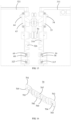
- an outer end of the first elongated hole 703 and an outer end of the second elongated hole 704 of the joining sheet 70 may abut against the corresponding pressing element 71.
- the first shell 31 and the second shell 32 may be prevented from departing from each other continually, and the first shell 31 and the second shell 32 may be protected from being overly stretched.
- the joining sheet 70 may slide with respect to the first shell 31 and the second shell 32 to adapt to the length change of the first and the second shells 31 and 32.
- a surface of each of the first decoration component 72a and the second decoration component 72b facing towards the flexible display screen 10 may be substantially flat to allow an easy configuration of the flexible display screen 10.
- a connective structure such as a protruding block 721
- a plurality of ridges 722 may be further arranged on the surface of each of the first decoration component 72a and the second decoration component 72b facing away from the flexible display screen 10.
- the first shell 31 may have two or more first notches 316 spaced apart from each other.
- each of the two or more first notches 316 may be formed at a side of the first front shell 311 close to the first rotation assembly 50.
- Two or more first latches 511 may be configured on the first sliding plate 51 and correspond to the two or more first notches 316.
- the first sliding plate 51 may include a first substrate 510, and the first latch 511 may be arranged on the first substrate 510.
- the first substrate 510 may be disposed between the first front shell 311 and the first back shell 312 and may slidably extend and retract between the first front shell 311 and the first back shell 312 (that is, slide away from or towards the first front shell 311).
- the first latch 511 and the first front shell 311 may be in a same plane.
- the plane may be parallel to a plane defined by the XZ-axes.
- the first latch 511 and the first front shell 311 may be configured to cooperatively support the flexible display screen 10.
- the second shell 32 may have two or more second notches 326 spaced apart from each other.
- each of the two or more second notches 326 may be formed at a side of the second front shell 321 close to the second rotation assembly 60.
- Two or more second latches 611 may be configured on the second sliding plate 61 and correspond to the two or more second notches 326.
- an end of each of the first latches 511 away from the first shell 31 may be connected to each other to form a first supportive beam 513.
- an end of each of the second latches 611 away from the second shell 32 may be connected to each other to form a second supportive beam 613.
- At least a partial structure of the supportive strip 26 may be disposed on the first supportive beam 513 and the second supportive beam 613.
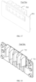
- the first roller 58 and the first spring 59 may be disposed between the first sliding plate 51 and the first back shell 312. In some other embodiments, the first roller 58 and the first spring 59 may be disposed between the first sliding plate 51 and the first front shell 311. According to some embodiments shown in FIG. 4 and FIG. 13 , the first groove 514 may be formed in a side wall of the first latch 511 of the first sliding plate 51 and face towards an adjacent first latch 511 arranged on the first substrate 510.
- At least two sets of the first rollers 58 and the first springs 59 may be provided.
- Each of two opposing side walls of the first latch 511 may have the first groove 514 matching with the first roller 58.
- two opposing side walls of the first notch 316 may be recessed away from the corresponding first latch 511 to form two first cavities 317.
- Each of the two first cavities 317 may be formed to receive one set of the first roller 58 and the first spring 59.
- the side wall of the first latch 511 may have two first grooves 514 at two terminating positions corresponding to the first sliding plate 51.
- one of the terminating positions may be located at an end of the first latch 511 close to the first shell 31, and the other one of the terminating positions may be located at an intersection between the first latch 511 and the first supportive beam 513.
- the first roller 58 may respectively enter the first groove 514 of the corresponding one of the two terminating positions. Therefore, the user of the foldable mobile terminal may feel a standstill if the foldable mobile terminal is folded or unfolded to an appropriate position.
- a side wall in the second notch 326 may be recessed inwardly away from a corresponding second latch 611 to form a second cavity 327.
- the second roller 68 and the second spring 69 may be received in the second cavity 327.
- the second spring 69 may abut against the second roller 68 to allow at least a part of the second roller 68 to be exposed to an outside of the second cavity 327, such that the second roller 68 may elastically abut against a side wall of the corresponding second latch 611.
Landscapes
- Engineering & Computer Science (AREA)
- Computer Hardware Design (AREA)
- Theoretical Computer Science (AREA)
- Physics & Mathematics (AREA)
- General Engineering & Computer Science (AREA)
- General Physics & Mathematics (AREA)
- Human Computer Interaction (AREA)
- Signal Processing (AREA)
- Mathematical Physics (AREA)
- Telephone Set Structure (AREA)
Claims (15)
- Mécanisme pliable (20) pour un terminal mobile pliable, ce terminal mobile pliable comportant une première coque (31) et une deuxième coque (32) reliées l'une à l'autre, ce mécanisme pliable (20) comprenant :
un premier ensemble de rotation (50), capable d'être relié à la première coque (31) et comportant :une première plaque coulissante (51), capable d'être reçue au moins partiellement dans la première coque (31) et capable de coulisser vers ou à l'écart de la première coque (31) ;un premier axe de rotation (53), disposé sur la première plaque coulissante (51) ; etune première tige de liaison (54), une première extrémité (541) de cette première tige de liaison (54) pouvant coulisser sur le premier axe de rotation (53) et pouvant tourner par rapport au premier axe de rotation (53), et une deuxième extrémité (542) de cette première tige de liaison (54) étant capable d'être reliée de manière rotative à la première coque (31) ; etun deuxième ensemble de rotation (60), capable d'être relié à la deuxième coque (32) et comportant :une deuxième plaque coulissante (61), capable d'être reçue au moins partiellement dans la deuxième coque (32) et capable de coulisser vers ou à l'écart de la deuxième coque (32) ; etun deuxième axe de rotation (63), disposé sur la deuxième plaque coulissante (61) ; etune deuxième tige de liaison (64), une première extrémité (641) de cette deuxième tige de liaison (64) pouvant coulisser sur le deuxième axe de rotation (63) et pouvant tourner par rapport au deuxième axe de rotation (63), et une deuxième extrémité (642) de cette deuxième tige de liaison (64) étant capable d'être reliée de manière rotative à la deuxième coque (32) ;le mécanisme pliable (20) étant caractérisé en ce que :le premier ensemble de rotation (50) comporte en outre un premier support (56), et le premier axe de rotation (53) est configuré sur la première plaque coulissante (51) au moyen de ce premier support (56) ; et en ce que le deuxième ensemble de rotation (60) comporte en outre un deuxième support (66), et le deuxième axe de rotation (63) est configuré sur la deuxième plaque coulissante (61) au moyen de ce deuxième support (66) ; et en ce que le mécanisme pliable (20) comprend en outre une bande de support (26), cette bande de support (26) étant reçue au moins partiellement dans un espace entre le premier support (56) et le deuxième support (66), cette bande de support (26), le premier support (56) et le deuxième support (66) étant configurés coopérativement de façon à supporter l'écran d'affichage flexible (10) ; et en ce quela bande de support (26) a une face incurvée. - Mécanisme pliable pour le terminal mobile pliable selon la revendication 1, ce mécanisme pliable (20) comprenant en outre un élément de liaison (22) relié au premier axe de rotation (53) et au deuxième axe de rotation (63) ;
cet élément de liaison (22) ayant un premier trou débouchant (221) et un deuxième trou débouchant (222) ; le premier axe de rotation (53) étant disposé de façon à s'étendre à travers le premier trou débouchant (221), et le deuxième axe de rotation (63) étant disposé de façon à s'étendre à travers le deuxième trou débouchant (222). - Mécanisme pliable (20) pour le terminal mobile pliable selon la revendication 1 ou 2, comprenant en outre un premier galet (58) et un premier ressort (59), la première plaque coulissante (51) ayant une première rainure (514) ; le premier ressort (59) et le premier galet (58) étant capables de buter à la fois contre la première coque (31) et contre la première plaque coulissante (51) ; lorsque la première plaque coulissante (51) coulisse vers ou à l'écart de la première coque (31), le premier galet (58) est capable d'entrer dans ou de sortir de la première rainure (514).
- Mécanisme pliable (20) pour le terminal mobile pliable selon l'une quelconque des revendications 1 à 3, comprenant en outre un deuxième galet (68) et un deuxième ressort (69), la deuxième plaque coulissante (61) ayant une deuxième rainure (614) ; le deuxième ressort (69) et le deuxième galet (68) étant capables de buter à la fois contre la deuxième coque (32) et contre la deuxième plaque coulissante (61) ; lorsque la deuxième plaque coulissante (61) coulisse vers ou à l'écart de la deuxième coque (32), le deuxième galet (68) est capable d'entrer dans ou de sortir de la deuxième rainure (614).
- Mécanisme pliable (20) pour le terminal mobile pliable selon l'une quelconque des revendications 1 à 4, dans lequel le premier ensemble de rotation (50) comporte en outre un premier élément coulissant (52), ce premier élément coulissant (52) coulissant sur le premier axe de rotation (53), et la première extrémité (541) de la première tige de liaison (54) étant reliée de manière rotative au premier élément coulissant (52) ; et dans lequel
le deuxième ensemble de rotation (60) comporte3 en outre un deuxième élément coulissant (62), ce deuxième élément coulissant (62) coulissant sur le deuxième axe de rotation (63), et la première extrémité (641) de la deuxième tige de liaison (64) étant reliée de manière rotative au deuxième élément coulissant (62). - Mécanisme pliable (20) pour le terminal mobile pliable selon la revendication 5, dans lequelle premier support (56) est relié à la première plaque coulissante (51), le premier axe de rotation (53) est disposé sur le premier support (56), et le premier élément coulissant (52) est disposé entre le premier support (56) et la première plaque coulissante (51) ; et dans lequelle deuxième support (66) est relié à la deuxième plaque coulissante (61), le deuxième axe de rotation (63) est disposé sur le deuxième support (66), et le deuxième élément coulissant (62) est disposé entre le deuxième support (66) et la deuxième plaque coulissante (61).
- Mécanisme pliable (20) pour le terminal mobile pliable selon la revendication 6, dans lequelle premier ensemble de rotation (50) comporte en outre une première feuille élastique (57) disposée à l'intérieur du premier support (56), cette première feuille élastique (57) comportant deux premières parties d'engagement (571), et chacune de ces deux premières parties d'engagement (571) correspondant à chacune de deux positions extrêmes du premier élément coulissant (52) ; et dans lequelle deuxième ensemble de rotation (60) comporte en outre une deuxième feuille élastique (67) disposée à l'intérieur du deuxième support (66), cette deuxième feuille élastique (67) comportant deux deuxièmes parties d'engagement (671), et chacune de ces deux parties d'engagement (671) correspondant à chacune de deux positions extrêmes du deuxième élément coulissant (62).
- Mécanisme pliable (20) pour le terminal mobile pliable selon l'une quelconque des revendications 1 à 7, dans lequel la première coque (31) est capable d'être pourvue d'un premier loquet (511) et comporte une première encoche, la première plaque coulissante (51) étant pourvue d'un premier loquet (511) et comporte une première encoche (316) ; le premier loquet (511) sur la première coque (31) est capable d'être en correspondance avec la première encoche (316) de la première plaque coulissante (51), et la première encoche (316) de la première coque est capable d'être en correspondance avec le premier loquet (511) de la première plaque coulissante (51).
- Mécanisme pliable (20) pour le terminal mobile pliable selon l'une quelconque des revendications 1 à 8, dans lequel
la deuxième coque (32) est capable d'être pourvue d'un deuxième loquet (611) et comporte une deuxième encoche, la deuxième plaque coulissante (61) est pourvue d'un deuxième loquet (611) et comporte une deuxième encoche (326) ; le deuxième loquet (611) sur la deuxième coque avant est capable d'être en correspondance avec la deuxième encoche (326) de la deuxième plaque coulissante (61), et la deuxième encoche (326) de la deuxième coque (32) est capable d'être en correspondance avec le deuxième loquet (611) de la deuxième plaque coulissante (61). - Mécanisme pliable (20) pour le terminal mobile pliable selon l'une quelconque des revendications 1 à 9, comprenant en outre :une feuille de jonction (70), passant au-dessus de la première plaque coulissante (51) et de la deuxième plaque coulissante (61) ; etdeux éléments de pression (71), chacune de deux extrémités de la feuille de jonction (70) étant capable d'être reliée de manière coulissante à la première coque (31) et à la deuxième coque (32) au moyen d'un élément correspondant des deux éléments de pression (71), et une position de chacun des deux éléments de pression (71) par rapport à la feuille de jonction (70) étant capable de changer pendant le pliage et le dépliage de la première coque (31) et de la deuxième coque (32).
- Mécanisme pliable (20) pour le terminal mobile pliable selon l'une quelconque des revendications 1 à 10, comprenant en outre :un premier élément de décoration (72a), disposé à une extrémité de la première plaque coulissante (51) et à une extrémité de la deuxième plaque coulissante (61) et capable d'être relié à la fois à la première coque (31) et à la deuxième coque (32) ; etun deuxième élément de décoration (72b), disposé à l'autre extrémité de la première plaque coulissante (51) et à l'autre extrémité de la deuxième plaque coulissante (61) et capable d'être relié à la fois à la première coque (31) et à la deuxième coque (32).
- Mécanisme pliable (20) pour le terminal mobile pliable selon l'une quelconque des revendications 1 à 11, dans lequel la bande de support (26) est configurée en outre dans un espace entre la première plaque coulissante (51) et la deuxième plaque coulissante (61) et est configurée de façon à supporter l'écran d'affichage flexible (10) coopérativement avec la première plaque coulissante (51) et la deuxième plaque coulissante (61).
- Mécanisme pliable (20) pour le terminal mobile pliable selon la revendication 12, dans lequel la face incurvée est une face supérieure de la bande de support (26) tournée vers l'écran d'affichage flexible (10).
- Terminal mobile pliable, caractérisé en ce qu'il comprend :une première coque (31) et une deuxième coque (32), reliées l'une à l'autre ;un écran d'affichage flexible (10), disposé sur la première coque (31) et sur la deuxième coque (32) ; etle mécanisme pliable (20) selon l'une quelconque des revendications 1 à 13, disposé de façon à relier la première coque et la deuxième coque.
- Terminal mobile pliable selon la revendication 14, dans lequel la première coque (31) comporte une première coque avant (311) et une première coque arrière (312) engagées l'une avec l'autre, la deuxième coque (32) comporte une deuxième coque avant (321) et une deuxième coque arrière (322) engagées l'une avec l'autre, et l'écran d'affichage flexible (10) est disposé sur la première coque avant (311) et sur la deuxième coque avant (321).
Applications Claiming Priority (3)
| Application Number | Priority Date | Filing Date | Title |
|---|---|---|---|
| CN201710349824.3A CN108965503B (zh) | 2017-05-17 | 2017-05-17 | 可折叠移动终端 |
| CN201720552264.7U CN206993161U (zh) | 2017-05-17 | 2017-05-17 | 可折叠移动终端 |
| PCT/CN2018/086582 WO2018210194A1 (fr) | 2017-05-17 | 2018-05-11 | Terminal mobile pliable |
Publications (3)
| Publication Number | Publication Date |
|---|---|
| EP3627805A1 EP3627805A1 (fr) | 2020-03-25 |
| EP3627805A4 EP3627805A4 (fr) | 2020-05-27 |
| EP3627805B1 true EP3627805B1 (fr) | 2025-04-09 |
Family
ID=64273352
Family Applications (1)
| Application Number | Title | Priority Date | Filing Date |
|---|---|---|---|
| EP18803145.4A Active EP3627805B1 (fr) | 2017-05-17 | 2018-05-11 | Terminal mobile pliable |
Country Status (3)
| Country | Link |
|---|---|
| US (1) | US11073868B2 (fr) |
| EP (1) | EP3627805B1 (fr) |
| WO (1) | WO2018210194A1 (fr) |
Families Citing this family (21)
| Publication number | Priority date | Publication date | Assignee | Title |
|---|---|---|---|---|
| CN207975120U (zh) * | 2018-01-16 | 2018-10-16 | 杭州安费诺飞凤通信部品有限公司 | 一种外柔性屏移动终端的铰链和铰链装置 |
| CN109830185B (zh) * | 2019-02-22 | 2024-05-17 | 华为技术有限公司 | 一种折叠组件、折叠显示终端 |
| CN112087540B (zh) * | 2019-06-14 | 2021-10-22 | 北京小米移动软件有限公司 | 折叠装置、显示屏模块及移动终端 |
| CN112217922B (zh) * | 2019-07-10 | 2024-11-08 | 深圳市富世达通讯有限公司 | 外折式荧幕装置 |
| CN111147630B (zh) * | 2019-12-20 | 2021-04-09 | 华为技术有限公司 | 折叠屏设备 |
| CN111043149B (zh) * | 2019-12-20 | 2021-09-14 | 深圳市长盈精密技术股份有限公司 | 折叠铰链及折叠显示装置 |
| CN111010829B (zh) * | 2019-12-26 | 2021-03-16 | 维沃移动通信有限公司 | 电子设备 |
| CN110992839B (zh) * | 2020-01-06 | 2022-01-11 | 京东方科技集团股份有限公司 | 一种显示装置 |
| US11435785B2 (en) * | 2020-04-22 | 2022-09-06 | Eum, Inc. | Foldable display device |
| CN113851040B (zh) * | 2020-06-28 | 2022-11-15 | Oppo广东移动通信有限公司 | 电子设备 |
| CN111901458B (zh) * | 2020-07-22 | 2025-01-03 | 深圳市长盈精密技术股份有限公司 | 折叠机构及通讯设备 |
| EP3958092A1 (fr) * | 2020-08-21 | 2022-02-23 | Samsung Display Co., Ltd. | Dispositif d'affichage |
| CN112333308B (zh) * | 2020-11-03 | 2022-09-09 | Oppo广东移动通信有限公司 | 折叠装置、折叠机壳及移动终端 |
| CN112483816B (zh) * | 2020-12-21 | 2024-11-08 | 深德彩科技(深圳)股份有限公司 | 一种可调节显示屏 |
| CN115529371B (zh) * | 2021-06-25 | 2026-04-03 | 北京小米移动软件有限公司 | 一种电子设备 |
| CN113593416B (zh) | 2021-08-04 | 2023-02-24 | 武汉华星光电半导体显示技术有限公司 | 折叠显示装置 |
| CN116074417B (zh) * | 2021-10-30 | 2025-10-17 | 华为终端有限公司 | 保护壳和可折叠终端组件 |
| CN118842858B (zh) | 2022-03-31 | 2025-11-25 | 荣耀终端股份有限公司 | 可折叠机构和可折叠终端 |
| CN117189752A (zh) * | 2022-05-31 | 2023-12-08 | Oppo广东移动通信有限公司 | 折叠装置、折叠壳体及电子设备 |
| CN117319530B (zh) * | 2022-06-22 | 2024-09-06 | 荣耀终端有限公司 | 同步转动机构及可折叠电子设备 |
| CN116453417A (zh) * | 2023-01-09 | 2023-07-18 | 苏州三星电子电脑有限公司 | 显示装置 |
Family Cites Families (75)
| Publication number | Priority date | Publication date | Assignee | Title |
|---|---|---|---|---|
| US5075926A (en) * | 1990-05-12 | 1991-12-31 | Samsung Electronics Co., Ltd. | Handle for electronic equipment |
| WO2008074339A1 (fr) | 2006-12-18 | 2008-06-26 | Nokia Corporation | Conception de charnière pour dispositif de pliage mobile |
| KR101400284B1 (ko) | 2007-04-16 | 2014-05-30 | 삼성전자주식회사 | 폴딩형 멀티 디스플레이 장치 |
| TWI347160B (en) | 2008-09-22 | 2011-08-11 | Htc Corp | Handheld electronic device |
| KR101292974B1 (ko) | 2010-06-30 | 2013-08-02 | 주식회사 팬택 | 플렉서블 디스플레이를 구비한 이동통신단말기 |
| KR101148397B1 (ko) | 2010-08-17 | 2012-05-23 | 주식회사 팬택 | 휴대 단말기 |
| US8982542B2 (en) | 2010-11-17 | 2015-03-17 | Microsoft Technology Licensing, Llc | Hinge mechanism for mobile electronic device |
| US8928552B2 (en) * | 2010-12-01 | 2015-01-06 | Sony Corporation | Personal digital assistant, and display control method and display control program thereof |
| US20120154999A1 (en) * | 2010-12-15 | 2012-06-21 | Samsung Electronics Co., Ltd. | Electronic apparatus |
| US8804324B2 (en) | 2011-06-03 | 2014-08-12 | Microsoft Corporation | Flexible display overcenter assembly |
| US8787016B2 (en) | 2011-07-06 | 2014-07-22 | Apple Inc. | Flexible display devices |
| EP4386725B1 (fr) | 2011-07-11 | 2026-05-06 | Samsung Electronics Co., Ltd. | Affichage flexible avec support d'affichage |
| US8971032B2 (en) | 2012-11-02 | 2015-03-03 | Blackberry Limited | Support for a flexible display |
| TWM453753U (zh) | 2012-12-21 | 2013-05-21 | First Dome Corp | 多節式轉軸結構 |
| KR101452871B1 (ko) * | 2013-01-11 | 2014-10-22 | (주) 프렉코 | 접철 가능한 플렉시블 디스플레이 장치 |
| US9294597B2 (en) | 2013-01-25 | 2016-03-22 | Futurewei Technologies, Inc. | Apparatuses and methods for a flexible display on a mobile device |
| JP6094237B2 (ja) * | 2013-02-01 | 2017-03-15 | 富士通株式会社 | 情報機器のチルト機構 |
| TWI643056B (zh) | 2013-07-22 | 2018-12-01 | 日商半導體能源研究所股份有限公司 | 發光裝置 |
| KR101663728B1 (ko) | 2013-08-26 | 2016-10-07 | 삼성전자주식회사 | 플렉서블 디스플레이 소자를 구비한 접철식 전자 기기 |
| KR101547640B1 (ko) | 2013-09-16 | 2015-08-27 | (주) 프렉코 | 가이드부재를 갖는 플렉시블 디스플레이장치 |
| KR101875855B1 (ko) | 2014-02-17 | 2018-07-06 | 삼성전자주식회사 | 힌지장치 및 이를 구비하는 폴더블 디스플레이 장치 |
| CN103914273B (zh) * | 2014-03-25 | 2017-06-06 | 京东方科技集团股份有限公司 | 显示装置 |
| CN106233362B (zh) * | 2014-04-24 | 2019-04-05 | 夏普株式会社 | 显示装置 |
| KR102202228B1 (ko) | 2014-06-11 | 2021-01-13 | 삼성전자 주식회사 | 플렉서블 디스플레이를 포함하는 전자 장치 |
| TWI493517B (zh) | 2014-06-18 | 2015-07-21 | Au Optronics Corp | 摺疊式顯示裝置 |
| KR102226694B1 (ko) | 2014-09-01 | 2021-03-11 | 엘지디스플레이 주식회사 | 접이식 디스플레이 장치 |
| KR102209514B1 (ko) | 2014-09-05 | 2021-01-29 | 엘지전자 주식회사 | 이동 단말기 |
| KR102319835B1 (ko) | 2014-09-22 | 2021-11-01 | 엘지디스플레이 주식회사 | 접이식 디스플레이 장치 |
| KR102233119B1 (ko) | 2014-09-23 | 2021-03-30 | 삼성디스플레이 주식회사 | 표시장치 |
| US9477269B2 (en) | 2014-09-23 | 2016-10-25 | Dell Products, Lp | Book-style sliding pivot hinge |
| US9910465B2 (en) | 2014-11-11 | 2018-03-06 | Microsoft Technology Licensing, Llc | Covered radius hinge |
| KR102322377B1 (ko) * | 2014-12-31 | 2021-11-05 | 엘지디스플레이 주식회사 | 접이식 디스플레이 장치 |
| KR102471237B1 (ko) | 2015-01-21 | 2022-11-28 | 삼성디스플레이 주식회사 | 폴더블 표시장치 |
| CN104836865B (zh) | 2015-04-01 | 2017-05-17 | 京东方科技集团股份有限公司 | 一种可折叠显示装置 |
| KR102353760B1 (ko) | 2015-04-01 | 2022-01-20 | 삼성디스플레이 주식회사 | 접이식 표시 장치 |
| US10310551B2 (en) * | 2015-04-09 | 2019-06-04 | Samsung Electronics Co., Ltd. | Foldable device |
| KR102163739B1 (ko) | 2015-06-08 | 2020-10-12 | 삼성전자주식회사 | 접철식 기기 |
| US10365691B2 (en) | 2015-04-09 | 2019-07-30 | Samsung Electronics Co., Ltd. | Foldable device |
| CN104851365B (zh) | 2015-05-28 | 2017-07-04 | 京东方科技集团股份有限公司 | 折叠显示装置 |
| CN104898784B (zh) * | 2015-06-16 | 2019-04-02 | 京东方科技集团股份有限公司 | 显示装置 |
| US9857832B2 (en) | 2015-06-23 | 2018-01-02 | Samsung Electronics Co., Ltd. | Foldable electronic apparatus having display panel with variable curvature |
| WO2017003415A1 (fr) | 2015-06-27 | 2017-01-05 | Intel Corporation | Structure d'affichage flexible |
| KR102385232B1 (ko) | 2015-06-30 | 2022-04-12 | 삼성디스플레이 주식회사 | 폴딩 가능한 디스플레이 장치 |
| CN106371499A (zh) | 2015-07-21 | 2017-02-01 | 联想(北京)有限公司 | 连接装置和电子设备 |
| US10539978B2 (en) * | 2015-09-08 | 2020-01-21 | Lg Electronics Inc. | Mobile terminal and control method therof |
| CN205281987U (zh) | 2015-12-24 | 2016-06-01 | 联想(北京)有限公司 | 柔性装置和电子设备 |
| CN205451695U (zh) | 2015-12-25 | 2016-08-10 | 联想(北京)有限公司 | 柔性装置和电子设备 |
| CN105872136B (zh) | 2016-03-14 | 2018-03-27 | 广东欧珀移动通信有限公司 | 折叠机构及移动终端 |
| CN105812509B (zh) | 2016-03-31 | 2018-06-29 | 广东欧珀移动通信有限公司 | 折叠机构及移动终端 |
| CN206100081U (zh) | 2016-06-07 | 2017-04-12 | 杭州安费诺飞凤通信部品有限公司 | 柔性屏移动终端的铰链、铰链装置及柔性屏移动终端 |
| CN205847346U (zh) * | 2016-06-07 | 2016-12-28 | 杭州安费诺飞凤通信部品有限公司 | 一种柔性屏移动终端的铰链、铰链装置及柔性屏移动终端 |
| US10364598B2 (en) * | 2016-09-02 | 2019-07-30 | Microsoft Technology Licensing, Llc | Hinged device |
| KR102636648B1 (ko) | 2016-09-13 | 2024-02-15 | 삼성전자주식회사 | 플렉서블 디스플레이 전자 장치 |
| KR102595230B1 (ko) | 2016-10-13 | 2023-10-30 | 삼성전자주식회사 | 플렉서블 디스플레이를 포함하는 폴더블 전자 장치 |
| CN108071907B (zh) * | 2016-11-17 | 2021-02-09 | 中兴通讯股份有限公司 | 一种支撑机构及移动终端 |
| US10641318B2 (en) | 2016-12-09 | 2020-05-05 | Microsoft Technology Licensing, Llc | Hinged device |
| CN106601130B (zh) | 2016-12-12 | 2019-03-05 | 上海天马微电子有限公司 | 一种折叠式柔性显示装置 |
| CN207283607U (zh) | 2017-01-26 | 2018-04-27 | 广东欧珀移动通信有限公司 | 封装件、壳体组件、显示装置及移动终端 |
| CN106603773B (zh) * | 2017-01-26 | 2023-04-11 | Oppo广东移动通信有限公司 | 显示装置及移动终端 |
| US10268245B2 (en) | 2017-01-26 | 2019-04-23 | Guangdong Oppo Mobile Telecommunications Corp., Ltd. | Housing assembly and electronic device |
| CN106559531B (zh) * | 2017-01-26 | 2023-06-16 | Oppo广东移动通信有限公司 | 壳体组件、显示装置及移动终端 |
| US10452097B2 (en) | 2017-01-26 | 2019-10-22 | Guangdong Oppo Mobile Telecommunications Corp., Ltd. | Electronic device |
| US9848502B1 (en) | 2017-03-24 | 2017-12-19 | Shin Zu Shing Co., Ltd. | Hinge assembly and foldable display device using the same |
| CN207022053U (zh) | 2017-05-17 | 2018-02-16 | 广东欧珀移动通信有限公司 | 可折叠移动终端 |
| CN207010742U (zh) | 2017-05-17 | 2018-02-13 | 广东欧珀移动通信有限公司 | 可折叠移动终端 |
| CN206993161U (zh) * | 2017-05-17 | 2018-02-09 | 广东欧珀移动通信有限公司 | 可折叠移动终端 |
| CN207010741U (zh) | 2017-05-17 | 2018-02-13 | 广东欧珀移动通信有限公司 | 可折叠移动终端 |
| CN207010739U (zh) | 2017-05-17 | 2018-02-13 | 广东欧珀移动通信有限公司 | 折叠机构、折叠机构组件及可折叠移动终端 |
| CN207010740U (zh) | 2017-05-17 | 2018-02-13 | 广东欧珀移动通信有限公司 | 可折叠移动终端 |
| US10296044B2 (en) | 2017-06-08 | 2019-05-21 | Microsoft Technology Licensing, Llc | Hinged device |
| US10344510B2 (en) | 2017-06-16 | 2019-07-09 | Microsoft Technology Licensing, Llc | Hinged device |
| CN207321314U (zh) | 2017-08-08 | 2018-05-04 | 广东欧珀移动通信有限公司 | 可折叠移动终端 |
| CN207117712U (zh) | 2017-09-06 | 2018-03-16 | 广东欧珀移动通信有限公司 | 可折叠移动终端 |
| CN207117710U (zh) | 2017-09-06 | 2018-03-16 | 广东欧珀移动通信有限公司 | 可折叠移动终端 |
| KR102085236B1 (ko) | 2018-05-28 | 2020-03-05 | (주) 프렉코 | 절첩식 디스플레이 장치 |
-
2018
- 2018-05-11 WO PCT/CN2018/086582 patent/WO2018210194A1/fr not_active Ceased
- 2018-05-11 EP EP18803145.4A patent/EP3627805B1/fr active Active
-
2019
- 2019-11-15 US US16/685,245 patent/US11073868B2/en active Active
Also Published As
| Publication number | Publication date |
|---|---|
| WO2018210194A1 (fr) | 2018-11-22 |
| US20200081494A1 (en) | 2020-03-12 |
| US11073868B2 (en) | 2021-07-27 |
| EP3627805A4 (fr) | 2020-05-27 |
| EP3627805A1 (fr) | 2020-03-25 |
Similar Documents
| Publication | Publication Date | Title |
|---|---|---|
| EP3637741B1 (fr) | Terminal mobile pliable | |
| EP3624430B1 (fr) | Terminal mobile pliable | |
| EP3627802B1 (fr) | Terminal mobile pliable | |
| EP3627805A1 (fr) | Terminal mobile pliable | |
| EP3627803B1 (fr) | Terminal mobile pliable | |
| EP3627804A1 (fr) | Mécanisme de pliage, ensemble mécanisme de pliage et terminal mobile pliable | |
| EP3876504B1 (fr) | Mécanisme d'arbre rotatif, et terminal mobile | |
| CN107135288B (zh) | 具有柔性屏的折叠式终端 | |
| CN108965500B (zh) | 折叠机构、折叠机构组件及可折叠移动终端 | |
| CN108965503B (zh) | 可折叠移动终端 | |
| CN207022053U (zh) | 可折叠移动终端 | |
| CN108965501B (zh) | 可折叠移动终端 | |
| CN207010740U (zh) | 可折叠移动终端 | |
| CN108965502B (zh) | 可折叠移动终端 | |
| CN108965506B (zh) | 可折叠移动终端 | |
| CN206962889U (zh) | 折叠机构及可折叠移动终端 |
Legal Events
| Date | Code | Title | Description |
|---|---|---|---|
| STAA | Information on the status of an ep patent application or granted ep patent |
Free format text: STATUS: THE INTERNATIONAL PUBLICATION HAS BEEN MADE |
|
| PUAI | Public reference made under article 153(3) epc to a published international application that has entered the european phase |
Free format text: ORIGINAL CODE: 0009012 |
|
| STAA | Information on the status of an ep patent application or granted ep patent |
Free format text: STATUS: REQUEST FOR EXAMINATION WAS MADE |
|
| 17P | Request for examination filed |
Effective date: 20191216 |
|
| AK | Designated contracting states |
Kind code of ref document: A1 Designated state(s): AL AT BE BG CH CY CZ DE DK EE ES FI FR GB GR HR HU IE IS IT LI LT LU LV MC MK MT NL NO PL PT RO RS SE SI SK SM TR |
|
| AX | Request for extension of the european patent |
Extension state: BA ME |
|
| A4 | Supplementary search report drawn up and despatched |
Effective date: 20200430 |
|
| RIC1 | Information provided on ipc code assigned before grant |
Ipc: G06F 1/16 20060101ALI20200423BHEP Ipc: H04M 1/02 20060101AFI20200423BHEP |
|
| DAV | Request for validation of the european patent (deleted) | ||
| DAX | Request for extension of the european patent (deleted) | ||
| STAA | Information on the status of an ep patent application or granted ep patent |
Free format text: STATUS: EXAMINATION IS IN PROGRESS |
|
| 17Q | First examination report despatched |
Effective date: 20211130 |
|
| GRAP | Despatch of communication of intention to grant a patent |
Free format text: ORIGINAL CODE: EPIDOSNIGR1 |
|
| STAA | Information on the status of an ep patent application or granted ep patent |
Free format text: STATUS: GRANT OF PATENT IS INTENDED |
|
| INTG | Intention to grant announced |
Effective date: 20241108 |
|
| RIN1 | Information on inventor provided before grant (corrected) |
Inventor name: LIN, YUGUI |
|
| GRAS | Grant fee paid |
Free format text: ORIGINAL CODE: EPIDOSNIGR3 |
|
| GRAA | (expected) grant |
Free format text: ORIGINAL CODE: 0009210 |
|
| STAA | Information on the status of an ep patent application or granted ep patent |
Free format text: STATUS: THE PATENT HAS BEEN GRANTED |
|
| AK | Designated contracting states |
Kind code of ref document: B1 Designated state(s): AL AT BE BG CH CY CZ DE DK EE ES FI FR GB GR HR HU IE IS IT LI LT LU LV MC MK MT NL NO PL PT RO RS SE SI SK SM TR |
|
| REG | Reference to a national code |
Ref country code: GB Ref legal event code: FG4D |
|
| REG | Reference to a national code |
Ref country code: CH Ref legal event code: EP |
|
| REG | Reference to a national code |
Ref country code: DE Ref legal event code: R096 Ref document number: 602018080990 Country of ref document: DE |
|
| REG | Reference to a national code |
Ref country code: IE Ref legal event code: FG4D |
|
| PGFP | Annual fee paid to national office [announced via postgrant information from national office to epo] |
Ref country code: DE Payment date: 20250516 Year of fee payment: 8 |
|
| REG | Reference to a national code |
Ref country code: NL Ref legal event code: MP Effective date: 20250409 |
|
| PG25 | Lapsed in a contracting state [announced via postgrant information from national office to epo] |
Ref country code: NL Free format text: LAPSE BECAUSE OF FAILURE TO SUBMIT A TRANSLATION OF THE DESCRIPTION OR TO PAY THE FEE WITHIN THE PRESCRIBED TIME-LIMIT Effective date: 20250409 |
|
| REG | Reference to a national code |
Ref country code: AT Ref legal event code: MK05 Ref document number: 1784611 Country of ref document: AT Kind code of ref document: T Effective date: 20250409 |
|
| P01 | Opt-out of the competence of the unified patent court (upc) registered |
Free format text: CASE NUMBER: UPC_APP_5274_3627805/2025 Effective date: 20250829 |
|
| PG25 | Lapsed in a contracting state [announced via postgrant information from national office to epo] |
Ref country code: PT Free format text: LAPSE BECAUSE OF FAILURE TO SUBMIT A TRANSLATION OF THE DESCRIPTION OR TO PAY THE FEE WITHIN THE PRESCRIBED TIME-LIMIT Effective date: 20250811 Ref country code: ES Free format text: LAPSE BECAUSE OF FAILURE TO SUBMIT A TRANSLATION OF THE DESCRIPTION OR TO PAY THE FEE WITHIN THE PRESCRIBED TIME-LIMIT Effective date: 20250409 Ref country code: FI Free format text: LAPSE BECAUSE OF FAILURE TO SUBMIT A TRANSLATION OF THE DESCRIPTION OR TO PAY THE FEE WITHIN THE PRESCRIBED TIME-LIMIT Effective date: 20250409 |
|
| REG | Reference to a national code |
Ref country code: LT Ref legal event code: MG9D |
|
| PG25 | Lapsed in a contracting state [announced via postgrant information from national office to epo] |
Ref country code: GR Free format text: LAPSE BECAUSE OF FAILURE TO SUBMIT A TRANSLATION OF THE DESCRIPTION OR TO PAY THE FEE WITHIN THE PRESCRIBED TIME-LIMIT Effective date: 20250710 Ref country code: NO Free format text: LAPSE BECAUSE OF FAILURE TO SUBMIT A TRANSLATION OF THE DESCRIPTION OR TO PAY THE FEE WITHIN THE PRESCRIBED TIME-LIMIT Effective date: 20250709 |
|
| PG25 | Lapsed in a contracting state [announced via postgrant information from national office to epo] |
Ref country code: PL Free format text: LAPSE BECAUSE OF FAILURE TO SUBMIT A TRANSLATION OF THE DESCRIPTION OR TO PAY THE FEE WITHIN THE PRESCRIBED TIME-LIMIT Effective date: 20250409 |
|
| PG25 | Lapsed in a contracting state [announced via postgrant information from national office to epo] |
Ref country code: BG Free format text: LAPSE BECAUSE OF FAILURE TO SUBMIT A TRANSLATION OF THE DESCRIPTION OR TO PAY THE FEE WITHIN THE PRESCRIBED TIME-LIMIT Effective date: 20250409 |
|
| PG25 | Lapsed in a contracting state [announced via postgrant information from national office to epo] |
Ref country code: HR Free format text: LAPSE BECAUSE OF FAILURE TO SUBMIT A TRANSLATION OF THE DESCRIPTION OR TO PAY THE FEE WITHIN THE PRESCRIBED TIME-LIMIT Effective date: 20250409 |
|
| PG25 | Lapsed in a contracting state [announced via postgrant information from national office to epo] |
Ref country code: AT Free format text: LAPSE BECAUSE OF FAILURE TO SUBMIT A TRANSLATION OF THE DESCRIPTION OR TO PAY THE FEE WITHIN THE PRESCRIBED TIME-LIMIT Effective date: 20250409 |
|
| PG25 | Lapsed in a contracting state [announced via postgrant information from national office to epo] |
Ref country code: RS Free format text: LAPSE BECAUSE OF FAILURE TO SUBMIT A TRANSLATION OF THE DESCRIPTION OR TO PAY THE FEE WITHIN THE PRESCRIBED TIME-LIMIT Effective date: 20250709 |
|
| PG25 | Lapsed in a contracting state [announced via postgrant information from national office to epo] |
Ref country code: IS Free format text: LAPSE BECAUSE OF FAILURE TO SUBMIT A TRANSLATION OF THE DESCRIPTION OR TO PAY THE FEE WITHIN THE PRESCRIBED TIME-LIMIT Effective date: 20250809 |
|
| PG25 | Lapsed in a contracting state [announced via postgrant information from national office to epo] |
Ref country code: LV Free format text: LAPSE BECAUSE OF FAILURE TO SUBMIT A TRANSLATION OF THE DESCRIPTION OR TO PAY THE FEE WITHIN THE PRESCRIBED TIME-LIMIT Effective date: 20250409 |
|
| REG | Reference to a national code |
Ref country code: CH Ref legal event code: H13 Free format text: ST27 STATUS EVENT CODE: U-0-0-H10-H13 (AS PROVIDED BY THE NATIONAL OFFICE) Effective date: 20251223 |
|
| REG | Reference to a national code |
Ref country code: DE Ref legal event code: R097 Ref document number: 602018080990 Country of ref document: DE |
|
| PG25 | Lapsed in a contracting state [announced via postgrant information from national office to epo] |
Ref country code: DK Free format text: LAPSE BECAUSE OF FAILURE TO SUBMIT A TRANSLATION OF THE DESCRIPTION OR TO PAY THE FEE WITHIN THE PRESCRIBED TIME-LIMIT Effective date: 20250409 Ref country code: SM Free format text: LAPSE BECAUSE OF FAILURE TO SUBMIT A TRANSLATION OF THE DESCRIPTION OR TO PAY THE FEE WITHIN THE PRESCRIBED TIME-LIMIT Effective date: 20250409 |
|
| PG25 | Lapsed in a contracting state [announced via postgrant information from national office to epo] |
Ref country code: LU Free format text: LAPSE BECAUSE OF NON-PAYMENT OF DUE FEES Effective date: 20250511 |
|
| PG25 | Lapsed in a contracting state [announced via postgrant information from national office to epo] |
Ref country code: CH Free format text: LAPSE BECAUSE OF NON-PAYMENT OF DUE FEES Effective date: 20250531 |
|
| PG25 | Lapsed in a contracting state [announced via postgrant information from national office to epo] |
Ref country code: CZ Free format text: LAPSE BECAUSE OF FAILURE TO SUBMIT A TRANSLATION OF THE DESCRIPTION OR TO PAY THE FEE WITHIN THE PRESCRIBED TIME-LIMIT Effective date: 20250409 |
|
| PG25 | Lapsed in a contracting state [announced via postgrant information from national office to epo] |
Ref country code: EE Free format text: LAPSE BECAUSE OF FAILURE TO SUBMIT A TRANSLATION OF THE DESCRIPTION OR TO PAY THE FEE WITHIN THE PRESCRIBED TIME-LIMIT Effective date: 20250409 |
|
| PG25 | Lapsed in a contracting state [announced via postgrant information from national office to epo] |
Ref country code: RO Free format text: LAPSE BECAUSE OF FAILURE TO SUBMIT A TRANSLATION OF THE DESCRIPTION OR TO PAY THE FEE WITHIN THE PRESCRIBED TIME-LIMIT Effective date: 20250409 Ref country code: SK Free format text: LAPSE BECAUSE OF FAILURE TO SUBMIT A TRANSLATION OF THE DESCRIPTION OR TO PAY THE FEE WITHIN THE PRESCRIBED TIME-LIMIT Effective date: 20250409 |
|
| PG25 | Lapsed in a contracting state [announced via postgrant information from national office to epo] |
Ref country code: IT Free format text: LAPSE BECAUSE OF FAILURE TO SUBMIT A TRANSLATION OF THE DESCRIPTION OR TO PAY THE FEE WITHIN THE PRESCRIBED TIME-LIMIT Effective date: 20250409 |
|
| REG | Reference to a national code |
Ref country code: BE Ref legal event code: MM Effective date: 20250531 |
|
| PG25 | Lapsed in a contracting state [announced via postgrant information from national office to epo] |
Ref country code: MC Free format text: LAPSE BECAUSE OF FAILURE TO SUBMIT A TRANSLATION OF THE DESCRIPTION OR TO PAY THE FEE WITHIN THE PRESCRIBED TIME-LIMIT Effective date: 20250409 |
|
| PLBE | No opposition filed within time limit |
Free format text: ORIGINAL CODE: 0009261 |
|
| STAA | Information on the status of an ep patent application or granted ep patent |
Free format text: STATUS: NO OPPOSITION FILED WITHIN TIME LIMIT |
|
| REG | Reference to a national code |
Ref country code: CH Ref legal event code: L10 Free format text: ST27 STATUS EVENT CODE: U-0-0-L10-L00 (AS PROVIDED BY THE NATIONAL OFFICE) Effective date: 20260218 |
|
| 26N | No opposition filed |
Effective date: 20260112 |
|
| GBPC | Gb: european patent ceased through non-payment of renewal fee |
Effective date: 20250709 |
|
| PG25 | Lapsed in a contracting state [announced via postgrant information from national office to epo] |
Ref country code: GB Free format text: LAPSE BECAUSE OF NON-PAYMENT OF DUE FEES Effective date: 20250709 |
|
| PG25 | Lapsed in a contracting state [announced via postgrant information from national office to epo] |
Ref country code: IE Free format text: LAPSE BECAUSE OF NON-PAYMENT OF DUE FEES Effective date: 20250511 |
|
| PG25 | Lapsed in a contracting state [announced via postgrant information from national office to epo] |
Ref country code: BE Free format text: LAPSE BECAUSE OF NON-PAYMENT OF DUE FEES Effective date: 20250531 |
|
| PG25 | Lapsed in a contracting state [announced via postgrant information from national office to epo] |
Ref country code: FR Free format text: LAPSE BECAUSE OF NON-PAYMENT OF DUE FEES Effective date: 20250609 |