EP3627851A2 - Procédé et dispositif de traitement de signal - Google Patents
Procédé et dispositif de traitement de signal Download PDFInfo
- Publication number
- EP3627851A2 EP3627851A2 EP19193581.6A EP19193581A EP3627851A2 EP 3627851 A2 EP3627851 A2 EP 3627851A2 EP 19193581 A EP19193581 A EP 19193581A EP 3627851 A2 EP3627851 A2 EP 3627851A2
- Authority
- EP
- European Patent Office
- Prior art keywords
- microphone
- output
- sound
- microphones
- signals
- Prior art date
- Legal status (The legal status is an assumption and is not a legal conclusion. Google has not performed a legal analysis and makes no representation as to the accuracy of the status listed.)
- Granted
Links
Images




Classifications
-
- H—ELECTRICITY
- H04—ELECTRIC COMMUNICATION TECHNIQUE
- H04R—LOUDSPEAKERS, MICROPHONES, GRAMOPHONE PICK-UPS OR LIKE ACOUSTIC ELECTROMECHANICAL TRANSDUCERS; ELECTRIC HEARING AIDS; PUBLIC ADDRESS SYSTEMS
- H04R1/00—Details of transducers, loudspeakers or microphones
- H04R1/20—Arrangements for obtaining desired frequency or directional characteristics
- H04R1/32—Arrangements for obtaining desired frequency or directional characteristics for obtaining desired directional characteristic only
- H04R1/40—Arrangements for obtaining desired frequency or directional characteristics for obtaining desired directional characteristic only by combining a number of identical transducers
- H04R1/406—Arrangements for obtaining desired frequency or directional characteristics for obtaining desired directional characteristic only by combining a number of identical transducers microphones
-
- H—ELECTRICITY
- H04—ELECTRIC COMMUNICATION TECHNIQUE
- H04R—LOUDSPEAKERS, MICROPHONES, GRAMOPHONE PICK-UPS OR LIKE ACOUSTIC ELECTROMECHANICAL TRANSDUCERS; ELECTRIC HEARING AIDS; PUBLIC ADDRESS SYSTEMS
- H04R29/00—Monitoring arrangements; Testing arrangements
- H04R29/004—Monitoring arrangements; Testing arrangements for microphones
- H04R29/005—Microphone arrays
-
- H—ELECTRICITY
- H04—ELECTRIC COMMUNICATION TECHNIQUE
- H04M—TELEPHONIC COMMUNICATION
- H04M9/00—Arrangements for interconnection not involving centralised switching
- H04M9/08—Two-way loud-speaking telephone systems with means for conditioning the signal, e.g. for suppressing echoes for one or both directions of traffic
- H04M9/085—Two-way loud-speaking telephone systems with means for conditioning the signal, e.g. for suppressing echoes for one or both directions of traffic using digital techniques
-
- H—ELECTRICITY
- H04—ELECTRIC COMMUNICATION TECHNIQUE
- H04R—LOUDSPEAKERS, MICROPHONES, GRAMOPHONE PICK-UPS OR LIKE ACOUSTIC ELECTROMECHANICAL TRANSDUCERS; ELECTRIC HEARING AIDS; PUBLIC ADDRESS SYSTEMS
- H04R3/00—Circuits for transducers
- H04R3/005—Circuits for transducers for combining the signals of two or more microphones
-
- H—ELECTRICITY
- H04—ELECTRIC COMMUNICATION TECHNIQUE
- H04R—LOUDSPEAKERS, MICROPHONES, GRAMOPHONE PICK-UPS OR LIKE ACOUSTIC ELECTROMECHANICAL TRANSDUCERS; ELECTRIC HEARING AIDS; PUBLIC ADDRESS SYSTEMS
- H04R3/00—Circuits for transducers
- H04R3/04—Circuits for transducers for correcting frequency response
-
- H—ELECTRICITY
- H04—ELECTRIC COMMUNICATION TECHNIQUE
- H04R—LOUDSPEAKERS, MICROPHONES, GRAMOPHONE PICK-UPS OR LIKE ACOUSTIC ELECTROMECHANICAL TRANSDUCERS; ELECTRIC HEARING AIDS; PUBLIC ADDRESS SYSTEMS
- H04R2201/00—Details of transducers, loudspeakers or microphones covered by H04R1/00 but not provided for in any of its subgroups
- H04R2201/40—Details of arrangements for obtaining desired directional characteristic by combining a number of identical transducers covered by H04R1/40 but not provided for in any of its subgroups
- H04R2201/403—Linear arrays of transducers
-
- H—ELECTRICITY
- H04—ELECTRIC COMMUNICATION TECHNIQUE
- H04R—LOUDSPEAKERS, MICROPHONES, GRAMOPHONE PICK-UPS OR LIKE ACOUSTIC ELECTROMECHANICAL TRANSDUCERS; ELECTRIC HEARING AIDS; PUBLIC ADDRESS SYSTEMS
- H04R2430/00—Signal processing covered by H04R, not provided for in its groups
- H04R2430/01—Aspects of volume control, not necessarily automatic, in sound systems
-
- H—ELECTRICITY
- H04—ELECTRIC COMMUNICATION TECHNIQUE
- H04R—LOUDSPEAKERS, MICROPHONES, GRAMOPHONE PICK-UPS OR LIKE ACOUSTIC ELECTROMECHANICAL TRANSDUCERS; ELECTRIC HEARING AIDS; PUBLIC ADDRESS SYSTEMS
- H04R2499/00—Aspects covered by H04R or H04S not otherwise provided for in their subgroups
- H04R2499/10—General applications
- H04R2499/13—Acoustic transducers and sound field adaptation in vehicles
-
- H—ELECTRICITY
- H04—ELECTRIC COMMUNICATION TECHNIQUE
- H04R—LOUDSPEAKERS, MICROPHONES, GRAMOPHONE PICK-UPS OR LIKE ACOUSTIC ELECTROMECHANICAL TRANSDUCERS; ELECTRIC HEARING AIDS; PUBLIC ADDRESS SYSTEMS
- H04R3/00—Circuits for transducers
- H04R3/02—Circuits for transducers for preventing acoustic reaction, i.e. acoustic oscillatory feedback
Definitions
- the present disclosure relates to a signal processing method, a signal processing device, and the like.
- the present disclosure provides a signal processing method and the like that are capable of suppressing, more effectively than before, output sound from a sound source located close to microphones.
- a signal processing method and the related technologies include: multiplying at least one of M signals output from M microphones by a gain so as to equalize sound pressure levels of the M signals, the M signals representing sounds that arrive at the M microphones from a sound source located within a predetermined distance from the M microphones, M being an integer equal to or greater than two; delaying at least one of the M signals so as to resolve time discrepancies between the M signals, the time discrepancies being caused by differences in arrival time between sounds that arrive at the M microphones from the sound source; and applying a filter to the M signals that are obtained through the multiplying and the delaying, so as to generate a signal in which a sound output from the sound source located within the predetermined distance is suppressed, wherein the sound source is located within the predetermined distance from a microphone included in the M microphones which is located closest to the sound source.
- a signal processing method and the like according to an aspect of the present disclosure are capable of suppressing, more effectively than before, output sound from a sound source located close to microphones.
- the emergency call system it is assumed that a passenger such as a driver speaks by telephone to an operator or the like in case of emergency.
- a relatively small module in which microphones and a loudspeaker are close to each other sound output from the loudspeaker happens to be input to the microphones. For that reason, the noise cancellation, which suppresses sound output from a loudspeaker and input to microphones, is adopted for such a module.
- the loudspeaker outputs a relatively loud sound
- the loudspeaker since the loudspeaker is relatively small, the output sound tends to include a distortion relative to input signal to the sound source. This distortion is difficult to remove by a conventional echo canceling technology. Therefore, in a case where output sound from a loudspeaker is input to a microphone, a distortion part cannot be suppressed by the echo cancellation.
- the technique described in PTL 1 in a case where sounds are output simultaneously from both of the places close to and far from the microphone, it is difficult to extract and enhance the sound output from the place close to the microphone, and the technique is susceptible to ambient noise.
- the technique described in PTL 2 has a problem in that the transfer characteristics of sound output from the sound source need to be measured based on positions of the microphone and the sound source.
- the technique described in PTL 2 requires factoring a sound collection environment into using the transfer characteristics because how sound reflects changes significantly according to an environment.
- a signal processing method includes: multiplying at least one of M signals output from M microphones by a gain so as to equalize sound pressure levels of the M signals, the M signals representing sounds that arrive at the M microphones from a sound source located within a predetermined distance from the M microphones, M being an integer equal to or greater than two; delaying at least one of the M signals so as to resolve time discrepancies between the M signals, the time discrepancies being caused by differences in arrival time between sounds that arrive at the M microphones from the sound source; and applying a filter to the M signals that are obtained through the multiplying and the delaying, so as to generate a signal in which a sound output from the sound source located within the predetermined distance is suppressed, wherein the sound source is located within the predetermined distance from a microphone included in the M microphones which is located closest to the sound source.
- the signal processing method can suppress the output sound itself from the sound source located within the predetermined distance from the microphone closest to the sound source.
- the signal processing method according to an aspect of the present disclosure can suppress the output sound from the sound source close to the microphone efficiently while not suppressing the output sound from the sound source far from the microphone, by multiplying the output sound from the sound source close to the microphone and the output sound from the sound source far from the microphone by the same gain.
- the signal processing method according to an aspect of the present disclosure can suppress sound output from a sound source such as a small loudspeaker that cannot be suppressed by the echo cancellation. That is, the signal processing method according to an aspect of the present disclosure can suppress output sound from the sound source close to the microphones together with a distortion of a sound output from the signal processing device.
- the predetermined distance may be a distance at most three times a longest spatial interval of spatial intervals between the M microphones.
- the signal processing method can suppress output sound from a sound source located at a distance that is at most three times a longest interval of intervals from the microphone closest to the sound source to the M microphones.
- a range defined by the distance that is at most three times the longest interval of intervals from the microphone closest to the sound source to the M microphones is a range within which sound pressure levels of sounds input to the M microphones makes significant differences. Therefore, the signal processing method according to an aspect of the present disclosure can effectively suppress sound output from a sound source located within a range of the predetermined distance from a microphone.
- the predetermined distance may be a distance that makes a sound pressure level of a sound arriving, from the sound source, at the microphone located closest to the sound source at least 4/3 times higher than a sound pressure level of a sound arriving, from the sound source, at a microphone included in the M microphones which is located farthest from the sound source.
- the signal processing method can suppress sound from a sound source located at a distance that makes the sound pressure level of the sound input to the microphone closest to the sound source at least 4/3 times higher than the sound pressure level of the sound input to the microphone farthest from the sound source.
- the sound pressure level of the sound input to the microphone closest to the sound source being at least 4/3 times higher than the sound pressure level of the sound input to the microphone farthest from the sound source indicates an approximate lower limit value of a difference in sound pressure level of sounds input to microphones which can lead to suppression of the sound from the sound source close to the microphone. Therefore, the signal processing method according to an aspect of the present disclosure can effectively suppress sound output from a sound source located within a range of the predetermined distance from a microphone.
- the signal processing method may further include calculating a spatial position at which the sound source is located.
- the signal processing method according to an aspect of the present disclosure can calculate distances from the M microphones to the sound source. Therefore, the signal processing method according to an aspect of the present disclosure can suppress autonomously the output sound from the sound source located within the predetermined distance from the microphone closest to the sound source.
- the multiplying, the delaying, and the applying may be performed in a frequency domain.
- the signal processing method can treat the signals output from the microphones in the frequency domain. This enables the signal processing to be performed relatively easily.
- the multiplying, the delaying, and the applying may be performed in a time domain.
- the signal processing method can treat the signals output from the microphones in the time domain. This enables the signal processing to be performed according to time and strengths of the signals.
- a signal processing device is a signal processing device including: a gain controller configured to multiply at least one of M signals output from M microphones by a gain so as to equalize sound pressure levels of the M signals, the M signals representing sounds that arrive at the M microphones from a sound source located within a predetermined distance from the M microphones, M being an integer equal to or greater than two; a delayer configured to delay at least one of the M signals so as to resolve time discrepancies between the M signals, the time discrepancies being caused by differences in arrival time between sounds that arrive at the M microphones from the sound source; and a filtering processor configured to apply a filter to the M signals that are obtained by the gain controller and the delayer, so as to generate a signal in which a sound output from the sound source located within the predetermined distance is suppressed, wherein the sound source is located within the predetermined distance from a microphone included in the M microphones which is located closest to the sound source.
- the signal processing device can yield the same advantageous effects as the advantageous effects yielded by the signal processing method described above.
- a program according to an aspect of the present disclosure may cause a computer to execute the signal processing method described above.
- the program according to an aspect of the present disclosure can yield the same advantageous effects as the advantageous effects yielded by the signal processing method described above.
- FIG. 1 is a diagram illustrating a positional relation between a loudspeaker and a speaking person in an embodiment.
- loudspeaker 10a is set up close to microphone 20a.
- a distance between loudspeaker 10a and microphone 20a is about 1 cm.
- the distance between loudspeaker 10a and microphone 20a may be about several centimeters.
- Microphone 20b is set up close to microphone 20a.
- a distance between microphone 20a and microphone 20b is about 1 cm.
- the distance between microphone 20a and microphone 20b may be several centimeters.
- the distance between loudspeaker 10a and microphone 20b is longer than the distance between loudspeaker 10a and microphone 20a.
- the distance between loudspeaker 10a and microphone 20b is about several times the distance between loudspeaker 10a and microphone 20a.
- the distance between loudspeaker 10a and microphone 20b is about 2 cm, which is twice the distance between loudspeaker 10a and microphone 20a.
- speaking person 1 is located at a position farther than loudspeaker 10a as viewed from microphone 20a.
- a distance between speaking person 1 and microphone 20a is about 50 cm.
- the distance between speaking person 1 and microphone 20a may be several tens of centimeters or several meters.
- speaking person 1 is located at a position farther than loudspeaker 10a as viewed from microphone 20b.
- a distance between speaking person 1 and microphone 20b is about 51 cm.
- the distance between speaking person 1 and microphone 20b may be several tens of centimeters or several meters.
- the distance between speaking person 1 and microphone 20b is about 51 cm, which is about 1.02 times the distance between speaking person 1 and microphone 20a.
- a sound pressure level of sound decreases in proportion to a distance. Therefore, since the distance between loudspeaker 10a and microphone 20b is about twice the distance between loudspeaker 10a and microphone 20a, a magnitude of an output sound of loudspeaker 10a input to microphone 20a is about twice a magnitude of an output sound of loudspeaker 10a input to microphone 20b. In contrast, since the distance between speaking person 1 and microphone 20b is about 1.02 times the distance between speaking person 1 and microphone 20a, a magnitude of a sound made by speaking person 1 and input to microphone 20a is about 1.02 times a magnitude of a sound made by speaking person 1 and input to microphone 20b. That is, there is little difference between the magnitude of the sound made by speaking person 1 and input to microphone 20a and the magnitude of the sound made by speaking person 1 and input to microphone 20b.
- sound output by loudspeaker 10a makes a difference in reception about sound collection between microphone 20a and microphone 20b.
- the difference in reception between microphone 20a and microphone 20b is about 6 dB.
- sound made by speaking person 1 makes little difference in reception about sound collection between microphone 20a and microphone 20b.
- loudspeaker 10a, microphone 20a, and microphone 20b may be any distances as long as a relationship in which loudspeaker 10a, microphone 20a, and microphone 20b are disposed close to each other and speaking person 1 is sufficiently separated from microphone 20a and microphone 20b is kept.
- speaking person 1 may be a loudspeaker other than loudspeaker 10a.
- speaking person 1 may be one of various kinds of sound sources other than a loudspeaker.
- FIG. 2 is a block diagram illustrating signal processing in a time domain in an embodiment.
- Signal processing device 2 in an aspect of the present disclosure includes microphone 20a, microphone 20b, gain controller 30, delayer 40, filtering processor 50, distance information storage 60, and output destination 10b.
- loudspeaker 10a is a specific example of a sound source.
- Microphone 20a and microphone 20b each collect voice or the like and convert the sound into a signal.
- Each of the microphones may be a moving-coil microphone or a ribbon microphone.
- Each of the microphones may be a condenser microphone, a laser microphone, or the like.
- microphone 20a is assumed to be located closer to loudspeaker 10a than microphone 20b.
- Delayer 40 delays a signal output from microphone 20a by a predetermined time length. This is because since microphone 20a is located closer to loudspeaker 10a than microphone 20b, an output sound from loudspeaker 10a arrives at microphone 20a earlier than the output sound from loudspeaker 10a arrives at microphone 20b. By delaying the signal output from microphone 20a, the signal output from microphone 20a can be made to coincide in time with a signal output from microphone 20b. That is, by delaying the signal output from microphone 20a, the signal output from microphone 20a can be made to coincide in phase with a signal output from microphone 20b.
- the time length by which the signal output from microphone 20a is delayed may be determined from a spatial interval between microphone 20a and microphone 20b.
- Delayer 40 may delay the signal output from microphone 20a by a time length set in advance or may determine the time length by which the signal output from microphone 20a is delayed at any time using a given algorithm.
- delayer 40 may perform convolution using an all-pass filter in an infinite impulse response (IIR) filter, or a finite impulse response (FIR) filter.
- IIR infinite impulse response
- FIR finite impulse response
- a filter other than the FIR filter or the IIR filter may be designed and used for the convolution.
- Gain controller 30 multiplies the signal output from microphone 20b by a predetermined gain.
- the gain by which the signal output from microphone 20b is multiplied is determined from the positional relation among microphone 20a, microphone 20b, and loudspeaker 10a.
- the positional relation may be stored in distance information storage 60 in a form of data.
- gain controller 30 may read the data relating to the positional relation among microphone 20a, microphone 20b, and loudspeaker 10a that is stored in distance information storage 60 and may use the data for determining the gain.
- gain controller 30 may determine a value of the gain by which the signal output from microphone 20b is multiplied based on a ratio of the distance between microphone 20b and loudspeaker 10a with respect to the distance between microphone 20a and loudspeaker 10a.
- gain controller 30 determines the gain.
- Filtering processor 50 performs filter processing on the signals output from microphone 20a and microphone 20b. For example, filtering processor 50 subtracts a signal output from microphone 20a and delayed by delayer 40 from a signal output from microphone 20b and multiplied by the gain by gain controller 30.
- Delayer 40, gain controller 30, and filtering processor 50 are implemented by a processor and a memory. At this point, delayer 40, gain controller 30, and filtering processor 50 are each provided in a form of a program stored in the memory. As functions of the processor and the memory, the functions provided from cloud computing may be used. Alternatively, delayer 40, gain controller 30, and filtering processor 50 may be implemented not using a processor but in a form of a dedicated logical circuit.
- Distance information storage 60 is a storage that holds the data relating to the positional relation among microphone 20a, microphone 20b, and loudspeaker 10a.
- Distance information storage 60 may hold the data relating to the positional relation among microphone 20a, microphone 20b, and loudspeaker 10a in a form of a database.
- Distance information storage 60 is implemented by a memory.
- Output destination 10b is a device to which a signal subjected to the processing by filtering processor 50 is output.
- Output destination 10b may be a loudspeaker that outputs the output signal in a form of sound or may be a memory that stores the output signal.
- Output destination 10b may be either the same or different from loudspeaker 10a.
- FIG. 3 is a block diagram illustrating signal processing in a frequency domain in an embodiment.
- Signal processing device 3 in an aspect of the present disclosure include microphone 20a, microphone 20b, delayer 40, gain controller 30, filtering processor 50, distance information storage 60, frequency converter 70a, frequency converter 70b, time signal converter 80, and output destination 10b.
- the configuration described above is for performing signal processing in the frequency domain.
- Microphone 20a, microphone 20b, delayer 40, gain controller 30, filtering processor 50, distance information storage 60, and output destination 10b are the same as microphone 20a, microphone 20b, delayer 40, gain controller 30, filtering processor 50, distance information storage 60, and output destination 10b described with reference to FIG. 2 .
- Frequency converter 70a and frequency converter 70b each convert a signal in the time domain into a signal in the frequency domain.
- the Fourier transform is used as an algorithm to convert the signal in the time domain into the signal in the frequency domain.
- the discrete Fourier transform or the fast Fourier transform may be used as the algorithm to convert the signal in the time domain into the signal in the frequency domain.
- Time signal converter 80 converts a signal in the frequency domain into a signal in the time domain.
- the inverse Fourier transform is used as an algorithm to convert the signal in the frequency domain into the signal in the time domain.
- Frequency converter 70a, frequency converter 70b, and time signal converter 80 are implemented by a processor and a memory. As functions of the processor and the memory, the functions provided from cloud computing may be used. Alternatively, frequency converter 70a, frequency converter 70b, and time signal converter 80 may be implemented not using a processor but in a form of a dedicated logical circuit.
- N illustrated in the drawing indicates a number of frequency bins.
- each of the memories described with reference to FIG. 2 and FIG. 3 may be either a random access memory (RAM) or a dynamic random access memory (DRAM).
- RAM random access memory
- DRAM dynamic random access memory
- Each of the memories may be either a static random access memory (SRAM) or a semiconductor integrated circuit.
- SRAM static random access memory
- Each of the memories may be either a read only memory (ROM) or a flash memory.
- ROM read only memory
- flash memory As functions of the memory, the functions provided from cloud computing may be used.
- FIG. 4 is a flowchart illustrating a procedure of a signal processing method in an embodiment.
- microphone 20a and microphone 20b each collect sound (step S1000).
- Microphone 20a and microphone 20b each convert the collected sound into a signal and output the signal.
- a number of the microphones to collect the sound may be M (M is an integer equal to or greater than two).
- gain controller 30 multiplies the signal output from microphone 20b by the gain so as to make a sound pressure level of the signal output from microphone 20b equal to a sound pressure level of the signal output from microphone 20a (step S1001). At this point, gain controller 30 may apply a gain to at least one signal so as to equalize sound pressure levels of signals output from M microphones.
- Gain controller 30 may be configured to perform the process of step S1001 when loudspeaker 10a is located at a distance at most three times an interval between microphone 20a and microphone 20b, from a microphone closest to loudspeaker 10a.
- gain controller 30 may be configured to perform the process of step S1001 when loudspeaker 10a is located at a position at a distance that makes a sound pressure level of an output sound from loudspeaker 10a input to a microphone closest to loudspeaker 10a at least 4/3 times higher than a sound pressure level of an output sound from loudspeaker 10a input to microphone 20b.
- loudspeaker 10a When loudspeaker 10a is located at the position at the distance that makes the sound pressure level of the output sound from loudspeaker 10a input to the microphone closest to loudspeaker 10a at least 4/3 times higher than the sound pressure level of the output sound from loudspeaker 10a input to microphone 20b, an effect of suppressing the sound output from loudspeaker 10a is obtained to a considerable degree, and an influence of another sound source on the output sound is also reduced.
- a calculator that calculates a distance from loudspeaker 10a to microphone 20a or microphone 20b may be included.
- the calculator may be a laser measurement sensor or the like.
- the calculator may calculate a distance from loudspeaker 10a to microphone 20a or microphone 20b based on a sound pressure level of sounds output from loudspeaker 10a and input to microphone 20a and microphone 20b, in a calibration phase.
- gain controller 30 may use the data relating to the positional relation among microphone 20a, microphone 20b, and loudspeaker 10a that is stored in distance information storage 60 to calculate the value of the gain. Alternatively, gain controller 30 may select a proper value from among values of the gain that are predetermined.
- frequency converter 70a and frequency converter 70b convert the signal in the time domain into signals in the frequency domain before step S1001 is performed.
- the Fourier transform, the discrete Fourier transform, or the fast Fourier transform may be used.
- Delayer 40 then delays the signal output from microphone 20a so as to resolve time discrepancies between the signal output from microphone 20a and the signal output from microphone 20b (step S1002). That is, delayer 40 delays the signal output from microphone 20a so as to make the signal output from microphone 20a and the signal output from microphone 20b coincide in phase. At this point, delayer 40 may delay at least one of the M signals so as to resolve time discrepancies between the M signals output from the M microphones.
- filtering processor 50 applies a filter that suppresses signals representing a sound output from loudspeaker 10a located within a predetermined distance from microphone 20a, to the signals output from gain controller 30 and delayer 40 (step S1003).
- the applied filter may be a filter that performs a process of subtracting the signal output from delayer 40 from the signal output from gain controller 30. That is, the applied filter may be a filter that adds a result of multiplying the signal output from delayer 40 by -1 to the signal output from gain controller 30.
- filtering processor 50 may apply a filter that suppresses a signal representing a sound of a sound source located within the predetermined distance, to resultant signals.
- a number of the signals may be M.
- the signals in the frequency domain are converted into signals in the time domain by time signal converter 80 after step S1003 is performed.
- the conversion of the signals from the frequency domain to the time domain may be performed using the inverse Fourier transform.
- the signal processing included in step S1000 to step S1003 illustrated in FIG. 4 may be performed in either the time domain or the frequency domain.
- step S1001 and step S1002 may be changed.
- the signal processing method can suppress an output sound from a sound source close to a microphone even in a case where sounds are output simultaneously from both of a sound source close to the microphone and a sound source far from the microphone.
- BF beam former
- FIG. 5 is a graph illustrating frequency characteristics after the signal processing for a nearby sound source in an embodiment.
- Line 100 indicates a signal output from microphone 20a when a sound is output from loudspeaker 10a located close to microphone 20a.
- Line 300 indicates a signal output from filtering processor 50 when the sound is output from the loudspeaker located close to microphone 20a. As the sound output from loudspeaker 10a, white noise is adopted.
- m1(t) denote the signal output from microphone 20a when the sound is output from loudspeaker 10a located close to microphone 20a
- m2(t) denote a signal output from microphone 20b when the sound is output from loudspeaker 10a close to microphone 20a
- t indicates a sample of discrete time.
- delay time ⁇ denote a difference in time between a time when the output sound from loudspeaker 10a arrives at microphone 20a and a time when the output sound from loudspeaker 10a arrives at microphone 20b.
- G denote a gain that gain controller 30 gives to m1(t).
- y1(t) denote the signal output from filtering processor 50.
- the sign * indicates the filter processing and h( ⁇ ) indicates a filter that delays a signal by time length ⁇ .
- gain G is determined from the ratio between the distance between loudspeaker 10a and microphone 20a and the distance between loudspeaker 10a and microphone 20b. Specifically, gain G is determined so that the sound pressure level of the output sound from loudspeaker 10a indicated by the signal output from microphone 20b is the same level as the sound pressure level of the output sound from loudspeaker 10a indicated by the signal output from microphone 20a.
- the processing by delayer 40 makes the signal output from microphone 20b indicating the output sound from loudspeaker 10a coincide in phase with the signal output from microphone 20a indicating the output sound from loudspeaker 10a.
- the sound pressure level of signal y1(t) is lower than the sound pressure level of m1(t).
- line 100 indicates -40 dB and line 300 indicates -80 dB. That is, the output sound from loudspeaker 10a is suppressed by the signal processing method according to the present disclosure.
- the distance between loudspeaker 10a and microphone 20a is 1 cm
- the distance between microphone 20a and microphone 20b is 1 cm
- a distance between loudspeaker 10a and microphone 20b is 2 cm.
- gain G by which signal m2(t) is multiplied is two.
- the sound pressure level of signal m2(t) is 1/2 of the sound pressure level of signal m1(t).
- delayer 40 gives signal m1(t) a delay time that is equal to a difference in time between a time when the output sound from loudspeaker 10a arrives at microphone 20a and a time when the output sound from loudspeaker 10a arrives at microphone 20b, so that signal m1(t) and signal m2(t) are made to coincide in phase.
- the signal processing method can suppress the signal representing the output sound from loudspeaker 10a.
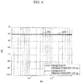
- FIG. 6 is a graph illustrating frequency characteristics after the signal processing for a far sound source in an embodiment.
- Line 200 indicates a signal output from microphone 20a when speaking person 1 located far from microphone 20a makes a voice.
- Line 400 indicates a signal output from filtering processor 50 when speaking person 1 located far from microphone 20a makes a voice. As the voice output from speaking person 1, white noise is adopted.
- m'1(t) denote a signal output from microphone 20a when speaking person 1 located far from microphone 20a makes a voice
- m'2(t) denote a signal output from microphone 20b when speaking person 1 located far from microphone 20a makes a voice
- t indicates a sample of discrete time.
- delay time ⁇ denote a difference in time between a time when the voice made by speaking person 1 arrives at microphone 20a and a time when the voice made by speaking person 1 arrives at microphone 20b.
- G denote a gain that gain controller 30 gives to m'1(t).
- y2(t) denote the signal output from filtering processor 50.
- the sign * indicates the filter processing and h( ⁇ ) indicates a filter that delays a signal by time length ⁇ .
- Gain G is determined as described above.
- the processing by filtering processor 50 makes the voice made by speaking person 1 and input to microphone 20b coincide in phase with the voice made by speaking person 1 and input to microphone 20a.
- a sound pressure level of signal y2(t) has a value that is substantially the same as a value of a sound pressure level of m'1(t). This is because there is little difference in sound pressure level between m'1(t) and m'2(t).
- the reason that m'1(t) and m'2(t) makes the little difference in sound pressure level is that a difference between the distance between speaking person 1 and microphone 20a and the distance between speaking person 1 and microphone 20b has a low ratio to the distance between speaking person 1 and microphone 20a or the distance between speaking person 1 and microphone 20b.
- the sound pressure level of signal y2(t) is not equal to about zero.
- the sound pressure level of signal y2(t) is substantially equal to signal m'1(t).
- line 200 indicates -40 dB
- line 400 also indicates -40 dB. That is, the voice made by speaking person 1 is not suppressed by the signal processing method according to the present disclosure.
- the distance between speaking person 1 and microphone 20a is 50 cm
- the distance between microphone 20a and microphone 20b is 1 cm
- the distance between speaking person 1 and microphone 20b is 51 cm.
- gain G by which signal m'2(t) is multiplied is two.
- the sound pressure level of signal m'2(t) is 50/51 of the sound pressure level of signal m'1(t). Therefore, by being multiplied by the gain being two, the sound pressure level of signal m'2(t) is substantially about twice the sound pressure level of signal m'1(t).
- delayer 40 delays signal m'1(t) by a delay time that is equal to a difference in time between a time when the voice made by speaking person 1 arrives at microphone 20a and a time when the voice made by speaking person 1 arrives at microphone 20b, so that signal m'1(t) and signal m'2(t) are made to coincide in phase. Subtracting the signal m'1(t) that coincides in phase with the signal m'2(t) from the signal m'2(t) given the gain being two therefore makes a sound pressure of the signal representing the voice made by speaking person 1 close to a sound pressure of signal m'1(t) or signal m'2(t). As a result, the signal processing method according to an aspect of the present disclosure does not suppress the signal representing the voice made by speaking person 1.
- the signal processing method enables a blind spot to be formed within a range of a predetermined distance or shorter in sound collection using a plurality of microphones.
- FIG. 7 is a diagram illustrating a specific example of an emergency call system (e-call) to which the signal processing method according to the present disclosure in an embodiment is applied.
- Emergency call system 90 includes loudspeaker 91, microphone 92a, microphone 92b, and button 93.
- emergency call system 90 may be a module having a box shape such as a rectangular parallelepiped.
- the shape of emergency call system 90 is not limited to the above shape.
- Emergency call system 90 may have a box shape such as a cube, a shape such as a polyhedron, or a cylindrical or spherical shape.
- a user can press button 93 to signal the emergency.
- the user can then transmit voice to an operator or the like with microphone 92a and microphone 93b.
- the user can hear voice of the operator or the like from loudspeaker 91.
- Emergency call system 90 is a relatively small module, and thus loudspeaker 91 is also small.
- loudspeaker 91, microphone 92a, and microphone 92b are disposed close to each other.
- a positional relation among loudspeaker 91, microphone 92a, and microphone 92b in emergency call system 90 is similar to the positional relation among loudspeaker 10a, microphone 20a, and microphone 20b in the signal processing device according to an aspect of the present disclosure.
- FIG. 8 is a diagram illustrating how the emergency call system (e-call) to which the signal processing method according to the present disclosure in an embodiment is applied is set up in a vehicle interior.
- emergency call system 90 is attached to a ceiling between a driver's seat and a front passenger seat in the vehicle interior.
- emergency call system 90 is set up in a vicinity of a place between the driver's seat and the front passenger seat in the vehicle interior where a room lamp or the like is set up.
- the place where emergency call system 90 is set up is not limited to the ceiling.
- Emergency call system 90 may be attached to a dashboard in the vehicle interior.
- loudspeaker 91 In emergency call system 90, microphone 92a and microphone 92b are set up close to each other. In emergency call system 90, loudspeaker 91 is also set up close to microphone 92a and microphone 92b. Distances among loudspeaker 91, microphone 92a, and microphone 92b are several millimeters to several centimeters. In contrast, driver 94 who is to make a voice to loudspeaker 91 is away from microphone 92a and microphone 92b. Specifically, driver 94 is located at a distance of several tens of centimeters from microphone 92a and microphone 92b.
- a positional relation among loudspeaker 91, microphone 92a, microphone 92b, and driver 94 in emergency call system 90 is similar to the positional relation among loudspeaker 10a, microphone 20a, microphone 20b, and speaking person 1 in the signal processing device according to an aspect of the present disclosure.
- the configuration of signal processing device 2 illustrated in FIG. 2 includes the two microphones, microphone 20a and microphone 20b, but is not limited to this.
- the number of the microphones may be M (M is an integer equal to or greater than two).
- the M microphones include at least two microphones having different distances from loudspeaker 10a.
- the number of microphones is M
- two of the M microphones may be selected, and the configuration illustrated in FIG. 2 to FIG. 4 may be applied to the two microphones.
- a plurality of sets of two microphones may be selected, and the configuration illustrated in FIG. 2 to FIG. 4 may be applied to each of the plurality of sets.
- a microphone located closest to loudspeaker 10a is connected to the delayer.
- (M - 1) microphones other than the microphone closest to loudspeaker 10a are connected to delayers and gain controllers, respectively.
- the filtering processor performs the filter processing on signals that are output from the (M - 1) microphone other than the microphone closest to loudspeaker 10a, input to the (M - 1) delayers, then output from the (M - 1) delayers, further input to the (M - 1) gain controllers, and then output from the (M - 1) gain controllers and a signal that is output from the microphone located closest to loudspeaker 10a, input to the delayer, and then output from the delayer.
- the signals subjected to the filter processing are input to output destination 10b and output from output destination 10b.
- the signals that are output from the (M - 1) microphone other than the microphone closest to loudspeaker 10a, input to the (M - 1) delayers, then output from the (M - 1) delayers, further input to the (M - 1) gain controllers, and then output from the (M - 1) gain controllers may be signals output from the (M - 1) microphones other than the microphone closest to loudspeaker 10a, input to the (M - 1) gain controllers, then output from the (M - 1) gain controllers, further input to the (M - 1) delayers, and then output from the (M - 1) delayers.
- the filter processing performed here may be a process of, for example, multiplying the signals output from the (M - 1) microphones other than the microphone closest to loudspeaker 10a by a value of an appropriate gain so that a sum of sound pressure levels of the signals output from the (M - 1) microphones other than the microphone closest to loudspeaker 10a is equal to a sound pressure level of the signal that is output from the microphone located closest to loudspeaker 10a, input to the delayer, and then output from the delayer.
- the filter processing subsequently performed here may be a process of subtracting the signals that are output from the (M - 1) microphone other than the microphone closest to loudspeaker 10a, input to the (M - 1) delayers, then output from the (M - 1) delayers, further input to the (M - 1) gain controllers, and then output from the (M - 1) gain controllers, from the signal that is output from the microphone located closest to loudspeaker 10a, input to the delayer, and then output from the delayer.
- the filter processing subsequently performed here may be a process of subtracting the signal that is output from the microphone located closest to loudspeaker 10a, input to the delayer, and then output from the delayer, from the signals that are output from the (M - 1) microphones other than the microphone closest to loudspeaker 10a, input to the (M - 1) delayers, then output from the (M - 1) delayers, further input to the (M - 1) gain controllers, and then output from the (M - 1) gain controllers.
- the filter processing performed here may be a process of subtracting the signals that are output from the (M - 1) microphone other than the microphone closest to loudspeaker 10a, input to the (M - 1) delayers, then output from the (M - 1) delayers, further input to the (M - 1) gain controllers, and then output from the (M - 1) gain controllers, from the signal that is output from the microphone located closest to loudspeaker 10a, input to the delayer, then output from the delayer, and multiplied by M.
- the filter processing performed here may be a process of another kind that can suppress signals representing an output sound from loudspeaker 10a collected by the M microphones, using the signals output from the M microphones.
- signal processing device 2 may have the above configuration for each of N sound sources (loudspeakers, etc.) (N is an integer equal to or greater than two).
- the configuration of signal processing device 3 illustrated in FIG. 3 includes the two microphones, microphone 20a and microphone 20b, but is not limited to this.
- the number of the microphones may be M (M is an integer equal to or greater than two).
- M is an integer equal to or greater than two.
- M is an integer equal to or greater than two.
- the filtering processor performs the filter processing on signals that are output from the (M - 1) microphone other than the microphone closest to loudspeaker 10a, go through the frequency converters, are input to the (M - 1) delayers, then output from the (M - 1) delayers, further input to the (M - 1) gain controllers, and then output from the (M - 1) gain controllers and a signal that is output from the microphone located closest to loudspeaker 10a, goes through the frequency converter, is input to the delayer, and then output from the delayer.
- the signals subjected to the filter processing are input to the time signal converter, output from the time signal converter, then input to output destination 10b, and output from output destination 10b.
- the signals that are output from the (M - 1) microphone other than the microphone closest to loudspeaker 10a, go through the frequency converters, are input to the (M - 1) delayers, then output from the (M - 1) delayers, further input to the (M - 1) gain controllers, and then output from the (M - 1) gain controllers may be signals that are output from the (M - 1) microphones other than the microphone closest to loudspeaker 10a, go through the frequency converters, are input to the (M - 1) gain controllers, then output from the (M - 1) gain controllers, further input to the (M - 1) delayers, and then output from the (M - 1) delayers.
- the filter processing performed here may be a process of, for example, multiplying the signals that are output from the (M - 1) microphones other than the microphone closest to loudspeaker 10a and go through the frequency converters by a value of an appropriate gain so that a sum of sound pressure levels of the signals that are output from the (M - 1) microphones other than the microphone closest to loudspeaker 10a and go through the frequency converters is equal to a sound pressure level of the signal that is output from the microphone located closest to loudspeaker 10a, goes through the frequency converter, is input to the delayer, and then output from the delayer.
- the filter processing subsequently performed here may be a process of subtracting the signals that are output from the (M - 1) microphone other than the microphone closest to loudspeaker 10a, go through the frequency converters, are input to the (M - 1) delayers, then output from the (M - 1) delayers, further input to the (M - 1) gain controllers, and then output from the (M - 1) gain controllers, from the signal that is output from the microphone located closest to loudspeaker 10a, goes through the frequency converter, is input to the delayer, and then output from the delayer.
- the filter processing subsequently performed here may be a process of subtracting the signal that is output from the microphone located closest to loudspeaker 10a, goes through the frequency converter, is input to the delayer, and then output from the delayer, from the signals that are output from the (M - 1) microphone other than the microphone closest to loudspeaker 10a, go through the frequency converters, are input to the (M - 1) delayers, then output from the (M - 1) delayers, further input to the (M - 1) gain controllers, and then output from the (M - 1) gain controllers.
- the filter processing performed here may be a process of subtracting the signals that are output from the (M - 1) microphone other than the microphone closest to loudspeaker 10a, go through the frequency converters, are input to the (M - 1) delayers, then output from the (M - 1) delayers, further input to the (M - 1) gain controllers, and then output from the (M - 1) gain controllers, from the signal that is output from the microphone located closest to loudspeaker 10a, goes through the frequency converter, is input to the delayer, then output from the delayer, and multiplied by M.
- the filter processing performed here may be a process of another kind that can suppress signals representing an output sound from loudspeaker 10a collected by the M microphones, using the signals output from the M microphones.
- signal processing device 3 may have the above configuration for each of N sound sources (loudspeakers, etc.) (N is an integer equal to or greater than two).
- each of the structural elements may be configured in the form of an exclusive hardware product, or may be implemented by executing a software program suitable for the structural element.
- Each of the structural elements may be implemented by means of a program execution unit, such as a CPU or a processor, reading and executing a software program recorded on a recording medium such as a hard disk or a semiconductor memory.
- signal processing device 2 and signal processing device 3 may each include processing circuitry and storage which is electrically connected to the processing circuitry and accessible from the processing circuitry.
- the processing circuitry includes at least one of an exclusive hardware product and a program execution unit, and performs processing using the storage.
- the processing circuitry includes a program execution unit
- the storage stores a software program executed by the program execution unit.
- the software for implementing the signal processing method according to the present embodiment includes a program as below.
- the program may cause a computer to execute a signal processing method including: multiplying at least one of M signals output from M microphones by a gain so as to equalize sound pressure levels of the M signals, the M signals representing sounds that arrive at the M microphones from a sound source located within a predetermined distance from the M microphones, M being an integer equal to or greater than two; delaying at least one of the M signals so as to resolve time discrepancies between the M signals, the time discrepancies being caused by differences in arrival time between sounds that arrive at the M microphones from the sound source; and applying a filter to the M signals that are obtained through the multiplying and the delaying, so as to generate a signal in which a sound output from the sound source located within the predetermined distance is suppressed, wherein the sound source is located within the predetermined distance from a microphone included in the M microphones which is located closest to the sound source.
- the structural elements may be circuits as described above.
- the circuits may constitute circuitry as a whole, or may be individual circuits.
- Each structural element may be implemented by a general processor, or may be implemented by an exclusive processor.
- processing executed by a particular structural element may be executed by another structural element.
- the present disclosure is applicable to, for example, an emergency call system (e-call), a smartphone, a video conference system, or a microphone and a loudspeaker used in conference.
- e-call emergency call system
- smartphone a smartphone
- video conference system or a microphone and a loudspeaker used in conference.
Landscapes
- Health & Medical Sciences (AREA)
- Otolaryngology (AREA)
- Engineering & Computer Science (AREA)
- Signal Processing (AREA)
- Physics & Mathematics (AREA)
- Acoustics & Sound (AREA)
- General Health & Medical Sciences (AREA)
- Circuit For Audible Band Transducer (AREA)
Applications Claiming Priority (2)
| Application Number | Priority Date | Filing Date | Title |
|---|---|---|---|
| US201862724234P | 2018-08-29 | 2018-08-29 | |
| JP2019078676A JP2020036304A (ja) | 2018-08-29 | 2019-04-17 | 信号処理方法及び信号処理装置 |
Publications (3)
| Publication Number | Publication Date |
|---|---|
| EP3627851A2 true EP3627851A2 (fr) | 2020-03-25 |
| EP3627851A3 EP3627851A3 (fr) | 2020-04-22 |
| EP3627851B1 EP3627851B1 (fr) | 2021-05-19 |
Family
ID=67810365
Family Applications (1)
| Application Number | Title | Priority Date | Filing Date |
|---|---|---|---|
| EP19193581.6A Active EP3627851B1 (fr) | 2018-08-29 | 2019-08-26 | Procédé et dispositif de traitement de signal |
Country Status (2)
| Country | Link |
|---|---|
| US (1) | US10708702B2 (fr) |
| EP (1) | EP3627851B1 (fr) |
Families Citing this family (6)
| Publication number | Priority date | Publication date | Assignee | Title |
|---|---|---|---|---|
| JP7184527B2 (ja) * | 2018-03-20 | 2022-12-06 | トヨタ自動車株式会社 | マイク・スピーカ一体装置及び車両 |
| CN114556970B (zh) * | 2019-10-10 | 2024-02-20 | 深圳市韶音科技有限公司 | 音响设备 |
| US12267655B2 (en) | 2021-01-21 | 2025-04-01 | Biamp Systems, LLC | Automated audio tuning launch procedure and report |
| US11742815B2 (en) | 2021-01-21 | 2023-08-29 | Biamp Systems, LLC | Analyzing and determining conference audio gain levels |
| US12192737B2 (en) | 2021-11-08 | 2025-01-07 | Biamp Systems, LLC | Automated audio tuning and compensation procedure |
| EP4513902A1 (fr) * | 2023-08-22 | 2025-02-26 | Oticon A/s | Émulation améliorée de perte auditive par l'intermédiaire de réseaux neuronaux |
Citations (2)
| Publication number | Priority date | Publication date | Assignee | Title |
|---|---|---|---|---|
| JPS5123595B1 (fr) | 1969-10-01 | 1976-07-17 | ||
| JP5486694B2 (ja) | 2010-12-21 | 2014-05-07 | 日本電信電話株式会社 | 音声強調方法、装置、プログラム、記録媒体 |
Family Cites Families (11)
| Publication number | Priority date | Publication date | Assignee | Title |
|---|---|---|---|---|
| JP3541339B2 (ja) * | 1997-06-26 | 2004-07-07 | 富士通株式会社 | マイクロホンアレイ装置 |
| US7577262B2 (en) | 2002-11-18 | 2009-08-18 | Panasonic Corporation | Microphone device and audio player |
| JP4247002B2 (ja) | 2003-01-22 | 2009-04-02 | 富士通株式会社 | マイクロホンアレイを用いた話者距離検出装置及び方法並びに当該装置を用いた音声入出力装置 |
| JP2005341384A (ja) * | 2004-05-28 | 2005-12-08 | Sony Corp | 音場補正装置、音場補正方法 |
| EP1640971B1 (fr) | 2004-09-23 | 2008-08-20 | Harman Becker Automotive Systems GmbH | Traitement adaptatif d'un signal de parole multicanaux avec suppression du bruit |
| JP4285457B2 (ja) * | 2005-07-20 | 2009-06-24 | ソニー株式会社 | 音場測定装置及び音場測定方法 |
| JP5123595B2 (ja) | 2007-07-31 | 2013-01-23 | 独立行政法人情報通信研究機構 | 近傍場音源分離プログラム、及びこのプログラムを記録したコンピュータ読取可能な記録媒体、並びに近傍場音源分離方法 |
| CN101569209B (zh) | 2007-10-04 | 2013-08-21 | 松下电器产业株式会社 | 噪声抽取装置和方法、麦克风装置、集成电路以及摄像机 |
| EP2938098B1 (fr) * | 2012-12-21 | 2019-04-03 | Panasonic Intellectual Property Management Co., Ltd. | Dispositif de microphones directionnels, procédé et programme de traitement de signaux audio |
| JP6311430B2 (ja) * | 2014-04-23 | 2018-04-18 | ヤマハ株式会社 | 音響処理装置 |
| US9894434B2 (en) * | 2015-12-04 | 2018-02-13 | Sennheiser Electronic Gmbh & Co. Kg | Conference system with a microphone array system and a method of speech acquisition in a conference system |
-
2019
- 2019-08-16 US US16/543,047 patent/US10708702B2/en active Active
- 2019-08-26 EP EP19193581.6A patent/EP3627851B1/fr active Active
Patent Citations (2)
| Publication number | Priority date | Publication date | Assignee | Title |
|---|---|---|---|---|
| JPS5123595B1 (fr) | 1969-10-01 | 1976-07-17 | ||
| JP5486694B2 (ja) | 2010-12-21 | 2014-05-07 | 日本電信電話株式会社 | 音声強調方法、装置、プログラム、記録媒体 |
Also Published As
| Publication number | Publication date |
|---|---|
| US20200077214A1 (en) | 2020-03-05 |
| EP3627851A3 (fr) | 2020-04-22 |
| EP3627851B1 (fr) | 2021-05-19 |
| US10708702B2 (en) | 2020-07-07 |
Similar Documents
| Publication | Publication Date | Title |
|---|---|---|
| EP3627851B1 (fr) | Procédé et dispositif de traitement de signal | |
| JP6196320B2 (ja) | 複数の瞬間到来方向推定を用いるインフォ−ムド空間フィルタリングのフィルタおよび方法 | |
| CN111128210B (zh) | 具有声学回声消除的音频信号处理的方法和系统 | |
| US10123113B2 (en) | Selective audio source enhancement | |
| US8958572B1 (en) | Adaptive noise cancellation for multi-microphone systems | |
| US8345890B2 (en) | System and method for utilizing inter-microphone level differences for speech enhancement | |
| KR101449433B1 (ko) | 마이크로폰을 통해 입력된 사운드 신호로부터 잡음을제거하는 방법 및 장치 | |
| CA2908180C (fr) | Appareil et procede de generation d'un signal de sortie au moyen d'un decomposeur | |
| JP6870078B2 (ja) | 動的サウンド調整のための雑音推定 | |
| CN112820310B (zh) | 一种来波方向估计方法及装置 | |
| EP3050322B1 (fr) | Système et procédé pour évaluer une fonction de transfert acoustique | |
| US8639499B2 (en) | Formant aided noise cancellation using multiple microphones | |
| CN108717495A (zh) | 多波束波束成形的方法、装置及电子设备 | |
| JP7124506B2 (ja) | 集音拡声装置、その方法、およびプログラム | |
| CN112951261B (zh) | 声源定位方法、装置及语音设备 | |
| CN110876097B (zh) | 信号处理方法、信号处理装置以及记录介质 | |
| US11765504B2 (en) | Input signal decorrelation | |
| CN111863018A (zh) | 一种双麦克风下的定向拾音方法及相关装置 | |
| CN113519169A (zh) | 用于音频啸叫衰减的方法和装置 | |
| Saremi | Spatial Audio Signal Processing for Speech Telecommunication | |
| JP2015070292A (ja) | 集音・放音装置及び集音・放音プログラム | |
| JP2015070291A (ja) | 集音・放音装置、音源分離ユニット及び音源分離プログラム | |
| JP7147849B2 (ja) | 集音拡声装置、その方法、およびプログラム | |
| JP7636512B2 (ja) | ポータブルカラオケの低複雑度ハウリング抑制 | |
| Kowalczyk | Multichannel Wiener filter with early reflection raking for automatic speech recognition in presence of reverberation |
Legal Events
| Date | Code | Title | Description |
|---|---|---|---|
| PUAI | Public reference made under article 153(3) epc to a published international application that has entered the european phase |
Free format text: ORIGINAL CODE: 0009012 |
|
| STAA | Information on the status of an ep patent application or granted ep patent |
Free format text: STATUS: THE APPLICATION HAS BEEN PUBLISHED |
|
| PUAL | Search report despatched |
Free format text: ORIGINAL CODE: 0009013 |
|
| AK | Designated contracting states |
Kind code of ref document: A2 Designated state(s): AL AT BE BG CH CY CZ DE DK EE ES FI FR GB GR HR HU IE IS IT LI LT LU LV MC MK MT NL NO PL PT RO RS SE SI SK SM TR |
|
| AX | Request for extension of the european patent |
Extension state: BA ME |
|
| AK | Designated contracting states |
Kind code of ref document: A3 Designated state(s): AL AT BE BG CH CY CZ DE DK EE ES FI FR GB GR HR HU IE IS IT LI LT LU LV MC MK MT NL NO PL PT RO RS SE SI SK SM TR |
|
| AX | Request for extension of the european patent |
Extension state: BA ME |
|
| RIC1 | Information provided on ipc code assigned before grant |
Ipc: H04R 1/40 20060101AFI20200313BHEP Ipc: H04M 9/08 20060101ALI20200313BHEP Ipc: H04R 3/02 20060101ALN20200313BHEP Ipc: H04R 3/00 20060101ALI20200313BHEP |
|
| STAA | Information on the status of an ep patent application or granted ep patent |
Free format text: STATUS: REQUEST FOR EXAMINATION WAS MADE |
|
| 17P | Request for examination filed |
Effective date: 20201021 |
|
| RBV | Designated contracting states (corrected) |
Designated state(s): AL AT BE BG CH CY CZ DE DK EE ES FI FR GB GR HR HU IE IS IT LI LT LU LV MC MK MT NL NO PL PT RO RS SE SI SK SM TR |
|
| GRAP | Despatch of communication of intention to grant a patent |
Free format text: ORIGINAL CODE: EPIDOSNIGR1 |
|
| STAA | Information on the status of an ep patent application or granted ep patent |
Free format text: STATUS: GRANT OF PATENT IS INTENDED |
|
| RIC1 | Information provided on ipc code assigned before grant |
Ipc: H04R 3/02 20060101ALN20210118BHEP Ipc: H04R 3/00 20060101ALI20210118BHEP Ipc: H04M 9/08 20060101ALI20210118BHEP Ipc: H04R 1/40 20060101AFI20210118BHEP |
|
| INTG | Intention to grant announced |
Effective date: 20210209 |
|
| GRAS | Grant fee paid |
Free format text: ORIGINAL CODE: EPIDOSNIGR3 |
|
| GRAA | (expected) grant |
Free format text: ORIGINAL CODE: 0009210 |
|
| STAA | Information on the status of an ep patent application or granted ep patent |
Free format text: STATUS: THE PATENT HAS BEEN GRANTED |
|
| AK | Designated contracting states |
Kind code of ref document: B1 Designated state(s): AL AT BE BG CH CY CZ DE DK EE ES FI FR GB GR HR HU IE IS IT LI LT LU LV MC MK MT NL NO PL PT RO RS SE SI SK SM TR |
|
| REG | Reference to a national code |
Ref country code: GB Ref legal event code: FG4D |
|
| REG | Reference to a national code |
Ref country code: CH Ref legal event code: EP |
|
| REG | Reference to a national code |
Ref country code: DE Ref legal event code: R096 Ref document number: 602019004695 Country of ref document: DE |
|
| REG | Reference to a national code |
Ref country code: AT Ref legal event code: REF Ref document number: 1395160 Country of ref document: AT Kind code of ref document: T Effective date: 20210615 |
|
| REG | Reference to a national code |
Ref country code: IE Ref legal event code: FG4D |
|
| REG | Reference to a national code |
Ref country code: LT Ref legal event code: MG9D |
|
| REG | Reference to a national code |
Ref country code: AT Ref legal event code: MK05 Ref document number: 1395160 Country of ref document: AT Kind code of ref document: T Effective date: 20210519 |
|
| REG | Reference to a national code |
Ref country code: NL Ref legal event code: MP Effective date: 20210519 |
|
| PG25 | Lapsed in a contracting state [announced via postgrant information from national office to epo] |
Ref country code: BG Free format text: LAPSE BECAUSE OF FAILURE TO SUBMIT A TRANSLATION OF THE DESCRIPTION OR TO PAY THE FEE WITHIN THE PRESCRIBED TIME-LIMIT Effective date: 20210819 Ref country code: AT Free format text: LAPSE BECAUSE OF FAILURE TO SUBMIT A TRANSLATION OF THE DESCRIPTION OR TO PAY THE FEE WITHIN THE PRESCRIBED TIME-LIMIT Effective date: 20210519 Ref country code: HR Free format text: LAPSE BECAUSE OF FAILURE TO SUBMIT A TRANSLATION OF THE DESCRIPTION OR TO PAY THE FEE WITHIN THE PRESCRIBED TIME-LIMIT Effective date: 20210519 Ref country code: LT Free format text: LAPSE BECAUSE OF FAILURE TO SUBMIT A TRANSLATION OF THE DESCRIPTION OR TO PAY THE FEE WITHIN THE PRESCRIBED TIME-LIMIT Effective date: 20210519 Ref country code: FI Free format text: LAPSE BECAUSE OF FAILURE TO SUBMIT A TRANSLATION OF THE DESCRIPTION OR TO PAY THE FEE WITHIN THE PRESCRIBED TIME-LIMIT Effective date: 20210519 |
|
| PG25 | Lapsed in a contracting state [announced via postgrant information from national office to epo] |
Ref country code: GR Free format text: LAPSE BECAUSE OF FAILURE TO SUBMIT A TRANSLATION OF THE DESCRIPTION OR TO PAY THE FEE WITHIN THE PRESCRIBED TIME-LIMIT Effective date: 20210820 Ref country code: IS Free format text: LAPSE BECAUSE OF FAILURE TO SUBMIT A TRANSLATION OF THE DESCRIPTION OR TO PAY THE FEE WITHIN THE PRESCRIBED TIME-LIMIT Effective date: 20210919 Ref country code: PL Free format text: LAPSE BECAUSE OF FAILURE TO SUBMIT A TRANSLATION OF THE DESCRIPTION OR TO PAY THE FEE WITHIN THE PRESCRIBED TIME-LIMIT Effective date: 20210519 Ref country code: NO Free format text: LAPSE BECAUSE OF FAILURE TO SUBMIT A TRANSLATION OF THE DESCRIPTION OR TO PAY THE FEE WITHIN THE PRESCRIBED TIME-LIMIT Effective date: 20210819 Ref country code: LV Free format text: LAPSE BECAUSE OF FAILURE TO SUBMIT A TRANSLATION OF THE DESCRIPTION OR TO PAY THE FEE WITHIN THE PRESCRIBED TIME-LIMIT Effective date: 20210519 Ref country code: PT Free format text: LAPSE BECAUSE OF FAILURE TO SUBMIT A TRANSLATION OF THE DESCRIPTION OR TO PAY THE FEE WITHIN THE PRESCRIBED TIME-LIMIT Effective date: 20210920 Ref country code: RS Free format text: LAPSE BECAUSE OF FAILURE TO SUBMIT A TRANSLATION OF THE DESCRIPTION OR TO PAY THE FEE WITHIN THE PRESCRIBED TIME-LIMIT Effective date: 20210519 Ref country code: SE Free format text: LAPSE BECAUSE OF FAILURE TO SUBMIT A TRANSLATION OF THE DESCRIPTION OR TO PAY THE FEE WITHIN THE PRESCRIBED TIME-LIMIT Effective date: 20210519 |
|
| PG25 | Lapsed in a contracting state [announced via postgrant information from national office to epo] |
Ref country code: NL Free format text: LAPSE BECAUSE OF FAILURE TO SUBMIT A TRANSLATION OF THE DESCRIPTION OR TO PAY THE FEE WITHIN THE PRESCRIBED TIME-LIMIT Effective date: 20210519 |
|
| PG25 | Lapsed in a contracting state [announced via postgrant information from national office to epo] |
Ref country code: DK Free format text: LAPSE BECAUSE OF FAILURE TO SUBMIT A TRANSLATION OF THE DESCRIPTION OR TO PAY THE FEE WITHIN THE PRESCRIBED TIME-LIMIT Effective date: 20210519 Ref country code: CZ Free format text: LAPSE BECAUSE OF FAILURE TO SUBMIT A TRANSLATION OF THE DESCRIPTION OR TO PAY THE FEE WITHIN THE PRESCRIBED TIME-LIMIT Effective date: 20210519 Ref country code: RO Free format text: LAPSE BECAUSE OF FAILURE TO SUBMIT A TRANSLATION OF THE DESCRIPTION OR TO PAY THE FEE WITHIN THE PRESCRIBED TIME-LIMIT Effective date: 20210519 Ref country code: SM Free format text: LAPSE BECAUSE OF FAILURE TO SUBMIT A TRANSLATION OF THE DESCRIPTION OR TO PAY THE FEE WITHIN THE PRESCRIBED TIME-LIMIT Effective date: 20210519 Ref country code: SK Free format text: LAPSE BECAUSE OF FAILURE TO SUBMIT A TRANSLATION OF THE DESCRIPTION OR TO PAY THE FEE WITHIN THE PRESCRIBED TIME-LIMIT Effective date: 20210519 Ref country code: ES Free format text: LAPSE BECAUSE OF FAILURE TO SUBMIT A TRANSLATION OF THE DESCRIPTION OR TO PAY THE FEE WITHIN THE PRESCRIBED TIME-LIMIT Effective date: 20210519 Ref country code: EE Free format text: LAPSE BECAUSE OF FAILURE TO SUBMIT A TRANSLATION OF THE DESCRIPTION OR TO PAY THE FEE WITHIN THE PRESCRIBED TIME-LIMIT Effective date: 20210519 |
|
| REG | Reference to a national code |
Ref country code: DE Ref legal event code: R097 Ref document number: 602019004695 Country of ref document: DE |
|
| PLBE | No opposition filed within time limit |
Free format text: ORIGINAL CODE: 0009261 |
|
| STAA | Information on the status of an ep patent application or granted ep patent |
Free format text: STATUS: NO OPPOSITION FILED WITHIN TIME LIMIT |
|
| PG25 | Lapsed in a contracting state [announced via postgrant information from national office to epo] |
Ref country code: MC Free format text: LAPSE BECAUSE OF FAILURE TO SUBMIT A TRANSLATION OF THE DESCRIPTION OR TO PAY THE FEE WITHIN THE PRESCRIBED TIME-LIMIT Effective date: 20210519 |
|
| REG | Reference to a national code |
Ref country code: BE Ref legal event code: MM Effective date: 20210831 |
|
| 26N | No opposition filed |
Effective date: 20220222 |
|
| PG25 | Lapsed in a contracting state [announced via postgrant information from national office to epo] |
Ref country code: IS Free format text: LAPSE BECAUSE OF FAILURE TO SUBMIT A TRANSLATION OF THE DESCRIPTION OR TO PAY THE FEE WITHIN THE PRESCRIBED TIME-LIMIT Effective date: 20210919 Ref country code: LU Free format text: LAPSE BECAUSE OF NON-PAYMENT OF DUE FEES Effective date: 20210826 Ref country code: AL Free format text: LAPSE BECAUSE OF FAILURE TO SUBMIT A TRANSLATION OF THE DESCRIPTION OR TO PAY THE FEE WITHIN THE PRESCRIBED TIME-LIMIT Effective date: 20210519 |
|
| PG25 | Lapsed in a contracting state [announced via postgrant information from national office to epo] |
Ref country code: IT Free format text: LAPSE BECAUSE OF FAILURE TO SUBMIT A TRANSLATION OF THE DESCRIPTION OR TO PAY THE FEE WITHIN THE PRESCRIBED TIME-LIMIT Effective date: 20210519 Ref country code: IE Free format text: LAPSE BECAUSE OF NON-PAYMENT OF DUE FEES Effective date: 20210826 Ref country code: FR Free format text: LAPSE BECAUSE OF NON-PAYMENT OF DUE FEES Effective date: 20210831 Ref country code: BE Free format text: LAPSE BECAUSE OF NON-PAYMENT OF DUE FEES Effective date: 20210831 |
|
| REG | Reference to a national code |
Ref country code: CH Ref legal event code: PL |
|
| PG25 | Lapsed in a contracting state [announced via postgrant information from national office to epo] |
Ref country code: LI Free format text: LAPSE BECAUSE OF NON-PAYMENT OF DUE FEES Effective date: 20220831 Ref country code: CH Free format text: LAPSE BECAUSE OF NON-PAYMENT OF DUE FEES Effective date: 20220831 |
|
| PG25 | Lapsed in a contracting state [announced via postgrant information from national office to epo] |
Ref country code: CY Free format text: LAPSE BECAUSE OF FAILURE TO SUBMIT A TRANSLATION OF THE DESCRIPTION OR TO PAY THE FEE WITHIN THE PRESCRIBED TIME-LIMIT Effective date: 20210519 |
|
| PG25 | Lapsed in a contracting state [announced via postgrant information from national office to epo] |
Ref country code: HU Free format text: LAPSE BECAUSE OF FAILURE TO SUBMIT A TRANSLATION OF THE DESCRIPTION OR TO PAY THE FEE WITHIN THE PRESCRIBED TIME-LIMIT; INVALID AB INITIO Effective date: 20190826 |
|
| GBPC | Gb: european patent ceased through non-payment of renewal fee |
Effective date: 20230826 |
|
| PG25 | Lapsed in a contracting state [announced via postgrant information from national office to epo] |
Ref country code: MK Free format text: LAPSE BECAUSE OF FAILURE TO SUBMIT A TRANSLATION OF THE DESCRIPTION OR TO PAY THE FEE WITHIN THE PRESCRIBED TIME-LIMIT Effective date: 20210519 |
|
| PG25 | Lapsed in a contracting state [announced via postgrant information from national office to epo] |
Ref country code: GB Free format text: LAPSE BECAUSE OF NON-PAYMENT OF DUE FEES Effective date: 20230826 |
|
| PG25 | Lapsed in a contracting state [announced via postgrant information from national office to epo] |
Ref country code: GB Free format text: LAPSE BECAUSE OF NON-PAYMENT OF DUE FEES Effective date: 20230826 |
|
| PG25 | Lapsed in a contracting state [announced via postgrant information from national office to epo] |
Ref country code: MT Free format text: LAPSE BECAUSE OF FAILURE TO SUBMIT A TRANSLATION OF THE DESCRIPTION OR TO PAY THE FEE WITHIN THE PRESCRIBED TIME-LIMIT Effective date: 20210519 |
|
| PGFP | Annual fee paid to national office [announced via postgrant information from national office to epo] |
Ref country code: DE Payment date: 20250820 Year of fee payment: 7 |
|
| PG25 | Lapsed in a contracting state [announced via postgrant information from national office to epo] |
Ref country code: TR Free format text: LAPSE BECAUSE OF FAILURE TO SUBMIT A TRANSLATION OF THE DESCRIPTION OR TO PAY THE FEE WITHIN THE PRESCRIBED TIME-LIMIT Effective date: 20210519 |