EP3627986B1 - Dispositif de circulation pour solutions hydroponiques - Google Patents
Dispositif de circulation pour solutions hydroponiques Download PDFInfo
- Publication number
- EP3627986B1 EP3627986B1 EP19753232.8A EP19753232A EP3627986B1 EP 3627986 B1 EP3627986 B1 EP 3627986B1 EP 19753232 A EP19753232 A EP 19753232A EP 3627986 B1 EP3627986 B1 EP 3627986B1
- Authority
- EP
- European Patent Office
- Prior art keywords
- nutrient
- grow
- tank
- nafc
- supply
- Prior art date
- Legal status (The legal status is an assumption and is not a legal conclusion. Google has not performed a legal analysis and makes no representation as to the accuracy of the status listed.)
- Active
Links
Images


Classifications
-
- A—HUMAN NECESSITIES
- A01—AGRICULTURE; FORESTRY; ANIMAL HUSBANDRY; HUNTING; TRAPPING; FISHING
- A01G—HORTICULTURE; CULTIVATION OF VEGETABLES, FLOWERS, RICE, FRUIT, VINES, HOPS OR SEAWEED; FORESTRY; WATERING
- A01G31/00—Soilless cultivation, e.g. hydroponics
- A01G31/02—Special apparatus therefor
-
- A—HUMAN NECESSITIES
- A01—AGRICULTURE; FORESTRY; ANIMAL HUSBANDRY; HUNTING; TRAPPING; FISHING
- A01G—HORTICULTURE; CULTIVATION OF VEGETABLES, FLOWERS, RICE, FRUIT, VINES, HOPS OR SEAWEED; FORESTRY; WATERING
- A01G27/00—Self-acting watering devices, e.g. for flower-pots
- A01G27/005—Reservoirs connected to flower-pots through conduits
-
- A—HUMAN NECESSITIES
- A01—AGRICULTURE; FORESTRY; ANIMAL HUSBANDRY; HUNTING; TRAPPING; FISHING
- A01G—HORTICULTURE; CULTIVATION OF VEGETABLES, FLOWERS, RICE, FRUIT, VINES, HOPS OR SEAWEED; FORESTRY; WATERING
- A01G31/00—Soilless cultivation, e.g. hydroponics
- A01G31/02—Special apparatus therefor
- A01G31/065—Special apparatus therefor with means for recycling the nutritive solution
-
- Y—GENERAL TAGGING OF NEW TECHNOLOGICAL DEVELOPMENTS; GENERAL TAGGING OF CROSS-SECTIONAL TECHNOLOGIES SPANNING OVER SEVERAL SECTIONS OF THE IPC; TECHNICAL SUBJECTS COVERED BY FORMER USPC CROSS-REFERENCE ART COLLECTIONS [XRACs] AND DIGESTS
- Y02—TECHNOLOGIES OR APPLICATIONS FOR MITIGATION OR ADAPTATION AGAINST CLIMATE CHANGE
- Y02P—CLIMATE CHANGE MITIGATION TECHNOLOGIES IN THE PRODUCTION OR PROCESSING OF GOODS
- Y02P60/00—Technologies relating to agriculture, livestock or agroalimentary industries
- Y02P60/20—Reduction of greenhouse gas [GHG] emissions in agriculture, e.g. CO2
- Y02P60/21—Dinitrogen oxide [N2O], e.g. using aquaponics, hydroponics or efficiency measures
Definitions
- the present invention relates to hydroponics, and more particularly to hydroponic nutrient circulation systems according to claims 1 and 8.
- Hydroponics is the method of growing plants without soil, using a solution of water and dissolved mineral and/or organic nutrients. Only the roots are immersed in the nutrient solution, and sometimes only the tips of the roots are immersed. Because soil nutrients are not available to the plants, it is critical that all of the necessary nutrients be added and maintained in the correct ratios in the nutrient solution. Hydroponic nutrient solutions must be monitored to ensure that nutrient concentration, oxygen concentration, pH, and temperature are within desired ranges.
- Hydroponic systems are widely used by hobbyists and commercial growers. Growers employ a number of techniques to provide access to nutrients and to maintain the proper nutrient mixture for the plants.
- the solution from each growing tank is returned to the reservoir through gravity return pipelines.
- Automatic keep-full valves maintain reservoir level by adding water to the reservoir as the level drops.
- Proper nutrient mixture, pH, and temperature can be maintained for all of the grow tanks in the network by monitoring and adjusting the reservoir nutrient solution.
- the grow tanks still require aeration, which typically is provided by a large air pump feeding a distribution manifold so that air may be delivered to each grow tank.
- These systems require the grow tanks to be located above the level of the reservoir so that the gravity return lines can be used.
- the multiple grow tanks and the reservoir all are at the same level.
- the grow pots are all connected to a common drain line so that they all have the same liquid level as in the nutrient reservoir.
- a pump in the reservoir delivers nutrient solution to each grow pot to provide a continuous supply of fresh nutrient.
- Air is supplied by way of an air pump with air stones in each grow tank. Drainpipe size is generally large to assure that a common level is maintained in all of the grow tanks and to assure that aggressive roots do not plug the drain ports in the grow tanks.
- the drain piping system must connect the reservoir directly with each grow tank. This requires leak-tight joints for grow tank gravity drain ports to connect with the drain line. Particularly in systems where grow tanks are elevated relative to the reservoir, this can be a complex, three-dimensional network of pipes and joints, thereby adding installation expense and making modifications problematic.
- Reconfiguring pipelines requires a shutdown of the operation, potentially leaving roots exposed to air. Reconfiguring pipelines also can take significant time, which adds to the risk of plant damage.
- Aeration also presents problems. Aeration requires air pumps and lines, which adds cost. Air lines must be routed to all grow tanks adding to the network cost and complexity.
- NFT Net Film Technique
- the grow tanks that employ the hydroponic system known as Net Film Technique use a thin film of liquid nutrient flowing from one end to the other in the bottom of a trough-type tank.
- This type of grow tank is widely used, for example, in commercial vegetable and herb operations.
- Many plants can grow side-by-side along the length of the trough. The plants sit in holes in the cover of the trough with the tips of their roots wetted by the thin layer of flowing nutrient.
- gravity drains in these tanks may allow all nutrient solution to drain out quickly in the event of a power interruption or pump failure. This can result in the loss of an entire crop.
- a hydroponic nutrient aeration and flow control (NAFC) device and system is disclosed herein, which both aerates and controls the flow of the nutrient solution.
- the NAFC device has no moving parts.
- the NAFC device includes a nutrient supply intake, a grow tank return intake, a nozzle communicating with the nutrient supply intake, a mixing chamber in fluid communication with both the nozzle and the grow tank return intake, an outlet port in fluid communication with the mixing chamber and aligned with the nozzle, and a grow tank supply outlet in fluid communication with the outlet port.
- Nutrient from the nutrient reservoir flows into the nutrient supply intake, through the nozzle, and into the mixing chamber.
- Nutrient and/or air from the grow tank drain line is drawn through the grow tank return intake and into the mixing chamber. The two nutrient flows and/or the air are admixed within the mixing chamber, and a portion of the admixture is directed into the outlet port for delivery to the grow tank through the grow tank supply outlet.
- the NAFC system includes an NAFC device within each nutrient supply line to each grow tank. More specifically, the system includes a nutrient reservoir, a plurality of grow tanks, a nutrient supply system for supplying nutrient from the reservoir to the grow tanks, a nutrient return system for returning nutrient from the grow tanks to the nutrient reservoir, and a plurality of NAFC devices - with each NAFC device within one of the nutrient supply lines to one of the grow tanks.
- the NAFC device may be used as a hydroponic nutrient aerator (i.e. without a flow control function).
- the nutrient solution can be mixed, aerated, and circulated to multiple grow tanks from a nutrient reservoir; and the nutrient level in each grow tank may be controlled or adjusted independently of the other grow tanks.
- the need for common drain lines is eliminated, improving safety and plumbing flexibility, and reducing cost.
- the need for holes and leak-tight connections in the grow tanks for nutrient circulation is also eliminated.
- the need for air pumps is further eliminated, reducing system component and installation costs.
- any reference to claim elements as "at least one of X, Y and Z" is meant to include any one or more of X, Y or Z individually, and any combination of any one or more of X, Y and Z, for example, X, Y, Z; X, Y; X, Z ; and Y, Z.
- Embodiments of the hydroponic nutrient aerator and flow control (NAFC) devices are illustrated in the drawings and designated 10 and 310.
- the NAFC devices may be used in two types of hydroponic installations.
- a "Type I” installation includes grow tanks arrayed in proximity to the nutrient reservoir.
- the NAFC devices 10 are mounted to a manifold connected to a reservoir pump.
- a "Type II” installation includes a nutrient reservoir remote from the grow tanks.
- the NAFC devices 310 are distributed throughout the system, with one NAFC device located near each grow tank.
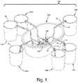
- a Type I system is illustrated in Figure 1 and generally designated 100.
- the system 100 includes a nutrient reservoir 102 and a plurality of grow tanks 104. Although six grow tanks 104 are depicted, the system 100 may include a greater or lesser number of grow tanks.
- the system 100 further includes a submersible pump 106 and a manifold 108, shown in greater detail in Figure 3 .
- the pump 106 and the manifold 108 are submersed in the nutrient reservoir 102.
- An NAFC device 10 is mounted to each outlet of the manifold 108.
- the grow tanks 104 may be different in size and number of plants, may sit at different elevations, and may operate at different liquid levels.
- the grow tanks 104 may individually employ different hydroponic techniques such as Deep Water Culture or Net Film Technique, as well as any other technique where it is desired to maintain a volume of nutrient solution matching the condition of the nutrient reservoir.
- the grow tanks 104 are not connected to each other by way of the common drain line.
- bucket covers, net pots, and/or other accessories are not shown in conjunction with the grow tanks 104, although the use of such component and accessories would be conventional as known to those skilled in the art.
- NAFC Nutrient Aerator and Flow Control
- NAFC device 10 will be described in conjunction with the Type I System 100.
- Each NAFC device 10 is part of an NAFC assembly 12, which additionally includes a supply hose or line (nutrient supply line) 14 and a return hose or line (nutrient return line) 16.
- the NAFC assembly 12 provides independent circulation, aeration, and level control to the grow tank 104 to which the NAFC assembly is connected.
- the NAFC assembly 12 delivers fresh nutrient and aeration through a supply hose 14 (see also Figure 9 ) passing through a hole in the grow tank cover (not shown) to the bottom of the grow tank 104.
- a supply hose 14 (see also Figure 9 ) passing through a hole in the grow tank cover (not shown) to the bottom of the grow tank 104.
- the NAFC assembly 12 withdraws liquid from the surface of the nutrient and returns the withdrawn nutrient to the reservoir 102 through a return hose 16, which also is installed in a hole in the grow tank cover.
- the level of the nutrient is maintained within the grow tank 104 at the lower end 18 of the return hose 16.
- the level of the nutrient can be easily adjusted by moving the lower end 18 of the return hose 14 to the desired level.
- the NAFC assembly 10 has an inherent aerating characteristic, which aerates the nutrient in the nutrient reservoir 102, and which also mixes air and nutrient solution as the nutrient solution flows to the grow tank 104. This eliminates the need for a separate air pump.
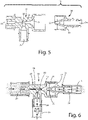
- the NAFC device 10 is illustrated in Figures 4-7 .
- the NAFC device 10 is a multiple-function, fluidic device with no moving parts.
- the NAFC device 10 includes an aerator 22 and a receiver 24.
- the receiver 24 is closely received and secured within the aerator 22.
- the aerator 22 includes a nutrient inlet (nutrient supply intake) 26 and an air inlet (air intake) 28 for receiving nutrient and air respectively.
- the aerator 22 further includes a nozzle 30 and a mixing chamber 38.
- the nozzle 24 includes a receiver port 32 and an outlet (grow tank supply outlet) 34.
- the receiver port 32 is aligned with the nozzle 30.
- the nutrient inlet 26 is connected to the manifold 108; the grow tank return hose (nutrient return line) 16 is connected to the air inlet 28; and the grow tank supply hose (nutrient supply line) 14 is connected to the output (grow tank supply outlet) 34.
- the air and the liquid mix; and oxygen is absorbed into the nutrient solution.
- Some of the air aspirated into the nutrient jet bypasses the receiver 32 and flows into the bypass chamber 41, through the bypass outlet 43, and into the reservoir 102. In this way, the NAFC devices 10 aerate the nutrient within the reservoir 102 as well as in the grow tanks 104.
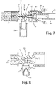
- Figure 7 illustrates the operation of the NAFC device 10 in a second mode when the nutrient level in the grow tank 104 rises above the end 18 of the grow tank return hose 16 within the grow tank 104.
- the nutrient liquid is then aspirated and drawn back through the grow tank return hose 16 and into the NAFC device 10 where it mixes with the nutrient jet in mixing chamber 38.
- This causes the nutrient jet to spread and contact the curved wall 40 that surrounds the nutrient jet.
- the nutrient jet is deflected by way of Coanda effect or wall attachment effect, and is diverted away from the receiver port 32. Flow to the grow tank is diminished or even stopped completely, so that the flow of liquid in the grow tank return hose 16 causes the grow tank level to drop back to the end 18 of the hose 16 at which point air is again aspirated and another cycle of filling is initiated.
- the NAFC device 10 cycles between the mode illustrated in Figure 6 and the mode illustrated in Figure 7 continue as long as the pump operates. This maintains the level in the grow tank at the end 18 of the grow tank return hose 16 and also circulates aerated nutrient.
- Complete turnover time for a given volume of grow tank nutrient can be controlled by the selection of the NAFC device nozzle diameter and the pump pressure. For example, an NAFC device 10 with a nozzle diameter of 2,082 mm (0.082 inches) and a pump pressure of 41,3685 kPa (6 psi) will cycle the nutrient solution in a 18,927061 (five-gallon) grow tank twice in one hour. Pumps may be run continuously or on a timer.
- Nutrient N enters the device through the intake port (nutrient supply intake) 26 and passes through the nozzle 30 to create the jet.
- the jet mixes with air received through the intake port (air intake) 28 and the aerated nutrient N' results.
- Figure 17 is a graph illustrating the nutrient flow and the airflow through the NAFC device 10 at various nutrient head pressures.
- the nutrient flow exceeds the airflow below a nutrient head pressure of approximately 3,048m (10 Ft). And the nutrient flow is less than the airflow above that nutrient head pressure.
- Anti-siphon means may be a small hole 42 in the side of the hose above the nutrient level as illustrated in Figure 11 .
- a check valve 44 may be placed in the intake port 28 to prevent the contents of the nutrient tank from siphoning into the grow tank if the grow tank nutrient level is below the nutrient reservoir level. If the grow tank nutrient level is above the nutrient reservoir level when the pump shuts off, the grow tank nutrient level will drop to the set point which is the vertical position of the end 18 of the hose 16 in the grow tank.
- the check valve 44 is preferably a duckbill type, but other check valves could be used. A low opening differential pressure is preferred so the aspiration of nutrient from the grow tank can occur at the fastest rate.
- Figures 9 and 10 illustrate the mounting of the hoses 14 and 16 on the grow tank 104.
- a bracket 20 attaches to the rim 46 of the grow tank 104 and directs the hoses downwardly into the grow tank.
- the supply hose 14 extends to a low level (as described above), and the end 19 preferably is positioned near the horizontal center of the grow tank 104, so that nutrient and air are introduced near the middle of the lower portion of the grow tank.
- the end 18 of the return hose 16 includes a filter 46 that prevents roots from entering the hose 16 and potentially blocking the hose.
- the filter 46 preferably is a porous plastic material. A porous plastic material is preferred over meshes or screens because roots can penetrate the openings in those types of filters.
- the return hose 16 may be slid within the bracket 20 so that the end 18 and the filter 46 may be placed at the desired nutrient solution level for the grow tank 104.
- the desired nutrient level may differ between plant pot sizes and may also change as the roots develop. In some cases, as the roots grow, the level will be set lower so that the root tips remain submerged while the root mass may be exposed to air to improve oxygen absorption.
- the return hose 16 is marked with a graduated scale indicating the depth of the nutrient liquid level. The system holds the liquid level accurately at the location of the end 18 of the return hose 16.
- Figure 10 illustrates a tubular filter or equalizer tube 46a, which may be used in place of the filter 46 illustrated in Figure 9 .
- the return hose 16 is located inside of the tubular filter 46a with its lower end 18 at the level set point.
- the inside diameter of the tubular filter 46a is larger than the outer diameter of the return hose 16.
- the porosity of the tubular filter 46a enables the liquid level inside the tubular filter to equalize with the grow tank level.
- the tubular filter 46a offers increased filter area for longer filter life.
- a Type II System is illustrated in Figure 2 and generally designated 200.
- the system 200 includes a nutrient reservoir 202 and a plurality of grow tanks 204.
- the nutrient solution within the nutrient reservoir 202 is distributed to the grow tanks 204 by way of a network of pressure pipes 210 and return pipes 212.
- the pressure and return pipes 210, 212 can be fitted with quick disconnects at each grow tank location so that each NAFC device 10 may be snapped into or removed from the pipes without interrupting the system operation.
- the reservoir 202 and the grow tanks 204 may be similar to, or different from, the reservoir 102 and the grow tanks 104 respectively.
- NAFC Nutrient Aerator and Flow Control
- Figures 12 and 13 illustrate the NAFC device 310 for a Type II hydroponic system.
- the NAFC device 310 includes an aerator 322 and a receiver 324.
- the aerator 322 is highly similar structurally and functionally to the aerator 22 previously described.
- the elements in the aerator 322 that correspond to elements in the aerator 22 are identified by the corresponding number preceded by the digit "3".
- the inlet port 326 corresponds to the inlet port (nutrient supply intake) 26, and so forth.
- the primary difference between the aerator 322 and the aerator 22 is that the inlet port 326 is threaded to receive a mating threaded component.
- the receiver 324 is highly similar functionally to the aerator 22 previously described.
- the elements in the receiver 324 that correspond to elements in the receiver 24 are identified by the corresponding number preceded by the digit "3". Accordingly, the receiver port 332 corresponds to the receiver port 32, and so forth.
- Two differences between the receiver 324 and the receiver 24 are that (a) the grow tank supply line port 334 extends transversely from the NAFC device 310 and (b) the outlet 335 includes an external fitting 337.
- Figure 14 illustrates the incorporation of the NAFC device 310 into the Type II system 200.
- the pressure line 210 is fitted with a tee 206 at each growing tank 204 along with a quick coupling 208 having a shut-off valve (not visible).
- the drain line 212 is fitted with a tee 214 along with a quick coupling having a shut-off valve (not visible). All of these components are fluidly and securely interconnected using techniques well known to those skilled in the art.
- the valves enable the NAFC unit 310 to be installed and removed without shutting off the pump. This enables modifications and service to be performed on individual growing stations without interrupting system operation.
- the drain line is always filled with nutrient solution at the reservoir head pressure.
- the check valves prevent the nutrient from leaking out when the NAFC device 310 is not installed.
- the NAFC device 310 is fitted with male quick-connect fittings.
- the NAFC grow tank connections are made first.
- the NAFC outlet is connected to the drain line.
- the NAFC inlet fitting is inserted into the quick coupler, which opens the shut-off valve, and operation begins.
- the quick coupling is first disconnected from the pressurized line, and then the NAFC device is disconnected from the drain coupling and the grow tank tubes.
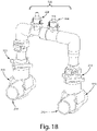
- Figure 18 illustrates an alternative embodiment to the arrangement illustrated in Figure 14 for connecting the NAFC device 310 in a Type II system 200.
- the figure 18 design incorporates pipe saddles 510 that may be attached to the nutrient supply line 210 and the nutrient drain line 212.
- the saddles 510 include sprinkler-system, snap-on, self-tapping tees 512 and 514 to connect the NAFC device 310 to the lines 210 and 212 respectively.
- the tees 512 and 514 simplify and reduce installation labor because the self-tapping tool is incorporated into the saddle 510.
- the saddles 510 can be added to an existing pipe run without draining the pipes.
- One suitable saddle is that made and sold by King Innovations for use in underground sprinkler systems.
- the NAFC has a mode of configuration and operation ideal for this situation.
- the NAFC device may operate as a high-efficiency, low-liquid-flow-rate aerator.
- an aerator 22 may be mounted to each grow tank and supplied by a central recirculation pump.
- the individual aerators 22 have a relatively low flow rate, so grow tank capacity will not be exceeded.
- the aerator 22 generates a high velocity liquid jet, which creates a strong aspiration of air into the jet. The strength of the aspiration effect is reflected by comparing the strength of the vacuum head created by the NAFC-A with other aerators at their normal operating flow rate.
- the aerator 22 operating at 3,048m (10 Ft.) of head develops a liquid flow rate of 14,761/h (0.65GPM or 39GPH). This is a manageable flow rate for a typical 22,712471 (6-gallon) grow tank drain system. This aerator produces a turnover rate of once every 6 minutes for a tank filled with 15,141651 (4 gallons) of nutrient.
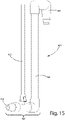
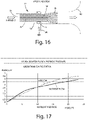
- FIG. 15 illustrates one embodiment of a grow tank aerator assembly 400 incorporating the NAFC-A aerator 422.
- the assembly 400 includes an aerator 422, an air supply pipe 402, a nutrient inlet port (nutrient supply intake) 426, a discharge tube 404, and a U 406. Nutrient is received through intake port 426, and the nutrient flows through the aerator 422 to be aerated as described above. The aerated nutrient solution is outputted into the tube 404 for discharge through the U 406 into the grow tank (not shown in Fig. 15 ).
- the U 406 enables the aerator assembly 400 to be mounted on the rim of a grow tank.
- the NAFC devices provide unique features to improve the performance of hydroponic nutrient circulation systems.
- the devices aerate the nutrient solution without the need for air pumps, air stones, and air tube plumbing.
- the devices circulate aerated nutrient solution without gravity drains or a common drain line connecting grow tanks and the nutrient reservoir.
- the devices provide individual grow tanks with adjustable level control without the need for mechanical or electrical valves.
- the devices can empty grow tanks without requiring drain holes in the grow tanks.
- the devices enable grow tanks to be mounted at individual elevations.
- the devices enable different size grow tanks to be serviced from the same nutrient reservoir.
- the devices when appropriately sized, provide rapid cycling (i.e. turnover) of grow tank nutrient solution.
- the devices may work with continuous or timed pump operation.
- the devices may be used with the most popular types of existing hydroponic systems.
- the devices enable an individual grow tank in a network to be serviced (i.e. moved, emptied, cleaned, replanted, etc.) without interrupting operation of the other tanks in the network.
- the aerator version (i.e. the NAFC-A device) delivers high aeration to individual grow tanks without exceeding the existing drain capacity of the systems.
Landscapes
- Life Sciences & Earth Sciences (AREA)
- Environmental Sciences (AREA)
- Engineering & Computer Science (AREA)
- Water Supply & Treatment (AREA)
- Hydroponics (AREA)
Claims (8)
- Un système de circulation de nutriments hydroponiques (100) comprenant :un réservoir de nutriments (102) ;une pluralité de réservoirs de culture (104) ;un système d'alimentation en nutriments pour fournir des nutriments du réservoir de nutriments (102) aux réservoirs de culture (104), le système d'alimentation en nutriments comprenant une ligne d'alimentation en nutriments (14) s'étendant dans chaque réservoir de culture (104) ;un système de retour de nutriments pour renvoyer les nutriments des réservoirs de culture (104) au réservoir de nutriments (102), le système de retour de nutriments comprenant une ligne de retour de nutriments (16) s'étendant dans chaque réservoir de culture (104) ; etune pluralité de dispositifs d'aération et de commande d'écoulement de nutriments, NAFC, (10), chaque dispositif NAFC (10) étant associé à la ligne d'alimentation en nutriments (14) d'un réservoir de culture respectif (104),chaque dispositif NAFC (10) comprenant :une entrée d'alimentation en nutriments (26) à laquelle le système d'alimentation en nutriments est connecté ;une entrée d'air (28) à laquelle la ligne de retour de nutriments associée (16) est connectée ;une buse (30) en communication fluidique avec l'entrée d'alimentation en nutriments (26) ;une chambre de mélange (38) en communication fluidique avec la buse (30) et avec l'entrée d'air (28) ;un orifice de réception (32) en communication fluidique avec la chambre de mélange (38) et aligné avec la buse (30) ;une chambre de dérivation (41) entourant l'orifice de réception (32), la chambre de dérivation (41) étant en communication fluidique avec la chambre de mélange (38) ; etune sortie d'alimentation de réservoir de culture (34) à laquelle la ligne d'alimentation en nutriments associée (14) est connectée, la sortie d'alimentation de réservoir de culture (34) étant en communication fluidique avec l'orifice de réception (32).
- Un système de circulation de nutriments hydroponiques (100) selon la revendication 1, dans lequel chaque ligne de retour de nutriments (16) a une extrémité inférieure (18) à un niveau de nutriments souhaité maintenu dans le réservoir de culture associé (104).
- Un système de circulation de nutriments hydroponiques (100) selon la revendication 2, dans lequel chaque ligne de retour de nutriments comprend une pince ou un support (20) adapté pour ajuster la position verticale de l'extrémité (18) dans le réservoir de culture associé (104).
- Un système de circulation de nutriments hydroponiques (100) selon l'une quelconque des revendications précédentes, dans lequel chaque dispositif NAFC (10) est associé à la ligne de retour de nutriments (16) de l'un des réservoirs de culture (104), et dans lequel chaque dispositif NAFC (10) fait partie d'un ensemble NAFC (12) qui comprend en outre sa ligne d'alimentation en nutriments associée (14) et sa ligne de retour de nutriments associée (16).
- Un système de circulation de nutriments hydroponiques (100) selon l'une quelconque des revendications 2 à 4, dans lequel, pour chaque dispositif NAFC (10), l'entrée d'air (28) :
reçoit de l'air pour le mélanger avec des nutriments provenant de l'entrée d'alimentation en nutriments (26) dans la chambre de mélange (38) lorsque les nutriments dans le réservoir de culture associé (104) sont en dessous de l'extrémité inférieure (18) de la ligne de retour de nutriments associée (16), de sorte qu'un jet de nutriments arrive sur l'orifice de réception (32) ; et reçoit des nutriments à mélanger avec des nutriments provenant de l'entrée d'alimentation en nutriments (26) dans la chambre de mélange (38) lorsque les nutriments dans le réservoir de culture associé (104) sont au-dessus de l'extrémité inférieure (18) de la ligne de retour de nutriments associée (16), de sorte que les nutriments sont détournés de l'orifice de réception (32). - Un système de circulation de nutriments hydroponiques (100) selon la revendication 1, dans lequel :le système d'alimentation en nutriments comprend une pompe (106) et un collecteur (108) dans le réservoir de nutriments (102), le collecteur (108) étant relié à la pompe (106) ;chaque dispositif NAFC (10) est relié au collecteur (108) ; et chaque chambre de dérivation (41) comprend une sortie (43) dans le réservoir (102).
- Un système de circulation de nutriments hydroponiques (100) selon l'une quelconque des revendications précédentes, dans lequel le dispositif NAFC (10) comprend en outre une pluralité de raccords rapides (208) pour connecter le dispositif NAFC (10) au système d'alimentation en nutriments et au système de retour de nutriments.
- Un système de circulation de nutriments hydroponiques comprenant :un réservoir de nutriments (102) ;une pluralité de réservoirs de culture (104) ;un système d'alimentation en nutriments pour fournir des nutriments du réservoir de nutriments (102) aux réservoirs de culture (104), le système d'alimentation en nutriments comprenant une ligne d'alimentation en nutriments (14) s'étendant dans chaque réservoir de culture (104) ;un système de retour de nutriments pour renvoyer les nutriments des réservoirs de culture (104) au réservoir de nutriments (102), le système de retour de nutriments comprenant une ligne de retour de nutriments (16) s'étendant dans chaque réservoir de culture (104) ; etune pluralité de dispositifs d'aération de nutriments (22), chaque dispositif (22) étant associé à la ligne d'alimentation en nutriments (14) d'un réservoir de culture respectif (104), chaque dispositif (22) comprenant :une entrée d'alimentation en nutriments (26) à laquelle le système d'alimentation en nutriments est connecté ;une entrée d'air (28) ;une buse (30) en communication fluidique avec l'entrée d'alimentation en nutriments (26) ; etune chambre de mélange (38) en communication fluidique avec la buse (30) et avec l'entrée d'air (28) et étant une sortie pour délivrer des nutriments directement dans le réservoir de culture respectif (104).
Applications Claiming Priority (2)
| Application Number | Priority Date | Filing Date | Title |
|---|---|---|---|
| US16/057,116 US10588276B2 (en) | 2018-08-07 | 2018-08-07 | Hydroponic nutrient aeration and flow control device and system |
| PCT/US2019/032138 WO2020033024A1 (fr) | 2018-08-07 | 2019-05-14 | Dispositif et système de commande de débit et d'aération d'éléments nutritifs hydroponiques |
Publications (3)
| Publication Number | Publication Date |
|---|---|
| EP3627986A1 EP3627986A1 (fr) | 2020-04-01 |
| EP3627986A4 EP3627986A4 (fr) | 2021-01-06 |
| EP3627986B1 true EP3627986B1 (fr) | 2022-05-11 |
Family
ID=69404924
Family Applications (1)
| Application Number | Title | Priority Date | Filing Date |
|---|---|---|---|
| EP19753232.8A Active EP3627986B1 (fr) | 2018-08-07 | 2019-05-14 | Dispositif de circulation pour solutions hydroponiques |
Country Status (5)
| Country | Link |
|---|---|
| US (2) | US10588276B2 (fr) |
| EP (1) | EP3627986B1 (fr) |
| JP (1) | JP6833063B2 (fr) |
| CN (1) | CN111010864B (fr) |
| WO (1) | WO2020033024A1 (fr) |
Families Citing this family (9)
| Publication number | Priority date | Publication date | Assignee | Title |
|---|---|---|---|---|
| WO2020163298A1 (fr) | 2019-02-05 | 2020-08-13 | Bard Access Systems, Inc. | Appareils et procédés pour moduler le profil de rigidité d'un stylet |
| WO2020252364A1 (fr) * | 2019-06-12 | 2020-12-17 | Noble Robert W | Système d'horticulture automatisé amélioré |
| US11219173B2 (en) * | 2020-04-17 | 2022-01-11 | Hydra Unlimited, Llc | Deep water culture hydroponic system |
| JP7493477B2 (ja) | 2021-03-22 | 2024-05-31 | 住友林業株式会社 | 緑化システム |
| US20230121664A1 (en) * | 2021-10-19 | 2023-04-20 | Hydra Unlimited, Llc | Large scale hydroponic system |
| US20230232759A1 (en) * | 2022-01-21 | 2023-07-27 | Christopher Farragut WATSON | Systems and method for automatic grow system |
| US12127515B1 (en) | 2023-04-25 | 2024-10-29 | Michael A. Sanzo | Hydroponic system for use in a desert-like environment |
| US20240365731A1 (en) * | 2023-05-04 | 2024-11-07 | Mason Sufnarski | Device, system, and method for hydroponic farming |
| US20240397890A1 (en) * | 2023-06-01 | 2024-12-05 | Battelle Memorial Institute | Electrochemical leaching for nutrient delivery in water |
Family Cites Families (47)
| Publication number | Priority date | Publication date | Assignee | Title |
|---|---|---|---|---|
| US1413107A (en) * | 1919-09-18 | 1922-04-18 | Petters Ltd | Carburetor |
| US1901806A (en) * | 1932-06-22 | 1933-03-14 | Fmc Corp | Atomizer |
| BE517287A (fr) * | 1952-02-05 | |||
| US3334657A (en) * | 1963-10-28 | 1967-08-08 | Smith | Adjustable fluid mixing devices |
| US3643376A (en) * | 1969-10-08 | 1972-02-22 | Everton G Poindexter | Production of seed sprouts |
| US3853271A (en) * | 1971-02-08 | 1974-12-10 | Woods Res & Dev Corp | Fluid discharge system |
| US3925926A (en) * | 1973-11-08 | 1975-12-16 | Kyowa Kagaku Kogyo Kk | Method and apparatus for water and air culture of plants |
| US4484601A (en) | 1982-08-02 | 1984-11-27 | Campau Daniel N | Liquid level control device |
| FR2536520B1 (fr) * | 1982-11-24 | 1986-04-18 | Agronomique Inst Nat Rech | Procede et dispositif de traitement thermique de fluide comportant une condensation rapide de vapeur |
| US4527593A (en) | 1983-05-04 | 1985-07-09 | Campau Daniel N | Apparatus and system for filling one or more containers with a liquid to a predetermined level |
| SU1319806A1 (ru) * | 1985-08-12 | 1987-06-30 | Мытищинский Совхоз Декоративного Садоводства Управления Лесопаркового Хозяйства Мосгорисполкома | Устройство дл гидропонного выращивани растений |
| JPH084731B2 (ja) * | 1985-10-11 | 1996-01-24 | 三菱レイヨン・エンジニアリング株式会社 | 気液混合装置 |
| JPS63100962A (ja) * | 1986-10-15 | 1988-05-06 | Ikeuchi:Kk | スプレ−ノズル |
| US4865776A (en) | 1988-05-19 | 1989-09-12 | Flow-Rite Controls, Ltd. | Apparatus for aerating water in a container |
| IL88105A0 (en) * | 1988-10-20 | 1989-06-30 | Shira Aeroponics 1984 Ltd | System for germination,propagation and growing plants in ultrasonic-fog conditions |
| IL95348A0 (en) * | 1990-08-12 | 1991-06-30 | Efim Fuks | Method of producing an increased hydrodynamic head of a fluid jet |
| US5876639A (en) | 1997-03-06 | 1999-03-02 | Flow-Rite Controls, Ltd. | Livewell and baitwell aerator |
| US8302884B1 (en) * | 2000-09-29 | 2012-11-06 | Novellus Systems, Inc. | Apparatus and method of effective fluid injection and vaporization for chemical vapor deposition application |
| EP1387610A1 (fr) | 2001-04-19 | 2004-02-11 | Clayton Boulter | Dispositif d'alimentation et refroidisseur hydroponique |
| US6682057B2 (en) * | 2001-05-01 | 2004-01-27 | Estr, Inc. | Aerator and wastewater treatment system |
| CA2364735C (fr) * | 2001-12-11 | 2009-11-03 | Jan A. Korzeniowski | Aspirateur-melangeur d'air |
| US7156377B2 (en) * | 2003-05-01 | 2007-01-02 | Chapman Teddie C | Water aeration device and method |
| US6986506B2 (en) * | 2003-05-01 | 2006-01-17 | Chapman Teddie C | Water aerator and method of using same |
| CN2682823Y (zh) * | 2004-02-20 | 2005-03-09 | 中国农业大学 | 高产深液流栽培装置 |
| US20060070675A1 (en) * | 2004-10-06 | 2006-04-06 | Maxwell Hsu | Pressurized gas-water mixer |
| TW200735767A (en) | 2005-11-30 | 2007-10-01 | Suntory Ltd | Vegetation planting unit and vegetation planting container |
| US20070152355A1 (en) * | 2005-12-30 | 2007-07-05 | Hartley John D | Cylindrical insert fluid injector / vacuum pump |
| JP2009044985A (ja) * | 2007-08-17 | 2009-03-05 | Globally Tech Kk | 水耕栽培システム |
| US8746965B2 (en) * | 2007-09-07 | 2014-06-10 | Turbulent Energy, Llc | Method of dynamic mixing of fluids |
| US20090293357A1 (en) | 2008-05-27 | 2009-12-03 | Ross Vickers | Aeroponic atomizer for horticulture |
| US7823328B2 (en) | 2009-02-27 | 2010-11-02 | Zack Allen Walhovd | Aeroponic plant growing system |
| CN201928766U (zh) * | 2011-01-10 | 2011-08-17 | 张焯柏 | 植物快繁系统 |
| DE102011017739A1 (de) * | 2011-04-28 | 2012-10-31 | Uwe Würdig | Verfahren und Vorrichtung zur Anreicherung einer Flüssigkeit mit Gas |
| GB201111082D0 (en) * | 2011-06-29 | 2011-08-10 | Univ Leeds | Bubble generation |
| US8621781B2 (en) * | 2011-09-27 | 2014-01-07 | Vijay Singh | Hydroponic irrigation system |
| JP5916350B2 (ja) * | 2011-11-16 | 2016-05-11 | 株式会社Icst | 高濃度酸素水生成装置、高濃度酸素水灌水装置および高濃度酸素水生成方法 |
| KR101264149B1 (ko) * | 2011-11-23 | 2013-05-14 | 주식회사 생명과기술 | 디퓨저 노즐 |
| US8667734B2 (en) * | 2012-03-28 | 2014-03-11 | Dan Johnson | Hydroponic plant container with highly oxygenated nutrient solution using continuous air injection and continuous coriolis effect mixing |
| US20140075841A1 (en) * | 2012-09-19 | 2014-03-20 | Brad Degraff | Hydroponic growing system |
| KR101240375B1 (ko) * | 2012-10-26 | 2013-03-07 | (주)우성하이텍 | 식물재배장치 |
| MX2015014019A (es) | 2013-04-03 | 2016-07-05 | Mitsui Chemicals Inc | Sistema de cultivo vegetal, metodo de cultivo vegetal usando el sistema de cultivo vegetal y metodo de produccion para el sistema de cultivo vegetal. |
| US10321696B2 (en) * | 2013-05-30 | 2019-06-18 | Haier Group Corporation | Vegetable preservation and growing case and vegetable preservation method |
| US20150289463A1 (en) * | 2014-04-09 | 2015-10-15 | David Moriarty | Hydroponic grow system |
| CA2892131C (fr) * | 2015-05-25 | 2025-08-05 | Michael C. WATSON | Systeme de croissance vegetale brumiponique |
| US20170020095A1 (en) * | 2015-07-23 | 2017-01-26 | Stephen Donald Kamholz | Plant growing apparatus, systems and methods |
| US10492385B2 (en) * | 2015-10-01 | 2019-12-03 | Tyler West | Highly efficient plant irrigation device and method for using the same |
| US20170208757A1 (en) * | 2016-01-22 | 2017-07-27 | Justin Jean Leonard VALMONT | Horticultural nutrient control system and method for using same |
-
2018
- 2018-08-07 US US16/057,116 patent/US10588276B2/en active Active
-
2019
- 2019-05-14 JP JP2019555947A patent/JP6833063B2/ja active Active
- 2019-05-14 CN CN201980002322.0A patent/CN111010864B/zh active Active
- 2019-05-14 EP EP19753232.8A patent/EP3627986B1/fr active Active
- 2019-05-14 WO PCT/US2019/032138 patent/WO2020033024A1/fr not_active Ceased
-
2020
- 2020-01-31 US US16/778,507 patent/US20200163298A1/en not_active Abandoned
Also Published As
| Publication number | Publication date |
|---|---|
| US20200163298A1 (en) | 2020-05-28 |
| US10588276B2 (en) | 2020-03-17 |
| WO2020033024A1 (fr) | 2020-02-13 |
| CN111010864B (zh) | 2021-09-14 |
| EP3627986A1 (fr) | 2020-04-01 |
| CN111010864A (zh) | 2020-04-14 |
| JP6833063B2 (ja) | 2021-02-24 |
| JP2020528732A (ja) | 2020-10-01 |
| EP3627986A4 (fr) | 2021-01-06 |
| US20200045899A1 (en) | 2020-02-13 |
Similar Documents
| Publication | Publication Date | Title |
|---|---|---|
| EP3627986B1 (fr) | Dispositif de circulation pour solutions hydroponiques | |
| DK167947B1 (da) | Vandingsventil til dyrkningsbord samt vandingsanlaeg hermed | |
| CA3169558C (fr) | Systeme hydroponique de culture a eau profonde | |
| AU2019219870C1 (en) | Hydroponic nutrient aeration and flow control device and system | |
| CA3231823A1 (fr) | Systeme hydroponique a grande echelle | |
| US20200229362A1 (en) | Recirculating Aeroponics System for Plant Growing | |
| US20210185952A1 (en) | Hydroponic nutrient solution aeration device | |
| US20060218860A1 (en) | System 4000 - Hydroponics System | |
| HK40028191A (en) | Hydroponic nutrient aeration and flow control device and system | |
| HK40028191B (en) | Hydroponic nutrient aeration and flow control device and system | |
| CN213427581U (zh) | 一种新型植物培育营养液补给系统及植物栽培箱 | |
| CN219228404U (zh) | 管道灌溉系统 | |
| KR200236771Y1 (ko) | 공기유입 차단수단이 구비된 양액자동 공급장치 | |
| CN223786794U (zh) | 一种果园滴灌装置和种植系统 | |
| HK40075982A (en) | Deep water culture hydroponic system | |
| CN112772095A (zh) | 一种用于植物栽培的水肥一体化滴灌系统 |
Legal Events
| Date | Code | Title | Description |
|---|---|---|---|
| STAA | Information on the status of an ep patent application or granted ep patent |
Free format text: STATUS: UNKNOWN |
|
| STAA | Information on the status of an ep patent application or granted ep patent |
Free format text: STATUS: THE INTERNATIONAL PUBLICATION HAS BEEN MADE |
|
| PUAI | Public reference made under article 153(3) epc to a published international application that has entered the european phase |
Free format text: ORIGINAL CODE: 0009012 |
|
| STAA | Information on the status of an ep patent application or granted ep patent |
Free format text: STATUS: REQUEST FOR EXAMINATION WAS MADE |
|
| 17P | Request for examination filed |
Effective date: 20190823 |
|
| AK | Designated contracting states |
Kind code of ref document: A1 Designated state(s): AL AT BE BG CH CY CZ DE DK EE ES FI FR GB GR HR HU IE IS IT LI LT LU LV MC MK MT NL NO PL PT RO RS SE SI SK SM TR |
|
| AX | Request for extension of the european patent |
Extension state: BA ME |
|
| RAP1 | Party data changed (applicant data changed or rights of an application transferred) |
Owner name: HYDRA UNLIMITED, LLC |
|
| REG | Reference to a national code |
Ref country code: DE Ref legal event code: R079 Ref document number: 602019014933 Country of ref document: DE Free format text: PREVIOUS MAIN CLASS: A01G0025160000 Ipc: A01G0031020000 |
|
| A4 | Supplementary search report drawn up and despatched |
Effective date: 20201209 |
|
| RIC1 | Information provided on ipc code assigned before grant |
Ipc: A01G 31/02 20060101AFI20201203BHEP Ipc: A01G 27/00 20060101ALI20201203BHEP |
|
| RIN1 | Information on inventor provided before grant (corrected) |
Inventor name: HERREMA, MARK W. Inventor name: CAMPAU, DANIEL N |
|
| STAA | Information on the status of an ep patent application or granted ep patent |
Free format text: STATUS: EXAMINATION IS IN PROGRESS |
|
| 17Q | First examination report despatched |
Effective date: 20210610 |
|
| DAV | Request for validation of the european patent (deleted) | ||
| DAX | Request for extension of the european patent (deleted) | ||
| GRAP | Despatch of communication of intention to grant a patent |
Free format text: ORIGINAL CODE: EPIDOSNIGR1 |
|
| STAA | Information on the status of an ep patent application or granted ep patent |
Free format text: STATUS: GRANT OF PATENT IS INTENDED |
|
| INTG | Intention to grant announced |
Effective date: 20220105 |
|
| GRAS | Grant fee paid |
Free format text: ORIGINAL CODE: EPIDOSNIGR3 |
|
| GRAA | (expected) grant |
Free format text: ORIGINAL CODE: 0009210 |
|
| STAA | Information on the status of an ep patent application or granted ep patent |
Free format text: STATUS: THE PATENT HAS BEEN GRANTED |
|
| AK | Designated contracting states |
Kind code of ref document: B1 Designated state(s): AL AT BE BG CH CY CZ DE DK EE ES FI FR GB GR HR HU IE IS IT LI LT LU LV MC MK MT NL NO PL PT RO RS SE SI SK SM TR |
|
| REG | Reference to a national code |
Ref country code: GB Ref legal event code: FG4D |
|
| REG | Reference to a national code |
Ref country code: CH Ref legal event code: EP |
|
| REG | Reference to a national code |
Ref country code: AT Ref legal event code: REF Ref document number: 1490609 Country of ref document: AT Kind code of ref document: T Effective date: 20220515 |
|
| REG | Reference to a national code |
Ref country code: DE Ref legal event code: R096 Ref document number: 602019014933 Country of ref document: DE |
|
| REG | Reference to a national code |
Ref country code: IE Ref legal event code: FG4D |
|
| REG | Reference to a national code |
Ref country code: NL Ref legal event code: FP |
|
| REG | Reference to a national code |
Ref country code: LT Ref legal event code: MG9D |
|
| REG | Reference to a national code |
Ref country code: AT Ref legal event code: MK05 Ref document number: 1490609 Country of ref document: AT Kind code of ref document: T Effective date: 20220511 |
|
| PG25 | Lapsed in a contracting state [announced via postgrant information from national office to epo] |
Ref country code: SE Free format text: LAPSE BECAUSE OF FAILURE TO SUBMIT A TRANSLATION OF THE DESCRIPTION OR TO PAY THE FEE WITHIN THE PRESCRIBED TIME-LIMIT Effective date: 20220511 Ref country code: PT Free format text: LAPSE BECAUSE OF FAILURE TO SUBMIT A TRANSLATION OF THE DESCRIPTION OR TO PAY THE FEE WITHIN THE PRESCRIBED TIME-LIMIT Effective date: 20220912 Ref country code: NO Free format text: LAPSE BECAUSE OF FAILURE TO SUBMIT A TRANSLATION OF THE DESCRIPTION OR TO PAY THE FEE WITHIN THE PRESCRIBED TIME-LIMIT Effective date: 20220811 Ref country code: LT Free format text: LAPSE BECAUSE OF FAILURE TO SUBMIT A TRANSLATION OF THE DESCRIPTION OR TO PAY THE FEE WITHIN THE PRESCRIBED TIME-LIMIT Effective date: 20220511 Ref country code: HR Free format text: LAPSE BECAUSE OF FAILURE TO SUBMIT A TRANSLATION OF THE DESCRIPTION OR TO PAY THE FEE WITHIN THE PRESCRIBED TIME-LIMIT Effective date: 20220511 Ref country code: GR Free format text: LAPSE BECAUSE OF FAILURE TO SUBMIT A TRANSLATION OF THE DESCRIPTION OR TO PAY THE FEE WITHIN THE PRESCRIBED TIME-LIMIT Effective date: 20220812 Ref country code: FI Free format text: LAPSE BECAUSE OF FAILURE TO SUBMIT A TRANSLATION OF THE DESCRIPTION OR TO PAY THE FEE WITHIN THE PRESCRIBED TIME-LIMIT Effective date: 20220511 Ref country code: ES Free format text: LAPSE BECAUSE OF FAILURE TO SUBMIT A TRANSLATION OF THE DESCRIPTION OR TO PAY THE FEE WITHIN THE PRESCRIBED TIME-LIMIT Effective date: 20220511 Ref country code: BG Free format text: LAPSE BECAUSE OF FAILURE TO SUBMIT A TRANSLATION OF THE DESCRIPTION OR TO PAY THE FEE WITHIN THE PRESCRIBED TIME-LIMIT Effective date: 20220811 Ref country code: AT Free format text: LAPSE BECAUSE OF FAILURE TO SUBMIT A TRANSLATION OF THE DESCRIPTION OR TO PAY THE FEE WITHIN THE PRESCRIBED TIME-LIMIT Effective date: 20220511 |
|
| PG25 | Lapsed in a contracting state [announced via postgrant information from national office to epo] |
Ref country code: RS Free format text: LAPSE BECAUSE OF FAILURE TO SUBMIT A TRANSLATION OF THE DESCRIPTION OR TO PAY THE FEE WITHIN THE PRESCRIBED TIME-LIMIT Effective date: 20220511 Ref country code: PL Free format text: LAPSE BECAUSE OF FAILURE TO SUBMIT A TRANSLATION OF THE DESCRIPTION OR TO PAY THE FEE WITHIN THE PRESCRIBED TIME-LIMIT Effective date: 20220511 Ref country code: LV Free format text: LAPSE BECAUSE OF FAILURE TO SUBMIT A TRANSLATION OF THE DESCRIPTION OR TO PAY THE FEE WITHIN THE PRESCRIBED TIME-LIMIT Effective date: 20220511 Ref country code: IS Free format text: LAPSE BECAUSE OF FAILURE TO SUBMIT A TRANSLATION OF THE DESCRIPTION OR TO PAY THE FEE WITHIN THE PRESCRIBED TIME-LIMIT Effective date: 20220911 |
|
| REG | Reference to a national code |
Ref country code: CH Ref legal event code: PL |
|
| REG | Reference to a national code |
Ref country code: BE Ref legal event code: MM Effective date: 20220531 |
|
| PG25 | Lapsed in a contracting state [announced via postgrant information from national office to epo] |
Ref country code: SM Free format text: LAPSE BECAUSE OF FAILURE TO SUBMIT A TRANSLATION OF THE DESCRIPTION OR TO PAY THE FEE WITHIN THE PRESCRIBED TIME-LIMIT Effective date: 20220511 Ref country code: SK Free format text: LAPSE BECAUSE OF FAILURE TO SUBMIT A TRANSLATION OF THE DESCRIPTION OR TO PAY THE FEE WITHIN THE PRESCRIBED TIME-LIMIT Effective date: 20220511 Ref country code: RO Free format text: LAPSE BECAUSE OF FAILURE TO SUBMIT A TRANSLATION OF THE DESCRIPTION OR TO PAY THE FEE WITHIN THE PRESCRIBED TIME-LIMIT Effective date: 20220511 Ref country code: LU Free format text: LAPSE BECAUSE OF NON-PAYMENT OF DUE FEES Effective date: 20220514 Ref country code: LI Free format text: LAPSE BECAUSE OF NON-PAYMENT OF DUE FEES Effective date: 20220531 Ref country code: EE Free format text: LAPSE BECAUSE OF FAILURE TO SUBMIT A TRANSLATION OF THE DESCRIPTION OR TO PAY THE FEE WITHIN THE PRESCRIBED TIME-LIMIT Effective date: 20220511 Ref country code: DK Free format text: LAPSE BECAUSE OF FAILURE TO SUBMIT A TRANSLATION OF THE DESCRIPTION OR TO PAY THE FEE WITHIN THE PRESCRIBED TIME-LIMIT Effective date: 20220511 Ref country code: CZ Free format text: LAPSE BECAUSE OF FAILURE TO SUBMIT A TRANSLATION OF THE DESCRIPTION OR TO PAY THE FEE WITHIN THE PRESCRIBED TIME-LIMIT Effective date: 20220511 Ref country code: CH Free format text: LAPSE BECAUSE OF NON-PAYMENT OF DUE FEES Effective date: 20220531 |
|
| REG | Reference to a national code |
Ref country code: DE Ref legal event code: R097 Ref document number: 602019014933 Country of ref document: DE |
|
| PG25 | Lapsed in a contracting state [announced via postgrant information from national office to epo] |
Ref country code: MC Free format text: LAPSE BECAUSE OF FAILURE TO SUBMIT A TRANSLATION OF THE DESCRIPTION OR TO PAY THE FEE WITHIN THE PRESCRIBED TIME-LIMIT Effective date: 20220511 |
|
| PLBE | No opposition filed within time limit |
Free format text: ORIGINAL CODE: 0009261 |
|
| STAA | Information on the status of an ep patent application or granted ep patent |
Free format text: STATUS: NO OPPOSITION FILED WITHIN TIME LIMIT |
|
| PG25 | Lapsed in a contracting state [announced via postgrant information from national office to epo] |
Ref country code: AL Free format text: LAPSE BECAUSE OF FAILURE TO SUBMIT A TRANSLATION OF THE DESCRIPTION OR TO PAY THE FEE WITHIN THE PRESCRIBED TIME-LIMIT Effective date: 20220511 |
|
| 26N | No opposition filed |
Effective date: 20230214 |
|
| PG25 | Lapsed in a contracting state [announced via postgrant information from national office to epo] |
Ref country code: IE Free format text: LAPSE BECAUSE OF NON-PAYMENT OF DUE FEES Effective date: 20220514 |
|
| PG25 | Lapsed in a contracting state [announced via postgrant information from national office to epo] |
Ref country code: SI Free format text: LAPSE BECAUSE OF FAILURE TO SUBMIT A TRANSLATION OF THE DESCRIPTION OR TO PAY THE FEE WITHIN THE PRESCRIBED TIME-LIMIT Effective date: 20220511 Ref country code: BE Free format text: LAPSE BECAUSE OF NON-PAYMENT OF DUE FEES Effective date: 20220531 |
|
| P01 | Opt-out of the competence of the unified patent court (upc) registered |
Effective date: 20230522 |
|
| PG25 | Lapsed in a contracting state [announced via postgrant information from national office to epo] |
Ref country code: MK Free format text: LAPSE BECAUSE OF FAILURE TO SUBMIT A TRANSLATION OF THE DESCRIPTION OR TO PAY THE FEE WITHIN THE PRESCRIBED TIME-LIMIT Effective date: 20220511 Ref country code: CY Free format text: LAPSE BECAUSE OF FAILURE TO SUBMIT A TRANSLATION OF THE DESCRIPTION OR TO PAY THE FEE WITHIN THE PRESCRIBED TIME-LIMIT Effective date: 20220511 |
|
| PG25 | Lapsed in a contracting state [announced via postgrant information from national office to epo] |
Ref country code: HU Free format text: LAPSE BECAUSE OF FAILURE TO SUBMIT A TRANSLATION OF THE DESCRIPTION OR TO PAY THE FEE WITHIN THE PRESCRIBED TIME-LIMIT; INVALID AB INITIO Effective date: 20190514 |
|
| PG25 | Lapsed in a contracting state [announced via postgrant information from national office to epo] |
Ref country code: MT Free format text: LAPSE BECAUSE OF FAILURE TO SUBMIT A TRANSLATION OF THE DESCRIPTION OR TO PAY THE FEE WITHIN THE PRESCRIBED TIME-LIMIT Effective date: 20220511 |
|
| PG25 | Lapsed in a contracting state [announced via postgrant information from national office to epo] |
Ref country code: BG Free format text: LAPSE BECAUSE OF FAILURE TO SUBMIT A TRANSLATION OF THE DESCRIPTION OR TO PAY THE FEE WITHIN THE PRESCRIBED TIME-LIMIT Effective date: 20220511 |
|
| PG25 | Lapsed in a contracting state [announced via postgrant information from national office to epo] |
Ref country code: BG Free format text: LAPSE BECAUSE OF FAILURE TO SUBMIT A TRANSLATION OF THE DESCRIPTION OR TO PAY THE FEE WITHIN THE PRESCRIBED TIME-LIMIT Effective date: 20220511 |
|
| PGFP | Annual fee paid to national office [announced via postgrant information from national office to epo] |
Ref country code: NL Payment date: 20250317 Year of fee payment: 7 |
|
| PGFP | Annual fee paid to national office [announced via postgrant information from national office to epo] |
Ref country code: FR Payment date: 20250310 Year of fee payment: 7 |
|
| PGFP | Annual fee paid to national office [announced via postgrant information from national office to epo] |
Ref country code: GB Payment date: 20250320 Year of fee payment: 7 |
|
| PGFP | Annual fee paid to national office [announced via postgrant information from national office to epo] |
Ref country code: DE Payment date: 20250319 Year of fee payment: 7 |
|
| PGFP | Annual fee paid to national office [announced via postgrant information from national office to epo] |
Ref country code: IT Payment date: 20250422 Year of fee payment: 7 |
|
| PG25 | Lapsed in a contracting state [announced via postgrant information from national office to epo] |
Ref country code: TR Free format text: LAPSE BECAUSE OF FAILURE TO SUBMIT A TRANSLATION OF THE DESCRIPTION OR TO PAY THE FEE WITHIN THE PRESCRIBED TIME-LIMIT Effective date: 20220511 |