EP3628021B1 - Ensemble réservoir de filtre à lamelles - Google Patents
Ensemble réservoir de filtre à lamelles Download PDFInfo
- Publication number
- EP3628021B1 EP3628021B1 EP19794872.2A EP19794872A EP3628021B1 EP 3628021 B1 EP3628021 B1 EP 3628021B1 EP 19794872 A EP19794872 A EP 19794872A EP 3628021 B1 EP3628021 B1 EP 3628021B1
- Authority
- EP
- European Patent Office
- Prior art keywords
- compartment
- tank assembly
- liquid
- drain
- pollutants
- Prior art date
- Legal status (The legal status is an assumption and is not a legal conclusion. Google has not performed a legal analysis and makes no representation as to the accuracy of the status listed.)
- Active
Links
Images


Classifications
-
- C—CHEMISTRY; METALLURGY
- C02—TREATMENT OF WATER, WASTE WATER, SEWAGE, OR SLUDGE
- C02F—TREATMENT OF WATER, WASTE WATER, SEWAGE, OR SLUDGE
- C02F1/00—Treatment of water, waste water, or sewage
- C02F1/001—Processes for the treatment of water whereby the filtration technique is of importance
- C02F1/004—Processes for the treatment of water whereby the filtration technique is of importance using large scale industrial sized filters
-
- C—CHEMISTRY; METALLURGY
- C02—TREATMENT OF WATER, WASTE WATER, SEWAGE, OR SLUDGE
- C02F—TREATMENT OF WATER, WASTE WATER, SEWAGE, OR SLUDGE
- C02F9/00—Multistage treatment of water, waste water or sewage
-
- B—PERFORMING OPERATIONS; TRANSPORTING
- B01—PHYSICAL OR CHEMICAL PROCESSES OR APPARATUS IN GENERAL
- B01D—SEPARATION
- B01D17/00—Separation of liquids, not provided for elsewhere, e.g. by thermal diffusion
- B01D17/02—Separation of non-miscible liquids
- B01D17/0208—Separation of non-miscible liquids by sedimentation
- B01D17/0214—Separation of non-miscible liquids by sedimentation with removal of one of the phases
-
- B—PERFORMING OPERATIONS; TRANSPORTING
- B01—PHYSICAL OR CHEMICAL PROCESSES OR APPARATUS IN GENERAL
- B01D—SEPARATION
- B01D21/00—Separation of suspended solid particles from liquids by sedimentation
- B01D21/0024—Inlets or outlets provided with regulating devices, e.g. valves, flaps
-
- B—PERFORMING OPERATIONS; TRANSPORTING
- B01—PHYSICAL OR CHEMICAL PROCESSES OR APPARATUS IN GENERAL
- B01D—SEPARATION
- B01D21/00—Separation of suspended solid particles from liquids by sedimentation
- B01D21/0039—Settling tanks provided with contact surfaces, e.g. baffles, particles
- B01D21/0045—Plurality of essentially parallel plates
-
- B—PERFORMING OPERATIONS; TRANSPORTING
- B01—PHYSICAL OR CHEMICAL PROCESSES OR APPARATUS IN GENERAL
- B01D—SEPARATION
- B01D21/00—Separation of suspended solid particles from liquids by sedimentation
- B01D21/0087—Settling tanks provided with means for ensuring a special flow pattern, e.g. even inflow or outflow
-
- B—PERFORMING OPERATIONS; TRANSPORTING
- B01—PHYSICAL OR CHEMICAL PROCESSES OR APPARATUS IN GENERAL
- B01D—SEPARATION
- B01D21/00—Separation of suspended solid particles from liquids by sedimentation
- B01D21/24—Feed or discharge mechanisms for settling tanks
- B01D21/2405—Feed mechanisms for settling tanks
- B01D21/2416—Liquid distributors with a plurality of feed points
-
- B—PERFORMING OPERATIONS; TRANSPORTING
- B01—PHYSICAL OR CHEMICAL PROCESSES OR APPARATUS IN GENERAL
- B01D—SEPARATION
- B01D21/00—Separation of suspended solid particles from liquids by sedimentation
- B01D21/24—Feed or discharge mechanisms for settling tanks
- B01D21/2427—The feed or discharge opening located at a distant position from the side walls
-
- B—PERFORMING OPERATIONS; TRANSPORTING
- B01—PHYSICAL OR CHEMICAL PROCESSES OR APPARATUS IN GENERAL
- B01D—SEPARATION
- B01D21/00—Separation of suspended solid particles from liquids by sedimentation
- B01D21/24—Feed or discharge mechanisms for settling tanks
- B01D21/2433—Discharge mechanisms for floating particles
-
- B—PERFORMING OPERATIONS; TRANSPORTING
- B01—PHYSICAL OR CHEMICAL PROCESSES OR APPARATUS IN GENERAL
- B01D—SEPARATION
- B01D21/00—Separation of suspended solid particles from liquids by sedimentation
- B01D21/24—Feed or discharge mechanisms for settling tanks
- B01D21/245—Discharge mechanisms for the sediments
- B01D21/2472—Means for fluidising the sediments, e.g. by jets or mechanical agitators
-
- C—CHEMISTRY; METALLURGY
- C02—TREATMENT OF WATER, WASTE WATER, SEWAGE, OR SLUDGE
- C02F—TREATMENT OF WATER, WASTE WATER, SEWAGE, OR SLUDGE
- C02F1/00—Treatment of water, waste water, or sewage
- C02F1/001—Processes for the treatment of water whereby the filtration technique is of importance
-
- C—CHEMISTRY; METALLURGY
- C02—TREATMENT OF WATER, WASTE WATER, SEWAGE, OR SLUDGE
- C02F—TREATMENT OF WATER, WASTE WATER, SEWAGE, OR SLUDGE
- C02F1/00—Treatment of water, waste water, or sewage
- C02F1/40—Devices for separating or removing fatty or oily substances or similar floating material
-
- C—CHEMISTRY; METALLURGY
- C02—TREATMENT OF WATER, WASTE WATER, SEWAGE, OR SLUDGE
- C02F—TREATMENT OF WATER, WASTE WATER, SEWAGE, OR SLUDGE
- C02F1/00—Treatment of water, waste water, or sewage
- C02F2001/007—Processes including a sedimentation step
-
- C—CHEMISTRY; METALLURGY
- C02—TREATMENT OF WATER, WASTE WATER, SEWAGE, OR SLUDGE
- C02F—TREATMENT OF WATER, WASTE WATER, SEWAGE, OR SLUDGE
- C02F2201/00—Apparatus for treatment of water, waste water or sewage
- C02F2201/002—Construction details of the apparatus
- C02F2201/004—Seals, connections
-
- Y—GENERAL TAGGING OF NEW TECHNOLOGICAL DEVELOPMENTS; GENERAL TAGGING OF CROSS-SECTIONAL TECHNOLOGIES SPANNING OVER SEVERAL SECTIONS OF THE IPC; TECHNICAL SUBJECTS COVERED BY FORMER USPC CROSS-REFERENCE ART COLLECTIONS [XRACs] AND DIGESTS
- Y02—TECHNOLOGIES OR APPLICATIONS FOR MITIGATION OR ADAPTATION AGAINST CLIMATE CHANGE
- Y02A—TECHNOLOGIES FOR ADAPTATION TO CLIMATE CHANGE
- Y02A20/00—Water conservation; Efficient water supply; Efficient water use
- Y02A20/152—Water filtration
Definitions
- the present invention relates generally to lamella filters, and more particularly to a lamella filter tank assembly.
- a tank assembly for the treatment of waste streams that include settling pollutants and floating pollutants.
- the tank assembly includes an inlet conduit, a first compartment that includes a first drain at a bottom thereof, a second compartment that includes a second drain at a bottom thereof, a third compartment that includes a third drain at a bottom thereof, and an outlet conduit.
- the second compartment also includes at least a first lamella filter package disposed therein.
- the third compartment also includes a skimmer, an underrun member and an overrun member.
- a liquid flow path is defined from the inlet conduit, through the first compartment, through the second compartment and the first lamella filter pack, through the third compartment, past the skimmer, under the underrun, over the overrun and out the outlet conduit.
- the first compartment includes a flowbreaker that is positioned at the end of the inlet conduit in the first compartment.
- the inlet conduit divides into first and second sections, the flowbreaker is positioned at an end of the first section, and a second flowbreaker is positioned at an end of the second section.
- the overrun has an upper edge that defines a first height
- the underrun defines a lower edge that defines second height
- the first height is higher than the second height
- the tank assembly includes a sludge removal conduit that is in fluid communication with the first, second and third drains.
- the first compartment includes a first lower cone section that includes the first drain therein
- the second compartment includes a second lower cone section that includes the second drain therein
- the third compartment includes a third lower cone section that includes the third drain therein.
- the tank assembly includes a cleaning system that includes a first line that inputs liquid into the first cone and/or first drain, a second line that inputs liquid into the second cone and/or second drain, and a third line that inputs liquid into the third cone and/or third drain.
- the second compartment includes a plurality of lamella filter packs positioned in series within the liquid flow path. It will be appreciated that a floating pollutants path is defined from the inlet conduit, through the first compartment, through the second compartment and the first lamella filter pack, into the third compartment and into the skimmer.
- a method of treating a waste stream that includes liquid, settling pollutants and floating pollutants in a tank assembly includes flowing the liquid into an inlet conduit, flowing the liquid through a first compartment that includes a first drain at a bottom thereof, where a first portion of settling pollutants settle to the first drain, flowing the liquid into a second compartment and through a first lamella filter package disposed therein, where a second portion of settling pollutants settle to a second drain at a bottom of the second compartment, and flowing the liquid into a third compartment that includes a third drain at a bottom thereof.
- the third compartment also includes a skimmer, an underrun member and an overrun member. A third portion of settling pollutants settle to the third drain and the floating pollutants are removed by the skimmer.
- the method also includes flowing the liquid under the underrun, flowing the liquid over the overrun, and flowing the liquid through the outlet conduit.
- the present invention includes a lamella filter tank, assembly and system.
- the system is mobile.
- the present invention combines the removal of floating pollution and the removal of settling pollution into one system and includes multiple and different connections for removal of oil and removal of settling pollutants.
- the tank includes three separate separation compartments. Water or other liquid enters the first compartment from a pipe at one end and the liquid flows through the pipe to the top where a flowbreaker is positioned. In the flowbreaker and the first compartment, the water is divided over the total width of the system to reduce the flow speed or velocity of the water, which causes particles to start settling out or start floating.
- the flowbreaker is specifically designed to minimize the risk of blockages.
- the particles enter the second compartment where the vertical lamella packages are located.
- the flow is divided over a plurality of parallel channels. Each channel only receives a small amount of the flow of the liquid.
- the turbulence of the water in each channel is at or close to zero between each of the plates in each channel. Because the turbulence is at or close to zero, the small pollutants start settling or floating.
- the lamella filters create a zone with very little or no turbulence, and, because the particles start to cling or bind together, they start to settle toward the bottom. Therefore, in the lamella packs, the turbulence is reduced and the binding capabilities of particles are stimulated or increased.
- This compartment preferably includes an underrun and an overrun that is directing the desired flow pattern or flow path in the lamella filter tank so when oil particles are floating there is no flow going over the top of the tank because then the removed oily pollution will be removed toward the effluent side of the tank. This is why the underrun is provided. And, the overrun is provided to maintain the right level and the constant level in the tank.
- the particles After settling of particles takes place in each section of the tank, the particles end up in the cone under each compartment.
- the user can choose, based on taking samples, which sludge they want to pump from the system to a sludge dewatering system or recycling system. Therefore, if the user wants to reuse any of the sludges (from any of the cones), the user can open one of the cones separately and send specifically that sludge to a desired process.
- a floating skimmer is optionally included in the second compartment.
- the skimmer allows the user to separately transport the removed oil to a different process.
- the four hatches on top of the roof make it possible to clean the complete system from the top. With these hatches there is no corner which cannot be reached with a mobile high pressure cleaner.
- the inventive tank assembly disclosed herein is preferably mobile, includes vertical lamella packages in a mobile system, has three or four flush sludge removal systems at the bottom of each hopper or cone by which known operational issues of auger systems are avoided, removes settling and floating pollution at the same time, includes a skimmer in front of the underrun, separates different sludges within each compartment, and is a fully closed system.
- the tank assembly can be used with the dewatering box taught in U.S. Patent App. No. _ (Atty Docket No. 78162-5033).
- the sludge that is removed from the bottom of the compartments can be pumped into or otherwise inserted into the dewatering box so that the sludge can be further dewatered.
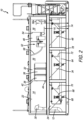
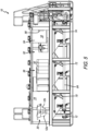
- FIGS. 1-6 show a lamella filter tank assembly 10 that is used for the treatment of waste streams that include settling pollutants and/or floating pollutants.
- the tank assembly 10 includes a tank 11 that includes an inlet conduit 12, a first compartment 14, a second compartment 16, a third compartment 18 and an outlet conduit 20.
- the first compartment 14 includes a first upper section 22, a first lower cone section 24 and a first drain 26 at the bottom of the first compartment.
- the inlet conduit 12 communicates the interior of the tank 11 with the exterior, e.g., by a flange connection 28 or the like.
- the inlet conduit 12 includes a flowbreaker 30, on the end thereof, which breaks the flow of the entering liquid and begins to slow it down and decrease turbulence. As shown in FIG. 4 , the inlet conduit 12 divides into first and second sections 12a and 12b and a flowbreaker 30 is positioned at the end of both sections.
- the second compartment 16 includes a second upper section 32, a second lower cone section 34 and a second drain 36 at the bottom of the second compartment 16.
- the second compartment 16 includes at least one and preferably a plurality of lamella filter packages 38 disposed therein.
- each lamella filter package 38 preferably include a plurality of parallel plates 40 therein that define space therebetween for liquid to flow through.
- the plates 40 are arranged in a vertical arrangement.
- the plates 40 have a wave form shape, as shown in FIG. 4 .
- this is not a limitation on the present invention and other shapes or arrangements, such as flat, zig-zag, etc., are within the scope of the invention.
- the wave shape provides areas (less than vertical surfaces) where floating particles slow down and coalesce to other particles.
- the second compartment 16 includes upper and lower shields 42 and 44 positioned above and below the lamella filter packages 38 to force liquid to enter the lamella filter packages 38. As the liquid flows through the lamella filter packages 38, the speed of the water is reduced, solid particles begin to coagulate and many of the particles settle to the bottom of the second compartment.
- the third compartment 18 includes a third upper section 46, a third lower cone section 48 and a third drain 50 at the bottom of the third compartment 18.
- the third compartment 18 also includes a skimmer 52, an underrun member 54 and an overrun member 56.
- the skimmer 52 is used to remove floating pollutants (see the floating pollutants in FIG. 3 ). Any type of skimmer is within the scope of the present invention.
- the skimmer 52 can also include a hose 58 or other conduit for expelling the pollutants from the tank 11.
- the underrun member 54 keeps the floating pollutants in the third compartment 18 so they can be removed by the skimmer 52 instead of exiting over the overrun member 56.
- the overrun member 56 is provided to provide a stable water level. It should be understood that the water level is just above the upper edge 56a of the overrun member 56.
- the overrun member 56 determines the water height, the lower edge of the underrun member 58 is positioned below the water height.
- a liquid flow path is defined as shown by the arrows in FIG. 3 .
- the flow path flows from the inlet conduit 12 (in through the flange connection), out of the flowbreaker(s) 30, through the first compartment 14, through the second compartment 16 and the lamella filter packages 38, through the third compartment 18, past the skimmer 52, under the underrun 54, over the overrun 56 into the trough 60, through the drain and out the outlet conduit 20.
- solid pollutants settle in all three compartments and floating pollutants are removed in the skimmer 52. Therefore, a floating pollutants path is defined from the inlet conduit 12, through the first compartment 14, through the second compartment 16 and the first lamella filter packages 38, into the third compartment 18 and into the skimmer 52.
- the tank assembly 10 includes a sludge removal system that includes a sludge removal conduit 64 that is in fluid communication with the first, second and third drains 65.
- Each of the drains 65 include a valve 66 in line between the drain and the sludge removal conduit 64.
- the valve associated with a certain compartment can be opened so that the sludge therein can be removed.
- the ability to remove sludges from the different compartments and then disperse them as desired is an advantage of the present invention.
- each compartment also include a test valve 68 that is separate from the conduits that run to the sludge removal conduit 64. The test valves 68 allow a user to remove a small amount of sludge from the subject compartment for testing.
- the tank assembly 10 includes a cleaning and/or flushing system that includes a first line 70 that inputs liquid into the first cone, a second line 72 that inputs liquid into the second cone, and a third line 74 that inputs liquid into the third cone.
- Each line preferably includes a valve so that water or other cleaning liquid can be sprayed inside the cone for cleaning and flushing purposes by which known operational issues of auger systems are avoided.
- the tank assembly 10 is a fully closed airtight system that is sealed. This allows a user to, e.g., inject a nitrogen layer to protect any oil inside from being explosive. Nitrogen protects from oxygen getting in and keeps fumes inside.
- the tank assembly 10 includes a plurality of hatches 76 that can be opened to either remove components, such as the lamella filter packages 38 (see the lamella filter packages 38 outside of the tank 11 in FIG. 6 ) or skimmer 52, or to provide access to the various compartments so that they can easily be cleaned.
- FIG. 6 also shows a safety grate 77 that is removably positioned in the hatch 76.
- the tank 11 is preferably positioned on a frame 78 so that the tank 11 can be held in an upright position. This also allows the tank assembly 11 to be mobile as it can by moved onto and off of a truck or other vehicle as a unit.
- handrails that can be raised and lowered (e.g., via pivoting) can be included. These handrails can be installed, uninstalled and locked.
- the assembly preferably also includes an adjustable height hook for flexibility in truck height connection.
Landscapes
- Chemical & Material Sciences (AREA)
- Chemical Kinetics & Catalysis (AREA)
- Organic Chemistry (AREA)
- Environmental & Geological Engineering (AREA)
- Water Supply & Treatment (AREA)
- Engineering & Computer Science (AREA)
- Life Sciences & Earth Sciences (AREA)
- Hydrology & Water Resources (AREA)
- Analytical Chemistry (AREA)
- Physics & Mathematics (AREA)
- Thermal Sciences (AREA)
- Filtration Of Liquid (AREA)
- Removal Of Floating Material (AREA)
Claims (14)
- Ensemble réservoir (10) pour le traitement de flux de déchets qui incluent des polluants de décantation et des polluants flottants, l'ensemble réservoir (10) comprenant :un conduit d'entrée (12),un premier compartiment (14) qui inclut un premier drain (26) à un fond de celui-ci,un deuxième compartiment (16) qui inclut un deuxième drain (36) à un fond de celui-ci, dans lequel le deuxième compartiment (16) inclut également au moins un premier bloc filtre à lamelles (38) disposé dans celui-ci,un troisième compartiment (18) qui inclut un troisième drain (50) à un fond de celui-ci, dans lequel le troisième compartiment (18) inclut également un récupérateur (52), un élément de sous-passage (54) et un élément de sur-passage (56), etun conduit de sortie (20),dans lequel un chemin d'écoulement de liquide est défini depuis le conduit d'entrée (12), à travers le premier compartiment (14), à travers le deuxième compartiment (16) et le premier bloc filtre à lamelles (38), à travers le troisième compartiment (18), en passant par le récupérateur (52), en dessous de l'élément de sous-passage (54), par-dessus l'élément de sur-passage (56) et hors du conduit de sortie (20),dans lequel l'ensemble réservoir (10) est un système fermé et étanche hermétique à l'air.
- Ensemble réservoir (10) selon la revendication 1, dans lequel le premier compartiment (14) inclut un brise-écoulement (30) qui est positionné à l'extrémité du conduit d'entrée (12) dans le premier compartiment (14).
- Ensemble réservoir (10) selon la revendication 2, dans lequel le conduit d'entrée (12) se divise en première et seconde sections, dans lequel le brise-écoulement (30) est positionné à une extrémité de la première section, et dans lequel un second brise-écoulement (30) est positionné à une extrémité de la seconde section.
- Ensemble réservoir (10) selon la revendication 1, dans lequel l'élément de sur-passage (56) a un bord supérieur qui définit une première hauteur, dans lequel l'élément de sous-passage (54) définit un bord inférieur qui définit une seconde hauteur, et dans lequel la première hauteur est plus haute que la seconde hauteur.
- Ensemble réservoir (10) selon la revendication 1, comprenant en outre un conduit d'élimination de boues (64), dans lequel le conduit d'élimination de boues (64) est en communication fluidique avec les premier, deuxième, et troisième drains.
- Ensemble réservoir (10) selon la revendication 1, dans lequel le premier compartiment (14) inclut une première section en cône inférieure qui inclut le premier drain (26) dans celle-ci, dans lequel le deuxième compartiment (16) inclut une deuxième section en cône inférieure qui inclut le deuxième drain (36) dans celle-ci, et dans lequel le troisième compartiment (18) inclut une troisième section en cône inférieure qui inclut le troisième drain (50) dans celle-ci.
- Ensemble réservoir (10) selon la revendication 1, comprenant en outre un système de nettoyage qui inclut une première conduite qui fait entrer un liquide dans le premier cône, une deuxième conduite qui fait entrer un liquide dans le deuxième cône, et une troisième conduite qui fait entrer un liquide dans le troisième cône.
- Ensemble réservoir (10) selon la revendication 1, comprenant en outre une pluralité de blocs filtres à lamelles (38) positionnés en série à l'intérieur du chemin d'écoulement de liquide.
- Ensemble réservoir (10) selon la revendication 1, dans lequel un chemin de polluants flottants est défini depuis le conduit d'entrée (12), à travers le premier compartiment (14), à travers le deuxième compartiment (16) et le premier bloc filtre à lamelles (38), dans le troisième compartiment (18) et dans le récupérateur (52).
- Ensemble réservoir (10) selon la revendication 1,dans lequel le premier compartiment (14) inclut une première section en cône inférieure qui inclut le premier drain (26) dans celle-ci,dans lequel le conduit d'entrée (12) se divise en première et seconde sections, dans lequel un premier brise-écoulement (30) est positionné à une extrémité de la première section, et dans lequel un second brise-écoulement (30) est positionné à une extrémité de la seconde section,dans lequel le deuxième compartiment (16) inclut une deuxième section en cône inférieure qui inclut le deuxième drain dans celle-ci,dans lequel l'élément de sur-passage (56) a un bord supérieur qui définit une première hauteur, dans lequel l'élément de sous-passage (54) définit un bord inférieur qui définit une seconde hauteur, dans lequel la première hauteur est plus haute que la seconde hauteur, et dans lequel le troisième compartiment (18) inclut une troisième section en cône inférieure qui inclut le troisième drain (50) dans celle-ci,l'ensemble réservoir (10) comprenant un conduit d'élimination de boues (64), dans lequel le conduit d'élimination de boues (64) est en communication fluidique avec les premier, deuxième, et troisième drains, etdans lequel un chemin de polluants flottants est défini depuis le conduit d'entrée (12), à travers le premier compartiment (14), à travers le deuxième compartiment (16) et le premier bloc filtre à lamelles (38), dans le troisième compartiment (18) et dans le récupérateur (52).
- Ensemble réservoir (10) selon la revendication 10, comprenant en outre un système de nettoyage qui inclut une première conduite qui fait entrer un liquide dans le premier cône, une deuxième conduite qui fait entrer un liquide dans le deuxième cône, et une troisième conduite qui fait entrer un liquide dans le troisième cône.
- Ensemble réservoir (10) selon la revendication 11 comprenant en outre une pluralité de blocs filtres à lamelles (38) positionnés en série à l'intérieur du chemin d'écoulement de liquide.
- Procédé de traitement d'un flux de déchets qui inclut un liquide, des polluants de décantation et des polluants flottants dans un ensemble réservoir, le procédé comprenant les étapes de :l'écoulement du liquide dans un conduit d'entrée,l'écoulement du liquide à travers un premier compartiment qui inclut un premier drain à un fond de celui-ci, dans lequel une première portion de polluants de décantation se décante vers le premier drain,l'écoulement du liquide dans un deuxième compartiment et à travers un premier bloc filtre à lamelles disposé dans celui-ci, dans lequel une deuxième portion de polluants de décantation se décante vers un deuxième drain à un fond du deuxième compartiment,l'écoulement du liquide dans un troisième compartiment qui inclut un troisième drain à un fond de celui-ci, dans lequel le troisième compartiment inclut également un récupérateur, un élément de sous-passage et un élément de sur-passage, dans lequel une troisième portion de polluants de décantation se décante vers le troisième drain, et dans lequel les polluants flottants sont éliminés par le récupérateur,l'écoulement du liquide en dessous du sous-passage,l'écoulement du liquide par-dessus le sur-passage, etl'écoulement du liquide à travers le conduit de sortie, etdans lequel l'ensemble réservoir (10) est un système fermé et étanche hermétique à l'air.
- Procédé selon la revendication 13, dans lequel l'ensemble réservoir inclut un conduit d'élimination de boues qui est en communication fluidique avec les premier, deuxième, et troisième drains.
Applications Claiming Priority (2)
| Application Number | Priority Date | Filing Date | Title |
|---|---|---|---|
| US201862703337P | 2018-07-25 | 2018-07-25 | |
| PCT/US2019/043419 WO2020023734A1 (fr) | 2018-07-25 | 2019-07-25 | Ensemble réservoir de filtre à lamelles |
Publications (3)
| Publication Number | Publication Date |
|---|---|
| EP3628021A1 EP3628021A1 (fr) | 2020-04-01 |
| EP3628021A4 EP3628021A4 (fr) | 2021-03-24 |
| EP3628021B1 true EP3628021B1 (fr) | 2024-01-10 |
Family
ID=69177307
Family Applications (1)
| Application Number | Title | Priority Date | Filing Date |
|---|---|---|---|
| EP19794872.2A Active EP3628021B1 (fr) | 2018-07-25 | 2019-07-25 | Ensemble réservoir de filtre à lamelles |
Country Status (3)
| Country | Link |
|---|---|
| US (1) | US11014842B2 (fr) |
| EP (1) | EP3628021B1 (fr) |
| WO (1) | WO2020023734A1 (fr) |
Families Citing this family (3)
| Publication number | Priority date | Publication date | Assignee | Title |
|---|---|---|---|---|
| CN111330319A (zh) * | 2020-04-26 | 2020-06-26 | 湖南省湘衡盐化有限责任公司 | 一种降低精卤悬浮物的装置及方法 |
| WO2021232103A1 (fr) * | 2020-05-20 | 2021-11-25 | Ryan Wallis | Appareil de déballatage d'eaux usées de mine |
| US20230312373A1 (en) * | 2022-04-04 | 2023-10-05 | Monroe Environmental Corporation | Mobile clarifier system |
Family Cites Families (18)
| Publication number | Priority date | Publication date | Assignee | Title |
|---|---|---|---|---|
| US2907461A (en) * | 1957-07-12 | 1959-10-06 | Lester D Lee | Apparatus for separating particles from liquid |
| BE791202A (fr) * | 1971-11-12 | 1973-03-01 | Gustavsbergs Fabriker Ab | Separateur lamellaire |
| US4123365A (en) * | 1974-08-14 | 1978-10-31 | Ballast-Nedam Groep N.V. | Oil-water separator |
| US4278545A (en) * | 1979-09-12 | 1981-07-14 | The Bendix Corporation | Apparatus for separating solids and liquid components |
| CA1265453A (fr) * | 1985-10-29 | 1990-02-06 | Anders Lindstol | Separateur de lamelles par sedimentation |
| US4722800A (en) * | 1986-05-30 | 1988-02-02 | Highland Tank And Manufacturing Company | Oil-water separator |
| US4980070A (en) * | 1989-09-15 | 1990-12-25 | Mayfran International Incorporated | Floating oil separator and process |
| DE4422361C2 (de) | 1994-06-27 | 1999-01-14 | Florian Dipl Ing Lezius | Verfahren zur sedimentativen Trennung von Partikeln und/oder Flüssigkeitströpfchen verschieden kompressibler Stoffe, deren Dichten bei Normalbedingungen ähnlich sind und die in Suspensionen, Emulsionen, Aerosolen oder Schwebstäuben gelöst, in Schwebe gehalten oder verstäubt sind |
| US5554301A (en) * | 1995-05-08 | 1996-09-10 | Universal Environmental Technologies, Inc. | Water clarification system |
| US5698102A (en) | 1996-06-19 | 1997-12-16 | Khudenko Engineering Inc. | Lamellar separator |
| US6079571A (en) * | 1998-10-30 | 2000-06-27 | Stowell; James Richard George | Oil/water separator |
| US7021471B2 (en) * | 2003-05-06 | 2006-04-04 | Hamilton Welding Company | Diffuser for an oil water separator system |
| US8216468B2 (en) * | 2006-04-25 | 2012-07-10 | Jc Environmental Inc. | Water treatment apparatus and method |
| CA2551684A1 (fr) * | 2006-07-10 | 2008-01-10 | Hollman, Don | Cuve a flocons amelioree |
| US8211302B2 (en) | 2008-09-30 | 2012-07-03 | Caterpillar Inc. | Filter assembly |
| US8871089B2 (en) * | 2010-01-13 | 2014-10-28 | Daniel M. Early | Wastewater treatment system |
| MX362189B (es) | 2013-09-06 | 2018-12-13 | Marco Antonio Castellanos Roldan | Sistema y proceso multifuncional de tratamiento de aguas residuales. |
| US20150068969A1 (en) * | 2013-09-09 | 2015-03-12 | Christopher H. Stagg | Mobile Fluid Clarifying System |
-
2019
- 2019-07-25 US US16/522,054 patent/US11014842B2/en active Active
- 2019-07-25 WO PCT/US2019/043419 patent/WO2020023734A1/fr not_active Ceased
- 2019-07-25 EP EP19794872.2A patent/EP3628021B1/fr active Active
Also Published As
| Publication number | Publication date |
|---|---|
| US11014842B2 (en) | 2021-05-25 |
| EP3628021A1 (fr) | 2020-04-01 |
| EP3628021A4 (fr) | 2021-03-24 |
| US20200031702A1 (en) | 2020-01-30 |
| WO2020023734A1 (fr) | 2020-01-30 |
Similar Documents
| Publication | Publication Date | Title |
|---|---|---|
| US7022243B2 (en) | Apparatus for treating storm water | |
| EP3628021B1 (fr) | Ensemble réservoir de filtre à lamelles | |
| US20210156133A1 (en) | Partitioned separator water treatment system with upflow filter | |
| US6869528B2 (en) | Filtering system for runoff water | |
| US6068765A (en) | Separator tank | |
| US4564457A (en) | Upflow gas eductor induced air floatation separator | |
| US6089381A (en) | Oil and gas well separation apparatus | |
| US10926199B1 (en) | Round baffle box water treatment system with at least one sidewall baffle | |
| EP4171776A1 (fr) | Séparation d'huile et d'eau | |
| CA2791441A1 (fr) | Systeme mobile de floculation et de traitement d'eau de fracturation | |
| EP3619171B1 (fr) | Boîte de déshydratation | |
| US9238186B2 (en) | Contaminated water treatment system, method and apparatus | |
| JP2003144804A (ja) | 油水分離装置 | |
| JP4284051B2 (ja) | 排水の生物学的浄化のための三相分離装置および設備 | |
| US6015488A (en) | Filter system for septic tank | |
| US20150258472A1 (en) | Partitioned Separator Water Treatment System with Upflow Filter | |
| US10179300B2 (en) | Separator assembly and method | |
| JP5318295B1 (ja) | 固体分離装置及び固体分離方法 | |
| US6899808B1 (en) | System for processing polluted water | |
| CN201390687Y (zh) | 一种超稠油污水进行深度处理装置 | |
| US20060169650A1 (en) | Oil separator | |
| CZ382792A3 (en) | Light liquid separator | |
| KR101556209B1 (ko) | 오염수 처리장치 | |
| JP2020058973A (ja) | 油水分離装置の運転条件診断方法および油水分離装置の運転条件診断装置 | |
| EP1892026A2 (fr) | Appareil pour le traitement de l'eau |
Legal Events
| Date | Code | Title | Description |
|---|---|---|---|
| STAA | Information on the status of an ep patent application or granted ep patent |
Free format text: STATUS: UNKNOWN |
|
| STAA | Information on the status of an ep patent application or granted ep patent |
Free format text: STATUS: THE INTERNATIONAL PUBLICATION HAS BEEN MADE |
|
| PUAI | Public reference made under article 153(3) epc to a published international application that has entered the european phase |
Free format text: ORIGINAL CODE: 0009012 |
|
| STAA | Information on the status of an ep patent application or granted ep patent |
Free format text: STATUS: REQUEST FOR EXAMINATION WAS MADE |
|
| 17P | Request for examination filed |
Effective date: 20191106 |
|
| AK | Designated contracting states |
Kind code of ref document: A1 Designated state(s): AL AT BE BG CH CY CZ DE DK EE ES FI FR GB GR HR HU IE IS IT LI LT LU LV MC MK MT NL NO PL PT RO RS SE SI SK SM TR |
|
| AX | Request for extension of the european patent |
Extension state: BA ME |
|
| A4 | Supplementary search report drawn up and despatched |
Effective date: 20210218 |
|
| RIC1 | Information provided on ipc code assigned before grant |
Ipc: C02F 1/40 20060101ALI20210212BHEP Ipc: B01D 21/00 20060101ALI20210212BHEP Ipc: B01D 21/02 20060101AFI20210212BHEP Ipc: C02F 1/00 20060101ALI20210212BHEP Ipc: B01D 21/24 20060101ALI20210212BHEP |
|
| DAV | Request for validation of the european patent (deleted) | ||
| DAX | Request for extension of the european patent (deleted) | ||
| STAA | Information on the status of an ep patent application or granted ep patent |
Free format text: STATUS: EXAMINATION IS IN PROGRESS |
|
| 17Q | First examination report despatched |
Effective date: 20220111 |
|
| GRAP | Despatch of communication of intention to grant a patent |
Free format text: ORIGINAL CODE: EPIDOSNIGR1 |
|
| STAA | Information on the status of an ep patent application or granted ep patent |
Free format text: STATUS: GRANT OF PATENT IS INTENDED |
|
| INTG | Intention to grant announced |
Effective date: 20230804 |
|
| GRAS | Grant fee paid |
Free format text: ORIGINAL CODE: EPIDOSNIGR3 |
|
| GRAA | (expected) grant |
Free format text: ORIGINAL CODE: 0009210 |
|
| STAA | Information on the status of an ep patent application or granted ep patent |
Free format text: STATUS: THE PATENT HAS BEEN GRANTED |
|
| AK | Designated contracting states |
Kind code of ref document: B1 Designated state(s): AL AT BE BG CH CY CZ DE DK EE ES FI FR GB GR HR HU IE IS IT LI LT LU LV MC MK MT NL NO PL PT RO RS SE SI SK SM TR |
|
| REG | Reference to a national code |
Ref country code: GB Ref legal event code: FG4D |
|
| REG | Reference to a national code |
Ref country code: CH Ref legal event code: EP |
|
| REG | Reference to a national code |
Ref country code: DE Ref legal event code: R096 Ref document number: 602019044949 Country of ref document: DE |
|
| REG | Reference to a national code |
Ref country code: IE Ref legal event code: FG4D |
|
| REG | Reference to a national code |
Ref country code: NL Ref legal event code: FP |
|
| REG | Reference to a national code |
Ref country code: LT Ref legal event code: MG9D |
|
| REG | Reference to a national code |
Ref country code: AT Ref legal event code: MK05 Ref document number: 1648461 Country of ref document: AT Kind code of ref document: T Effective date: 20240110 |
|
| PG25 | Lapsed in a contracting state [announced via postgrant information from national office to epo] |
Ref country code: IS Free format text: LAPSE BECAUSE OF FAILURE TO SUBMIT A TRANSLATION OF THE DESCRIPTION OR TO PAY THE FEE WITHIN THE PRESCRIBED TIME-LIMIT Effective date: 20240510 |
|
| PG25 | Lapsed in a contracting state [announced via postgrant information from national office to epo] |
Ref country code: LT Free format text: LAPSE BECAUSE OF FAILURE TO SUBMIT A TRANSLATION OF THE DESCRIPTION OR TO PAY THE FEE WITHIN THE PRESCRIBED TIME-LIMIT Effective date: 20240110 |
|
| PG25 | Lapsed in a contracting state [announced via postgrant information from national office to epo] |
Ref country code: GR Free format text: LAPSE BECAUSE OF FAILURE TO SUBMIT A TRANSLATION OF THE DESCRIPTION OR TO PAY THE FEE WITHIN THE PRESCRIBED TIME-LIMIT Effective date: 20240411 |
|
| PG25 | Lapsed in a contracting state [announced via postgrant information from national office to epo] |
Ref country code: HR Free format text: LAPSE BECAUSE OF FAILURE TO SUBMIT A TRANSLATION OF THE DESCRIPTION OR TO PAY THE FEE WITHIN THE PRESCRIBED TIME-LIMIT Effective date: 20240110 Ref country code: RS Free format text: LAPSE BECAUSE OF FAILURE TO SUBMIT A TRANSLATION OF THE DESCRIPTION OR TO PAY THE FEE WITHIN THE PRESCRIBED TIME-LIMIT Effective date: 20240410 |
|
| PG25 | Lapsed in a contracting state [announced via postgrant information from national office to epo] |
Ref country code: ES Free format text: LAPSE BECAUSE OF FAILURE TO SUBMIT A TRANSLATION OF THE DESCRIPTION OR TO PAY THE FEE WITHIN THE PRESCRIBED TIME-LIMIT Effective date: 20240110 |
|
| PG25 | Lapsed in a contracting state [announced via postgrant information from national office to epo] |
Ref country code: AT Free format text: LAPSE BECAUSE OF FAILURE TO SUBMIT A TRANSLATION OF THE DESCRIPTION OR TO PAY THE FEE WITHIN THE PRESCRIBED TIME-LIMIT Effective date: 20240110 |
|
| PG25 | Lapsed in a contracting state [announced via postgrant information from national office to epo] |
Ref country code: RS Free format text: LAPSE BECAUSE OF FAILURE TO SUBMIT A TRANSLATION OF THE DESCRIPTION OR TO PAY THE FEE WITHIN THE PRESCRIBED TIME-LIMIT Effective date: 20240410 Ref country code: NO Free format text: LAPSE BECAUSE OF FAILURE TO SUBMIT A TRANSLATION OF THE DESCRIPTION OR TO PAY THE FEE WITHIN THE PRESCRIBED TIME-LIMIT Effective date: 20240410 Ref country code: LT Free format text: LAPSE BECAUSE OF FAILURE TO SUBMIT A TRANSLATION OF THE DESCRIPTION OR TO PAY THE FEE WITHIN THE PRESCRIBED TIME-LIMIT Effective date: 20240110 Ref country code: IS Free format text: LAPSE BECAUSE OF FAILURE TO SUBMIT A TRANSLATION OF THE DESCRIPTION OR TO PAY THE FEE WITHIN THE PRESCRIBED TIME-LIMIT Effective date: 20240510 Ref country code: HR Free format text: LAPSE BECAUSE OF FAILURE TO SUBMIT A TRANSLATION OF THE DESCRIPTION OR TO PAY THE FEE WITHIN THE PRESCRIBED TIME-LIMIT Effective date: 20240110 Ref country code: GR Free format text: LAPSE BECAUSE OF FAILURE TO SUBMIT A TRANSLATION OF THE DESCRIPTION OR TO PAY THE FEE WITHIN THE PRESCRIBED TIME-LIMIT Effective date: 20240411 Ref country code: ES Free format text: LAPSE BECAUSE OF FAILURE TO SUBMIT A TRANSLATION OF THE DESCRIPTION OR TO PAY THE FEE WITHIN THE PRESCRIBED TIME-LIMIT Effective date: 20240110 Ref country code: BG Free format text: LAPSE BECAUSE OF FAILURE TO SUBMIT A TRANSLATION OF THE DESCRIPTION OR TO PAY THE FEE WITHIN THE PRESCRIBED TIME-LIMIT Effective date: 20240110 Ref country code: AT Free format text: LAPSE BECAUSE OF FAILURE TO SUBMIT A TRANSLATION OF THE DESCRIPTION OR TO PAY THE FEE WITHIN THE PRESCRIBED TIME-LIMIT Effective date: 20240110 |
|
| PG25 | Lapsed in a contracting state [announced via postgrant information from national office to epo] |
Ref country code: PL Free format text: LAPSE BECAUSE OF FAILURE TO SUBMIT A TRANSLATION OF THE DESCRIPTION OR TO PAY THE FEE WITHIN THE PRESCRIBED TIME-LIMIT Effective date: 20240110 Ref country code: PT Free format text: LAPSE BECAUSE OF FAILURE TO SUBMIT A TRANSLATION OF THE DESCRIPTION OR TO PAY THE FEE WITHIN THE PRESCRIBED TIME-LIMIT Effective date: 20240510 |
|
| PG25 | Lapsed in a contracting state [announced via postgrant information from national office to epo] |
Ref country code: SE Free format text: LAPSE BECAUSE OF FAILURE TO SUBMIT A TRANSLATION OF THE DESCRIPTION OR TO PAY THE FEE WITHIN THE PRESCRIBED TIME-LIMIT Effective date: 20240110 Ref country code: PT Free format text: LAPSE BECAUSE OF FAILURE TO SUBMIT A TRANSLATION OF THE DESCRIPTION OR TO PAY THE FEE WITHIN THE PRESCRIBED TIME-LIMIT Effective date: 20240510 Ref country code: PL Free format text: LAPSE BECAUSE OF FAILURE TO SUBMIT A TRANSLATION OF THE DESCRIPTION OR TO PAY THE FEE WITHIN THE PRESCRIBED TIME-LIMIT Effective date: 20240110 Ref country code: LV Free format text: LAPSE BECAUSE OF FAILURE TO SUBMIT A TRANSLATION OF THE DESCRIPTION OR TO PAY THE FEE WITHIN THE PRESCRIBED TIME-LIMIT Effective date: 20240110 |
|
| PG25 | Lapsed in a contracting state [announced via postgrant information from national office to epo] |
Ref country code: DK Free format text: LAPSE BECAUSE OF FAILURE TO SUBMIT A TRANSLATION OF THE DESCRIPTION OR TO PAY THE FEE WITHIN THE PRESCRIBED TIME-LIMIT Effective date: 20240110 |
|
| REG | Reference to a national code |
Ref country code: DE Ref legal event code: R097 Ref document number: 602019044949 Country of ref document: DE |
|
| PG25 | Lapsed in a contracting state [announced via postgrant information from national office to epo] |
Ref country code: SM Free format text: LAPSE BECAUSE OF FAILURE TO SUBMIT A TRANSLATION OF THE DESCRIPTION OR TO PAY THE FEE WITHIN THE PRESCRIBED TIME-LIMIT Effective date: 20240110 |
|
| PG25 | Lapsed in a contracting state [announced via postgrant information from national office to epo] |
Ref country code: CZ Free format text: LAPSE BECAUSE OF FAILURE TO SUBMIT A TRANSLATION OF THE DESCRIPTION OR TO PAY THE FEE WITHIN THE PRESCRIBED TIME-LIMIT Effective date: 20240110 Ref country code: EE Free format text: LAPSE BECAUSE OF FAILURE TO SUBMIT A TRANSLATION OF THE DESCRIPTION OR TO PAY THE FEE WITHIN THE PRESCRIBED TIME-LIMIT Effective date: 20240110 |
|
| PG25 | Lapsed in a contracting state [announced via postgrant information from national office to epo] |
Ref country code: SK Free format text: LAPSE BECAUSE OF FAILURE TO SUBMIT A TRANSLATION OF THE DESCRIPTION OR TO PAY THE FEE WITHIN THE PRESCRIBED TIME-LIMIT Effective date: 20240110 |
|
| PG25 | Lapsed in a contracting state [announced via postgrant information from national office to epo] |
Ref country code: SM Free format text: LAPSE BECAUSE OF FAILURE TO SUBMIT A TRANSLATION OF THE DESCRIPTION OR TO PAY THE FEE WITHIN THE PRESCRIBED TIME-LIMIT Effective date: 20240110 Ref country code: SK Free format text: LAPSE BECAUSE OF FAILURE TO SUBMIT A TRANSLATION OF THE DESCRIPTION OR TO PAY THE FEE WITHIN THE PRESCRIBED TIME-LIMIT Effective date: 20240110 Ref country code: RO Free format text: LAPSE BECAUSE OF FAILURE TO SUBMIT A TRANSLATION OF THE DESCRIPTION OR TO PAY THE FEE WITHIN THE PRESCRIBED TIME-LIMIT Effective date: 20240110 Ref country code: EE Free format text: LAPSE BECAUSE OF FAILURE TO SUBMIT A TRANSLATION OF THE DESCRIPTION OR TO PAY THE FEE WITHIN THE PRESCRIBED TIME-LIMIT Effective date: 20240110 Ref country code: DK Free format text: LAPSE BECAUSE OF FAILURE TO SUBMIT A TRANSLATION OF THE DESCRIPTION OR TO PAY THE FEE WITHIN THE PRESCRIBED TIME-LIMIT Effective date: 20240110 Ref country code: CZ Free format text: LAPSE BECAUSE OF FAILURE TO SUBMIT A TRANSLATION OF THE DESCRIPTION OR TO PAY THE FEE WITHIN THE PRESCRIBED TIME-LIMIT Effective date: 20240110 |
|
| PLBE | No opposition filed within time limit |
Free format text: ORIGINAL CODE: 0009261 |
|
| STAA | Information on the status of an ep patent application or granted ep patent |
Free format text: STATUS: NO OPPOSITION FILED WITHIN TIME LIMIT |
|
| PG25 | Lapsed in a contracting state [announced via postgrant information from national office to epo] |
Ref country code: IT Free format text: LAPSE BECAUSE OF FAILURE TO SUBMIT A TRANSLATION OF THE DESCRIPTION OR TO PAY THE FEE WITHIN THE PRESCRIBED TIME-LIMIT Effective date: 20240110 |
|
| 26N | No opposition filed |
Effective date: 20241011 |
|
| PG25 | Lapsed in a contracting state [announced via postgrant information from national office to epo] |
Ref country code: IT Free format text: LAPSE BECAUSE OF FAILURE TO SUBMIT A TRANSLATION OF THE DESCRIPTION OR TO PAY THE FEE WITHIN THE PRESCRIBED TIME-LIMIT Effective date: 20240110 |
|
| PG25 | Lapsed in a contracting state [announced via postgrant information from national office to epo] |
Ref country code: MC Free format text: LAPSE BECAUSE OF FAILURE TO SUBMIT A TRANSLATION OF THE DESCRIPTION OR TO PAY THE FEE WITHIN THE PRESCRIBED TIME-LIMIT Effective date: 20240110 |
|
| REG | Reference to a national code |
Ref country code: CH Ref legal event code: PL |
|
| PG25 | Lapsed in a contracting state [announced via postgrant information from national office to epo] |
Ref country code: LU Free format text: LAPSE BECAUSE OF NON-PAYMENT OF DUE FEES Effective date: 20240725 |
|
| GBPC | Gb: european patent ceased through non-payment of renewal fee |
Effective date: 20240725 |
|
| PG25 | Lapsed in a contracting state [announced via postgrant information from national office to epo] |
Ref country code: LU Free format text: LAPSE BECAUSE OF NON-PAYMENT OF DUE FEES Effective date: 20240725 |
|
| PG25 | Lapsed in a contracting state [announced via postgrant information from national office to epo] |
Ref country code: SI Free format text: LAPSE BECAUSE OF FAILURE TO SUBMIT A TRANSLATION OF THE DESCRIPTION OR TO PAY THE FEE WITHIN THE PRESCRIBED TIME-LIMIT Effective date: 20240110 Ref country code: CH Free format text: LAPSE BECAUSE OF NON-PAYMENT OF DUE FEES Effective date: 20240731 Ref country code: BE Free format text: LAPSE BECAUSE OF NON-PAYMENT OF DUE FEES Effective date: 20240731 |
|
| PG25 | Lapsed in a contracting state [announced via postgrant information from national office to epo] |
Ref country code: GB Free format text: LAPSE BECAUSE OF NON-PAYMENT OF DUE FEES Effective date: 20240725 |
|
| REG | Reference to a national code |
Ref country code: BE Ref legal event code: MM Effective date: 20240731 |
|
| PG25 | Lapsed in a contracting state [announced via postgrant information from national office to epo] |
Ref country code: IE Free format text: LAPSE BECAUSE OF NON-PAYMENT OF DUE FEES Effective date: 20240725 |
|
| PGFP | Annual fee paid to national office [announced via postgrant information from national office to epo] |
Ref country code: NL Payment date: 20250725 Year of fee payment: 7 |
|
| PG25 | Lapsed in a contracting state [announced via postgrant information from national office to epo] |
Ref country code: FI Free format text: LAPSE BECAUSE OF FAILURE TO SUBMIT A TRANSLATION OF THE DESCRIPTION OR TO PAY THE FEE WITHIN THE PRESCRIBED TIME-LIMIT Effective date: 20240110 |
|
| PGFP | Annual fee paid to national office [announced via postgrant information from national office to epo] |
Ref country code: DE Payment date: 20250730 Year of fee payment: 7 |
|
| PGFP | Annual fee paid to national office [announced via postgrant information from national office to epo] |
Ref country code: FR Payment date: 20250724 Year of fee payment: 7 |
|
| PG25 | Lapsed in a contracting state [announced via postgrant information from national office to epo] |
Ref country code: CY Free format text: LAPSE BECAUSE OF FAILURE TO SUBMIT A TRANSLATION OF THE DESCRIPTION OR TO PAY THE FEE WITHIN THE PRESCRIBED TIME-LIMIT; INVALID AB INITIO Effective date: 20190725 |
|
| PG25 | Lapsed in a contracting state [announced via postgrant information from national office to epo] |
Ref country code: HU Free format text: LAPSE BECAUSE OF FAILURE TO SUBMIT A TRANSLATION OF THE DESCRIPTION OR TO PAY THE FEE WITHIN THE PRESCRIBED TIME-LIMIT; INVALID AB INITIO Effective date: 20190725 |