EP3628207B1 - Système chirurgical et procédé d'affichage d'informations dans le système - Google Patents
Système chirurgical et procédé d'affichage d'informations dans le système Download PDFInfo
- Publication number
- EP3628207B1 EP3628207B1 EP19199588.5A EP19199588A EP3628207B1 EP 3628207 B1 EP3628207 B1 EP 3628207B1 EP 19199588 A EP19199588 A EP 19199588A EP 3628207 B1 EP3628207 B1 EP 3628207B1
- Authority
- EP
- European Patent Office
- Prior art keywords
- pedal
- foot
- area
- surgical instrument
- display
- Prior art date
- Legal status (The legal status is an assumption and is not a legal conclusion. Google has not performed a legal analysis and makes no representation as to the accuracy of the status listed.)
- Active
Links
Images







Classifications
-
- G—PHYSICS
- G16—INFORMATION AND COMMUNICATION TECHNOLOGY [ICT] SPECIALLY ADAPTED FOR SPECIFIC APPLICATION FIELDS
- G16H—HEALTHCARE INFORMATICS, i.e. INFORMATION AND COMMUNICATION TECHNOLOGY [ICT] SPECIALLY ADAPTED FOR THE HANDLING OR PROCESSING OF MEDICAL OR HEALTHCARE DATA
- G16H40/00—ICT specially adapted for the management or administration of healthcare resources or facilities; ICT specially adapted for the management or operation of medical equipment or devices
- G16H40/60—ICT specially adapted for the management or administration of healthcare resources or facilities; ICT specially adapted for the management or operation of medical equipment or devices for the operation of medical equipment or devices
- G16H40/63—ICT specially adapted for the management or administration of healthcare resources or facilities; ICT specially adapted for the management or operation of medical equipment or devices for the operation of medical equipment or devices for local operation
-
- A—HUMAN NECESSITIES
- A61—MEDICAL OR VETERINARY SCIENCE; HYGIENE
- A61B—DIAGNOSIS; SURGERY; IDENTIFICATION
- A61B1/00—Instruments for performing medical examinations of the interior of cavities or tubes of the body by visual or photographical inspection, e.g. endoscopes; Illuminating arrangements therefor
- A61B1/00002—Operational features of endoscopes
- A61B1/00039—Operational features of endoscopes provided with input arrangements for the user
- A61B1/00042—Operational features of endoscopes provided with input arrangements for the user for mechanical operation
-
- A—HUMAN NECESSITIES
- A61—MEDICAL OR VETERINARY SCIENCE; HYGIENE
- A61B—DIAGNOSIS; SURGERY; IDENTIFICATION
- A61B1/00—Instruments for performing medical examinations of the interior of cavities or tubes of the body by visual or photographical inspection, e.g. endoscopes; Illuminating arrangements therefor
- A61B1/00147—Holding or positioning arrangements
- A61B1/00149—Holding or positioning arrangements using articulated arms
-
- A—HUMAN NECESSITIES
- A61—MEDICAL OR VETERINARY SCIENCE; HYGIENE
- A61B—DIAGNOSIS; SURGERY; IDENTIFICATION
- A61B1/00—Instruments for performing medical examinations of the interior of cavities or tubes of the body by visual or photographical inspection, e.g. endoscopes; Illuminating arrangements therefor
- A61B1/00147—Holding or positioning arrangements
- A61B1/0016—Holding or positioning arrangements using motor drive units
-
- A—HUMAN NECESSITIES
- A61—MEDICAL OR VETERINARY SCIENCE; HYGIENE
- A61B—DIAGNOSIS; SURGERY; IDENTIFICATION
- A61B1/00—Instruments for performing medical examinations of the interior of cavities or tubes of the body by visual or photographical inspection, e.g. endoscopes; Illuminating arrangements therefor
- A61B1/04—Instruments for performing medical examinations of the interior of cavities or tubes of the body by visual or photographical inspection, e.g. endoscopes; Illuminating arrangements therefor combined with photographic or television appliances
- A61B1/05—Instruments for performing medical examinations of the interior of cavities or tubes of the body by visual or photographical inspection, e.g. endoscopes; Illuminating arrangements therefor combined with photographic or television appliances characterised by the image sensor, e.g. camera, being in the distal end portion
-
- A—HUMAN NECESSITIES
- A61—MEDICAL OR VETERINARY SCIENCE; HYGIENE
- A61B—DIAGNOSIS; SURGERY; IDENTIFICATION
- A61B18/00—Surgical instruments, devices or methods for transferring non-mechanical forms of energy to or from the body
- A61B18/04—Surgical instruments, devices or methods for transferring non-mechanical forms of energy to or from the body by heating
- A61B18/12—Surgical instruments, devices or methods for transferring non-mechanical forms of energy to or from the body by heating by passing a current through the tissue to be heated, e.g. high-frequency current
- A61B18/1206—Generators therefor
-
- A—HUMAN NECESSITIES
- A61—MEDICAL OR VETERINARY SCIENCE; HYGIENE
- A61B—DIAGNOSIS; SURGERY; IDENTIFICATION
- A61B34/00—Computer-aided surgery; Manipulators or robots specially adapted for use in surgery
- A61B34/25—User interfaces for surgical systems
-
- A—HUMAN NECESSITIES
- A61—MEDICAL OR VETERINARY SCIENCE; HYGIENE
- A61B—DIAGNOSIS; SURGERY; IDENTIFICATION
- A61B34/00—Computer-aided surgery; Manipulators or robots specially adapted for use in surgery
- A61B34/30—Surgical robots
-
- A—HUMAN NECESSITIES
- A61—MEDICAL OR VETERINARY SCIENCE; HYGIENE
- A61B—DIAGNOSIS; SURGERY; IDENTIFICATION
- A61B34/00—Computer-aided surgery; Manipulators or robots specially adapted for use in surgery
- A61B34/30—Surgical robots
- A61B34/35—Surgical robots for telesurgery
-
- A—HUMAN NECESSITIES
- A61—MEDICAL OR VETERINARY SCIENCE; HYGIENE
- A61B—DIAGNOSIS; SURGERY; IDENTIFICATION
- A61B34/00—Computer-aided surgery; Manipulators or robots specially adapted for use in surgery
- A61B34/30—Surgical robots
- A61B34/37—Leader-follower robots
-
- A—HUMAN NECESSITIES
- A61—MEDICAL OR VETERINARY SCIENCE; HYGIENE
- A61B—DIAGNOSIS; SURGERY; IDENTIFICATION
- A61B90/00—Instruments, implements or accessories specially adapted for surgery or diagnosis and not covered by any of the groups A61B1/00 - A61B50/00, e.g. for luxation treatment or for protecting wound edges
- A61B90/36—Image-producing devices or illumination devices not otherwise provided for
- A61B90/361—Image-producing devices, e.g. surgical cameras
-
- A—HUMAN NECESSITIES
- A61—MEDICAL OR VETERINARY SCIENCE; HYGIENE
- A61B—DIAGNOSIS; SURGERY; IDENTIFICATION
- A61B90/00—Instruments, implements or accessories specially adapted for surgery or diagnosis and not covered by any of the groups A61B1/00 - A61B50/00, e.g. for luxation treatment or for protecting wound edges
- A61B90/36—Image-producing devices or illumination devices not otherwise provided for
- A61B90/37—Surgical systems with images on a monitor during operation
-
- G—PHYSICS
- G16—INFORMATION AND COMMUNICATION TECHNOLOGY [ICT] SPECIALLY ADAPTED FOR SPECIFIC APPLICATION FIELDS
- G16H—HEALTHCARE INFORMATICS, i.e. INFORMATION AND COMMUNICATION TECHNOLOGY [ICT] SPECIALLY ADAPTED FOR THE HANDLING OR PROCESSING OF MEDICAL OR HEALTHCARE DATA
- G16H20/00—ICT specially adapted for therapies or health-improving plans, e.g. for handling prescriptions, for steering therapy or for monitoring patient compliance
- G16H20/40—ICT specially adapted for therapies or health-improving plans, e.g. for handling prescriptions, for steering therapy or for monitoring patient compliance relating to mechanical, radiation or invasive therapies, e.g. surgery, laser therapy, dialysis or acupuncture
-
- A—HUMAN NECESSITIES
- A61—MEDICAL OR VETERINARY SCIENCE; HYGIENE
- A61B—DIAGNOSIS; SURGERY; IDENTIFICATION
- A61B18/00—Surgical instruments, devices or methods for transferring non-mechanical forms of energy to or from the body
- A61B18/04—Surgical instruments, devices or methods for transferring non-mechanical forms of energy to or from the body by heating
- A61B18/12—Surgical instruments, devices or methods for transferring non-mechanical forms of energy to or from the body by heating by passing a current through the tissue to be heated, e.g. high-frequency current
- A61B18/14—Probes or electrodes therefor
- A61B18/1482—Probes or electrodes therefor having a long rigid shaft for accessing the inner body transcutaneously in minimal invasive surgery, e.g. laparoscopy
-
- A—HUMAN NECESSITIES
- A61—MEDICAL OR VETERINARY SCIENCE; HYGIENE
- A61B—DIAGNOSIS; SURGERY; IDENTIFICATION
- A61B17/00—Surgical instruments, devices or methods
- A61B2017/00477—Coupling
-
- A—HUMAN NECESSITIES
- A61—MEDICAL OR VETERINARY SCIENCE; HYGIENE
- A61B—DIAGNOSIS; SURGERY; IDENTIFICATION
- A61B17/00—Surgical instruments, devices or methods
- A61B2017/00973—Surgical instruments, devices or methods pedal-operated
-
- A—HUMAN NECESSITIES
- A61—MEDICAL OR VETERINARY SCIENCE; HYGIENE
- A61B—DIAGNOSIS; SURGERY; IDENTIFICATION
- A61B18/00—Surgical instruments, devices or methods for transferring non-mechanical forms of energy to or from the body
- A61B2018/00571—Surgical instruments, devices or methods for transferring non-mechanical forms of energy to or from the body for achieving a particular surgical effect
- A61B2018/00589—Coagulation
-
- A—HUMAN NECESSITIES
- A61—MEDICAL OR VETERINARY SCIENCE; HYGIENE
- A61B—DIAGNOSIS; SURGERY; IDENTIFICATION
- A61B18/00—Surgical instruments, devices or methods for transferring non-mechanical forms of energy to or from the body
- A61B2018/00571—Surgical instruments, devices or methods for transferring non-mechanical forms of energy to or from the body for achieving a particular surgical effect
- A61B2018/00601—Cutting
-
- A—HUMAN NECESSITIES
- A61—MEDICAL OR VETERINARY SCIENCE; HYGIENE
- A61B—DIAGNOSIS; SURGERY; IDENTIFICATION
- A61B18/00—Surgical instruments, devices or methods for transferring non-mechanical forms of energy to or from the body
- A61B2018/00571—Surgical instruments, devices or methods for transferring non-mechanical forms of energy to or from the body for achieving a particular surgical effect
- A61B2018/0063—Sealing
-
- A—HUMAN NECESSITIES
- A61—MEDICAL OR VETERINARY SCIENCE; HYGIENE
- A61B—DIAGNOSIS; SURGERY; IDENTIFICATION
- A61B18/00—Surgical instruments, devices or methods for transferring non-mechanical forms of energy to or from the body
- A61B18/04—Surgical instruments, devices or methods for transferring non-mechanical forms of energy to or from the body by heating
- A61B18/12—Surgical instruments, devices or methods for transferring non-mechanical forms of energy to or from the body by heating by passing a current through the tissue to be heated, e.g. high-frequency current
- A61B18/1206—Generators therefor
- A61B2018/1246—Generators therefor characterised by the output polarity
- A61B2018/1253—Generators therefor characterised by the output polarity monopolar
-
- A—HUMAN NECESSITIES
- A61—MEDICAL OR VETERINARY SCIENCE; HYGIENE
- A61B—DIAGNOSIS; SURGERY; IDENTIFICATION
- A61B18/00—Surgical instruments, devices or methods for transferring non-mechanical forms of energy to or from the body
- A61B18/04—Surgical instruments, devices or methods for transferring non-mechanical forms of energy to or from the body by heating
- A61B18/12—Surgical instruments, devices or methods for transferring non-mechanical forms of energy to or from the body by heating by passing a current through the tissue to be heated, e.g. high-frequency current
- A61B18/1206—Generators therefor
- A61B2018/1246—Generators therefor characterised by the output polarity
- A61B2018/126—Generators therefor characterised by the output polarity bipolar
-
- A—HUMAN NECESSITIES
- A61—MEDICAL OR VETERINARY SCIENCE; HYGIENE
- A61B—DIAGNOSIS; SURGERY; IDENTIFICATION
- A61B34/00—Computer-aided surgery; Manipulators or robots specially adapted for use in surgery
- A61B34/30—Surgical robots
- A61B2034/301—Surgical robots for introducing or steering flexible instruments inserted into the body, e.g. catheters or endoscopes
-
- A—HUMAN NECESSITIES
- A61—MEDICAL OR VETERINARY SCIENCE; HYGIENE
- A61B—DIAGNOSIS; SURGERY; IDENTIFICATION
- A61B34/00—Computer-aided surgery; Manipulators or robots specially adapted for use in surgery
- A61B34/30—Surgical robots
- A61B2034/302—Surgical robots specifically adapted for manipulations within body cavities, e.g. within abdominal or thoracic cavities
Definitions
- the disclosure may relate to a surgical system, and may particularly relate to a surgical system including a remote control apparatus for operating surgical instruments.
- Document 1 discloses a surgical system that includes: manipulators that support an endoscope for capturing images of the surgery site and surgical instruments; a display device that displays the images captured by the endoscope; and a remote control apparatus that includes operation handles to remotely operate the surgical instruments and foot pedals to execute functions of the surgical instruments.
- the surgical system is configured to display information on a surgical instrument operated by a right hand-operation handle in a right end region of the display device, to display information on a surgical instrument operated by a left hand-operation handle in a left end region of the display device, and to display information of positions of the foot pedals in a central region of the display device.
- Document 1 US Patent No. 8418073 .
- Document WO 2018/170031 discloses a surgical system, comprising: manipulators that respectively support an endoscope, a first surgical instrument, and a second surgical instrument; a remote control apparatus that includes a display device that displays an image captured by the endoscope.
- An object of one or more embodiments of the disclosure may be to provide a surgical system that is capable of confirming a foot pedal to be operated while keeping eyes on a display device.
- An aspect of one or more embodiments may be a surgical system that includes: manipulators that respectively support an endoscope, a first surgical instrument, and a second surgical instrument; a remote control apparatus that includes a display device that displays an image captured by the endoscope, a first operation handle to operate the first surgical instrument, a second operation handle to operate the second surgical instrument, and an operation pedal section including foot pedals; and a control apparatus that controls at least the display device.
- the operation pedal section includes sensors that detect setting of a foot of an operator at an operation preparation position on the respective foot pedals.
- the foot pedals include a first foot pedal to execute a function of the first surgical instrument, a second foot pedal to execute a function of the second surgical instrument, and a third foot pedal to execute a function of the endoscope.
- the control apparatus displays a graphical user interface, overlapped with the image captured by the endoscope, on the display device, the graphical user interface including a first area that displays information on the first surgical instrument, a second area that displays information on the second surgical instrument, and a third area that displays information on the endoscope which are arranged therein.
- the control apparatus changes, when the foot of the operator is detected at the operation preparation position of at least one of the first to third foot pedals by at least one of the sensors, a display form of corresponding at least one of the first to third areas.
- the above-described configuration makes it possible to display the graphical user interface corresponding to the foot pedal with the display form of the graphical user interface changed, when the foot of the operator is set at the operation preparation position of the foot pedal.
- a surgical system that is capable of confirming a foot pedal to be operated while keeping eyes on a display device.
- a configuration of a surgical system 400 according to one or more embodiments is described with reference to FIGS. 1 to 21 .
- the surgical system 400 includes a remote control apparatus 100 and a patient-side apparatus 200.
- the remote control apparatus 100 is provided for teleoperation of medical equipment included in the patient-side apparatus 200.
- an operator O as a surgeon, inputs an action mode instruction to be executed by the patient-side apparatus 200 to the remote control apparatus 100
- the remote control apparatus 100 transmits the action mode instruction to the patient-side apparatus 200 through a controller 206.
- the patient-side apparatus 200 operates medical equipment, such as surgical instruments 201a to 201c and an endoscope 201d, attached to manipulators 201. This allows for minimally invasive surgery.
- the patient-side apparatus 200 constitutes an interface to perform a surgery for a patient P.
- the patient-side apparatus 200 is placed beside an operation table 300 on which the patient P lies.
- the patient-side apparatus 200 includes the manipulators 201.
- One of the manipulators 201 supports the endoscope 201d while the others hold the surgical instruments 201a to 201c.
- the manipulators 201 are commonly supported by a platform 203.
- Each of the manipulators 201 includes joints. Each joint includes a driver including a servo-motor and a position detector such as an encoder.
- the manipulators 201 are configured so that the medical equipment attached to each manipulator 201 is controlled by a driving signal given through the controller 206, to perform a desired movement.
- the platform 203 is supported by a positioner 202 placed on the floor of an operation room.
- the positioner 202 includes a column 204 and a base 205.
- the column 204 includes an elevating shaft adjustable in the vertical direction.
- the base 205 includes wheels and is movable on the floor surface.
- the surgical instruments 201a to 201c as the medical equipment are detachably attached to the tip of three of the four manipulators 201, respectively.
- the surgical instruments 201a to 201c each include a housing, a shaft, and an end effector.
- the housing is attached to the corresponding one of the manipulators 201.
- the shaft is in elongated shape.
- the end effector is provided at the tip of the shaft.
- the end effector is grasping forceps, scissors, a hook, a high-frequency knife, a snare wire, a clamp, or a stapler, for example.
- the end effector is not limited to those and can be various types of treatment tools.
- the three manipulators 201 introduce the surgical instruments 201a to 201c into the body of the patient P through a cannula (trocar) placed on the body surface of the patient P.
- the end effector of each of the surgical instruments 201a to 201c is then located near the surgery site.
- the surgical instrument 201a, the surgical instrument 201b, and the surgical instrument 201c are examples of a first surgical instrument, a second surgical instrument, and a replacement surgical instrument of Claims, respectively.
- the endoscope 201d As the medical equipment is detachably attached.
- the endoscope 201d captures an image within the body cavity of the patient P.
- the captured image is outputted to the remote control apparatus 100.
- the endoscope 201d is a 3D endoscope capable of capturing a three-dimensional image or a 2D endoscope.
- the one of the manipulators 201 introduces the endoscope 201d into the body of the patient P through a trocar placed on the body surface of the patient P.
- the endoscope 201d is then located near the surgery site.
- the remote control apparatus 100 constitutes the interface with the operator O.
- the remote control apparatus 100 is an apparatus that allows the operator O to operate the medical equipment held by the manipulators 201.
- the remote control apparatus 100 is configured to transmit action mode instructions which are inputted by the operator O and are to be executed by the surgical instruments 201a to 201c and endoscope 201d, to the patient-side apparatus 200 through the controller 206.
- the remote control apparatus 100 is installed beside the operation table 300 so that the operator O can see the state of the patient P very well while operating operation handles 1, for example.
- the remote control apparatus 100 may be configured to transmit the action mode instructions wirelessly and installed in a room different from the operation room where the operation table 300 is installed.
- the action modes to be executed by the surgical instruments 201a to 201c include a mode of actions to be taken by each of the surgical instruments 201a to 201c (a series of positions and postures) and actions to be executed by the function of each of the surgical instruments 201a to 201c.
- the action mode to be executed by the surgical instruments 201a to 201c includes roll and pitch positions of the wrist of the end effector and the action to open or close the jaws.
- the action mode to be executed by the surgical instruments 201a to 201c includes vibration of the high-frequency knife, specifically, supply of current to the high-frequency knife.
- the action mode to be executed by the surgical instruments 201a to 201c includes a capturing action and an action to release the captured object and moreover includes an action to supply current to a bipolar or monopolar instrument to burn off the surgery site.
- the action mode to be executed by the endoscope 201d includes setting of the position and posture of the tip of the endoscope 201d or setting of the zoom magnification, for example.
- the remote control apparatus 100 includes operation handles 1, an operation pedal section 2, a display device 3, a display device supporting arm 4 supporting the display device 3, an armrest 5 supporting the arms of the operator O, and a control apparatus 6.
- the operation handles 1 are provided in order to remotely operate the medical equipment held by the manipulators 201. Specifically, the operation handles 1 accept operations by the operator O for operating the medical equipment (the surgical instruments 201a to 201c and the endoscope 201d).
- the operation handles 1 include a pair of operation handles 1 arranged side by side in the X direction.
- the operation handles 1 includes an operation handle 1a, which is arranged on the right side (the X2 side) to be operated by the right hand of the operator O, and an operation handle 1b, which is arranged on the left side (the X1 side) to be operated by the left hand of the operator O.
- the operation handle 1a and the operation handle 1b are examples of a first operation handle and a second operation handle of Claims, respectively.
- the operation handles 1 are arranged to extend from the rear side (the Y2 side) of the remote control apparatus 100 to the front side (the Y1 side) thereof.
- the operation handles 1 are configured to be movable within a predetermined three-dimensional operation region. Specifically, the operation handles 1 are configured to be movable in the up-down direction (the Z direction), the right-left direction (the X direction), and the front-rear direction (the Y direction).
- the right hand-operation handle 1a is provided to remotely operate the corresponding surgical instrument 201a.
- the left hand-operation handle 1b is provided to remotely operate the corresponding surgical instrument 201b.
- a clutch switch 11 is provided in each of the operation handles 1a and 1b. The clutch switch 11 is operated when temporarily disconnecting the control-related connections between the manipulators 201 and the operation handles 1a and 1b.
- the clutch switch 11 of the operation handle 1a When the clutch switch 11 of the operation handle 1a is operated, the control-related connection between the operation handle 1a and one of the manipulators 201 to which the surgical instrument 201a is provided is temporarily disconnected.
- the clutch switch 11 of the operation handle 1b is operated, the control-related connection between the operation handle 1b and another one of the manipulators 201 to which the surgical instrument 201b is provided is temporarily disconnected.
- the remote control apparatus 100 and patient-side apparatus 200 constitute a master-slave system in terms of controlling motion of the manipulators 201.
- the operation handles 1 constitute an operating section on the master side in the master-slave system
- the manipulators 201 supporting the medical equipment constitute an operating section on the slave side.
- the motion of the manipulators 201 is controlled so that the tips (the end effectors of the surgical instruments 201a to 201c or the endoscope 201d) of the manipulators 201 move following the movement of the operation handles 1.
- the patient-side apparatus 200 is configured to control the motion of the manipulators 201 in accordance with the set motion scaling ratio.
- the motion scaling ratio is set to 1/2, for example, the end effectors of the surgical instruments 201a to 201c move 1/2 of the movement distance of the operation handles 1. This allows for precise fine surgery.
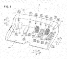
- the operation pedal section 2 includes foot pedals 20 that execute functions of the medical equipment.
- the foot pedals 20 are arranged on a base 2a.
- the foot pedals 20 include coagulation pedals 21, cutting pedals 22, a clutch pedal 23, and a camera pedal 24.
- the operation pedal section 2 is provided with a switch pedal 25.
- the coagulation pedals 21, cutting pedals 22, clutch pedal 23, and camera pedal 24 are operated by being pressed downward.
- the switch pedal 25 is operated by being pressed in the horizontal direction.
- the foot pedals 20 are operated by the foot of the operator O.
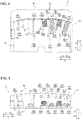
- the operation pedal section 2 includes sensors 26 that detect the presence of the foot operating the foot pedals 20.
- the sensors 26 include sensors 26a, 26b, 26c, 26d, 26e, 26f, and 26g.
- the sensors 26 each include an emitter 261 and a receiver 262.
- the sensors 26 detect the presence of the foot when the light from the emitter 261 is blocked by the foot and the light reception by the receiver 262 is interrupted.
- the sensors 26 are blockage type sensors.
- the sensors 26 are provided to detect that the foot of the operator O is put on any one of the foot pedals 20. In other words, the sensors 26 detect setting of the foot of the operator O at an operation preparation position of the foot pedal 20.
- the detection information detected by the sensors 26 is transmitted to a controller 61, and the controller 61 that receives the detection information determines whether there is the foot operating the corresponding foot pedals 20.
- the coagulation pedals 21 enable surgical instruments to coagulate surgery sites. Specifically, when the coagulation pedals 21 are operated, voltage for coagulation is applied to corresponding one of the surgical instruments 201a, 201b and 201c to coagulate surgery sites.
- the coagulation pedals 21 include a coagulation pedal 21a and a coagulation pedal 21b.
- the coagulation pedal 21a is located to the left (on the X1 side) of the coagulation pedal 21b.
- the coagulation pedal 21a is used in relation to the surgical instrument 201b controlled by the left hand-operation handle 1b.
- the coagulation pedal 21b is used in relation to the surgical instrument 201a controlled by the right hand-operation handle 1a.
- the coagulation pedals 21a and 21b are in a first color. For example, the coagulation pedals 21a and 21b are in blue as the first color.
- the cutting pedals 22 enable the surgical instruments to cut surgery sites. Specifically, when the cutting pedals 22 are operated, voltage for cutting is applied to corresponding one of the surgical instruments 201a, 201b, and 201c to cut surgery sites.
- the cutting pedals 22 include a cutting pedal 22a and a cutting pedal 22b.
- the cutting pedal 22a is located to the left (on the X1 side) of the cutting pedal 22b.
- the cutting pedal 22a is used in relation to the surgical instrument 201b controlled by the left hand-operation handle 1b.
- the cutting pedal 22b is used in relation to the surgical instrument 201a controlled by the right hand-operation handle 1a.
- the cutting pedals 22a and 22b are in a second color different from the first color. For example, the cutting pedals 22a and 22b are in yellow as the second color.
- the right-side foot pedals (the coagulation pedal 21b and the cutting pedal 22b) execute the function of the surgical instrument 201a operated by the right hand-operation handle 1a.
- the left-side foot pedals (the coagulation pedal 21a and the cutting pedal 22a) execute the function of the surgical instrument 201b operated by the left hand-operation handle 1b.
- the coagulation pedal 21b is an example of a first foot pedal and a first coagulation pedal of Claims
- the cutting pedal 22b is an example of the first foot pedal and a first cutting pedal of Claims.
- the coagulation pedal 21a is an example of a second foot pedal and a second coagulation pedal of Claims
- the cutting pedal 22a is an example of the second foot pedal and a second cutting pedal of Claims.
- the clutch pedal 23 is operated to execute a clutch function. Specifically, the clutch pedal 23 is used when temporarily disconnecting the control-related connections between the manipulators 201 and the operation handles 1a and 1b to stop the operation of the surgical instruments.
- the manipulators 201 of the patient-side apparatus 200 does not move even when the operation handles 1a and 1b are operated. For example, when the operation handles 1 come close to the end of the movable region during the operation, it is possible to move the operation handles 1 back to near the central position by operating the clutch pedal 23 and temporarily disconnecting the control-related connections.
- the clutch pedal 23 is operated to temporarily disconnect the whole control-related connections between both the operation handles 1a and 1b and the manipulators 201.
- the clutch switch 11 provided in each of the operation handles 1a and 1b is operated to temporarily disconnect the control-related connections between either of the operation handles 1a and 1b and corresponding one of the manipulators 201, individually.
- the clutch pedal 23 is an example of a fifth foot pedal of Claims.
- the camera pedal 24 is used to control the position and orientation of the endoscope 201d that captures images within the body cavity. That is, the camera pedal 24 executes a function of the endoscope 201d. Specifically, the camera pedal 24 enables control of the endoscope 201d by the operation handles 1. That is, the position and orientation of the endoscope 201d are controllable by the operation handles 1 while the camera pedal 24 is being pressed.
- the endoscope 201d is controlled by using both of the right and left operation handles 1, for example. Specifically, when the operator O rotates the right and left operation handles 1 about the middle point between the right and left operation handles 1, the endoscope 201d is rotated.
- the camera pedal 24 is an example of a third foot pedal of Claims.
- the switch pedal 25 is used to switch the manipulators 201 to be operated by the operation handles 1.
- four manipulators 201 are provided, and within three of the manipulators 201 respectively holding the surgical instruments 201a to 201c, the manipulators 201 operated by the right and left operation handles 1 are switched by operating the switch pedal 25.
- the switch pedal 25 is operated to replace the surgical instrument 201a operated by the right hand-operation handle 1a or the surgical instrument 201b operated by the left hand-operation handle 1b with the surgical instrument 201c, which is provided for replacement.
- the switch pedal 25 is operated by being pressed leftward (in the X1 direction).
- the manipulator 201 operated by the right hand-operation handle 1a is switched by operating the switch pedal 25.
- the manipulator 201 operated by the right hand-operation handle 1a is switched without changing the manipulator 201 operated by the left hand-operation handle 1b.
- the manipulator 201 operated by the left hand-operation handle 1b is switched by operating the switch pedal 25.
- the manipulator 201 operated by the left hand-operation handle 1b is switched without changing the manipulator 201 operated by the right hand-operation handle 1a.
- the switch pedal 25 is an example of a fourth foot pedal of Claims.
- the foot pedals 20 are arranged from the left side (the X1 side) to the right side (the X2 side) in order of the switch pedal 25, the clutch pedal 23, the camera pedal 24, the cutting pedal 22a, the coagulation pedal 21a, the cutting pedal 22b, and the coagulation pedal 21a.
- the arrangement of the foot pedals 20 illustrated in FIGS. 3 to 5 is suitable for operating the pairs of coagulation pedals 21 and cutting pedals 22 assigned to the respective right and left operation handles 1 with only the right foot.
- the pedals arrangement may be as follows: the pair of coagulation pedal 21a and cutting pedal 22a is located to the left (the X1 side) of the clutch pedal 23 and camera pedal 24, and the clutch pedal 23 and camera pedal 24 are located at the center (between the pair of coagulation pedal 21a and cutting pedal 22a and the pair of coagulation pedal 21b and cutting pedal 22b).
- This arrangement is suitable for operating the coagulation pedal 21a and cutting pedal 22a assigned to the left hand-operation handle 1b with the left foot while operating the coagulation pedal 21b and cutting pedal 22b assigned to the right hand-operation handle 1a with the right foot.
- the base 2a on which the foot pedals 20 are arranged is movable in the horizontal direction. Specifically, two sides in the axial direction (the X direction) of the base 2a are connected with a base of the remote control apparatus 100 with sliding bearings, and the operation pedal section 2 is slidable and movable in the depth direction (the front-rear direction, the Y direction).
- the operation pedal section 2 can be moved in the depth direction electrically by a driver device such as a motor provided in the base of the remote control apparatus 100. This makes it possible to adjust the positions of the foot pedals 20 depending on the operation posture, physique, or preference of the operator O.
- the number of the sensors 26 that detect the presence of the foot is greater than the number of the foot pedals 20 that are operated by being pressed downward. Specifically, the number of the provided sensors 26 is seven. On the other hand, the number of the provided foot pedals 20 operated by being pressed downward is six (the coagulation pedals 21a and 21b, cutting pedals 22a and 22b, clutch pedal 23, and camera pedal 24).
- the sensors 26 used to detect the foot moved for the operation are provided near one of the foot pedals 20, and the sensors 26 are used to determine whether there is the foot that is operating or that is trying to operate the one of the foot pedals 20. Specifically, when the controller 61 receives the detection information from the sensors 26 located near the one of the foot pedals 20, the controller 61 determines that the foot of the operator O is set at the operation preparation position of the one of the foot pedals 20.
- a configuration in which one of the sensors 26 (for emitter-receiver type sensors, that is straight light emitted from an emitter) is positioned between a central section of a tip side (the Y1 side) of one foot pedal 20 and a central section of a tip side (the Y1 side) of another foot pedal 20 next to the one foot pedal 20 is expressed simply as "a sensor is positioned between one pedal and another pedal next to the one pedal.”
- the sensor 26 positioned in a central section of a tip side (the Y1 side) of one foot pedal 20 (for the emitter-receiver type sensors, that is a sensor including an emitter that emits straight light passing through the central section of the tip side of the one foot pedal 20) and a sensor between the one pedal and another pedal next to the one pedal are each defined as "a sensor arranged near one pedal.”
- the sensors 26a and 26b detect the foot coming closer to the coagulation pedal 21b. Specifically, when both the sensors 26a and 26b detect the foot, the controller 61 determines that the foot pedal 20 to be operated is the coagulation pedal 21b. The sensors 26b and 26c detect the foot coming closer to the cutting pedal 22b. Specifically, when both the sensors 26b and 26c detect the foot, the controller 61 determines that the foot pedal 20 to be operated is the cutting pedal 22b.
- the sensors 26c and 26d detect the foot coming closer to the coagulation pedal 21a. Specifically, when both the sensors 26c and 26d detect the foot, the controller 61 determines that the foot pedal 20 to be operated is the coagulation pedal 21a. The sensors 26d and 26e detect the foot coming closer to the cutting pedal 22a. Specifically, when both the sensors 26d and 26e detect the foot, the controller 61 determines that the foot pedal 20 to be operated is the cutting pedal 22a.
- the sensor 26f detects the foot coming closer to the camera pedal 24. Specifically, when the sensor 26f detects the foot, the controller 61 determines that the foot pedal 20 to be operated is the camera pedal 24. The sensor 26g detects the foot coming closer to the clutch pedal 23. Specifically, when the sensor 26g detects the foot, the controller 61 determines that the foot pedal 20 to be operated is the clutch pedal 23.
- the emitter 261 includes a light-emitting element such as an LED.
- the emitter 261 is configured to emit visible light or invisible light such as infrared light.
- the receiver 262 includes a light-receiving element.
- the corresponding emitter 261 and receiver 262 are arranged along the Y direction in the plan view. Specifically, as illustrated as a broken line in FIGS. 3 and 5 , the light from the emitter 261 is emitted substantially along the Y direction in the plan view.
- the corresponding emitter 261 and receiver 262 are arranged so that their arrangement orientation is parallel to each other in the plan view.
- the emitter 261 is configured to emit the light obliquely downward.
- the coagulation pedal 21a and the cutting pedal 22a are used as a pair, while the coagulation pedal 21b and the cutting pedal 22b are used as a pair.
- a pair of forceps e.g., a grasper
- high voltage is applied for cutting
- voltage lower than the cutting case is applied for coagulating.
- coagulation pedal 21a 21b
- cutting pedal 22a 22b
- a sealing device for coagulating may also be used as a dedicated tool or used concurrently with another tool. This is because the sealing device often has an additional function such as automatic termination of power supply that is executed when coagulating is completed.
- a pair of bipolar forceps F1, a pair of monopolar forceps F2, and a sealing device F3 as the medical equipment and the endoscope 201d are attached to the four manipulators 201.
- the positional relationship between the four manipulators 201 is recognized by the position detector provided for each manipulator.
- the positional relationship between the manipulators in the right-left direction is determined based on the positions thereof seen from the platform 203.
- the pair of monopolar forceps F2 is located to the left of one of the manipulators 201 to which the endoscope 201d is attached, and the pair of bipolar forceps F1 and the sealing device F3 are located to the right of the manipulator 201 to which the endoscope 201d is attached in this order from left.
- the manipulator 201 to which the surgical instrument 201b is attached is assigned to the left-side foot pedals (the coagulation pedal 21a and the cutting pedal 22a), and the manipulator 201 to which the surgical instrument 201a, which is a surgical instrument to the right of the manipulator 201 to which the surgical instrument 201b is attached, is assigned to right-side foot pedals (the coagulation pedal 21b and cutting pedal 22b).
- the coagulation pedal 21a and 21b the cutting pedal 22b
- the pair of monopolar forceps F2 is assigned to the left-side foot pedals (the coagulation pedal 21a and the cutting pedal 22a), while the pair of bipolar forceps F1 is assigned to the right-side foot pedals (the coagulation pedal 21b and the cutting pedal 22b).
- the manipulators 201 are assigned to the left-side foot pedals and the right-side foot pedals in order from the one on the leftmost side of the manipulator 201 to which the endoscope 201d is attached.
- the manipulator 201 is assigned to the left-side foot pedals.
- the pair of bipolar forceps F1 and the pair of monopolar forceps F2 are replaced with each other by an assistant (a nurse, for example).
- the types of the surgical instruments 201a and 201b are specified when the surgical instruments 201a and 201b are attached to the manipulators 201.
- the IC of the interface may store information including model numbers of the instruments.
- the pair of bipolar forceps F1 is assigned to the left-side foot pedals (the coagulation pedal 21a and the cutting pedal 22a).
- the pair of monopolar forceps F2 is assigned to the right-side foot pedals (the coagulation pedal 21b and the cutting pedal 22b).
- the pair of monopolar forceps F2 and the sealing device F3 are replaced with each other by an assistant (a nurse, for example).
- the types of the surgical instruments 201a and 201b are specified when the surgical instruments 201a and 201b are attached to the manipulators 201.
- the pair of bipolar forceps F1 continues to be assigned to the left-side foot pedals (the coagulation pedal 21a and the cutting pedal 22a).
- the sealing device F3 is assigned to the right-side foot pedals (the coagulation pedal 21b and the cutting pedal 22b).
- the switch pedal 25 is operated to change which of the two manipulators 201 located on the right side is being activated. Specifically, the manipulators 201 controlled by the operation handles 1 are switched. The manipulator 201 to which the pair of bipolar forceps F1 is attached is controlled with the left hand-operation handle 1b while the manipulator 201 to which the pair of monopolar forceps F2 is attached is controlled with the right hand-operation handle 1a. The pair of bipolar forceps F1 continues to be assigned to the left-side foot pedals (the coagulation pedal 21a and the cutting pedal 22a). The pair of monopolar forceps F2 is assigned to the right-side foot pedals (the coagulation pedal 21b and the cutting pedal 22b).
- the switch pedal 25 is operated to change which of the two manipulators 201 on the right side is being activated. Specifically, the manipulators 201 to be controlled by the operation handles 1 are switched. The manipulator 201 to which the pair of bipolar forceps F1 is attached is controlled with the left hand-operation handle 1b while the manipulator 201 to which the sealing device F3 is attached is controlled with the right hand-operation handle 1a. The pair of bipolar forceps F1 continues to be assigned to the left-side foot pedals (the coagulation pedal 21a and the cutting pedal 22a). The sealing device F3 is assigned to the right-side foot pedals (the coagulation pedal 21b and the cutting pedal 22b).
- a simple grasper which works without electricity is used when strong grip is mainly necessary.
- Such surgical instruments that cannot be supplied with current are not controlled with the coagulation pedals 21 (21a and 21b) and the cutting pedals 22 (22a and 22b) and are therefore not assigned to the coagulation pedals 21 and cutting pedals 22.
- the assignment of the coagulation pedals 21 (21a and 21b) and cutting pedals 22 (22a and 22b) is configured so that the manipulator 201 holding a surgical instrument that cannot be supplied with current is ignored.
- the left-side foot pedals (the coagulation pedal 21a and the cutting pedal 22a) and right-side foot pedals (the coagulation pedal 21b and the cutting pedal 22b) may be assigned by another rule.
- the manipulators 201 to the right and left of the manipulator 201 to which the endoscope 201d is attached may be always assigned to the foot pedals.
- the one manipulator 201 to the left of the manipulator 201 to which the endoscope 201d is attached may be assigned to the left-side foot pedals (the coagulation pedal 21a and the cutting pedal 22a), while the left manipulator 201 among the two manipulators 201 located to the right of the manipulator 201 to which the endoscope 201d is attached is assigned to the right-side foot pedals (the coagulation pedal 21b and the cutting pedal 22b).
- the display device 3 displays an image captured by the endoscope 201d.
- the display device 3 includes a scope type display device or a non-scope type display device.
- the display device 3 is the scope type display device.
- the scope type display device is a display unit that the operator O looks into, for example.
- the non-scope type display device is a concept including an open-type display unit that the operator O looks at without looking into and that has a flat screen, such as a normal personal computer display.
- the control apparatus 6 such as a computer includes a controller 61, a storage 62, and an image controller 63, for example.
- the controller 61 includes a computing element such as a CPU.
- the storage 62 includes one or more memories, such as a ROM and a RAM.
- the control apparatus 6 is configured to control at least the endoscope 201d and the display device 3.
- the control apparatus 6 may be composed of a single controller performing centralized control or may be composed of plural controllers that perform decentralized control in cooperation with each other.
- the controller 61 determines whether the action mode instruction inputted by the operation handles 1 is to be executed by the surgical instruments 201a to 201c or to be executed by the endoscope 201d, depending on the state of the operation pedal section 2.
- the controller 61 transmits a signal to operate a corresponding one of the manipulators 201 based on the determination result and operations through the operation handles 1.
- the controller 61 receives the detection information on the presence of the foot of the operator O from the sensors 26 and determines whether there is the foot of the operator O. When it is determined that there is the foot of the operator O, the controller 61 controls the display device 3 to display the corresponding screen.
- the storage 62 stores control programs corresponding to the types of the surgical instruments 201a to 201c, for example.
- the controller 61 reads the stored control programs according to the types of the attached surgical instruments 201a to 201c.
- the action mode instructions from the operation handles 1 and/or the operation pedal section 2 of the remote control apparatus 100 thereby causes the respective surgical instruments 201a to 201c to perform proper motions.
- the image controller 63 transmits an image acquired by the endoscope 201d to the display device 3.
- the image controller 63 modifies the image if necessary.
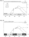
- the control apparatus 6 is configured to display a graphical user interface 32 on the display device 3 while overlapping the graphical user interface 32 on an image 31 captured by the endoscope 201d.
- the graphical user interface 32 includes a first area 321 showing information on the surgical instrument 201a operated by the right hand-operation handle 1a, a second area 322 showing information on the surgical instrument 201b operated by the left hand-operation handle 1b, and a third area 323 showing information on the endoscope 201d, which are arranged side by side in this order from right to left.
- the control apparatus 6 is configured to display the graphical user interface 32 on the display device 3 while overlapping the graphical user interface 32 on the image 31 captured by the endoscope 201d.
- the graphical user interface 32 includes the first area 321 showing the information on the surgical instrument 201a operated by the right hand-operation handle 1a, the second area 322 showing the information on the surgical instrument 201b operated by the left hand-operation handle 1b, and the third area 323 showing the information on the endoscope 201d.
- the first area 321, second area 322, and third area 323 are arranged in the same order as the arrangement order of the right-side foot pedals (the coagulation pedal 21b and the cutting pedal 22b), left-side foot pedals (the coagulation pedal 21a and the cutting pedal 22a), and camera pedal 24 on the operation pedal section 2.
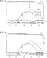
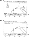
- the graphical user interface 32 displayed on the display device 3 includes the first area 321, the second area 322, the third area 323, a fourth area 324, and a fifth area 325. Additionally, the graphical user interface 32 includes a status area 326. Moreover, the graphical user interface 32 includes a pop-up area 327a (see FIG. 9 ), a pop-up area 327b (see FIG. 13 ), a pop-up area 327c (see FIG. 15 ), and a pop-up area 327d (see FIG. 17 ). Furthermore, the graphical user interface 32 includes a central area in which a level 328 (see FIG. 14 ) for the endoscope 201d is displayed. The graphical user interface 32 also includes an error notification area 329a (see FIG. 20 ) and an error notification area 329b (see FIG. 21 ).
- the first area 321, second area 322, third area 323, fourth area 324, and fifth area 325 of the graphical user interface 32 are arranged side by side in a lower end region of the display device 3.
- the first area 321, second area 322, third area 323, fourth area 324, and fifth area 325 of the graphical user interface 32 may be arranged side by side in an upper end region of the display device 3.
- the pieces of information on the surgical instrument 201a, surgical instrument 201b, and endoscope 201d are displayed on the upper side or the lower side of the display device 3.
- the pop-up areas 327a and 327b of the graphical user interface 32 are arranged on the left side in the right-left direction and near the center in the up-down direction of the display device 3.
- the pop-up areas 327c and 327d of the graphical user interface 32 are arranged on the right side in the right-left direction and near the center in the up-down direction of the display device 3.
- the status area 326 and the error notification area 329a of the graphical user interface 32 are arranged in the upper end region of the display device 3.
- the error notification area 329b is arranged above the second area 322 of the graphical user interface 32.
- the first area 321 displays the type of the surgical instrument 201a being operated by the right-hand operation handle 1a.
- the second area 322 displays the type of the surgical instrument 201b being operated by the left-hand operation handle 1b.
- the third area 323 displays the information on the endoscope 201d.
- the fourth area 324 is arranged between the first area 321 and the second area 322.
- the fourth area 324 displays the information on the replacement surgical instrument 201c. Specifically, the fourth area 324 displays the type of the replacement surgical instrument 201c.
- the operator O can easily grasp, on the screen of the display device 3, the information on the replacement surgical instrument 201c, which is to be replaced with the surgical instrument 201a or the surgical instrument 201b and operated by the operation handle 1a or the operation handle 1b.
- the information in the fourth area 324 is displayed with paler color than the information in the first area 321 and second area 322. In other words, the information in the fourth area 324 is displayed to be more inconspicuous than the information in the first area 321 and second area 322.
- the fifth area 325 is arranged to the left of the second area 322.
- the fifth area 325 displays the information on the clutch function.
- the fifth area 325 displays the operation state of the clutch pedal 23.
- the status area 326 displays the status of the surgical system 400. For example, the status area 326 displays duration of surgery procedure. The status area 326 also displays brightness adjustment information and contrast adjustment information of the display device 3.
- the pop-up areas 327a to 327d are arranged in positions different from those of the first area 321, second area 322, and third area 323.
- the pop-up areas 327a to 327d display information, based on a fact that at least one of the sensors 26 detects setting of the foot of the operator O at the operation preparation position of the corresponding foot pedal 20.
- information on the foot pedal 20 is displayed in not only the corresponding area but in a different position as well. This allows the operator O to easily recognize setting of the foot pedal 20 to be operated at the operation preparation position.
- the pop-up area 327a displays the information on the clutch pedal 23 when the foot of the operator O is set at the operation preparation position of the clutch pedal 23.
- the pop-up area 327a displays information for a predetermined time (e.g., three seconds). Specifically, the display of the information in the pop-up area 327a ends when the foot of the operator O is moved from the operation preparation position of the clutch pedal 23, when the clutch pedal 23 is operated, or after a lapse of the predetermined time.
- the pop-up area 327b displays information on the camera pedal 24 when the foot of the operator O is set at the operation preparation position of the camera pedal 24.
- the pop-up area 327b displays information for a predetermined time (e.g., three seconds). Specifically, the display of the information in the pop-up area 327b ends when the foot of the operator O is moved from the operation preparation position of the camera pedal 24, when the camera pedal 24 is operated, or after a lapse of the predetermined time.
- the pop-up area 327c displays information on the cutting pedals 22 when the foot of the operator O is set at the operation preparation position of the cutting pedal 22a or 22b.
- the pop-up area 327c displays information for a predetermined time (e.g., three seconds). Specifically, the display of the information in the pop-up area 327c ends when the foot of the operator O is moved from the operation preparation position of the cutting pedal 22a or 22b, when the cutting pedal 22a or 22b is operated, or after a lapse of the predetermined time.
- the pop-up area 327d displays information on the coagulation pedals 21 when the foot of the operator O is set at the operation preparation position of the coagulation pedal 21a or 21b.
- the pop-up area 327d displays information for a predetermined time (e.g., three seconds). Specifically, the display of the information in the pop-up area 327d ends when the foot of the operator O is moved from the operation preparation position of the coagulation pedal 21a or 21b, when the coagulation pedal 21a or 21b is operated, or after a lapse of the predetermined time.
- the level 328 for the endoscope 201d is displayed on the display device 3 when the camera pedal 24 is operated.
- the operator O can easily change the orientation of the endoscope 201d through operation referring to the displayed level 328.
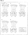
- control apparatus 6 is configured to change the display form of a corresponding area out of the first area 321, the second area 322, and the third area 323, based on a fact that at least one of the sensors 26 detects setting of the foot of the operator O at the operation preparation position of at least one foot pedal 20 out of the right-side foot pedals (the coagulation pedal 21b and the cutting pedal 22b), the left-side foot pedals (the coagulation pedal 21a and the cutting pedal 22a), and the camera pedal 24.
- the graphical user interface 32 corresponding to the foot pedal 20 is displayed on the display device 3 with the display form of the area of the graphical user interface 32 changed. Consequently, the operator O does not need to check with the eyes that actually the foot is located on which foot pedal 20.
- the operator O can confirm the foot pedal 20 to be operated while keeping eyes on the display device 3.
- the changing of the display form of an area includes at least one of display color change, inverted display, display change of an area frame line, and zoom/zoom-out of the display area.
- the control apparatus 6 is configured to display the information with the first color in a corresponding area out of the first area 321 and the second area 322, based on a fact that at least one of the sensors 26 detects setting of the foot of the operator O at the operation preparation position of the coagulation pedal 21a or 21b. Additionally, the control apparatus 6 is configured to display the information with the second color in a corresponding area out of the first area 321 and the second area 322, based on a fact that at least one of the sensors 26 detects setting of the foot of the operator O at the operation preparation position of the cutting pedal 22a or 22b. It is possible to display the information in the corresponding areas with different colors between the case of operating the coagulation pedal 21a or 21b and the case of operating the cutting pedal 22a or 22b. Consequently, the operator O can easily recognize whether the foot pedal 20 to be operated is the coagulation pedal 21a or 21b or the cutting pedal 22a or 22b while keeping eyes on the display device 3.
- the control apparatus 6 is configured, when the foot pedal 20 is operated, to display, in the corresponding area, the information in a display form different from a display form in a case where the foot of the operator O is set at the operation preparation position of the foot pedal 20. That is, a display form in the state where the foot of the operator O is set at the operation preparation position is different from a display form in the state where the foot of the operator O is operated. Consequently, the operator O can easily recognize whether the foot pedal 20 is in an operation preparation state or in an operated state.
- the areas of the graphical user interface 32 are configured to display the operation states of the corresponding foot pedals 20. Thus, the operator O can easily grasp the operation states of the foot pedals 20.
- the first area 321 displays the information on the right-side foot pedals (the coagulation pedal 21b and the cutting pedal 22b).
- the frame line of the first area 321 is displayed with the color of the corresponding foot pedal 20 (the coagulation pedal 21b or the cutting pedal 22b).
- the operator O can easily grasp the execution state of the function of the surgical instrument 201a operated by the right-side foot pedals (the coagulation pedal 21b and the cutting pedal 22b) through the display of the first area 321.
- the first area 321 displays the information on the coagulation pedal 21b or the cutting pedal 22b such that the display is distinguished from that in the case where the foot of the operator O is set at the operation preparation position. For example, when the coagulation pedal 21b or the cutting pedal 22b is operated, the entirety of the first area 321 is displayed with the color of the corresponding foot pedal 20 (the coagulation pedal 21b or the cutting pedal 22b). Thus, the operator O can easily grasp the operation state of the coagulation pedal 21b or the cutting pedal 22b through the display of the first area 321.
- the first area 321 displays the information on the coagulation pedal 21b.
- the first area 321 displays the information on the cutting pedal 22b. Consequently, the operator O can easily grasp the execution states of the coagulation function and the cutting function by the surgical instrument 201a that is operated by the right hand-operation handle 1a through the display of the first area 321.
- the second area 322 displays the information on the left-side foot pedals (the coagulation pedal 21a and the cutting pedal 22a). For example, when the foot of the operator O is set at the operation preparation position of the coagulation pedal 21a or the cutting pedal 22a, the frame line of the second area 322 is displayed with the color of the corresponding foot pedal 20 (the coagulation pedal 21a or the cutting pedal 22a). Thus, the operator O can easily grasp the execution state of the function of the surgical instrument 201b operated by the left-side foot pedals (the coagulation pedal 21a and the cutting pedal 22a) through the display of the second area 322.
- the second area 322 displays the information on the coagulation pedal 21a or the cutting pedal 22a such that the display is distinguished from that in the case where the foot of the operator O is set at the operation preparation position. For example, when the coagulation pedal 21a or the cutting pedal 22a is operated, the entirety of the second area 322 is displayed with the color of the corresponding foot pedal 20 (the coagulation pedal 21a or the cutting pedal 22a). Thus, the operator O can easily grasp the operation state of the coagulation pedal 21a or the cutting pedal 22a through the display of the second area 322.
- the second area 322 displays the information on the coagulation pedal 21a.
- the cutting pedal 22a is operated, the second area 322 displays the information on the cutting pedal 22a. Consequently, the operator O can easily grasp the execution states of the coagulation function and the cutting function by the surgical instrument 201b that is operated by the left hand-operation handle 1b through the display of the second area 322.
- the third area 323 displays the information on the camera pedal 24.
- the frame line of the third area 323 is emphasized.
- the operator O can easily grasp the execution state of the function of the endoscope 201d operated by the camera pedal 24 through the display of the third area 323.
- the third area 323 displays the information on the camera pedal 24 such that the display is distinguished from that in the case where the foot of the operator O is set at the operation preparation position.
- the background color and the text color of the third area 323 are inverted.
- the operator O can easily grasp the operation state of the camera pedal 24 through the display of the third area 323.
- the switch pedal 25 when the switch pedal 25 is operated, the surgical instrument operated by the left hand-operation handle 1b is switched from the surgical instrument 201b to the surgical instrument 201c.
- the background colors and the text colors of the second area 322 and the fourth area 324 are inverted.
- the operator O can easily recognize the switching of the surgical instruments.
- the frame line of the fifth area 325 is emphasized.
- the information on the clutch pedal 23 is popped up and displayed in the pop-up area 327a.
- the display of the pop-up area 327a ends after a lapse of the predetermined time. In this case, the emphasized display of the frame line of the fifth area 325 continues.
- the control-related connections between the operation handles 1 and the manipulators 201 are temporarily disconnected.
- the background color and the text color of the fifth area 325 displaying the information on the clutch pedal 23 are inverted.
- the background color and the text color of the first area 321 displaying the information on the surgical instrument 201a in which the control-related connection is temporarily disconnected are inverted.
- the background color and the text color of the second area 322 displaying the information on the surgical instrument 201b in which the control-related connection is temporarily disconnected are inverted.
- the frame line of the third area 323 is emphasized. Additionally, the information on the camera pedal 24 is popped up and displayed in the pop-up area 327b. Even when the foot of the operator O continues to be set at the operation preparation position of the camera pedal 24, the display of the pop-up area 327b ends after a lapse of the predetermined time. In this case, the emphasized display of the frame line of the third area 323 continues.
- the position and orientation of the endoscope 201d can be controlled by the operation handles 1a and 1b.
- the background color and the text color of the third area 323 displaying the information on the camera pedal 24 are inverted. Additionally, the level 328 for the endoscope 201d is displayed in the central area.
- the frame line of the first area 321 is emphasized. Specifically, more than left half of the frame line is emphasized by the second color of the cutting pedal 22b. The rest of the frame line is emphasized by the first color of the coagulation pedal 21b.
- the operator O can more effectively recognize setting of the foot at the operation preparation position of the cutting pedal 22b out of the cutting pedal 22b and the coagulation pedal 21b.
- the information on the cutting pedal 22b is popped up and displayed in the pop-up area 327c.
- the display of the pop-up area 327c ends after a lapse of the predetermined time. In this case, the emphasized display of the frame line of the first area 321 continues.
- the frame line of the second area 322 is emphasized also when the foot of the operator O is set at the operation preparation position of the cutting pedal 22a corresponding to the surgical instrument 201b being operated by the left hand.
- the background of the second area 322 displaying the information on the cutting pedal 22a is displayed with the second color of the cutting pedal 22a.
- the frame line of the first area 321 is emphasized. Specifically, more than right half of the frame line is emphasized by the first color of the coagulation pedal 21b. The rest of the frame line is emphasized by the second color of the cutting pedal 22b.
- the operator O can more effectively recognize setting of the foot at the operation preparation position of the coagulation pedal 21b out of the cutting pedal 22b and the coagulation pedal 21b.
- the information on the coagulation pedal 21b is popped up and displayed in the pop-up area 327d. Even when the foot of the operator O continues to be set at the operation preparation position of the coagulation pedal 21b, the display of the pop-up area 327d ends after a lapse of the predetermined time. In this case, the emphasized display of the frame line of the first area 321 continues.
- the frame line of the second area 322 is emphasized also when the foot of the operator O is set at the operation preparation position of the coagulation pedal 21a corresponding to the surgical instrument 201b being operated by the left hand.
- the background of the second area 322 displaying the information on the coagulation pedal 21a is displayed with the first color of the coagulation pedal 21a.
- the frame line of the second area 322 is emphasized. Specifically, more than left half of the frame line is emphasized by the second color of the cutting pedal 22a. The rest of the frame line is emphasized by the first color of the coagulation pedal 21a. Additionally, the information on the cutting pedal 22a is popped up and displayed in the pop-up area 327c. Moreover, the frame line of the fifth area 325 is emphasized. The information on the clutch pedal 23 is popped up and displayed in the pop-up area 327a.
- a notification to indicate that the functions are restricted is displayed in the error notification area 329a.
- a notification to indicate that unfunctional operation is tried to be executed is popped up and displayed on the upper side of the area corresponding to the surgical instrument. In this case, no voltage is applied to the surgical instrument even if the cutting pedals 22 and the coagulation pedals 21 are operated.
- the error notification is displayed in the error notification area 329b.
- the foot pedals on the operation pedal section include the coagulation pedals and the cutting pedals in the example illustrated in the above-described one or more embodiments, but the invention is not limited thereto.
- the foot pedals on the operation pedal section may include a foot pedal that executes a function of medical equipment other than the coagulation pedals and the cutting pedals.
- the sensor is the blockage type in the example illustrated in the above-described one or more embodiments, but the invention is not limited thereto.
- the sensor may be a transparent type or a reflection type. Otherwise, the sensor may detect the presence of the foot without using light. For example, the detection may be performed by using a soundwave or a coil.
Landscapes
- Health & Medical Sciences (AREA)
- Life Sciences & Earth Sciences (AREA)
- Engineering & Computer Science (AREA)
- Surgery (AREA)
- Biomedical Technology (AREA)
- Public Health (AREA)
- General Health & Medical Sciences (AREA)
- Medical Informatics (AREA)
- Nuclear Medicine, Radiotherapy & Molecular Imaging (AREA)
- Animal Behavior & Ethology (AREA)
- Molecular Biology (AREA)
- Heart & Thoracic Surgery (AREA)
- Veterinary Medicine (AREA)
- Pathology (AREA)
- Radiology & Medical Imaging (AREA)
- Physics & Mathematics (AREA)
- Robotics (AREA)
- Optics & Photonics (AREA)
- Biophysics (AREA)
- Primary Health Care (AREA)
- Epidemiology (AREA)
- Oral & Maxillofacial Surgery (AREA)
- Human Computer Interaction (AREA)
- Business, Economics & Management (AREA)
- General Business, Economics & Management (AREA)
- Mechanical Engineering (AREA)
- Plasma & Fusion (AREA)
- Otolaryngology (AREA)
- Gynecology & Obstetrics (AREA)
- Urology & Nephrology (AREA)
- Manipulator (AREA)
Claims (15)
- Système chirurgical (400), comprenant :des manipulateurs (201) qui supportent respectivement un endoscope (201d), un premier instrument chirurgical (201a), et un deuxième instrument chirurgical (201b) ;un appareil de commande distant (100) qui inclut un dispositif d'affichage (3) configuré pour afficher une image capturée par l'endoscope, une première manette d'actionnement (1a) pour actionner le premier instrument chirurgical, une deuxième manette d'actionnement (1b) pour actionner le deuxième instrument chirurgical, et une section de pédales d'actionnement (2) incluant des pédales de pied (20) ; etun appareil de commande (63) configuré pour commander au moins le dispositif d'affichage, dans lequella section de pédales d'actionnement inclut des capteurs de type sans contact (26) configurés pour détecter la présence d'un pied d'un opérateur se rapprochant des pédales de pied respectives,les pédales de pied incluent une première pédale de pied (21b, 22b) pour exécuter une fonction du premier instrument chirurgical, une deuxième pédale de pied (21a, 22a) pour exécuter une fonction du deuxième instrument chirurgical, et une troisième pédale de pied (24) pour exécuter une fonction de l'endoscope,l'appareil de commande est configuré pour afficher sur le dispositif d'affichage une surface d'utilisateur graphique (32) empiétant sur l'image capturée par l'endoscope, l'interface d'utilisateur graphique incluant une première zone (321) qui affiche des informations sur le premier instrument chirurgical, une deuxième zone (322) qui affiche des informations sur le deuxième instrument chirurgical, et une troisième (323) zone qui affiche des informations sur l'endoscope, qui sont agencées dans celle-ci, etl'appareil de commande est en outre configuré pour changer, quand le pied de l'opérateur se rapprochant de l'une au moins des première à troisième pédales de pied est détecté par l'un au moins des capteurs, une forme d'affichage de l'une au moins des première à troisième zones correspondante.
- Système chirurgical selon a revendication 1, dans lequel
l'interface d'utilisateur graphique inclut la première zone, la deuxième zone, et la troisième zone dans une région d'extrémité inférieure ou dans une région d'extrémité supérieure du dispositif d'affichage. - Système chirurgical selon la revendication 1 ou 2, dans lequel
le changement de la forme d'affichage de l'une au moins des zones correspondante inclut l'un au moins d'un changement de couleur d'affichage, d'un affichage inversé, et d'un changement d'affichage d'une ligne de cadre de l'une au moins des zones correspondante. - Système chirurgical selon l'une quelconque des revendications 1 à 3, dans lequel
l'appareil de commande est configuré pour afficher, quand le pied de l'opérateur se rapprochant de l'une au moins des première à troisième pédales de pied est détecté par l'un au moins des capteurs, des informations sur la au moins une pédale de pied dont le pied de l'opérateur se rapproche, les informations étant affichées dans une position différente de celles des première à troisième zones. - Système chirurgical selon l'une quelconque des revendications 1 à 4, dans lequella première zone affiche un type du premier instrument chirurgical,la deuxième zone affiche un type du deuxième instrument chirurgical, etla troisième zone affiche des informations sur l'endoscope.
- Système chirurgical selon la revendication 5, dans lequella première pédale de pied inclut une première pédale de coagulation (21b) pour coaguler un site chirurgical et une première pédale de coupe (22b) pour couper le site chirurgical,la deuxième pédale de pied inclut une deuxième pédale de coagulation (21a) pour coaguler le site chirurgical et une deuxième pédale de coupe (22a) pour couper le site chirurgical,quand la première pédale de coagulation est actionnée, la première zone affiche des informations sur la première pédale de coagulation, différentes de celles dans le cas où le pied de l'opérateur se rapproche de la première pédale de coagulation,quand la première pédale de coupe est actionnée, la première zone affiche des informations sur la première pédale de coupe, différentes de celles dans le cas où le pied de l'opérateur se rapproche de la première pédale de coupe,quand la deuxième pédale de coagulation est actionnée, la deuxième zone affiche des informations sur la deuxième pédale de coagulation, différentes de celles dans le cas où le pied de l'opérateur se rapproche de la deuxième pédale de coagulation, etquand la deuxième pédale de coupe est actionnée, la deuxième zone affiche des informations sur la deuxième pédale de coupe, différentes de celles dans le cas où le pied de l'opérateur se rapproche de la deuxième pédale de coupe.
- Système chirurgical selon la revendication 6, dans lequella première pédale de coagulation et la deuxième pédale de coagulation sont d'une première couleur,la première pédale de coupe et la deuxième pédale de coupe sont d'une deuxième couleur, différente de la première couleur, etl'appareil de commande est configuré pour afficher, quand le pied de l'opérateur se rapprochant de l'une de la première pédale de coagulation et de la deuxième pédale de coagulation de pied est détecté par l'un au moins des capteurs, des informations avec la première couleur dans l'une correspondante de la première zone et de la deuxième zone, etl'appareil de commande est en outre configuré pour afficher, quand le pied de l'opérateur se rapprochant de l'une de la première pédale de coupe et de la deuxième pédale de coupe est détecté par l'un au moins des capteurs, des informations avec la deuxième couleur dans l'une correspondante de la première zone et de la deuxième zone.
- Système chirurgical selon l'une quelconque des revendications 1 à 7, dans lequel
l'appareil de commande est configuré pour afficher, quand l'une des première à troisième pédales de pied est actionnée, des informations dans l'une des première à troisième zones correspondante, les informations étant affichées dans une forme d'affichage différente d'une forme d'affichage dans un cas où le pied de l'opérateur se rapproche de la pédale de pied. - Système chirurgical selon l'une quelconque des revendications 1 à 8, dans lequell'un des manipulateurs supporte un instrument chirurgical de remplacement (201c),la section de pédale d'actionnement inclut en outre une quatrième pédale de pied (25) pour remplacer l'un du premier instrument chirurgical à actionner par la première manette d'actionnement et du deuxième instrument chirurgical à actionner par la deuxième manette d'actionnement avec l'instrument chirurgical de remplacement, etl'interface utilisateur graphique inclut une quatrième zone (324) qui est agencée entre la première zone et la deuxième zone et affiche des informations sur l'instrument chirurgical de remplacement.
- Système chirurgical selon l'une quelconque des revendications 1 à 9, dans lequella section de pédale d'actionnement inclut en outre une cinquième pédale de pied (23) pour exécuter une fonction de débrayage, etl'interface d'utilisateur graphique inclut une cinquième zone (325) qui affiche des informations sur la fonction de débrayage.
- Système chirurgical selon l'une quelconque des revendications 1 à 10, dans lequel
l'appareil de commande est configuré pour afficher, quand la troisième pédale de pied est actionnée, l'interface d'utilisateur graphique incluant l'affichage d'un niveau (328) pour l'endoscope, empiétant sur l'image capturée par l'endoscope. - Système chirurgical selon l'une quelconque des revendications 1 à 11, dans lequel
chacune des première à troisième zones de l'interface d'utilisateur graphique affiche un état d'actionnement d'une pédale de pied correspondante. - Procédé d'affichage d'informations dans un système chirurgical (400),le système chirurgical incluant : des manipulateurs (201) qui supportent respectivement un endoscope (201d), un premier instrument chirurgical (201a), et un deuxième instrument chirurgical (201b) ; un appareil de commande distant (100) qui inclut un dispositif d'affichage (3) configuré pour afficher une image capturée par l'endoscope, une première manette d'actionnement (la) pour actionner le premier instrument chirurgical, et une deuxième manette d'actionnement (1b) pour actionner le deuxième instrument chirurgical ; une section de pédales d'actionnement incluant des pédales de pied ; et un appareil de commande configuré pour commander au moins le dispositif d'affichage,la section de pédales d'actionnement inclut des capteurs de type sans contact (26) qui détectent la présence d'un pied d'un opérateur se rapprochant des pédales de pied respectives,les pédales de pied incluent une première pédale de pied (21b, 22b) pour exécuter une fonction du premier instrument chirurgical, une deuxième pédale de pied (21a, 22a) pour exécuter une fonction du deuxième instrument chirurgical, et une troisième pédale de pied (24) pour exécuter une fonction de l'endoscope, le procédé comprenant :afficher une surface d'utilisateur graphique (32) incluant une première zone (321) qui affiche des informations sur le premier instrument chirurgical, une deuxième zone (322) qui affiche des informations sur le deuxième instrument chirurgical, et une troisième zone (323) qui affiche des informations sur l'endoscope ; etchanger, quand le pied de l'opérateur se rapprochant de l'une au moins des première à troisième pédales de pied est détecté par l'un au moins des capteurs, une forme d'affichage de l'une au moins des première à troisième zones correspondante.
- Procédé selon la revendication 13, dans lequel
changer la forme d'affichage de l'une au moins des zones correspondante inclut au moins un changement de couleur d'affichage, un affichage inversé, et un changement d'affichage d'une ligne de cadre de l'une au moins des zones correspondante. - Procédé selon la revendication 13, dans lequel
l'affichage, quand la troisième pédale de pied est actionnée, de l'interface d'utilisateur graphique inclut l'affichage d'un niveau (328) pour l'endoscope, en empiétant sur l'image capturée par l'endoscope.
Applications Claiming Priority (1)
| Application Number | Priority Date | Filing Date | Title |
|---|---|---|---|
| JP2018179277A JP6898285B2 (ja) | 2018-09-25 | 2018-09-25 | 手術システムおよび表示方法 |
Publications (2)
| Publication Number | Publication Date |
|---|---|
| EP3628207A1 EP3628207A1 (fr) | 2020-04-01 |
| EP3628207B1 true EP3628207B1 (fr) | 2022-05-18 |
Family
ID=68069564
Family Applications (1)
| Application Number | Title | Priority Date | Filing Date |
|---|---|---|---|
| EP19199588.5A Active EP3628207B1 (fr) | 2018-09-25 | 2019-09-25 | Système chirurgical et procédé d'affichage d'informations dans le système |
Country Status (3)
| Country | Link |
|---|---|
| US (1) | US20200093552A1 (fr) |
| EP (1) | EP3628207B1 (fr) |
| JP (2) | JP6898285B2 (fr) |
Families Citing this family (25)
| Publication number | Priority date | Publication date | Assignee | Title |
|---|---|---|---|---|
| AU2019345238A1 (en) * | 2018-09-17 | 2021-03-18 | Covidien Lp | Foot pedal assignment for robotic surgical systems |
| US12016566B2 (en) | 2020-10-02 | 2024-06-25 | Cilag Gmbh International | Surgical instrument with adaptive function controls |
| US11748924B2 (en) | 2020-10-02 | 2023-09-05 | Cilag Gmbh International | Tiered system display control based on capacity and user operation |
| US11911030B2 (en) | 2020-10-02 | 2024-02-27 | Cilag Gmbh International | Communication capability of a surgical device with component |
| US12064293B2 (en) | 2020-10-02 | 2024-08-20 | Cilag Gmbh International | Field programmable surgical visualization system |
| US11672534B2 (en) | 2020-10-02 | 2023-06-13 | Cilag Gmbh International | Communication capability of a smart stapler |
| US11883052B2 (en) | 2020-10-02 | 2024-01-30 | Cilag Gmbh International | End effector updates |
| US12213801B2 (en) | 2020-10-02 | 2025-02-04 | Cilag Gmbh International | Surgical visualization and particle trend analysis system |
| US11830602B2 (en) | 2020-10-02 | 2023-11-28 | Cilag Gmbh International | Surgical hub having variable interconnectivity capabilities |
| US11992372B2 (en) | 2020-10-02 | 2024-05-28 | Cilag Gmbh International | Cooperative surgical displays |
| US11963683B2 (en) | 2020-10-02 | 2024-04-23 | Cilag Gmbh International | Method for operating tiered operation modes in a surgical system |
| US12484897B2 (en) | 2020-10-02 | 2025-12-02 | Cilag Gmbh International | Surgical instrument with adaptive configuration control |
| US12580072B2 (en) | 2020-10-02 | 2026-03-17 | Cilag Gmbh International | Cloud analytics packages |
| US11883022B2 (en) | 2020-10-02 | 2024-01-30 | Cilag Gmbh International | Shared situational awareness of the device actuator activity to prioritize certain aspects of displayed information |
| US12472032B2 (en) | 2020-10-02 | 2025-11-18 | Cilag Gmbh International | Monitoring of user visual gaze to control which display system displays the primary information |
| US11877897B2 (en) | 2020-10-02 | 2024-01-23 | Cilag Gmbh International | Situational awareness of instruments location and individualization of users to control displays |
| US11877792B2 (en) | 2020-10-02 | 2024-01-23 | Cilag Gmbh International | Smart energy combo control options |
| US20240090962A1 (en) * | 2020-11-30 | 2024-03-21 | Intuitive Surgical Operations, Inc. | Systems and methods for providing synthetic indicators in a user interface for a robot-assisted system |
| CN115245386A (zh) * | 2020-12-30 | 2022-10-28 | 北京和华瑞博医疗科技有限公司 | 机械臂运动控制方法、系统及外科手术系统 |
| JP7604251B2 (ja) | 2021-01-28 | 2024-12-23 | 株式会社メディカロイド | 手術システムおよび表示方法 |
| GB2605812B (en) * | 2021-04-14 | 2024-03-20 | Prec Robotics Limited | An apparatus, computer-implemented method and computer program |
| CN118076314A (zh) * | 2021-12-27 | 2024-05-24 | 瑞德医疗机器股份有限公司 | 手术辅助装置 |
| JP7350910B2 (ja) * | 2022-01-31 | 2023-09-26 | 株式会社メディカロイド | 操作ペダル装置および遠隔操作装置 |
| CN115068114B (zh) * | 2022-06-10 | 2026-02-03 | 上海微创医疗机器人(集团)股份有限公司 | 用于在医生控制台显示虚拟手术器械的方法及医生控制台 |
| JP2024036816A (ja) * | 2022-09-06 | 2024-03-18 | 川崎重工業株式会社 | 手術支援システムおよび操作装置の制御方法 |
Family Cites Families (21)
| Publication number | Priority date | Publication date | Assignee | Title |
|---|---|---|---|---|
| JP3125367B2 (ja) * | 1991-09-21 | 2001-01-15 | 日産自動車株式会社 | 車両用スイッチ装置 |
| DE4207901C3 (de) * | 1992-03-12 | 1999-10-07 | Aesculap Ag & Co Kg | Verfahren und Vorrichtung zur Darstellung eines Arbeitsbereiches in einer dreidimensionalen Struktur |
| US6120433A (en) * | 1994-09-01 | 2000-09-19 | Olympus Optical Co., Ltd. | Surgical manipulator system |
| JP4129313B2 (ja) * | 1998-05-19 | 2008-08-06 | オリンパス株式会社 | 医療システムの制御装置 |
| JP2002238919A (ja) | 2001-02-20 | 2002-08-27 | Olympus Optical Co Ltd | 医療システム用制御装置及び医療システム |
| WO2006050410A1 (fr) * | 2004-11-01 | 2006-05-11 | Stryker Corporation | Transmission sur une voie de communication protegee de signaux de commande sans fil vers une unite centrale |
| JP2008090640A (ja) * | 2006-10-03 | 2008-04-17 | Toyota Motor Corp | 入力装置 |
| JP4916011B2 (ja) * | 2007-03-20 | 2012-04-11 | 株式会社日立製作所 | マスタ・スレーブ式マニピュレータシステム |
| US8418073B2 (en) | 2009-03-09 | 2013-04-09 | Intuitive Surgical Operations, Inc. | User interfaces for electrosurgical tools in robotic surgical systems |
| US8423182B2 (en) * | 2009-03-09 | 2013-04-16 | Intuitive Surgical Operations, Inc. | Adaptable integrated energy control system for electrosurgical tools in robotic surgical systems |
| US8120301B2 (en) * | 2009-03-09 | 2012-02-21 | Intuitive Surgical Operations, Inc. | Ergonomic surgeon control console in robotic surgical systems |
| IT1401669B1 (it) * | 2010-04-07 | 2013-08-02 | Sofar Spa | Sistema di chirurgia robotizzata con controllo perfezionato. |
| US8600432B2 (en) * | 2010-07-16 | 2013-12-03 | Ari Krupnik | Methods and apparatus for leveraging a mobile phone or mobile computing device for use in controlling model vehicles |
| JP6021353B2 (ja) * | 2011-08-04 | 2016-11-09 | オリンパス株式会社 | 手術支援装置 |
| KR102335797B1 (ko) * | 2012-09-17 | 2021-12-07 | 인튜어티브 서지컬 오퍼레이션즈 인코포레이티드 | 원격조작 수술 기구 기능들에 입력 장치들을 할당하는 방법 및 시스템 |
| US9681982B2 (en) * | 2012-12-17 | 2017-06-20 | Alcon Research, Ltd. | Wearable user interface for use with ocular surgical console |
| EP2939632B1 (fr) * | 2012-12-25 | 2021-10-13 | Kawasaki Jukogyo Kabushiki Kaisha | Robot chirurgical |
| US10806531B2 (en) | 2015-06-12 | 2020-10-20 | Intuitive Surgical Operations, Inc. | User interfaces and displays for flux supply units |
| WO2018096987A1 (fr) * | 2016-11-28 | 2018-05-31 | ソニー株式会社 | Appareil et procédé de traitement d'informations et programme |
| US20200038125A1 (en) * | 2017-03-15 | 2020-02-06 | Covidien Lp | Robotic surgical systems, instruments, and controls |
| JP7160033B2 (ja) * | 2017-05-15 | 2022-10-25 | ソニーグループ株式会社 | 入力制御装置、入力制御方法、および手術システム |
-
2018
- 2018-09-25 JP JP2018179277A patent/JP6898285B2/ja not_active Expired - Fee Related
-
2019
- 2019-09-23 US US16/579,763 patent/US20200093552A1/en not_active Abandoned
- 2019-09-25 EP EP19199588.5A patent/EP3628207B1/fr active Active
-
2021
- 2021-06-10 JP JP2021097237A patent/JP7155344B2/ja active Active
Also Published As
| Publication number | Publication date |
|---|---|
| JP6898285B2 (ja) | 2021-07-07 |
| EP3628207A1 (fr) | 2020-04-01 |
| JP7155344B2 (ja) | 2022-10-18 |
| JP2020048708A (ja) | 2020-04-02 |
| US20200093552A1 (en) | 2020-03-26 |
| JP2021151519A (ja) | 2021-09-30 |
Similar Documents
| Publication | Publication Date | Title |
|---|---|---|
| EP3628207B1 (fr) | Système chirurgical et procédé d'affichage d'informations dans le système | |
| EP3788977B1 (fr) | Système chirurgical | |
| US12295548B2 (en) | Surgical system and method of displaying information in the same | |
| US20230240765A1 (en) | Remote control apparatus | |
| CN102421387B (zh) | 在自动化外科手术系统中用于电外科手术工具的可适配的集成能量控制系统 | |
| US20190314005A1 (en) | Remote control apparatus, surgical system, and method of identifying target pedal | |
| US11490972B2 (en) | Driver interface, robotic surgical system, and method of detecting attachment of drape to driver interface | |
| JP6778326B2 (ja) | マスタ操作入力装置およびマスタスレーブマニピュレータ | |
| JP7016400B2 (ja) | 手術システムおよび表示方法 | |
| JP6902639B2 (ja) | 手術システム | |
| JP7128326B2 (ja) | 手術システム | |
| JP6745392B2 (ja) | 遠隔操作装置 | |
| JP6665263B2 (ja) | 遠隔操作装置、手術システムおよび操作対象ペダルの特定方法 |
Legal Events
| Date | Code | Title | Description |
|---|---|---|---|
| PUAI | Public reference made under article 153(3) epc to a published international application that has entered the european phase |
Free format text: ORIGINAL CODE: 0009012 |
|
| STAA | Information on the status of an ep patent application or granted ep patent |
Free format text: STATUS: THE APPLICATION HAS BEEN PUBLISHED |
|
| AK | Designated contracting states |
Kind code of ref document: A1 Designated state(s): AL AT BE BG CH CY CZ DE DK EE ES FI FR GB GR HR HU IE IS IT LI LT LU LV MC MK MT NL NO PL PT RO RS SE SI SK SM TR |
|
| AX | Request for extension of the european patent |
Extension state: BA ME |
|
| STAA | Information on the status of an ep patent application or granted ep patent |
Free format text: STATUS: REQUEST FOR EXAMINATION WAS MADE |
|
| STAA | Information on the status of an ep patent application or granted ep patent |
Free format text: STATUS: EXAMINATION IS IN PROGRESS |
|
| 17P | Request for examination filed |
Effective date: 20200918 |
|
| RBV | Designated contracting states (corrected) |
Designated state(s): AL AT BE BG CH CY CZ DE DK EE ES FI FR GB GR HR HU IE IS IT LI LT LU LV MC MK MT NL NO PL PT RO RS SE SI SK SM TR |
|
| 17Q | First examination report despatched |
Effective date: 20201026 |
|
| GRAP | Despatch of communication of intention to grant a patent |
Free format text: ORIGINAL CODE: EPIDOSNIGR1 |
|
| STAA | Information on the status of an ep patent application or granted ep patent |
Free format text: STATUS: GRANT OF PATENT IS INTENDED |
|
| INTG | Intention to grant announced |
Effective date: 20220125 |
|
| GRAS | Grant fee paid |
Free format text: ORIGINAL CODE: EPIDOSNIGR3 |
|
| GRAA | (expected) grant |
Free format text: ORIGINAL CODE: 0009210 |
|
| STAA | Information on the status of an ep patent application or granted ep patent |
Free format text: STATUS: THE PATENT HAS BEEN GRANTED |
|
| AK | Designated contracting states |
Kind code of ref document: B1 Designated state(s): AL AT BE BG CH CY CZ DE DK EE ES FI FR GB GR HR HU IE IS IT LI LT LU LV MC MK MT NL NO PL PT RO RS SE SI SK SM TR |
|
| REG | Reference to a national code |
Ref country code: GB Ref legal event code: FG4D |
|
| REG | Reference to a national code |
Ref country code: CH Ref legal event code: EP |
|
| REG | Reference to a national code |
Ref country code: IE Ref legal event code: FG4D |
|
| REG | Reference to a national code |
Ref country code: DE Ref legal event code: R096 Ref document number: 602019015045 Country of ref document: DE |
|
| REG | Reference to a national code |
Ref country code: AT Ref legal event code: REF Ref document number: 1492683 Country of ref document: AT Kind code of ref document: T Effective date: 20220615 |
|
| REG | Reference to a national code |
Ref country code: LT Ref legal event code: MG9D |
|
| REG | Reference to a national code |
Ref country code: NL Ref legal event code: MP Effective date: 20220518 |
|
| REG | Reference to a national code |
Ref country code: AT Ref legal event code: MK05 Ref document number: 1492683 Country of ref document: AT Kind code of ref document: T Effective date: 20220518 |
|
| PG25 | Lapsed in a contracting state [announced via postgrant information from national office to epo] |
Ref country code: SE Free format text: LAPSE BECAUSE OF FAILURE TO SUBMIT A TRANSLATION OF THE DESCRIPTION OR TO PAY THE FEE WITHIN THE PRESCRIBED TIME-LIMIT Effective date: 20220518 Ref country code: PT Free format text: LAPSE BECAUSE OF FAILURE TO SUBMIT A TRANSLATION OF THE DESCRIPTION OR TO PAY THE FEE WITHIN THE PRESCRIBED TIME-LIMIT Effective date: 20220919 Ref country code: NO Free format text: LAPSE BECAUSE OF FAILURE TO SUBMIT A TRANSLATION OF THE DESCRIPTION OR TO PAY THE FEE WITHIN THE PRESCRIBED TIME-LIMIT Effective date: 20220818 Ref country code: NL Free format text: LAPSE BECAUSE OF FAILURE TO SUBMIT A TRANSLATION OF THE DESCRIPTION OR TO PAY THE FEE WITHIN THE PRESCRIBED TIME-LIMIT Effective date: 20220518 Ref country code: LT Free format text: LAPSE BECAUSE OF FAILURE TO SUBMIT A TRANSLATION OF THE DESCRIPTION OR TO PAY THE FEE WITHIN THE PRESCRIBED TIME-LIMIT Effective date: 20220518 Ref country code: HR Free format text: LAPSE BECAUSE OF FAILURE TO SUBMIT A TRANSLATION OF THE DESCRIPTION OR TO PAY THE FEE WITHIN THE PRESCRIBED TIME-LIMIT Effective date: 20220518 Ref country code: GR Free format text: LAPSE BECAUSE OF FAILURE TO SUBMIT A TRANSLATION OF THE DESCRIPTION OR TO PAY THE FEE WITHIN THE PRESCRIBED TIME-LIMIT Effective date: 20220819 Ref country code: FI Free format text: LAPSE BECAUSE OF FAILURE TO SUBMIT A TRANSLATION OF THE DESCRIPTION OR TO PAY THE FEE WITHIN THE PRESCRIBED TIME-LIMIT Effective date: 20220518 Ref country code: ES Free format text: LAPSE BECAUSE OF FAILURE TO SUBMIT A TRANSLATION OF THE DESCRIPTION OR TO PAY THE FEE WITHIN THE PRESCRIBED TIME-LIMIT Effective date: 20220518 Ref country code: BG Free format text: LAPSE BECAUSE OF FAILURE TO SUBMIT A TRANSLATION OF THE DESCRIPTION OR TO PAY THE FEE WITHIN THE PRESCRIBED TIME-LIMIT Effective date: 20220818 Ref country code: AT Free format text: LAPSE BECAUSE OF FAILURE TO SUBMIT A TRANSLATION OF THE DESCRIPTION OR TO PAY THE FEE WITHIN THE PRESCRIBED TIME-LIMIT Effective date: 20220518 |
|
| PG25 | Lapsed in a contracting state [announced via postgrant information from national office to epo] |
Ref country code: RS Free format text: LAPSE BECAUSE OF FAILURE TO SUBMIT A TRANSLATION OF THE DESCRIPTION OR TO PAY THE FEE WITHIN THE PRESCRIBED TIME-LIMIT Effective date: 20220518 Ref country code: PL Free format text: LAPSE BECAUSE OF FAILURE TO SUBMIT A TRANSLATION OF THE DESCRIPTION OR TO PAY THE FEE WITHIN THE PRESCRIBED TIME-LIMIT Effective date: 20220518 Ref country code: LV Free format text: LAPSE BECAUSE OF FAILURE TO SUBMIT A TRANSLATION OF THE DESCRIPTION OR TO PAY THE FEE WITHIN THE PRESCRIBED TIME-LIMIT Effective date: 20220518 Ref country code: IS Free format text: LAPSE BECAUSE OF FAILURE TO SUBMIT A TRANSLATION OF THE DESCRIPTION OR TO PAY THE FEE WITHIN THE PRESCRIBED TIME-LIMIT Effective date: 20220918 |
|
| PG25 | Lapsed in a contracting state [announced via postgrant information from national office to epo] |
Ref country code: SM Free format text: LAPSE BECAUSE OF FAILURE TO SUBMIT A TRANSLATION OF THE DESCRIPTION OR TO PAY THE FEE WITHIN THE PRESCRIBED TIME-LIMIT Effective date: 20220518 Ref country code: SK Free format text: LAPSE BECAUSE OF FAILURE TO SUBMIT A TRANSLATION OF THE DESCRIPTION OR TO PAY THE FEE WITHIN THE PRESCRIBED TIME-LIMIT Effective date: 20220518 Ref country code: RO Free format text: LAPSE BECAUSE OF FAILURE TO SUBMIT A TRANSLATION OF THE DESCRIPTION OR TO PAY THE FEE WITHIN THE PRESCRIBED TIME-LIMIT Effective date: 20220518 Ref country code: EE Free format text: LAPSE BECAUSE OF FAILURE TO SUBMIT A TRANSLATION OF THE DESCRIPTION OR TO PAY THE FEE WITHIN THE PRESCRIBED TIME-LIMIT Effective date: 20220518 Ref country code: DK Free format text: LAPSE BECAUSE OF FAILURE TO SUBMIT A TRANSLATION OF THE DESCRIPTION OR TO PAY THE FEE WITHIN THE PRESCRIBED TIME-LIMIT Effective date: 20220518 Ref country code: CZ Free format text: LAPSE BECAUSE OF FAILURE TO SUBMIT A TRANSLATION OF THE DESCRIPTION OR TO PAY THE FEE WITHIN THE PRESCRIBED TIME-LIMIT Effective date: 20220518 |
|
| REG | Reference to a national code |
Ref country code: DE Ref legal event code: R097 Ref document number: 602019015045 Country of ref document: DE |
|
| PLBE | No opposition filed within time limit |
Free format text: ORIGINAL CODE: 0009261 |
|
| STAA | Information on the status of an ep patent application or granted ep patent |
Free format text: STATUS: NO OPPOSITION FILED WITHIN TIME LIMIT |
|
| PG25 | Lapsed in a contracting state [announced via postgrant information from national office to epo] |
Ref country code: AL Free format text: LAPSE BECAUSE OF FAILURE TO SUBMIT A TRANSLATION OF THE DESCRIPTION OR TO PAY THE FEE WITHIN THE PRESCRIBED TIME-LIMIT Effective date: 20220518 |
|
| 26N | No opposition filed |
Effective date: 20230221 |
|
| PG25 | Lapsed in a contracting state [announced via postgrant information from national office to epo] |
Ref country code: MC Free format text: LAPSE BECAUSE OF FAILURE TO SUBMIT A TRANSLATION OF THE DESCRIPTION OR TO PAY THE FEE WITHIN THE PRESCRIBED TIME-LIMIT Effective date: 20220518 |
|
| REG | Reference to a national code |
Ref country code: CH Ref legal event code: PL |
|
| REG | Reference to a national code |
Ref country code: BE Ref legal event code: MM Effective date: 20220930 |
|
| PG25 | Lapsed in a contracting state [announced via postgrant information from national office to epo] |
Ref country code: SI Free format text: LAPSE BECAUSE OF FAILURE TO SUBMIT A TRANSLATION OF THE DESCRIPTION OR TO PAY THE FEE WITHIN THE PRESCRIBED TIME-LIMIT Effective date: 20220518 |
|
| PG25 | Lapsed in a contracting state [announced via postgrant information from national office to epo] |
Ref country code: LU Free format text: LAPSE BECAUSE OF NON-PAYMENT OF DUE FEES Effective date: 20220925 |
|
| PG25 | Lapsed in a contracting state [announced via postgrant information from national office to epo] |
Ref country code: LI Free format text: LAPSE BECAUSE OF NON-PAYMENT OF DUE FEES Effective date: 20220930 Ref country code: IE Free format text: LAPSE BECAUSE OF NON-PAYMENT OF DUE FEES Effective date: 20220925 Ref country code: CH Free format text: LAPSE BECAUSE OF NON-PAYMENT OF DUE FEES Effective date: 20220930 |
|
| PG25 | Lapsed in a contracting state [announced via postgrant information from national office to epo] |
Ref country code: BE Free format text: LAPSE BECAUSE OF NON-PAYMENT OF DUE FEES Effective date: 20220930 |
|
| PG25 | Lapsed in a contracting state [announced via postgrant information from national office to epo] |
Ref country code: IT Free format text: LAPSE BECAUSE OF FAILURE TO SUBMIT A TRANSLATION OF THE DESCRIPTION OR TO PAY THE FEE WITHIN THE PRESCRIBED TIME-LIMIT Effective date: 20220518 |
|
| PG25 | Lapsed in a contracting state [announced via postgrant information from national office to epo] |
Ref country code: HU Free format text: LAPSE BECAUSE OF FAILURE TO SUBMIT A TRANSLATION OF THE DESCRIPTION OR TO PAY THE FEE WITHIN THE PRESCRIBED TIME-LIMIT; INVALID AB INITIO Effective date: 20190925 |
|
| PG25 | Lapsed in a contracting state [announced via postgrant information from national office to epo] |
Ref country code: CY Free format text: LAPSE BECAUSE OF FAILURE TO SUBMIT A TRANSLATION OF THE DESCRIPTION OR TO PAY THE FEE WITHIN THE PRESCRIBED TIME-LIMIT Effective date: 20220511 |
|
| PG25 | Lapsed in a contracting state [announced via postgrant information from national office to epo] |
Ref country code: MK Free format text: LAPSE BECAUSE OF FAILURE TO SUBMIT A TRANSLATION OF THE DESCRIPTION OR TO PAY THE FEE WITHIN THE PRESCRIBED TIME-LIMIT Effective date: 20220511 |
|
| PG25 | Lapsed in a contracting state [announced via postgrant information from national office to epo] |
Ref country code: TR Free format text: LAPSE BECAUSE OF FAILURE TO SUBMIT A TRANSLATION OF THE DESCRIPTION OR TO PAY THE FEE WITHIN THE PRESCRIBED TIME-LIMIT Effective date: 20220511 |
|
| PG25 | Lapsed in a contracting state [announced via postgrant information from national office to epo] |
Ref country code: MT Free format text: LAPSE BECAUSE OF FAILURE TO SUBMIT A TRANSLATION OF THE DESCRIPTION OR TO PAY THE FEE WITHIN THE PRESCRIBED TIME-LIMIT Effective date: 20220511 |
|
| PG25 | Lapsed in a contracting state [announced via postgrant information from national office to epo] |
Ref country code: BG Free format text: LAPSE BECAUSE OF FAILURE TO SUBMIT A TRANSLATION OF THE DESCRIPTION OR TO PAY THE FEE WITHIN THE PRESCRIBED TIME-LIMIT Effective date: 20220518 |
|
| PG25 | Lapsed in a contracting state [announced via postgrant information from national office to epo] |
Ref country code: BG Free format text: LAPSE BECAUSE OF FAILURE TO SUBMIT A TRANSLATION OF THE DESCRIPTION OR TO PAY THE FEE WITHIN THE PRESCRIBED TIME-LIMIT Effective date: 20220518 |
|
| PGFP | Annual fee paid to national office [announced via postgrant information from national office to epo] |
Ref country code: DE Payment date: 20250730 Year of fee payment: 7 |
|
| PGFP | Annual fee paid to national office [announced via postgrant information from national office to epo] |
Ref country code: GB Payment date: 20250807 Year of fee payment: 7 |
|
| PGFP | Annual fee paid to national office [announced via postgrant information from national office to epo] |
Ref country code: FR Payment date: 20250808 Year of fee payment: 7 |