EP3628353A1 - Sortie de distributeur, système d'un distributeur, méthode pour utiliser un système d'un distributeur, moules d'injection et méthode pour produire la sortie de distributeur - Google Patents
Sortie de distributeur, système d'un distributeur, méthode pour utiliser un système d'un distributeur, moules d'injection et méthode pour produire la sortie de distributeur Download PDFInfo
- Publication number
- EP3628353A1 EP3628353A1 EP18196737.3A EP18196737A EP3628353A1 EP 3628353 A1 EP3628353 A1 EP 3628353A1 EP 18196737 A EP18196737 A EP 18196737A EP 3628353 A1 EP3628353 A1 EP 3628353A1
- Authority
- EP
- European Patent Office
- Prior art keywords
- outlet
- housing
- breaking point
- dispensing
- determined breaking
- Prior art date
- Legal status (The legal status is an assumption and is not a legal conclusion. Google has not performed a legal analysis and makes no representation as to the accuracy of the status listed.)
- Withdrawn
Links
- 238000002347 injection Methods 0.000 title claims abstract description 28
- 239000007924 injection Substances 0.000 title claims abstract description 28
- 238000000034 method Methods 0.000 title claims abstract description 19
- 238000002156 mixing Methods 0.000 claims abstract description 76
- 239000000463 material Substances 0.000 claims description 56
- 230000008878 coupling Effects 0.000 claims description 11
- 238000010168 coupling process Methods 0.000 claims description 11
- 238000005859 coupling reaction Methods 0.000 claims description 11
- 238000004519 manufacturing process Methods 0.000 claims description 6
- 239000002184 metal Substances 0.000 claims description 4
- 239000004033 plastic Substances 0.000 claims description 4
- 229920001971 elastomer Polymers 0.000 claims description 3
- 239000000806 elastomer Substances 0.000 claims description 3
- 229920001296 polysiloxane Polymers 0.000 claims description 3
- 239000011347 resin Substances 0.000 claims description 3
- 229920005989 resin Polymers 0.000 claims description 3
- 229920001169 thermoplastic Polymers 0.000 claims description 3
- 229920001187 thermosetting polymer Polymers 0.000 claims description 3
- 239000004416 thermosoftening plastic Substances 0.000 claims description 3
- 230000003068 static effect Effects 0.000 description 7
- 239000000853 adhesive Substances 0.000 description 5
- 230000001070 adhesive effect Effects 0.000 description 5
- 239000003795 chemical substances by application Substances 0.000 description 3
- 238000000576 coating method Methods 0.000 description 3
- 230000003213 activating effect Effects 0.000 description 2
- 239000000945 filler Substances 0.000 description 2
- 239000004848 polyfunctional curative Substances 0.000 description 2
- 238000010146 3D printing Methods 0.000 description 1
- 241001631457 Cannula Species 0.000 description 1
- 241001583810 Colibri Species 0.000 description 1
- 238000005452 bending Methods 0.000 description 1
- 238000004061 bleaching Methods 0.000 description 1
- 230000009172 bursting Effects 0.000 description 1
- 238000005266 casting Methods 0.000 description 1
- 239000011248 coating agent Substances 0.000 description 1
- 210000004262 dental pulp cavity Anatomy 0.000 description 1
- 230000001419 dependent effect Effects 0.000 description 1
- 238000001125 extrusion Methods 0.000 description 1
- 239000012530 fluid Substances 0.000 description 1
- 230000003993 interaction Effects 0.000 description 1
- 238000010297 mechanical methods and process Methods 0.000 description 1
- 230000005226 mechanical processes and functions Effects 0.000 description 1
- 238000003801 milling Methods 0.000 description 1
- 238000000926 separation method Methods 0.000 description 1
- 238000003860 storage Methods 0.000 description 1
- 239000002699 waste material Substances 0.000 description 1
Images


Classifications
-
- A—HUMAN NECESSITIES
- A61—MEDICAL OR VETERINARY SCIENCE; HYGIENE
- A61C—DENTISTRY; APPARATUS OR METHODS FOR ORAL OR DENTAL HYGIENE
- A61C5/00—Filling or capping teeth
- A61C5/60—Devices specially adapted for pressing or mixing capping or filling materials, e.g. amalgam presses
- A61C5/62—Applicators, e.g. syringes or guns
-
- A—HUMAN NECESSITIES
- A61—MEDICAL OR VETERINARY SCIENCE; HYGIENE
- A61C—DENTISTRY; APPARATUS OR METHODS FOR ORAL OR DENTAL HYGIENE
- A61C5/00—Filling or capping teeth
- A61C5/50—Implements for filling root canals; Methods or instruments for medication of tooth nerve channels
-
- A—HUMAN NECESSITIES
- A61—MEDICAL OR VETERINARY SCIENCE; HYGIENE
- A61C—DENTISTRY; APPARATUS OR METHODS FOR ORAL OR DENTAL HYGIENE
- A61C5/00—Filling or capping teeth
- A61C5/60—Devices specially adapted for pressing or mixing capping or filling materials, e.g. amalgam presses
- A61C5/62—Applicators, e.g. syringes or guns
- A61C5/64—Applicators, e.g. syringes or guns for multi-component compositions
-
- A—HUMAN NECESSITIES
- A61—MEDICAL OR VETERINARY SCIENCE; HYGIENE
- A61C—DENTISTRY; APPARATUS OR METHODS FOR ORAL OR DENTAL HYGIENE
- A61C9/00—Impression cups, i.e. impression trays; Impression methods
- A61C9/0026—Syringes or guns for injecting impression material; Mixing impression material for immediate use
-
- A—HUMAN NECESSITIES
- A61—MEDICAL OR VETERINARY SCIENCE; HYGIENE
- A61M—DEVICES FOR INTRODUCING MEDIA INTO, OR ONTO, THE BODY; DEVICES FOR TRANSDUCING BODY MEDIA OR FOR TAKING MEDIA FROM THE BODY; DEVICES FOR PRODUCING OR ENDING SLEEP OR STUPOR
- A61M5/00—Devices for bringing media into the body in a subcutaneous, intra-vascular or intramuscular way; Accessories therefor, e.g. filling or cleaning devices, arm-rests
- A61M5/178—Syringes
- A61M5/31—Details
- A61M5/32—Needles; Details of needles pertaining to their connection with syringe or hub; Accessories for bringing the needle into, or holding the needle on, the body; Devices for protection of needles
- A61M5/3286—Needle tip design, e.g. for improved penetration
-
- B—PERFORMING OPERATIONS; TRANSPORTING
- B01—PHYSICAL OR CHEMICAL PROCESSES OR APPARATUS IN GENERAL
- B01F—MIXING, e.g. DISSOLVING, EMULSIFYING OR DISPERSING
- B01F25/00—Flow mixers; Mixers for falling materials, e.g. solid particles
- B01F25/40—Static mixers
- B01F25/42—Static mixers in which the mixing is affected by moving the components jointly in changing directions, e.g. in tubes provided with baffles or obstructions
- B01F25/43—Mixing tubes, e.g. wherein the material is moved in a radial or partly reversed direction
- B01F25/431—Straight mixing tubes with baffles or obstructions that do not cause substantial pressure drop; Baffles therefor
- B01F25/4314—Straight mixing tubes with baffles or obstructions that do not cause substantial pressure drop; Baffles therefor with helical baffles
- B01F25/43141—Straight mixing tubes with baffles or obstructions that do not cause substantial pressure drop; Baffles therefor with helical baffles composed of consecutive sections of helical formed elements
-
- B—PERFORMING OPERATIONS; TRANSPORTING
- B01—PHYSICAL OR CHEMICAL PROCESSES OR APPARATUS IN GENERAL
- B01F—MIXING, e.g. DISSOLVING, EMULSIFYING OR DISPERSING
- B01F33/00—Other mixers; Mixing plants; Combinations of mixers
- B01F33/50—Movable or transportable mixing devices or plants
- B01F33/501—Movable mixing devices, i.e. readily shifted or displaced from one place to another, e.g. portable during use
- B01F33/5011—Movable mixing devices, i.e. readily shifted or displaced from one place to another, e.g. portable during use portable during use, e.g. hand-held
- B01F33/50112—Movable mixing devices, i.e. readily shifted or displaced from one place to another, e.g. portable during use portable during use, e.g. hand-held of the syringe or cartridge type
-
- B—PERFORMING OPERATIONS; TRANSPORTING
- B65—CONVEYING; PACKING; STORING; HANDLING THIN OR FILAMENTARY MATERIAL
- B65D—CONTAINERS FOR STORAGE OR TRANSPORT OF ARTICLES OR MATERIALS, e.g. BAGS, BARRELS, BOTTLES, BOXES, CANS, CARTONS, CRATES, DRUMS, JARS, TANKS, HOPPERS, FORWARDING CONTAINERS; ACCESSORIES, CLOSURES, OR FITTINGS THEREFOR; PACKAGING ELEMENTS; PACKAGES
- B65D35/00—Pliable tubular containers adapted to be permanently or temporarily deformed to expel contents, e.g. collapsible tubes for toothpaste or other plastic or semi-liquid material; Holders therefor
- B65D35/24—Pliable tubular containers adapted to be permanently or temporarily deformed to expel contents, e.g. collapsible tubes for toothpaste or other plastic or semi-liquid material; Holders therefor with auxiliary devices
- B65D35/28—Pliable tubular containers adapted to be permanently or temporarily deformed to expel contents, e.g. collapsible tubes for toothpaste or other plastic or semi-liquid material; Holders therefor with auxiliary devices for expelling contents
-
- B—PERFORMING OPERATIONS; TRANSPORTING
- B05—SPRAYING OR ATOMISING IN GENERAL; APPLYING FLUENT MATERIALS TO SURFACES, IN GENERAL
- B05C—APPARATUS FOR APPLYING FLUENT MATERIALS TO SURFACES, IN GENERAL
- B05C17/00—Hand tools or apparatus using hand held tools, for applying liquids or other fluent materials to, for spreading applied liquids or other fluent materials on, or for partially removing applied liquids or other fluent materials from, surfaces
- B05C17/005—Hand tools or apparatus using hand held tools, for applying liquids or other fluent materials to, for spreading applied liquids or other fluent materials on, or for partially removing applied liquids or other fluent materials from, surfaces for discharging material from a reservoir or container located in or on the hand tool through an outlet orifice by pressure without using surface contacting members like pads or brushes
- B05C17/00503—Details of the outlet element
-
- B—PERFORMING OPERATIONS; TRANSPORTING
- B05—SPRAYING OR ATOMISING IN GENERAL; APPLYING FLUENT MATERIALS TO SURFACES, IN GENERAL
- B05C—APPARATUS FOR APPLYING FLUENT MATERIALS TO SURFACES, IN GENERAL
- B05C17/00—Hand tools or apparatus using hand held tools, for applying liquids or other fluent materials to, for spreading applied liquids or other fluent materials on, or for partially removing applied liquids or other fluent materials from, surfaces
- B05C17/005—Hand tools or apparatus using hand held tools, for applying liquids or other fluent materials to, for spreading applied liquids or other fluent materials on, or for partially removing applied liquids or other fluent materials from, surfaces for discharging material from a reservoir or container located in or on the hand tool through an outlet orifice by pressure without using surface contacting members like pads or brushes
- B05C17/00553—Hand tools or apparatus using hand held tools, for applying liquids or other fluent materials to, for spreading applied liquids or other fluent materials on, or for partially removing applied liquids or other fluent materials from, surfaces for discharging material from a reservoir or container located in or on the hand tool through an outlet orifice by pressure without using surface contacting members like pads or brushes with means allowing the stock of material to consist of at least two different components
Definitions
- the present invention relates to a dispensing outlet comprising a housing with a first end of the housing having a first outlet and a second end of the housing having a mixing or reception space, wherein the mixing or reception space is configured to receive a further component, wherein a pre-determined breaking point is formed between the first outlet >and the mixing or reception space.
- the present invention further relates to a dispensing system, to a method of using such a dispensing system, to an injection mold for the dispensing outlet and to a method of producing a dispensing outlet.
- Cartridges in particular two component cartridges, are used for storage and subsequent dispensing of multi-component material.
- multi-component material is used in a plethora of fields of application ranging from industrial applications, such as the use of adhesives to bond structural components one to another, or as coatings for buildings or vehicles, to medical and dental applications, in particular as filling material, mold material or bleaching material.
- the multi-component material is, for example, a two-component adhesive comprising a filler material and a hardener.
- Multi-component cartridges are available with various ratios of filling, also known as mixing ratios, for example at mixing ratios of 1:1, 2:1, 4:1, 10:1 etc.
- the multi-component materials stored in the cartridge can be mixed by activating the cartridge and then shaking its contents and guiding the mixed contents to an outlet to which a dispensing outlet is attached.
- the as yet unmixed respective material can be guided out of an outlet from the respective cartridge to a dynamic or static mixing element arranged within a mixer also known as a mixing tip, in which the material is mixed and then guided to an outlet from the mixing tip.
- a dynamic or static mixing element arranged within a mixer also known as a mixing tip, in which the material is mixed and then guided to an outlet from the mixing tip.
- the outlet from the mixing tip or the outlet from the cartridge has one pre-defined outlet size.
- different outlet sizes are desirable for the same multi-component material.
- tips can be attached to the mixing tip in order to reduce the diameter of the outlet opening from the mixing tip or the cartridge.
- the tips are generally also available in one size. Moreover, if the tips are not attached correctly at the mixing tip, then material can leak at the point of connection of the tips.
- Such a dispensing outlet comprises a housing with a first end of the housing having a first outlet and a second end of the housing having a mixing or reception space, wherein the mixing or reception space is configured to receive a further component, wherein a pre-determined breaking point is formed between the first outlet and the mixing or reception space.
- the dispensing outlet can either be configured to be placed directly at an outlet of a cartridge from which the ready to use material is dispensable directly from the cartridge.
- the dispensing outlet can be configured to receive and store a mixing element therein that can be used to mix individual fluid flows of multi-component material to form the ready to use material that is then dispensable via the dispensing outlet.
- the first outlet On activating the pre-determined breaking point the first outlet is separated from the dispensing outlet and beneficially sets free a second outlet that may have an outlet opening with a different size to that of the first outlet thereby making the dispensing outlet more versatile than prior art dispensing outlets.
- Forming the dispensing outlet in one piece with first and second outlets ensures a facile method of manufacture and on use of the dispensing outlet avoids the presence of leaks on use of the first outlet.
- forming the pre-determined breaking point at a position that is remote from the mixing or reception space ensures the correct function of the mixing or reception space.
- the dispensing outlet may hence comprise a second outlet that is arranged at the position of the pre-determined breaking point and that is set free on separating the first outlet from the mixing or reception space via the pre-determined breaking point.
- set free means that a new outlet is created or formed in the housing at the pre-determined breaking point by the act of breaking the housing at the pre-determined breaking point.
- the second outlet may have an outlet opening with a larger diameter than that of the first outlet, in particular wherein the diameter of the outlet opening of the second outlet is 100 to 1000% larger, preferably 200 to 500% larger than the outlet opening of the first outlet.
- the second outlet is set free via the pre-determined breaking point, whereas if a smaller outlet is required the first outlet may be used.
- the dispensing outlet may be a mixer also known as a mixing tip, such as a static mixer or a dynamic mixer, with the mixer comprising said mixing space, and said mixing space being configured to accommodate a mixing element and the pre-determined breaking point is formed between the first outlet and the mixing element.
- a mixer also known as a mixing tip, such as a static mixer or a dynamic mixer
- the mixer comprising said mixing space, and said mixing space being configured to accommodate a mixing element and the pre-determined breaking point is formed between the first outlet and the mixing element.
- the mixing element may be a T mixerTM, a helical type mixer a three way or four way mixer, or a dynamic mixing element.
- a cannula may form the first outlet, with the cannula preferably being formed more flexible than the housing.
- Cannulas are advantageously used, e.g. in the dental field, in order to access regions that are not easily reached, such as a molar tooth, into which the multi-component material should be injected to form a filling.
- the cannula By forming the cannula more flexible than the housing, the cannula can be bent in use such that it can be reliably positioned at regions, e.g. the molar tooth, into which the multi-component material should be dispensed.
- the difference in flexibility may be due to an inherent greater flexibility of the cannula material versus the material of the housing, such as due to a lower flexural Modulus (modulus of elasticity).
- the difference in flexibility may be due to the thinner wall dimensions and choice of, in particular metallic or plastic, material of the cannula in comparison to a material of the housing so that it has a lower bending strength or stiffness.
- the cannula is rotatably received in the housing, but in an axially fixed manner. It should further be noted that it is preferable if the cannula is configured such that it can be bent by up to 180 degrees relative to the longitudinal axis.
- An example of the functionality of such a cannula is the Colibri tip distributed by Sulzer Mixpac AG.
- the cannula may be formed of a material different from that of the remainder of the housing, for example of metal. In this way the first outlet can be reliably formed in a cost-effective and reproducible manner.
- the cannula may be made from the same material as the housing.
- the dispensing outlet may be formed in one injection mold in a single process which considerably reduces the cost of manufacture of the dispensing outlet.
- a spacing between the pre-determined breaking point and an end of the mixing or reception space that is arranged closest to the pre-determined breaking point is less than an inner diameter of the housing surrounding the mixing or reception space.
- the pre-determined breaking point may be formed in a wall of the housing, in this way the pre-determined breaking point can be formed as an integral part of the dispensing outlet.
- the pre-determined breaking point may extend peripherally around the housing, in this way one can ensure the shape and size of the second outlet on removal of the first outlet from the dispensing outlet.
- the pre-determined breaking point can be formed by a groove that peripherally extends around the housing.
- the housing may have a wall thickness which is larger than the wall thickness of the pre-determined breaking point. Forming the pre-determined breaking point of less material than the remainder of the housing enables the separation of the first outlet from the housing with a smaller force to be applied to remove the first outlet from the dispensing outlet.
- the pre-determined breaking point is configured to withstand internal pressures of up to 5 bar, preferably 10 bar, more preferably of up to 15 bar, before leaking. In this way one can avoid leaks from arising in the region of the pre-determined breaking point on use of the first outlet.
- An internal diameter of the housing at the pre-determined breaking point may be smaller than an internal diameter of that part of the housing forming the mixing or reception space, may be larger than an internal diameter of that part of the housing forming the mixing or reception space or may be the same as an internal diameter of that part of the housing forming the mixing or reception space. In this way the internal diameter of the pre-determined breaking point can be manufactured in dependence on the possible application and the multi-component material.
- the second end may comprise a coupling section via which the dispensing outlet can be coupled to a cartridge, with the coupling section preferably comprising an inlet section via which multi-component material can be guided to the mixer from outlets of said cartridge.
- the dispensing outlet can be reliably and releasably coupled to a cartridge. This is particularly desirable with respect to dental or medical applications, where only a fraction of the multi-component material stored in the cartridge is used for a single application and is then stored for further applications at different later points in time, so that a releasable coupling of the dispensing outlet is highly desirable.
- the pre-determined breaking point has one of a V-shaped cross-section, a V-shaped cross-section with a base, a U-shaped cross-section, and a L-shaped cross- section.
- Such cross-sections ensure the reliable function of the pre-determined breaking point and can be produced in a facile, reproducible, and cost-effective manner in an injection mold.
- the circumferentially extending groove forming the pre-determined breaking point may have the same cross-section perpendicular to its extend around the housing.
- the housing may comprise a plastic, especially a thermoplastic; an elastomer, in particular silicone; and/or a thermosetting resin. Such materials ensure the reliable and cost-effective manufacture of the dispensing outlet.
- An internal diameter of the housing may reduce in size between the pre-determined breaking point and the first outlet. In this way one ensures that the dispensing outlet has two outlets of varying size.
- the dispensing outlet may further comprise a second pre-determined breaking point arranged between said pre-determined breaking point and the first outlet, the second pre-determined breaking point forming a third outlet that is arranged at the position of the second pre-determined breaking point and that is set free on separating the first outlet from the housing via the second pre-determined breaking point, with the third outlet optionally having an outlet opening having a larger diameter than that of the first outlet, but smaller than that of the second outlet.
- a dispensing outlet is made available that comprises three outlets and hence is even more versatile.
- a dispensing outlet with three or more pre-determined breaking points having four or more outlets may also be possible to generate a very versatile dispensing outlet.
- the present invention relates to a dispensing system comprising one or more cartridges, each optionally filled with a material and a dispensing outlet in accordance with the teaching presented herein.
- a dispensing system can be used in a versatile manner.
- the cartridge may be filled with an adhesive material or a coating material.
- the multi-component cartridge can thus be used in a plethora of fields of application ranging from industrial applications, such as the use of adhesives to bond structural components one to another, or as coatings for buildings or vehicles, to medical and dental applications, for example, to make dental molds.
- the multi-component material stored in the cartridge may, for example, be a two-component adhesive comprising a filler material and a hardener.
- the present invention relates to a method of using a dispensing system, the method comprising the step of setting free the second outlet by separating the first outlet from the dispensing outlet at the pre-determined breaking point.
- the user of the dispensing system will preferably use the first outlet to dispense a portion of material from the cartridge in a precise manner over a small area, for example, for a precision impression, root canal filling, and cementation, and then after setting free the second outlet the same material will be dispensed over a larger or broader area in a coarser manner.
- the present invention relates to an injection mold configured to form a dispensing outlet, the injection mold comprising an internal space, the internal space being configured to resemble an internal and external shape of the housing, with the internal space comprising an internal surface with one or more projections projecting from the internal surface reflecting the shape of the pre-determined breaking point or with one or more shutter elements being moveably formed in the mold with the shutter elements forming projections that project into the mold to form the pre-determined breaking point at the housing of the dispensing outlet.
- the mold is thus adapted such that it provides recesses and undercuts matching the negative shape of the dispensing outlet.
- dispensing outlets described herein can be beneficially made in a facile, reproducible and cost-effective manner.
- the present invention relates to a method of making a dispensing outlet in an injection mold, the method comprising the step of:
- dispensing outlet described in the foregoing could also be formed in one of a 3D-printing process, a casting process and an extrusion process.
- the dispensing outlets may be subjected to a post treatment step, such as a mechanical or thermal post treatment step.
- a post treatment step such as a mechanical or thermal post treatment step.
- the pre-determined breaking point could be cut from the housing of the dispensing outlet e.g. in a mechanical process, for example, by using a saw, a milling tool or a lathe or in a thermal process e.g. through the use of a laser.
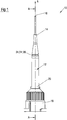
- Fig. 1 shows a perspective view of a first type of dispensing outlet 10.
- the dispensing outlet 10 comprises a housing 12 with a first end 14 of the housing 12 having a first outlet 16 and a second end 18 of the housing 12 having a mixing or reception space 20 formed therein.
- the first end 14 is oppositely disposed of the second end 18 along the longitudinal axis A of the dispensing outlet 10.
- the mixing or reception space 20 is configured to receive a further component, such as a cartridge 22, which is illustrated in Fig. 7 .
- a pre-determined breaking point 24 is formed at the housing 12 between the first outlet 16 and the mixing or reception space 20.
- the pre-determined breaking point 24 is formed in a wall 12' (see Fig. 2 ) of the housing 12 and peripherally extends around the housing 12 in the form of a groove 24'.
- the wall 12' of the housing 12 generally has a wall thickness which is larger than the wall thickness of the pre-determined breaking point 24.
- the pre-determined breaking point 24 can have a wall thickness selected at the thinnest point of the pre-determined breaking point 24 in the range of 5 to 60% of the wall thickness of the wall 12' of the housing 12 at the thickest point of the wall 12'.
- a wall thickness of the thinnest point of the pre-determined breaking point 24, i.e. a base of the groove 24', is selected such that the pre-determined breaking point 24 is configured to withstand internal pressures of up to 5bar, preferably 10 bar, more preferably of up to 15 bar before leaking.
- a simple bursting test can be performed, during which one end of the housing is blocked off and the pressure within the housing is increased up until the desired pressure is obtained. If the housing does not burst then the housing satisfies the above requirements. If the housing bursts then it does not satisfy the above requirements.
- the pre-determined breaking point 24, i.e. the groove 24' forming the pre-determined breaking point 24, has a V-shaped cross-section perpendicular to the longitudinal axis A, with a valley of the V facing towards the longitudinal axis A.
- Other types of cross-sections of the pre-determined breaking point 24 can be employed, such as a V-shaped cross-section with a base as shown in Fig. 5 , a U-shaped cross-section, or a L-shaped cross- section as shown in Fig. 6 .
- the dispensing outlet 10 comprises a second outlet 26 that is arranged at the position of the pre-determined breaking point 24 and that is set free on separating the first outlet 16 from the mixing or reception space 20 via the pre-determined breaking point 20.
- the second outlet 26 has an outlet opening 28 (see Fig. 2 ) with a larger diameter than an outlet opening 30 of the first outlet 16 (also shown in Fig. 2 ).
- the dispensing outlet 10 is a mixer 10', more specifically a static mixer 10', comprising said mixing space 20, with said mixing space 20 being configured to accommodate a mixing element 32.
- the pre-determined breaking point 24 is formed between the first outlet 16 and the mixing element 32.
- the first outlet 16 is formed by a cannula 34.
- the cannula 34 is more flexible than the housing 12 such that it can be bent away from the longitudinal axis A in use of the dispensing outlet 10. Furthermore, the cannula 34 is received in the first end 14 such that it is axially fixed in position, i.e. it cannot be moved to and fro along the longitudinal axis A, but is rotatable about the longitudinal axis A.
- the cannula 34 may be formed of a material different from that of the remainder of the housing 12, for example of metal. If a metal cannula 34 is selected then this has to be so thin walled that it can be bent while the housing 12 is not deformed.
- the cannula 34 may be formed from the same material as that of the housing 12.
- the housing 12 may be made from a plastic, especially a thermoplastic; an elastomer, in particular silicone; and/or a thermosetting resin.
- An internal diameter of the housing 12 at the pre-determined breaking point 24, i.e. the diameter of the outlet opening 26, is smaller than an internal diameter of that part of the housing 12 forming the mixing or reception space 20, i.e. the space configured to receive the mixing element 32 in Fig. 2 .
- the internal diameter of the housing 12 at the pre-determined breaking point 24 may be larger than an internal diameter of that part of the housing 12 forming the mixing or reception space or may be the same as an internal diameter of that part of the housing 12 forming the mixing or reception space 20.
- the second end 18 comprises a coupling section 38 via which the dispensing outlet 10 can be coupled to the cartridge 22.
- the coupling section 38 comprises an inlet section 40 via which multi-component material M, M' (see Fig. 7 ) can be guided to the mixer 10' from outlets (not shown) of said cartridge 22.
- the inlet section 40 comprises two inlets 42, 42' via which the multi-component material M, M' can be guided from the respective outlet of the cartridge 22 to the mixing element 32.
- the coupling section 38 further comprises a connecting part 44 comprising bayonet-like attachment means that are used to removeably attach the dispensing outlet 10 at the cartridge 22. This assembly is shown and discussed in more detail in connection with Fig. 7 .
- connecting parts 44 may also be used as are well known to the person skilled in the art, for example, the cartridge 22 may have a threaded portion (not shown) and the dispensing outlet 10 may be removeably attached to the cartridge 22 via a nut-like element (also not shown).
- an internal diameter of the housing 12 reduces in size between the pre-determined breaking point 24 and the first outlet 16.
- the internal diameter of the housing 12 reduces from a size of 100% at the pre-determined breaking point 24 to a size selected in the range of 1 to 30%, in particular 2 to 20 of the housing 12 at the first outlet 16.
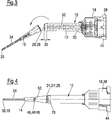
- Fig. 3 shows a sectional view of a second type of dispensing outlet 10 similar to the one shown in Figs. 1 and 2 in an activated state, i.e. a state in which the second outlet 26 is set free by separating the first outlet 16 from the housing 12 via the pre-determined breaking point 24.
- the difference between the dispensing outlet 10 of Figs. 1 & 2 and that shown in Fig. 3 is the different mixing element 32 used.
- mixing elements 32 there is no restriction on the type of mixing elements 32 that can be used with the dispensing outlet 10 described herein.
- a T-mixer mixing element 32 as shown in Fig. 1 and as sold by Sulzer Mixpac AG may be used, as can a helical shaped mixing element 32 also sold by Sulzer Mixpac AG.
- further types of mixing elements 32 that are available on the market can be used in conjunction with the dispensing outlet 10.
- a spacing 36 between the pre-determined breaking point 24 and an end of the static mixing element 32 is less than an outer diameter of the static mixing element 32 respectively of an inner diameter of the housing 12 surrounding the mixing or reception space 20.
- the spacing 36 is 1.9 mm.
- the spacing 36 is typically selected such that it corresponds to 30 to 95 % of the outer diameter of the static mixing element 10'.
- Fig. 4 shows a side view of a third type of dispensing outlet 10.
- the dispensing outlet 10 further comprises a second pre-determined breaking point 46 that is positioned between said pre-determined breaking point 24 and the first outlet 16.
- the second pre-determined breaking point 46 forms a third outlet 48 that is arranged at the position of the second pre-determined breaking point 46 and that is set free on separating the first outlet 16 from the housing 12 via the second pre-determined breaking point 46. It should be noted in this connection that the second pre-determined breaking point 46 can be configured in an analogous way to the first pre-determined breaking point 24, i.e can also be formed as a peripherally extending groove 46'.
- the third outlet 48 has an outlet opening 50 having a larger diameter than that of the first outlet 16, but smaller than that of the second outlet 26.
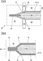
- Fig. 5 shows a schematic sectional view of a first type of injection mold 60 for forming the dispensing outlet 10 as described herein.
- the injection mold has respective inputs for the components to be injected (not shown) and for any required vacuum apparatus (also not shown).
- inserts 60', 60", 60"' specific to the shape of the dispensing outlet 10 are also introduced into the injection mold 60.
- the injection mold 60 comprises an internal space 62, the internal space is configured as a negative mold for the housing of the dispensing outlet 10, i.e. it is configured to resemble the internal and external shape of the housing 12.
- a shape of the internal space 62 is defined by the outer shape of the respective inserts 60', 60", 60" and 68 (see Fig. 6 ) respectively used to form the desired dispensing outlet 10.
- shutter elements 64 are moveably arranged in the injection mold 60.
- the shutter elements 64 comprise projections that project into the internal space 62 and form a negative shape of the pre-determined breaking point 24, i.e. of the groove 24'.
- the pre-determined breaking point 24 to be formed has a V-shaped cross-section with a base 66.
- the cannula 34 forms part of the mold 60 and the housing 12 is injection molded around the cannula 34.
- Fig. 6 shows a further schematic sectional view through a second type of injection mold 60 for forming the dispensing outlet 10.
- the internal space 62 comprises an internal surface 70, with a projection 72 projecting from the internal surface 70 and into the injection mold 60.
- the projection 72 is shaped such that it reflects a negative shape of the pre-determined breaking point 24 that is to be formed in the injection mold 60. In the present instance a L-shaped pre-determined breaking point 24.
- a molten form of the material forming the housing 12 and optionally that of the cannula 34 is injected into the internal space 62 of the injection mold 60 to integrally form the pre-determined breaking point 24 at the housing 12 of the dispensing outlet 10.
- Fig. 7 shows a schematic side view of a dispensing system 100.
- the dispensing system 100 comprises a two-component cartridge 22, with each of the cartridges thereof being filled with respective material M, M' that is to be mixed by the mixing element 32 in the dispensing outlet 10.
- the dispensing outlet 10 is attached to the cartridge 22 via the coupling section 38 and specifically via the connecting part 44 that cooperates with connecting members 102 present at the cartridge 22 and additionally through the interaction between the inlets 42, 42' into the coupling section 38 of the dispensing outlet 10 and the outlets from the cartridge 22.
- the cartridge 22 and dispensing outlet 10 are typically inserted into a dispenser (not shown).
- the user of the dispensing system decides which outlet size is required for the desired application. On choosing the desired application the user then proceeds to either use the first outlet 16 or to use either of the second and third outlets 26, 46 by separating the first outlet 16 from the housing 12 via the respective pre-determined breaking point 24, 46.
- the dispenser is then used to dispense the multi-component material M, M'.
- the multi-component material M, M' is then discharged from the dispensing system via the respective outlet 16, 26, 48.
Landscapes
- Health & Medical Sciences (AREA)
- Life Sciences & Earth Sciences (AREA)
- Animal Behavior & Ethology (AREA)
- General Health & Medical Sciences (AREA)
- Public Health (AREA)
- Veterinary Medicine (AREA)
- Oral & Maxillofacial Surgery (AREA)
- Dentistry (AREA)
- Epidemiology (AREA)
- Chemical & Material Sciences (AREA)
- Engineering & Computer Science (AREA)
- Chemical Kinetics & Catalysis (AREA)
- Mechanical Engineering (AREA)
- Biomedical Technology (AREA)
- Heart & Thoracic Surgery (AREA)
- Hematology (AREA)
- Anesthesiology (AREA)
- Vascular Medicine (AREA)
- Dispersion Chemistry (AREA)
- Injection Moulding Of Plastics Or The Like (AREA)
Priority Applications (8)
| Application Number | Priority Date | Filing Date | Title |
|---|---|---|---|
| EP18196737.3A EP3628353A1 (fr) | 2018-09-26 | 2018-09-26 | Sortie de distributeur, système d'un distributeur, méthode pour utiliser un système d'un distributeur, moules d'injection et méthode pour produire la sortie de distributeur |
| KR1020217008651A KR102638160B1 (ko) | 2018-09-26 | 2019-09-20 | 분배 출구, 분배 시스템, 분배 시스템 사용 방법, 사출 금형 및 분배 출구 제조 방법 |
| JP2021516942A JP7354234B2 (ja) | 2018-09-26 | 2019-09-20 | ディスペンシング・アウトレット、ディスペンシング・システム、ディスペンシング・システムを使用する方法、射出成形金型、および、ディスペンシング・アウトレットを作り出す方法 |
| BR112021005497-9A BR112021005497B1 (pt) | 2018-09-26 | 2019-09-20 | Saída de dispensação, sistema de dispensação, método de uso de um sistema de dispensação, molde de injeção e método de produção de uma saída de dispensação |
| PCT/EP2019/075293 WO2020064532A1 (fr) | 2018-09-26 | 2019-09-20 | Sortie de distribution, système de distribution, procédé d'utilisation de système de distribution, moule d'injection et procédé de fabrication de sortie de distribution |
| US17/276,551 US12083328B2 (en) | 2018-09-26 | 2019-09-20 | Dispensing outlet, dispensing system, method of using a dispensing system, injection mold and method of producing a dispensing outlet |
| CN201980062931.5A CN112739400A (zh) | 2018-09-26 | 2019-09-20 | 施配出口、施配系统、使用施配系统的方法、注射模具以及生产施配出口的方法 |
| EP19769516.6A EP3826704A1 (fr) | 2018-09-26 | 2019-09-20 | Sortie de distribution, système de distribution, procédé d'utilisation de système de distribution, moule d'injection et procédé de fabrication de sortie de distribution |
Applications Claiming Priority (1)
| Application Number | Priority Date | Filing Date | Title |
|---|---|---|---|
| EP18196737.3A EP3628353A1 (fr) | 2018-09-26 | 2018-09-26 | Sortie de distributeur, système d'un distributeur, méthode pour utiliser un système d'un distributeur, moules d'injection et méthode pour produire la sortie de distributeur |
Publications (1)
| Publication Number | Publication Date |
|---|---|
| EP3628353A1 true EP3628353A1 (fr) | 2020-04-01 |
Family
ID=63685630
Family Applications (1)
| Application Number | Title | Priority Date | Filing Date |
|---|---|---|---|
| EP18196737.3A Withdrawn EP3628353A1 (fr) | 2018-09-26 | 2018-09-26 | Sortie de distributeur, système d'un distributeur, méthode pour utiliser un système d'un distributeur, moules d'injection et méthode pour produire la sortie de distributeur |
Country Status (1)
| Country | Link |
|---|---|
| EP (1) | EP3628353A1 (fr) |
Cited By (1)
| Publication number | Priority date | Publication date | Assignee | Title |
|---|---|---|---|---|
| US20220022998A1 (en) * | 2018-12-03 | 2022-01-27 | 3M Innovative Properties Company | Dispensing Device for Dental Retraction Material |
Citations (3)
| Publication number | Priority date | Publication date | Assignee | Title |
|---|---|---|---|---|
| US20110273956A1 (en) * | 2009-03-11 | 2011-11-10 | Sasan Habibi-Naini | Device for dispensing a filling mass |
| GB2512123A (en) * | 2013-03-21 | 2014-09-24 | Loft Storage Stilts Ltd | Nozzle |
| US20180221912A1 (en) * | 2012-03-22 | 2018-08-09 | DFund Limited | Flow restrictor |
-
2018
- 2018-09-26 EP EP18196737.3A patent/EP3628353A1/fr not_active Withdrawn
Patent Citations (3)
| Publication number | Priority date | Publication date | Assignee | Title |
|---|---|---|---|---|
| US20110273956A1 (en) * | 2009-03-11 | 2011-11-10 | Sasan Habibi-Naini | Device for dispensing a filling mass |
| US20180221912A1 (en) * | 2012-03-22 | 2018-08-09 | DFund Limited | Flow restrictor |
| GB2512123A (en) * | 2013-03-21 | 2014-09-24 | Loft Storage Stilts Ltd | Nozzle |
Cited By (1)
| Publication number | Priority date | Publication date | Assignee | Title |
|---|---|---|---|---|
| US20220022998A1 (en) * | 2018-12-03 | 2022-01-27 | 3M Innovative Properties Company | Dispensing Device for Dental Retraction Material |
Similar Documents
| Publication | Publication Date | Title |
|---|---|---|
| CN101400315B (zh) | 材料分配器件 | |
| CN102387871B (zh) | 用于排出填充物的装置 | |
| AU2012325253B2 (en) | Cartridge, method for producing said cartridge, and multi-component cartridge | |
| EP3171813B1 (fr) | Récipient de stockage et de distribution d'un liquide | |
| EP3313560B1 (fr) | Mélangeur statique, procédé d'assemblage d'un tel mélangeur et appareil de distribution | |
| US12083328B2 (en) | Dispensing outlet, dispensing system, method of using a dispensing system, injection mold and method of producing a dispensing outlet | |
| EP3628353A1 (fr) | Sortie de distributeur, système d'un distributeur, méthode pour utiliser un système d'un distributeur, moules d'injection et méthode pour produire la sortie de distributeur | |
| BR112021005497B1 (pt) | Saída de dispensação, sistema de dispensação, método de uso de um sistema de dispensação, molde de injeção e método de produção de uma saída de dispensação | |
| US20220080374A1 (en) | Outlet for a static mixer | |
| EP4670669A2 (fr) | Récipient-capsule dentaire |
Legal Events
| Date | Code | Title | Description |
|---|---|---|---|
| PUAI | Public reference made under article 153(3) epc to a published international application that has entered the european phase |
Free format text: ORIGINAL CODE: 0009012 |
|
| STAA | Information on the status of an ep patent application or granted ep patent |
Free format text: STATUS: THE APPLICATION HAS BEEN PUBLISHED |
|
| AK | Designated contracting states |
Kind code of ref document: A1 Designated state(s): AL AT BE BG CH CY CZ DE DK EE ES FI FR GB GR HR HU IE IS IT LI LT LU LV MC MK MT NL NO PL PT RO RS SE SI SK SM TR |
|
| AX | Request for extension of the european patent |
Extension state: BA ME |
|
| STAA | Information on the status of an ep patent application or granted ep patent |
Free format text: STATUS: THE APPLICATION IS DEEMED TO BE WITHDRAWN |
|
| 18D | Application deemed to be withdrawn |
Effective date: 20201002 |