EP3628440A1 - Dispositif de positionnement - Google Patents
Dispositif de positionnement Download PDFInfo
- Publication number
- EP3628440A1 EP3628440A1 EP18197206.8A EP18197206A EP3628440A1 EP 3628440 A1 EP3628440 A1 EP 3628440A1 EP 18197206 A EP18197206 A EP 18197206A EP 3628440 A1 EP3628440 A1 EP 3628440A1
- Authority
- EP
- European Patent Office
- Prior art keywords
- positioning device
- pin
- retaining ring
- locating
- base body
- Prior art date
- Legal status (The legal status is an assumption and is not a legal conclusion. Google has not performed a legal analysis and makes no representation as to the accuracy of the status listed.)
- Granted
Links
Images




Classifications
-
- B—PERFORMING OPERATIONS; TRANSPORTING
- B23—MACHINE TOOLS; METAL-WORKING NOT OTHERWISE PROVIDED FOR
- B23Q—DETAILS, COMPONENTS, OR ACCESSORIES FOR MACHINE TOOLS, e.g. ARRANGEMENTS FOR COPYING OR CONTROLLING; MACHINE TOOLS IN GENERAL CHARACTERISED BY THE CONSTRUCTION OF PARTICULAR DETAILS OR COMPONENTS; COMBINATIONS OR ASSOCIATIONS OF METAL-WORKING MACHINES, NOT DIRECTED TO A PARTICULAR RESULT
- B23Q3/00—Devices holding, supporting, or positioning work or tools, of a kind normally removable from the machine
- B23Q3/18—Devices holding, supporting, or positioning work or tools, of a kind normally removable from the machine for positioning only
-
- B—PERFORMING OPERATIONS; TRANSPORTING
- B23—MACHINE TOOLS; METAL-WORKING NOT OTHERWISE PROVIDED FOR
- B23Q—DETAILS, COMPONENTS, OR ACCESSORIES FOR MACHINE TOOLS, e.g. ARRANGEMENTS FOR COPYING OR CONTROLLING; MACHINE TOOLS IN GENERAL CHARACTERISED BY THE CONSTRUCTION OF PARTICULAR DETAILS OR COMPONENTS; COMBINATIONS OR ASSOCIATIONS OF METAL-WORKING MACHINES, NOT DIRECTED TO A PARTICULAR RESULT
- B23Q3/00—Devices holding, supporting, or positioning work or tools, of a kind normally removable from the machine
- B23Q3/18—Devices holding, supporting, or positioning work or tools, of a kind normally removable from the machine for positioning only
- B23Q3/183—Centering devices
-
- B—PERFORMING OPERATIONS; TRANSPORTING
- B23—MACHINE TOOLS; METAL-WORKING NOT OTHERWISE PROVIDED FOR
- B23Q—DETAILS, COMPONENTS, OR ACCESSORIES FOR MACHINE TOOLS, e.g. ARRANGEMENTS FOR COPYING OR CONTROLLING; MACHINE TOOLS IN GENERAL CHARACTERISED BY THE CONSTRUCTION OF PARTICULAR DETAILS OR COMPONENTS; COMBINATIONS OR ASSOCIATIONS OF METAL-WORKING MACHINES, NOT DIRECTED TO A PARTICULAR RESULT
- B23Q3/00—Devices holding, supporting, or positioning work or tools, of a kind normally removable from the machine
- B23Q3/005—Guides for workpieces
-
- B—PERFORMING OPERATIONS; TRANSPORTING
- B62—LAND VEHICLES FOR TRAVELLING OTHERWISE THAN ON RAILS
- B62D—MOTOR VEHICLES; TRAILERS
- B62D65/00—Designing, manufacturing, e.g. assembling, facilitating disassembly, or structurally modifying motor vehicles or trailers, not otherwise provided for
- B62D65/02—Joining sub-units or components to, or positioning sub-units or components with respect to, body shell or other sub-units or components
- B62D65/024—Positioning of sub-units or components with respect to body shell or other sub-units or components
- B62D65/026—Positioning of sub-units or components with respect to body shell or other sub-units or components by using a jig or the like; Positioning of the jig
Definitions
- the present invention relates to a positioning device for positioning a body component with at least one mounting hole in vehicle construction.
- thin-walled components In automotive engineering, especially in the course of body construction, thin-walled components, mostly sheet metal parts, often have to be positioned exactly, in particular in order to be welded or otherwise joined to other body components or body groups.
- the thin-walled components have at least one, but usually at least two receiving bores. Locating bolts on a positioning device are used to reach through these bores in the body parts and to position the components to be connected to one another.
- the locating bolts often have a conical end in order to get into the bores more easily and to center the components when the locating bolts pass through, therefore such locating bolts are also called “centering bolts”.
- the DE 39 19 077 C1 discloses, for example, a device for position-defined clamping of a workpiece on a processing table with a workpiece holder on which the workpiece can be detached is attached and which is provided with centering holes which cooperate with correspondingly arranged on the machining table, above this protruding centering pin, a first group of centering holes and centering pin is provided which determine the position of the workpiece holder in the X and Y directions.
- the EP 0 911 112 A1 discloses a pressure-actuated combined centering and tensioning device, in particular for use in the bodywork of the motor vehicle industry, with a bolt-shaped centering part and a tensioning part, the centering part and the tensioning part alternately in two directions - exciting and centering or releasing - being driven in succession by pressure medium pressure and that Clamping part is mounted in and on the bolt-shaped centering part.
- the mounting holes in the body parts are sometimes later, at least after the positioning of the components, provided with sealing plugs to close these openings.
- an improved positioning device for positioning a body component with at least one receiving bore in vehicle construction, to be specified, which in particular prevents damage to the body components in the area of the receiving bores during the positioning.
- a positioning device for positioning a body component with at least one mounting hole in vehicle construction comprising a mounting bolt with a conical end which is designed to be guided axially through the mounting hole of the body component in order to center and position the body component.
- the locating pin being mounted in a radially floating manner.
- a locating pin with a conical end for centering and positioning a component is supported in a radially floating manner. It has been shown that the mounting bores of the positioned components are more severely damaged by a rigid design of a mounting bolt. Particularly when the components are received several times in the course of vehicle assembly, the mounting holes are increasingly widened and / or damaged when rigid mounting bolts are used. The result is greater dimensional inaccuracies or leaks in the body components. Due to the radially floating mounting of the locating bolts, the body components can be positioned exactly, if necessary also positioned several times, and are damaged less or not at all.
- the word “bore” does not determine the method of manufacture of the corresponding opening and is therefore to be understood in the sense of an opening leading through the component with a usually round cross section.
- the locating pin preferably has a cylindrical pin section and is mounted in a retaining ring in a radially floating manner.
- the retaining ring has a slightly larger inner diameter than the outer diameter of the cylindrical bolt section. There is therefore a "play" between the retaining ring and the locating bolt or the cylindrical bolt section of the locating bolt.
- the locating bolt is of two-stage design and has a cylindrical collar in addition to the cylindrical bolt section, the cylindrical collar having a larger diameter than the cylindrical bolt section.
- the retaining ring is also formed in two stages and the locating pin is radially floating in two stages in this retaining ring.
- a first step of the retaining ring has a larger inside diameter than the outside diameter of the cylindrical bolt section and a second step of the retaining ring has a larger inside diameter than the outside diameter of the cylindrical collar. So there is a "play" between the first stage of the retaining ring and locating pin and also between the second stage of the retaining ring and the outer diameter of the cylindrical collar.
- the positioning device preferably comprises a base body, the retaining ring being fastened to the base body or being formed in one piece with the base body, the locating bolt being fixed axially by the base body and / or by the retaining ring.
- the locating pin can essentially, at least axially, but preferably also radially apart from the degrees of freedom due to the floating bearing, be moved and positioned together with the base body.
- the receiving bolt preferably has a recess in the form of an inner cone at its end opposite the conical end.
- the inner cone extends axially at this end of the locating pin into the interior of the locating pin and preferably coaxially with the locating pin, about a central axis common to the locating pin.
- the positioning device preferably comprises a locking pin, the locking pin having a conical end, the locking pin being axially displaceable relative to the locating pin.
- the locking pin can therefore be moved towards the mounting pin, in particular so that the locking pin comes into contact with the mounting pin.
- the diameters of the inner cone of the locating bolt and the conical end of the locking bolt preferably match one another, so that the conical end can be accommodated in the inner cone by a fit.
- This geometry of the two cones essentially also determines the possible "play” or the floating mounting between the locating pin and the attached collar on the one hand and the inside diameter of the retaining ring on the other hand and can therefore be used to provide a desired play. If, for example, the diameter of the inner cone of the locating pin is smaller, the "play" is also smaller or the radially floating movement of the locating pin is smaller.
- the locking pin can be guided through a bore in the base body and the locking pin can be axially displaceable relative to the base body, thus being displaced in the bore of the base body.
- the locking pin is preferably mounted radially in the base body by means of two bearing bushes, in particular in the bore of the base body.
- the locking pin can preferably be displaced axially with respect to the locating pin and with respect to the base body by means of a pneumatic cylinder.
- the pneumatic cylinder can be attached to the base body.
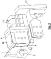
- Fig. 1-6 is a positioning device according to the invention for positioning a body component 1 with a receiving bore (see Figs. 3 - 5 ), which comprises a locating pin 2 with a conical end 3, which is designed to be guided axially through the locating bore of the body component 1 in order to center and position the body component 1.
- the locating pin 2 is supported in a radially floating manner in a retaining ring 4.
- the locating pin 2 has a cylindrical pin section which has a smaller outside diameter than the inside diameter of the retaining ring 4.
- the locating pin 2 is of at least two stages and, in addition to the cylindrical pin section, has a cylindrical collar 5, the cylindrical collar 5 having a larger diameter than the cylindrical pin section.
- the retaining ring 4 is also formed in two stages and the locating pin 2 is mounted in the retaining ring 4 in a radially floating manner in two stages.
- a first step of the retaining ring 4 has a larger inner diameter than the outer diameter of the cylindrical bolt section and a second step of the holding ring 4 has a larger inner diameter than the outer diameter of the cylindrical collar 5. So there is, as in Fig. 2 clearly visible, a game 18 between the first stage of the retaining ring 4 and the locating pin 2 and also between the second stage of the retaining ring 4 and the outer diameter of the cylindrical collar 5.
- the positioning device comprises a base body 6, the retaining ring 4 being fastened to the base body 6.
- the locating pin 2 is axially supported by the base body 6 and by the retaining ring 4, as in FIG Fig. 2 well visible.
- the receiving bolt 2 has at its end opposite the conical end 3 an axial recess in the form of an inner cone 7.
- the positioning device comprises a locking pin 8, the locking pin 8 having a conical end 9.
- the locking pin 8 is axially displaceable relative to the locating pin 2.
- the diameters of the inner cone 7 of the locating bolt 2 and of the conical end 9 of the locking bolt 8 match each other, so that the conical end 9 can be received in the inner cone 7 in contact.
- the locking pin 8 is guided through a bore in the base body 6 and axially displaceable relative to the base body 6.
- the locking pin 8 is mounted radially in the base body 6 by means of two bearing bushes 10.
- the bearing bushes 10 are arranged in the bore of the base body 6.
- the locking pin 8 can be moved axially relative to the locating pin 2 and relative to the base body 6.
- the pneumatic cylinder 11 is laterally attached to the base body 6 or a connection plate connected to the base body 6.
- the mounting bolt 2 with the corresponding diameter for the component 1 to be accommodated or its mounting bore is thus placed on the front of the base body 6 in a floating manner.
- the locating pin 2 has an attached collar 5 at the rear end and additionally an inner cone 7 at this end.
- the locating pin 2 is fastened in a radially floating manner with a retaining ring 4 screwed on at the front.
- the stepped bore of the front retaining ring 4 is larger in diameter to the locating pin 2 and to the attached collar 5 of the locating pin 2, as required.
- the width of the collar 5 from the mounting bolt 2 is minimally smaller than the inner width of the retaining ring 4.
- the mounting pin 2 can move freely radially in all directions.
- a locking pin 8 with a cone 9 attached at the front is installed in the base body 6, which is guided via bearing bushes 10.
- the cone angle corresponds to the inner cone 7 of the locating bolt 2.
- This locking pin 8 is pushed forwards or backwards by means of the pneumatic cylinder 11 placed on the back (in the direction of the in FIG Fig. 1 arrows).
- the picked-up component 1 is also brought into the correct position via the mounting pin 2. This is followed by further clamping steps for component 1.
- the positioning device can use the two inductive proximity switches, sensors 15 attached at the top of the base body 6, to sense the position of the metal indicator 14 and thus the locking pin 8 and the mounting pin 2 in order to provide a system control process with feedback about the position to be able to give the locating pin 2 (so-called INI query).
- the sensors 15 are protected by a cover 16 as a dirt cover cap and can be integrated into the control of the system in various systems.
- a dirt cover cap 13 with a sealing ring 12 is pressed on to the front of the mounting pin 2 to prevent the positioning device from becoming dirty.
- the dirt cover cap 13 therefore moves with the locating pin 2 and covers the "play" between the locating pin 2 and the retaining ring 4 - as protection against contamination. Therefore also in Fig. 6 no "game” visible.
- the dirt cap 13 thus moves with the locating pin 2 relative to the retaining ring 4 - for example, the dirt cap 13 slides on the (front) surface of the retaining ring 4 or a seal or a sliding ring is arranged in between.
- the stepped bore of the front retaining ring 4 is larger in diameter to the locating pin 2 and to the collar 5 of the locating pin 2, as required, in diameter.
- threaded bores and fitting bores for fastening in a device are made on the side and at the bottom (see Fig. 3 ).
- a positioning device can be used, for example, on so-called framer gates for side frames with mounting holes in body construction, or on robot-guided gripper frames for components with mounting holes in body construction and for a wide variety of thin-walled components with mounting holes that should not be damaged, and whose mounting holes are particularly provided with sealing plugs .
Landscapes
- Engineering & Computer Science (AREA)
- Mechanical Engineering (AREA)
- Insertion Pins And Rivets (AREA)
- Jigs For Machine Tools (AREA)
Priority Applications (2)
| Application Number | Priority Date | Filing Date | Title |
|---|---|---|---|
| EP18197206.8A EP3628440B1 (fr) | 2018-09-27 | 2018-09-27 | Dispositif de positionnement |
| US16/560,038 US11198201B2 (en) | 2018-09-27 | 2019-09-04 | Positioning device |
Applications Claiming Priority (1)
| Application Number | Priority Date | Filing Date | Title |
|---|---|---|---|
| EP18197206.8A EP3628440B1 (fr) | 2018-09-27 | 2018-09-27 | Dispositif de positionnement |
Publications (2)
| Publication Number | Publication Date |
|---|---|
| EP3628440A1 true EP3628440A1 (fr) | 2020-04-01 |
| EP3628440B1 EP3628440B1 (fr) | 2022-03-16 |
Family
ID=63708103
Family Applications (1)
| Application Number | Title | Priority Date | Filing Date |
|---|---|---|---|
| EP18197206.8A Active EP3628440B1 (fr) | 2018-09-27 | 2018-09-27 | Dispositif de positionnement |
Country Status (2)
| Country | Link |
|---|---|
| US (1) | US11198201B2 (fr) |
| EP (1) | EP3628440B1 (fr) |
Families Citing this family (4)
| Publication number | Priority date | Publication date | Assignee | Title |
|---|---|---|---|---|
| US12023773B1 (en) * | 2020-08-13 | 2024-07-02 | E&E Custom Products, Llc | Floating shot pin assembly and method |
| CN113001435B (zh) * | 2021-02-22 | 2022-09-23 | 航天科工空间工程发展有限公司 | 一种定位系统、承载装置及定位装置 |
| EP4206011B1 (fr) * | 2022-01-04 | 2025-09-17 | Ningbo Geely Automobile Research & Development Co., Ltd. | Outil de réglage de porte |
| CN115008230A (zh) * | 2022-06-24 | 2022-09-06 | 上汽通用五菱汽车股份有限公司 | 一种浮动定位夹紧机构 |
Citations (5)
| Publication number | Priority date | Publication date | Assignee | Title |
|---|---|---|---|---|
| DE3919077C1 (fr) | 1989-06-10 | 1990-07-26 | Erowa Ag, Reinach, Ch | |
| EP0911112A1 (fr) | 1997-10-21 | 1999-04-28 | TÜNKERS MASCHINENBAU GmbH | Dispositif combiné de centrage et serrage actionnable par fluide sous pression, utilisable en particulier pour la construction de carrosseries automobile dans l'industrie automobile |
| WO2004004977A2 (fr) * | 2002-07-10 | 2004-01-15 | Welker Bearing Company | Ensemble de positionnement equipe d'un doigt d'ablocage extensible |
| DE202016101411U1 (de) * | 2016-03-14 | 2017-06-19 | Schunk Gmbh & Co. Kg Spann- Und Greiftechnik | Einzugsspannelement, insbesondere Einzugsspannbolzen oder Einzugsspannring, und zugehöriges Spannsystem |
| DE102016122090A1 (de) * | 2016-11-17 | 2018-05-17 | Frank Nickl | Spannsystem |
Family Cites Families (1)
| Publication number | Priority date | Publication date | Assignee | Title |
|---|---|---|---|---|
| US7156385B2 (en) * | 2003-06-03 | 2007-01-02 | Norgren Automotive, Inc. | Linearly adjustable apparatus for locating a workpiece |
-
2018
- 2018-09-27 EP EP18197206.8A patent/EP3628440B1/fr active Active
-
2019
- 2019-09-04 US US16/560,038 patent/US11198201B2/en active Active
Patent Citations (5)
| Publication number | Priority date | Publication date | Assignee | Title |
|---|---|---|---|---|
| DE3919077C1 (fr) | 1989-06-10 | 1990-07-26 | Erowa Ag, Reinach, Ch | |
| EP0911112A1 (fr) | 1997-10-21 | 1999-04-28 | TÜNKERS MASCHINENBAU GmbH | Dispositif combiné de centrage et serrage actionnable par fluide sous pression, utilisable en particulier pour la construction de carrosseries automobile dans l'industrie automobile |
| WO2004004977A2 (fr) * | 2002-07-10 | 2004-01-15 | Welker Bearing Company | Ensemble de positionnement equipe d'un doigt d'ablocage extensible |
| DE202016101411U1 (de) * | 2016-03-14 | 2017-06-19 | Schunk Gmbh & Co. Kg Spann- Und Greiftechnik | Einzugsspannelement, insbesondere Einzugsspannbolzen oder Einzugsspannring, und zugehöriges Spannsystem |
| DE102016122090A1 (de) * | 2016-11-17 | 2018-05-17 | Frank Nickl | Spannsystem |
Also Published As
| Publication number | Publication date |
|---|---|
| EP3628440B1 (fr) | 2022-03-16 |
| US20200101572A1 (en) | 2020-04-02 |
| US11198201B2 (en) | 2021-12-14 |
Similar Documents
| Publication | Publication Date | Title |
|---|---|---|
| EP2720907B1 (fr) | Dispositif de fixation comprenant un compensateur de tolérance | |
| DE112008004188B4 (de) | Befestigungsstruktur mit einer Durchgangstülle | |
| EP1869334B1 (fr) | Palier lisse, systeme de palier lisse et montage d'un systeme de palier lisse | |
| EP3628440B1 (fr) | Dispositif de positionnement | |
| DE102019111422A1 (de) | Nabenabdeckung für eine Reifenbefüllvorrichtung eines Fahrzeugs | |
| DE102013208635B4 (de) | Ausgleichsvorrichtung | |
| DE102016206864A1 (de) | Kugelgelenk, insbesondere für ein Fahrwerk eines Kraftfahrzeugs, sowie Verfahren zur Montage eines solchen Kugelgelenks | |
| DE102005009721B3 (de) | Lageranordnung | |
| DE69215493T2 (de) | Haltevorrichtung mit entfernbarer Zentrierbüchse | |
| EP3110587B1 (fr) | Système de fixation destiné à une panne | |
| EP0854076B1 (fr) | Procédé et dispositif pour presser la cartouche préassemblée d'un joint à rotule dans le palier d'un arbre de direction | |
| DE102015211419A1 (de) | Anordnung zur Abdichtung eines Aktuators und Adapterring zur Abdichtung | |
| EP1187995B1 (fr) | Assemblage par aboutement et procede permettant de le realiser et colonne de direction pour automobiles munie d'un tel assemblage par aboutement | |
| EP1503114B1 (fr) | Assemblage d'une tige de piston au piston | |
| DE102016123364A1 (de) | Klemmvorrichtung und Verfahren zur Herstellung von Klemmvorrichtungen | |
| EP3344431B1 (fr) | Unité à fluide sous pression comportant un boîtier en plastique fabriqué par moulage par injection et procédé pour sa fabrication | |
| EP3966057B1 (fr) | Palier de groupe motopropulseur dans un véhicule | |
| EP0600227B1 (fr) | Charnière à rotule pour portières de voitures | |
| DE19734785C2 (de) | Selbstkalibrierendes Verbindungselement für Verstelleinrichtungen in Kraftfahrzeugen | |
| DE3425158C2 (fr) | ||
| DE102005035857B4 (de) | Druckzylinder | |
| AT402656B (de) | Hydraulischer arbeitszylinder hydraulischer arbeitszylinder | |
| EP1391619B1 (fr) | Joint à rotule | |
| DE102017116255A1 (de) | Gewindemutter für einen Kugelgewindetrieb | |
| EP3574813B1 (fr) | Charnière pour un ensemble d'un siège de toilettes |
Legal Events
| Date | Code | Title | Description |
|---|---|---|---|
| PUAI | Public reference made under article 153(3) epc to a published international application that has entered the european phase |
Free format text: ORIGINAL CODE: 0009012 |
|
| STAA | Information on the status of an ep patent application or granted ep patent |
Free format text: STATUS: THE APPLICATION HAS BEEN PUBLISHED |
|
| AK | Designated contracting states |
Kind code of ref document: A1 Designated state(s): AL AT BE BG CH CY CZ DE DK EE ES FI FR GB GR HR HU IE IS IT LI LT LU LV MC MK MT NL NO PL PT RO RS SE SI SK SM TR |
|
| AX | Request for extension of the european patent |
Extension state: BA ME |
|
| STAA | Information on the status of an ep patent application or granted ep patent |
Free format text: STATUS: REQUEST FOR EXAMINATION WAS MADE |
|
| 17P | Request for examination filed |
Effective date: 20200803 |
|
| RBV | Designated contracting states (corrected) |
Designated state(s): AL AT BE BG CH CY CZ DE DK EE ES FI FR GB GR HR HU IE IS IT LI LT LU LV MC MK MT NL NO PL PT RO RS SE SI SK SM TR |
|
| STAA | Information on the status of an ep patent application or granted ep patent |
Free format text: STATUS: EXAMINATION IS IN PROGRESS |
|
| 17Q | First examination report despatched |
Effective date: 20210621 |
|
| GRAP | Despatch of communication of intention to grant a patent |
Free format text: ORIGINAL CODE: EPIDOSNIGR1 |
|
| STAA | Information on the status of an ep patent application or granted ep patent |
Free format text: STATUS: GRANT OF PATENT IS INTENDED |
|
| RIC1 | Information provided on ipc code assigned before grant |
Ipc: B62D 65/02 20060101ALI20210915BHEP Ipc: B23Q 3/18 20060101AFI20210915BHEP |
|
| INTG | Intention to grant announced |
Effective date: 20211011 |
|
| GRAS | Grant fee paid |
Free format text: ORIGINAL CODE: EPIDOSNIGR3 |
|
| GRAA | (expected) grant |
Free format text: ORIGINAL CODE: 0009210 |
|
| STAA | Information on the status of an ep patent application or granted ep patent |
Free format text: STATUS: THE PATENT HAS BEEN GRANTED |
|
| AK | Designated contracting states |
Kind code of ref document: B1 Designated state(s): AL AT BE BG CH CY CZ DE DK EE ES FI FR GB GR HR HU IE IS IT LI LT LU LV MC MK MT NL NO PL PT RO RS SE SI SK SM TR |
|
| REG | Reference to a national code |
Ref country code: GB Ref legal event code: FG4D Free format text: NOT ENGLISH |
|
| REG | Reference to a national code |
Ref country code: CH Ref legal event code: EP Ref country code: DE Ref legal event code: R096 Ref document number: 502018009095 Country of ref document: DE |
|
| REG | Reference to a national code |
Ref country code: IE Ref legal event code: FG4D Free format text: LANGUAGE OF EP DOCUMENT: GERMAN |
|
| REG | Reference to a national code |
Ref country code: AT Ref legal event code: REF Ref document number: 1475543 Country of ref document: AT Kind code of ref document: T Effective date: 20220415 |
|
| REG | Reference to a national code |
Ref country code: LT Ref legal event code: MG9D |
|
| REG | Reference to a national code |
Ref country code: NL Ref legal event code: MP Effective date: 20220316 |
|
| PG25 | Lapsed in a contracting state [announced via postgrant information from national office to epo] |
Ref country code: SE Free format text: LAPSE BECAUSE OF FAILURE TO SUBMIT A TRANSLATION OF THE DESCRIPTION OR TO PAY THE FEE WITHIN THE PRESCRIBED TIME-LIMIT Effective date: 20220316 Ref country code: RS Free format text: LAPSE BECAUSE OF FAILURE TO SUBMIT A TRANSLATION OF THE DESCRIPTION OR TO PAY THE FEE WITHIN THE PRESCRIBED TIME-LIMIT Effective date: 20220316 Ref country code: NO Free format text: LAPSE BECAUSE OF FAILURE TO SUBMIT A TRANSLATION OF THE DESCRIPTION OR TO PAY THE FEE WITHIN THE PRESCRIBED TIME-LIMIT Effective date: 20220616 Ref country code: LT Free format text: LAPSE BECAUSE OF FAILURE TO SUBMIT A TRANSLATION OF THE DESCRIPTION OR TO PAY THE FEE WITHIN THE PRESCRIBED TIME-LIMIT Effective date: 20220316 Ref country code: HR Free format text: LAPSE BECAUSE OF FAILURE TO SUBMIT A TRANSLATION OF THE DESCRIPTION OR TO PAY THE FEE WITHIN THE PRESCRIBED TIME-LIMIT Effective date: 20220316 Ref country code: BG Free format text: LAPSE BECAUSE OF FAILURE TO SUBMIT A TRANSLATION OF THE DESCRIPTION OR TO PAY THE FEE WITHIN THE PRESCRIBED TIME-LIMIT Effective date: 20220616 |
|
| PG25 | Lapsed in a contracting state [announced via postgrant information from national office to epo] |
Ref country code: LV Free format text: LAPSE BECAUSE OF FAILURE TO SUBMIT A TRANSLATION OF THE DESCRIPTION OR TO PAY THE FEE WITHIN THE PRESCRIBED TIME-LIMIT Effective date: 20220316 Ref country code: GR Free format text: LAPSE BECAUSE OF FAILURE TO SUBMIT A TRANSLATION OF THE DESCRIPTION OR TO PAY THE FEE WITHIN THE PRESCRIBED TIME-LIMIT Effective date: 20220617 Ref country code: FI Free format text: LAPSE BECAUSE OF FAILURE TO SUBMIT A TRANSLATION OF THE DESCRIPTION OR TO PAY THE FEE WITHIN THE PRESCRIBED TIME-LIMIT Effective date: 20220316 |
|
| PG25 | Lapsed in a contracting state [announced via postgrant information from national office to epo] |
Ref country code: NL Free format text: LAPSE BECAUSE OF FAILURE TO SUBMIT A TRANSLATION OF THE DESCRIPTION OR TO PAY THE FEE WITHIN THE PRESCRIBED TIME-LIMIT Effective date: 20220316 |
|
| REG | Reference to a national code |
Ref country code: DE Ref legal event code: R081 Ref document number: 502018009095 Country of ref document: DE Owner name: MAGNA STEYR FAHRZEUGTECHNIK GMBH & CO KG, AT Free format text: FORMER OWNER: MAGNA STEYR FAHRZEUGTECHNIK AG & CO KG, GRAZ, AT |
|
| PG25 | Lapsed in a contracting state [announced via postgrant information from national office to epo] |
Ref country code: SM Free format text: LAPSE BECAUSE OF FAILURE TO SUBMIT A TRANSLATION OF THE DESCRIPTION OR TO PAY THE FEE WITHIN THE PRESCRIBED TIME-LIMIT Effective date: 20220316 Ref country code: SK Free format text: LAPSE BECAUSE OF FAILURE TO SUBMIT A TRANSLATION OF THE DESCRIPTION OR TO PAY THE FEE WITHIN THE PRESCRIBED TIME-LIMIT Effective date: 20220316 Ref country code: RO Free format text: LAPSE BECAUSE OF FAILURE TO SUBMIT A TRANSLATION OF THE DESCRIPTION OR TO PAY THE FEE WITHIN THE PRESCRIBED TIME-LIMIT Effective date: 20220316 Ref country code: PT Free format text: LAPSE BECAUSE OF FAILURE TO SUBMIT A TRANSLATION OF THE DESCRIPTION OR TO PAY THE FEE WITHIN THE PRESCRIBED TIME-LIMIT Effective date: 20220718 Ref country code: ES Free format text: LAPSE BECAUSE OF FAILURE TO SUBMIT A TRANSLATION OF THE DESCRIPTION OR TO PAY THE FEE WITHIN THE PRESCRIBED TIME-LIMIT Effective date: 20220316 Ref country code: EE Free format text: LAPSE BECAUSE OF FAILURE TO SUBMIT A TRANSLATION OF THE DESCRIPTION OR TO PAY THE FEE WITHIN THE PRESCRIBED TIME-LIMIT Effective date: 20220316 Ref country code: CZ Free format text: LAPSE BECAUSE OF FAILURE TO SUBMIT A TRANSLATION OF THE DESCRIPTION OR TO PAY THE FEE WITHIN THE PRESCRIBED TIME-LIMIT Effective date: 20220316 |
|
| PG25 | Lapsed in a contracting state [announced via postgrant information from national office to epo] |
Ref country code: PL Free format text: LAPSE BECAUSE OF FAILURE TO SUBMIT A TRANSLATION OF THE DESCRIPTION OR TO PAY THE FEE WITHIN THE PRESCRIBED TIME-LIMIT Effective date: 20220316 Ref country code: IS Free format text: LAPSE BECAUSE OF FAILURE TO SUBMIT A TRANSLATION OF THE DESCRIPTION OR TO PAY THE FEE WITHIN THE PRESCRIBED TIME-LIMIT Effective date: 20220716 Ref country code: AL Free format text: LAPSE BECAUSE OF FAILURE TO SUBMIT A TRANSLATION OF THE DESCRIPTION OR TO PAY THE FEE WITHIN THE PRESCRIBED TIME-LIMIT Effective date: 20220316 |
|
| REG | Reference to a national code |
Ref country code: DE Ref legal event code: R097 Ref document number: 502018009095 Country of ref document: DE |
|
| PLBE | No opposition filed within time limit |
Free format text: ORIGINAL CODE: 0009261 |
|
| STAA | Information on the status of an ep patent application or granted ep patent |
Free format text: STATUS: NO OPPOSITION FILED WITHIN TIME LIMIT |
|
| PG25 | Lapsed in a contracting state [announced via postgrant information from national office to epo] |
Ref country code: DK Free format text: LAPSE BECAUSE OF FAILURE TO SUBMIT A TRANSLATION OF THE DESCRIPTION OR TO PAY THE FEE WITHIN THE PRESCRIBED TIME-LIMIT Effective date: 20220316 |
|
| 26N | No opposition filed |
Effective date: 20221219 |
|
| PG25 | Lapsed in a contracting state [announced via postgrant information from national office to epo] |
Ref country code: SI Free format text: LAPSE BECAUSE OF FAILURE TO SUBMIT A TRANSLATION OF THE DESCRIPTION OR TO PAY THE FEE WITHIN THE PRESCRIBED TIME-LIMIT Effective date: 20220316 |
|
| PG25 | Lapsed in a contracting state [announced via postgrant information from national office to epo] |
Ref country code: MC Free format text: LAPSE BECAUSE OF FAILURE TO SUBMIT A TRANSLATION OF THE DESCRIPTION OR TO PAY THE FEE WITHIN THE PRESCRIBED TIME-LIMIT Effective date: 20220316 |
|
| REG | Reference to a national code |
Ref country code: CH Ref legal event code: PL |
|
| REG | Reference to a national code |
Ref country code: BE Ref legal event code: MM Effective date: 20220930 |
|
| PG25 | Lapsed in a contracting state [announced via postgrant information from national office to epo] |
Ref country code: LU Free format text: LAPSE BECAUSE OF NON-PAYMENT OF DUE FEES Effective date: 20220927 |
|
| PG25 | Lapsed in a contracting state [announced via postgrant information from national office to epo] |
Ref country code: LI Free format text: LAPSE BECAUSE OF NON-PAYMENT OF DUE FEES Effective date: 20220930 Ref country code: IT Free format text: LAPSE BECAUSE OF FAILURE TO SUBMIT A TRANSLATION OF THE DESCRIPTION OR TO PAY THE FEE WITHIN THE PRESCRIBED TIME-LIMIT Effective date: 20220316 Ref country code: IE Free format text: LAPSE BECAUSE OF NON-PAYMENT OF DUE FEES Effective date: 20220927 Ref country code: CH Free format text: LAPSE BECAUSE OF NON-PAYMENT OF DUE FEES Effective date: 20220930 |
|
| PG25 | Lapsed in a contracting state [announced via postgrant information from national office to epo] |
Ref country code: BE Free format text: LAPSE BECAUSE OF NON-PAYMENT OF DUE FEES Effective date: 20220930 |
|
| PG25 | Lapsed in a contracting state [announced via postgrant information from national office to epo] |
Ref country code: HU Free format text: LAPSE BECAUSE OF FAILURE TO SUBMIT A TRANSLATION OF THE DESCRIPTION OR TO PAY THE FEE WITHIN THE PRESCRIBED TIME-LIMIT; INVALID AB INITIO Effective date: 20180927 |
|
| PG25 | Lapsed in a contracting state [announced via postgrant information from national office to epo] |
Ref country code: CY Free format text: LAPSE BECAUSE OF FAILURE TO SUBMIT A TRANSLATION OF THE DESCRIPTION OR TO PAY THE FEE WITHIN THE PRESCRIBED TIME-LIMIT Effective date: 20220316 |
|
| PG25 | Lapsed in a contracting state [announced via postgrant information from national office to epo] |
Ref country code: MK Free format text: LAPSE BECAUSE OF FAILURE TO SUBMIT A TRANSLATION OF THE DESCRIPTION OR TO PAY THE FEE WITHIN THE PRESCRIBED TIME-LIMIT Effective date: 20220316 |
|
| PG25 | Lapsed in a contracting state [announced via postgrant information from national office to epo] |
Ref country code: TR Free format text: LAPSE BECAUSE OF FAILURE TO SUBMIT A TRANSLATION OF THE DESCRIPTION OR TO PAY THE FEE WITHIN THE PRESCRIBED TIME-LIMIT Effective date: 20220316 |
|
| PG25 | Lapsed in a contracting state [announced via postgrant information from national office to epo] |
Ref country code: MT Free format text: LAPSE BECAUSE OF FAILURE TO SUBMIT A TRANSLATION OF THE DESCRIPTION OR TO PAY THE FEE WITHIN THE PRESCRIBED TIME-LIMIT Effective date: 20220316 |
|
| REG | Reference to a national code |
Ref country code: AT Ref legal event code: MM01 Ref document number: 1475543 Country of ref document: AT Kind code of ref document: T Effective date: 20230927 |
|
| PG25 | Lapsed in a contracting state [announced via postgrant information from national office to epo] |
Ref country code: AT Free format text: LAPSE BECAUSE OF NON-PAYMENT OF DUE FEES Effective date: 20230927 |
|
| PG25 | Lapsed in a contracting state [announced via postgrant information from national office to epo] |
Ref country code: AT Free format text: LAPSE BECAUSE OF NON-PAYMENT OF DUE FEES Effective date: 20230927 |
|
| REG | Reference to a national code |
Ref country code: DE Ref legal event code: R082 Ref document number: 502018009095 Country of ref document: DE Representative=s name: EULER, MATTHIAS, DR., DE |
|
| PGFP | Annual fee paid to national office [announced via postgrant information from national office to epo] |
Ref country code: DE Payment date: 20250919 Year of fee payment: 8 |
|
| PGFP | Annual fee paid to national office [announced via postgrant information from national office to epo] |
Ref country code: GB Payment date: 20250919 Year of fee payment: 8 |
|
| PGFP | Annual fee paid to national office [announced via postgrant information from national office to epo] |
Ref country code: FR Payment date: 20250922 Year of fee payment: 8 |
|
| PGFP | Annual fee paid to national office [announced via postgrant information from national office to epo] |
Ref country code: AT Payment date: 20260410 Year of fee payment: 5 |