EP3628480A2 - Packaging apparatus for film inflation and method thereof - Google Patents
Packaging apparatus for film inflation and method thereof Download PDFInfo
- Publication number
- EP3628480A2 EP3628480A2 EP19190121.4A EP19190121A EP3628480A2 EP 3628480 A2 EP3628480 A2 EP 3628480A2 EP 19190121 A EP19190121 A EP 19190121A EP 3628480 A2 EP3628480 A2 EP 3628480A2
- Authority
- EP
- European Patent Office
- Prior art keywords
- roller
- film material
- sealing
- heating element
- protective member
- Prior art date
- Legal status (The legal status is an assumption and is not a legal conclusion. Google has not performed a legal analysis and makes no representation as to the accuracy of the status listed.)
- Pending
Links
Images









Classifications
-
- B—PERFORMING OPERATIONS; TRANSPORTING
- B31—MAKING ARTICLES OF PAPER, CARDBOARD OR MATERIAL WORKED IN A MANNER ANALOGOUS TO PAPER; WORKING PAPER, CARDBOARD OR MATERIAL WORKED IN A MANNER ANALOGOUS TO PAPER
- B31D—MAKING ARTICLES OF PAPER, CARDBOARD OR MATERIAL WORKED IN A MANNER ANALOGOUS TO PAPER, NOT PROVIDED FOR IN SUBCLASSES B31B OR B31C
- B31D5/00—Multiple-step processes for making three-dimensional [3D] articles
- B31D5/0039—Multiple-step processes for making three-dimensional [3D] articles for making dunnage or cushion pads
- B31D5/0073—Multiple-step processes for making three-dimensional [3D] articles for making dunnage or cushion pads including pillow forming
-
- B—PERFORMING OPERATIONS; TRANSPORTING
- B65—CONVEYING; PACKING; STORING; HANDLING THIN OR FILAMENTARY MATERIAL
- B65D—CONTAINERS FOR STORAGE OR TRANSPORT OF ARTICLES OR MATERIALS, e.g. BAGS, BARRELS, BOTTLES, BOXES, CANS, CARTONS, CRATES, DRUMS, JARS, TANKS, HOPPERS, FORWARDING CONTAINERS; ACCESSORIES, CLOSURES, OR FITTINGS THEREFOR; PACKAGING ELEMENTS; PACKAGES
- B65D81/00—Containers, packaging elements, or packages, for contents presenting particular transport or storage problems, or adapted to be used for non-packaging purposes after removal of contents
- B65D81/02—Containers, packaging elements, or packages, for contents presenting particular transport or storage problems, or adapted to be used for non-packaging purposes after removal of contents specially adapted to protect contents from mechanical damage
- B65D81/05—Containers, packaging elements, or packages, for contents presenting particular transport or storage problems, or adapted to be used for non-packaging purposes after removal of contents specially adapted to protect contents from mechanical damage maintaining contents at spaced relation from package walls, or from other contents
- B65D81/051—Containers, packaging elements, or packages, for contents presenting particular transport or storage problems, or adapted to be used for non-packaging purposes after removal of contents specially adapted to protect contents from mechanical damage maintaining contents at spaced relation from package walls, or from other contents using pillow-like elements filled with cushioning material, e.g. elastic foam, fabric
- B65D81/052—Containers, packaging elements, or packages, for contents presenting particular transport or storage problems, or adapted to be used for non-packaging purposes after removal of contents specially adapted to protect contents from mechanical damage maintaining contents at spaced relation from package walls, or from other contents using pillow-like elements filled with cushioning material, e.g. elastic foam, fabric filled with fluid, e.g. inflatable elements
-
- B—PERFORMING OPERATIONS; TRANSPORTING
- B29—WORKING OF PLASTICS; WORKING OF SUBSTANCES IN A PLASTIC STATE IN GENERAL
- B29C—SHAPING OR JOINING OF PLASTICS; SHAPING OF MATERIAL IN A PLASTIC STATE, NOT OTHERWISE PROVIDED FOR; AFTER-TREATMENT OF THE SHAPED PRODUCTS, e.g. REPAIRING
- B29C65/00—Joining or sealing of preformed parts, e.g. welding of plastics materials; Apparatus therefor
- B29C65/02—Joining or sealing of preformed parts, e.g. welding of plastics materials; Apparatus therefor by heating, with or without pressure
- B29C65/18—Joining or sealing of preformed parts, e.g. welding of plastics materials; Apparatus therefor by heating, with or without pressure using heated tools
- B29C65/22—Heated wire resistive ribbon, resistive band or resistive strip
- B29C65/221—Heated wire resistive ribbon, resistive band or resistive strip characterised by the type of heated wire, resistive ribbon, band or strip
- B29C65/224—Heated wire resistive ribbon, resistive band or resistive strip characterised by the type of heated wire, resistive ribbon, band or strip being a resistive ribbon, a resistive band or a resistive strip
-
- B—PERFORMING OPERATIONS; TRANSPORTING
- B29—WORKING OF PLASTICS; WORKING OF SUBSTANCES IN A PLASTIC STATE IN GENERAL
- B29C—SHAPING OR JOINING OF PLASTICS; SHAPING OF MATERIAL IN A PLASTIC STATE, NOT OTHERWISE PROVIDED FOR; AFTER-TREATMENT OF THE SHAPED PRODUCTS, e.g. REPAIRING
- B29C65/00—Joining or sealing of preformed parts, e.g. welding of plastics materials; Apparatus therefor
- B29C65/78—Means for handling the parts to be joined, e.g. for making containers or hollow articles, e.g. means for handling sheets, plates, web-like materials, tubular articles, hollow articles or elements to be joined therewith; Means for discharging the joined articles from the joining apparatus
- B29C65/7858—Means for handling the parts to be joined, e.g. for making containers or hollow articles, e.g. means for handling sheets, plates, web-like materials, tubular articles, hollow articles or elements to be joined therewith; Means for discharging the joined articles from the joining apparatus characterised by the feeding movement of the parts to be joined
- B29C65/7888—Means for handling of moving sheets or webs
- B29C65/7891—Means for handling of moving sheets or webs of discontinuously moving sheets or webs
-
- B—PERFORMING OPERATIONS; TRANSPORTING
- B29—WORKING OF PLASTICS; WORKING OF SUBSTANCES IN A PLASTIC STATE IN GENERAL
- B29C—SHAPING OR JOINING OF PLASTICS; SHAPING OF MATERIAL IN A PLASTIC STATE, NOT OTHERWISE PROVIDED FOR; AFTER-TREATMENT OF THE SHAPED PRODUCTS, e.g. REPAIRING
- B29C66/00—General aspects of processes or apparatus for joining preformed parts
- B29C66/01—General aspects dealing with the joint area or with the area to be joined
- B29C66/05—Particular design of joint configurations
- B29C66/10—Particular design of joint configurations particular design of the joint cross-sections
- B29C66/11—Joint cross-sections comprising a single joint-segment, i.e. one of the parts to be joined comprising a single joint-segment in the joint cross-section
- B29C66/112—Single lapped joints
- B29C66/1122—Single lap to lap joints, i.e. overlap joints
-
- B—PERFORMING OPERATIONS; TRANSPORTING
- B29—WORKING OF PLASTICS; WORKING OF SUBSTANCES IN A PLASTIC STATE IN GENERAL
- B29C—SHAPING OR JOINING OF PLASTICS; SHAPING OF MATERIAL IN A PLASTIC STATE, NOT OTHERWISE PROVIDED FOR; AFTER-TREATMENT OF THE SHAPED PRODUCTS, e.g. REPAIRING
- B29C66/00—General aspects of processes or apparatus for joining preformed parts
- B29C66/40—General aspects of joining substantially flat articles, e.g. plates, sheets or web-like materials; Making flat seams in tubular or hollow articles; Joining single elements to substantially flat surfaces
- B29C66/41—Joining substantially flat articles ; Making flat seams in tubular or hollow articles
- B29C66/43—Joining a relatively small portion of the surface of said articles
- B29C66/439—Joining sheets for making inflated articles without using a mould
-
- B—PERFORMING OPERATIONS; TRANSPORTING
- B29—WORKING OF PLASTICS; WORKING OF SUBSTANCES IN A PLASTIC STATE IN GENERAL
- B29C—SHAPING OR JOINING OF PLASTICS; SHAPING OF MATERIAL IN A PLASTIC STATE, NOT OTHERWISE PROVIDED FOR; AFTER-TREATMENT OF THE SHAPED PRODUCTS, e.g. REPAIRING
- B29C66/00—General aspects of processes or apparatus for joining preformed parts
- B29C66/80—General aspects of machine operations or constructions and parts thereof
- B29C66/83—General aspects of machine operations or constructions and parts thereof characterised by the movement of the joining or pressing tools
- B29C66/834—General aspects of machine operations or constructions and parts thereof characterised by the movement of the joining or pressing tools moving with the parts to be joined
- B29C66/8341—Roller, cylinder or drum types; Band or belt types; Ball types
- B29C66/83421—Roller, cylinder or drum types; Band or belt types; Ball types band or belt types
- B29C66/83423—Roller, cylinder or drum types; Band or belt types; Ball types band or belt types cooperating bands or belts
-
- B—PERFORMING OPERATIONS; TRANSPORTING
- B29—WORKING OF PLASTICS; WORKING OF SUBSTANCES IN A PLASTIC STATE IN GENERAL
- B29C—SHAPING OR JOINING OF PLASTICS; SHAPING OF MATERIAL IN A PLASTIC STATE, NOT OTHERWISE PROVIDED FOR; AFTER-TREATMENT OF THE SHAPED PRODUCTS, e.g. REPAIRING
- B29C66/00—General aspects of processes or apparatus for joining preformed parts
- B29C66/90—Measuring or controlling the joining process
- B29C66/91—Measuring or controlling the joining process by measuring or controlling the temperature, the heat or the thermal flux
- B29C66/912—Measuring or controlling the joining process by measuring or controlling the temperature, the heat or the thermal flux by measuring the temperature, the heat or the thermal flux
- B29C66/9121—Measuring or controlling the joining process by measuring or controlling the temperature, the heat or the thermal flux by measuring the temperature, the heat or the thermal flux by measuring the temperature
- B29C66/91211—Measuring or controlling the joining process by measuring or controlling the temperature, the heat or the thermal flux by measuring the temperature, the heat or the thermal flux by measuring the temperature with special temperature measurement means or methods
- B29C66/91212—Measuring or controlling the joining process by measuring or controlling the temperature, the heat or the thermal flux by measuring the temperature, the heat or the thermal flux by measuring the temperature with special temperature measurement means or methods involving measurement means being part of the welding jaws, e.g. integrated in the welding jaws
- B29C66/91213—Measuring or controlling the joining process by measuring or controlling the temperature, the heat or the thermal flux by measuring the temperature, the heat or the thermal flux by measuring the temperature with special temperature measurement means or methods involving measurement means being part of the welding jaws, e.g. integrated in the welding jaws and measuring the electrical resistance of a resistive element belonging to said welding jaws, said element being, e.g. a thermistor
-
- B—PERFORMING OPERATIONS; TRANSPORTING
- B29—WORKING OF PLASTICS; WORKING OF SUBSTANCES IN A PLASTIC STATE IN GENERAL
- B29C—SHAPING OR JOINING OF PLASTICS; SHAPING OF MATERIAL IN A PLASTIC STATE, NOT OTHERWISE PROVIDED FOR; AFTER-TREATMENT OF THE SHAPED PRODUCTS, e.g. REPAIRING
- B29C66/00—General aspects of processes or apparatus for joining preformed parts
- B29C66/90—Measuring or controlling the joining process
- B29C66/91—Measuring or controlling the joining process by measuring or controlling the temperature, the heat or the thermal flux
- B29C66/914—Measuring or controlling the joining process by measuring or controlling the temperature, the heat or the thermal flux by controlling or regulating the temperature, the heat or the thermal flux
- B29C66/9141—Measuring or controlling the joining process by measuring or controlling the temperature, the heat or the thermal flux by controlling or regulating the temperature, the heat or the thermal flux by controlling or regulating the temperature
- B29C66/91421—Measuring or controlling the joining process by measuring or controlling the temperature, the heat or the thermal flux by controlling or regulating the temperature, the heat or the thermal flux by controlling or regulating the temperature of the joining tools
-
- B—PERFORMING OPERATIONS; TRANSPORTING
- B65—CONVEYING; PACKING; STORING; HANDLING THIN OR FILAMENTARY MATERIAL
- B65B—MACHINES, APPARATUS OR DEVICES FOR, OR METHODS OF, PACKAGING ARTICLES OR MATERIALS; UNPACKING
- B65B41/00—Supplying or feeding container-forming sheets or wrapping material
- B65B41/12—Feeding webs from rolls
- B65B41/16—Feeding webs from rolls by rollers
-
- B—PERFORMING OPERATIONS; TRANSPORTING
- B65—CONVEYING; PACKING; STORING; HANDLING THIN OR FILAMENTARY MATERIAL
- B65B—MACHINES, APPARATUS OR DEVICES FOR, OR METHODS OF, PACKAGING ARTICLES OR MATERIALS; UNPACKING
- B65B51/00—Devices for, or methods of, sealing or securing package folds or closures; Devices for gathering or twisting wrappers, or necks of bags
- B65B51/10—Applying or generating heat or pressure or combinations thereof
- B65B51/26—Devices specially adapted for producing transverse or longitudinal seams in webs or tubes
- B65B51/30—Devices, e.g. jaws, for applying pressure and heat, e.g. for subdividing filled tubes
-
- B—PERFORMING OPERATIONS; TRANSPORTING
- B65—CONVEYING; PACKING; STORING; HANDLING THIN OR FILAMENTARY MATERIAL
- B65B—MACHINES, APPARATUS OR DEVICES FOR, OR METHODS OF, PACKAGING ARTICLES OR MATERIALS; UNPACKING
- B65B51/00—Devices for, or methods of, sealing or securing package folds or closures; Devices for gathering or twisting wrappers, or necks of bags
- B65B51/10—Applying or generating heat or pressure or combinations thereof
- B65B51/26—Devices specially adapted for producing transverse or longitudinal seams in webs or tubes
- B65B51/30—Devices, e.g. jaws, for applying pressure and heat, e.g. for subdividing filled tubes
- B65B51/303—Devices, e.g. jaws, for applying pressure and heat, e.g. for subdividing filled tubes reciprocating along only one axis
-
- B—PERFORMING OPERATIONS; TRANSPORTING
- B65—CONVEYING; PACKING; STORING; HANDLING THIN OR FILAMENTARY MATERIAL
- B65B—MACHINES, APPARATUS OR DEVICES FOR, OR METHODS OF, PACKAGING ARTICLES OR MATERIALS; UNPACKING
- B65B51/00—Devices for, or methods of, sealing or securing package folds or closures; Devices for gathering or twisting wrappers, or necks of bags
- B65B51/32—Cooling, or cooling and pressing, package closures after heat-sealing
-
- B—PERFORMING OPERATIONS; TRANSPORTING
- B65—CONVEYING; PACKING; STORING; HANDLING THIN OR FILAMENTARY MATERIAL
- B65B—MACHINES, APPARATUS OR DEVICES FOR, OR METHODS OF, PACKAGING ARTICLES OR MATERIALS; UNPACKING
- B65B57/00—Automatic control, checking, warning, or safety devices
- B65B57/02—Automatic control, checking, warning, or safety devices responsive to absence, presence, abnormal feed, or misplacement of binding or wrapping material, containers, or packages
- B65B57/08—Automatic control, checking, warning, or safety devices responsive to absence, presence, abnormal feed, or misplacement of binding or wrapping material, containers, or packages and operating to stop, or to control the speed of, the machine as a whole
-
- B—PERFORMING OPERATIONS; TRANSPORTING
- B65—CONVEYING; PACKING; STORING; HANDLING THIN OR FILAMENTARY MATERIAL
- B65H—HANDLING THIN OR FILAMENTARY MATERIAL, e.g. SHEETS, WEBS, CABLES
- B65H20/00—Advancing webs
- B65H20/02—Advancing webs by friction roller
-
- G—PHYSICS
- G01—MEASURING; TESTING
- G01K—MEASURING TEMPERATURE; MEASURING QUANTITY OF HEAT; THERMALLY-SENSITIVE ELEMENTS NOT OTHERWISE PROVIDED FOR
- G01K1/00—Details of thermometers not specially adapted for particular types of thermometer
- G01K1/14—Supports; Fastening devices; Arrangements for mounting thermometers in particular locations
-
- G—PHYSICS
- G01—MEASURING; TESTING
- G01K—MEASURING TEMPERATURE; MEASURING QUANTITY OF HEAT; THERMALLY-SENSITIVE ELEMENTS NOT OTHERWISE PROVIDED FOR
- G01K7/00—Measuring temperature based on the use of electric or magnetic elements directly sensitive to heat ; Power supply therefor, e.g. using thermoelectric elements
- G01K7/02—Measuring temperature based on the use of electric or magnetic elements directly sensitive to heat ; Power supply therefor, e.g. using thermoelectric elements using thermoelectric elements, e.g. thermocouples
-
- B—PERFORMING OPERATIONS; TRANSPORTING
- B29—WORKING OF PLASTICS; WORKING OF SUBSTANCES IN A PLASTIC STATE IN GENERAL
- B29C—SHAPING OR JOINING OF PLASTICS; SHAPING OF MATERIAL IN A PLASTIC STATE, NOT OTHERWISE PROVIDED FOR; AFTER-TREATMENT OF THE SHAPED PRODUCTS, e.g. REPAIRING
- B29C65/00—Joining or sealing of preformed parts, e.g. welding of plastics materials; Apparatus therefor
- B29C65/02—Joining or sealing of preformed parts, e.g. welding of plastics materials; Apparatus therefor by heating, with or without pressure
- B29C65/18—Joining or sealing of preformed parts, e.g. welding of plastics materials; Apparatus therefor by heating, with or without pressure using heated tools
- B29C65/22—Heated wire resistive ribbon, resistive band or resistive strip
-
- B—PERFORMING OPERATIONS; TRANSPORTING
- B29—WORKING OF PLASTICS; WORKING OF SUBSTANCES IN A PLASTIC STATE IN GENERAL
- B29C—SHAPING OR JOINING OF PLASTICS; SHAPING OF MATERIAL IN A PLASTIC STATE, NOT OTHERWISE PROVIDED FOR; AFTER-TREATMENT OF THE SHAPED PRODUCTS, e.g. REPAIRING
- B29C66/00—General aspects of processes or apparatus for joining preformed parts
- B29C66/40—General aspects of joining substantially flat articles, e.g. plates, sheets or web-like materials; Making flat seams in tubular or hollow articles; Joining single elements to substantially flat surfaces
- B29C66/41—Joining substantially flat articles ; Making flat seams in tubular or hollow articles
- B29C66/43—Joining a relatively small portion of the surface of said articles
- B29C66/432—Joining a relatively small portion of the surface of said articles for making tubular articles or closed loops, e.g. by joining several sheets ; for making hollow articles or hollow preforms
- B29C66/4326—Joining a relatively small portion of the surface of said articles for making tubular articles or closed loops, e.g. by joining several sheets ; for making hollow articles or hollow preforms for making hollow articles or hollow-preforms, e.g. half-shells
-
- B—PERFORMING OPERATIONS; TRANSPORTING
- B29—WORKING OF PLASTICS; WORKING OF SUBSTANCES IN A PLASTIC STATE IN GENERAL
- B29C—SHAPING OR JOINING OF PLASTICS; SHAPING OF MATERIAL IN A PLASTIC STATE, NOT OTHERWISE PROVIDED FOR; AFTER-TREATMENT OF THE SHAPED PRODUCTS, e.g. REPAIRING
- B29C66/00—General aspects of processes or apparatus for joining preformed parts
- B29C66/90—Measuring or controlling the joining process
- B29C66/91—Measuring or controlling the joining process by measuring or controlling the temperature, the heat or the thermal flux
- B29C66/912—Measuring or controlling the joining process by measuring or controlling the temperature, the heat or the thermal flux by measuring the temperature, the heat or the thermal flux
- B29C66/9121—Measuring or controlling the joining process by measuring or controlling the temperature, the heat or the thermal flux by measuring the temperature, the heat or the thermal flux by measuring the temperature
- B29C66/91211—Measuring or controlling the joining process by measuring or controlling the temperature, the heat or the thermal flux by measuring the temperature, the heat or the thermal flux by measuring the temperature with special temperature measurement means or methods
- B29C66/91216—Measuring or controlling the joining process by measuring or controlling the temperature, the heat or the thermal flux by measuring the temperature, the heat or the thermal flux by measuring the temperature with special temperature measurement means or methods enabling contactless temperature measurements, e.g. using a pyrometer
-
- B—PERFORMING OPERATIONS; TRANSPORTING
- B29—WORKING OF PLASTICS; WORKING OF SUBSTANCES IN A PLASTIC STATE IN GENERAL
- B29L—INDEXING SCHEME ASSOCIATED WITH SUBCLASS B29C, RELATING TO PARTICULAR ARTICLES
- B29L2022/00—Hollow articles
- B29L2022/02—Inflatable articles
-
- B—PERFORMING OPERATIONS; TRANSPORTING
- B31—MAKING ARTICLES OF PAPER, CARDBOARD OR MATERIAL WORKED IN A MANNER ANALOGOUS TO PAPER; WORKING PAPER, CARDBOARD OR MATERIAL WORKED IN A MANNER ANALOGOUS TO PAPER
- B31D—MAKING ARTICLES OF PAPER, CARDBOARD OR MATERIAL WORKED IN A MANNER ANALOGOUS TO PAPER, NOT PROVIDED FOR IN SUBCLASSES B31B OR B31C
- B31D2205/00—Multiple-step processes for making three-dimensional articles
- B31D2205/0005—Multiple-step processes for making three-dimensional articles for making dunnage or cushion pads
- B31D2205/0011—Multiple-step processes for making three-dimensional articles for making dunnage or cushion pads including particular additional operations
- B31D2205/0017—Providing stock material in a particular form
- B31D2205/0023—Providing stock material in a particular form as web from a roll
-
- B—PERFORMING OPERATIONS; TRANSPORTING
- B31—MAKING ARTICLES OF PAPER, CARDBOARD OR MATERIAL WORKED IN A MANNER ANALOGOUS TO PAPER; WORKING PAPER, CARDBOARD OR MATERIAL WORKED IN A MANNER ANALOGOUS TO PAPER
- B31D—MAKING ARTICLES OF PAPER, CARDBOARD OR MATERIAL WORKED IN A MANNER ANALOGOUS TO PAPER, NOT PROVIDED FOR IN SUBCLASSES B31B OR B31C
- B31D2205/00—Multiple-step processes for making three-dimensional articles
- B31D2205/0005—Multiple-step processes for making three-dimensional articles for making dunnage or cushion pads
- B31D2205/0011—Multiple-step processes for making three-dimensional articles for making dunnage or cushion pads including particular additional operations
- B31D2205/0047—Feeding, guiding or shaping the material
-
- B—PERFORMING OPERATIONS; TRANSPORTING
- B31—MAKING ARTICLES OF PAPER, CARDBOARD OR MATERIAL WORKED IN A MANNER ANALOGOUS TO PAPER; WORKING PAPER, CARDBOARD OR MATERIAL WORKED IN A MANNER ANALOGOUS TO PAPER
- B31D—MAKING ARTICLES OF PAPER, CARDBOARD OR MATERIAL WORKED IN A MANNER ANALOGOUS TO PAPER, NOT PROVIDED FOR IN SUBCLASSES B31B OR B31C
- B31D2205/00—Multiple-step processes for making three-dimensional articles
- B31D2205/0005—Multiple-step processes for making three-dimensional articles for making dunnage or cushion pads
- B31D2205/0011—Multiple-step processes for making three-dimensional articles for making dunnage or cushion pads including particular additional operations
- B31D2205/0058—Cutting; Individualising the final products
-
- B—PERFORMING OPERATIONS; TRANSPORTING
- B31—MAKING ARTICLES OF PAPER, CARDBOARD OR MATERIAL WORKED IN A MANNER ANALOGOUS TO PAPER; WORKING PAPER, CARDBOARD OR MATERIAL WORKED IN A MANNER ANALOGOUS TO PAPER
- B31D—MAKING ARTICLES OF PAPER, CARDBOARD OR MATERIAL WORKED IN A MANNER ANALOGOUS TO PAPER, NOT PROVIDED FOR IN SUBCLASSES B31B OR B31C
- B31D2205/00—Multiple-step processes for making three-dimensional articles
- B31D2205/0005—Multiple-step processes for making three-dimensional articles for making dunnage or cushion pads
- B31D2205/0011—Multiple-step processes for making three-dimensional articles for making dunnage or cushion pads including particular additional operations
- B31D2205/0064—Stabilizing the shape of the final product, e.g. by mechanical interlocking
-
- B—PERFORMING OPERATIONS; TRANSPORTING
- B31—MAKING ARTICLES OF PAPER, CARDBOARD OR MATERIAL WORKED IN A MANNER ANALOGOUS TO PAPER; WORKING PAPER, CARDBOARD OR MATERIAL WORKED IN A MANNER ANALOGOUS TO PAPER
- B31D—MAKING ARTICLES OF PAPER, CARDBOARD OR MATERIAL WORKED IN A MANNER ANALOGOUS TO PAPER, NOT PROVIDED FOR IN SUBCLASSES B31B OR B31C
- B31D2205/00—Multiple-step processes for making three-dimensional articles
- B31D2205/0005—Multiple-step processes for making three-dimensional articles for making dunnage or cushion pads
- B31D2205/0076—Multiple-step processes for making three-dimensional articles for making dunnage or cushion pads involving particular machinery details
-
- B—PERFORMING OPERATIONS; TRANSPORTING
- B31—MAKING ARTICLES OF PAPER, CARDBOARD OR MATERIAL WORKED IN A MANNER ANALOGOUS TO PAPER; WORKING PAPER, CARDBOARD OR MATERIAL WORKED IN A MANNER ANALOGOUS TO PAPER
- B31D—MAKING ARTICLES OF PAPER, CARDBOARD OR MATERIAL WORKED IN A MANNER ANALOGOUS TO PAPER, NOT PROVIDED FOR IN SUBCLASSES B31B OR B31C
- B31D2205/00—Multiple-step processes for making three-dimensional articles
- B31D2205/0005—Multiple-step processes for making three-dimensional articles for making dunnage or cushion pads
- B31D2205/0076—Multiple-step processes for making three-dimensional articles for making dunnage or cushion pads involving particular machinery details
- B31D2205/0082—General layout of the machinery or relative arrangement of its subunits
-
- B—PERFORMING OPERATIONS; TRANSPORTING
- B31—MAKING ARTICLES OF PAPER, CARDBOARD OR MATERIAL WORKED IN A MANNER ANALOGOUS TO PAPER; WORKING PAPER, CARDBOARD OR MATERIAL WORKED IN A MANNER ANALOGOUS TO PAPER
- B31D—MAKING ARTICLES OF PAPER, CARDBOARD OR MATERIAL WORKED IN A MANNER ANALOGOUS TO PAPER, NOT PROVIDED FOR IN SUBCLASSES B31B OR B31C
- B31D2205/00—Multiple-step processes for making three-dimensional articles
- B31D2205/0005—Multiple-step processes for making three-dimensional articles for making dunnage or cushion pads
- B31D2205/0076—Multiple-step processes for making three-dimensional articles for making dunnage or cushion pads involving particular machinery details
- B31D2205/0088—Control means
-
- B—PERFORMING OPERATIONS; TRANSPORTING
- B65—CONVEYING; PACKING; STORING; HANDLING THIN OR FILAMENTARY MATERIAL
- B65B—MACHINES, APPARATUS OR DEVICES FOR, OR METHODS OF, PACKAGING ARTICLES OR MATERIALS; UNPACKING
- B65B51/00—Devices for, or methods of, sealing or securing package folds or closures; Devices for gathering or twisting wrappers, or necks of bags
- B65B51/10—Applying or generating heat or pressure or combinations thereof
- B65B2051/105—Heat seal temperature control
-
- B—PERFORMING OPERATIONS; TRANSPORTING
- B65—CONVEYING; PACKING; STORING; HANDLING THIN OR FILAMENTARY MATERIAL
- B65B—MACHINES, APPARATUS OR DEVICES FOR, OR METHODS OF, PACKAGING ARTICLES OR MATERIALS; UNPACKING
- B65B39/00—Nozzles, funnels or guides for introducing articles or materials into containers or wrappers
Definitions
- This application relates generally to the field of packaging apparatuses, and more particularly to a sealing apparatus with a sensor and a pinch roller apparatus for improved feeding and sealing of film material during operation of a packaging apparatus.
- Packaging apparatuses utilize varying speeds and fluid inflation rates to fill chambers of film material (e.g., air pillows, bubble wrap, or the like) with the desired amount of fluid (e.g., air, gas, or the like) based on the film material and the application in which the inflated article (e.g., inflated film material) will be utilized.
- film material e.g., air pillows, bubble wrap, or the like
- fluid e.g., air, gas, or the like
- the present disclosure provides apparatuses, systems, methods, and computer program products for packaging apparatuses and the use thereof.
- the packaging apparatus of the present disclosure comprises components that improve the delivery of the film material, filling of the film material with fluid (e.g., air, gas, or the like), and sealing of the inflated film material to create the inflated article.
- fluid e.g., air, gas, or the like
- a pinch roller apparatus e.g., comprising one or more guide and/or pinch rollers
- a fluid supply apparatus e.g., nozzle and blower apparatus, or the like
- fluid e.g., air, gas, or other like fluid
- a sealing apparatus e.g., using one or more heating elements with an improved temperature sensor configuration
- the sealing apparatus provides an improved apparatus for sealing the one or more inflated chambers of the film material by improving the accuracy of the temperature reading in the heating zone, and thus, providing improved control of the one or more heating elements within the sealing apparatus used for sealing the film material.
- the pinch roll apparatus improves the delivery of the film material to the fluid supply apparatus and the sealing apparatus by pinching at least a portion of the film material to resist the backflow of fluid to the film supply, and orienting the film material to improve the delivery of the film material to the sealing apparatus by reducing or removing the bunching (e.g., folds, wrinkles, or the like) in the film material.
- the sealing apparatus of the present disclosure utilizes an improved sensor configuration (e.g., thermocouple configuration, or the like) in which a sensor is operatively coupled (e.g., spot welded, or the like) between a protective member (e.g., a thermally conductive metal shim, or the like) and a heating element (e.g., a resistive heater wire, or the like), as will be discussed in further detail herein.
- Typical sealing apparatuses have a problem capturing consistent temperature readings in order to accurately estimate the temperature in the sealing zone (e.g., heat sealing zone) in which the film material is sealed.
- the present invention locates one or more sensors in an improved location in order to more accurately determine temperature readings within the sealing zone, and furthermore, covers the one or more sensors using a protective member in order to minimize damaging the one or more sensors.
- the pinch roller apparatus compresses the film material and positions the film material (e.g., changes the plane of the film material) as it passes through the rollers to restrict bunching (e.g., folds, wrinkles, or the like) of the film material.
- This compression of the film material restricts (e.g., stops, impedes, or the like) the fluid from flowing along the one or more fill channels of the film material into the film supply (e.g., film roll, or the like), which could cause the film to move around and not feed onto the fluid supply apparatus properly.
- the pinch roller apparatus also creates a section of the film material between the fluid supply apparatus (e.g., fill nozzle, or the like) and/or the sealing apparatus, and the pinch roller apparatus, in order to seal off the fill channels of the film material to provide improved fluid inflation of the one or more chambers of the film material.
- the section of the film material created for inflation provides the fluid supply apparatus the ability to generate pressure to expand the one or more chambers of the film material with the fluid.
- the geometry and orientation of the pinch roller apparatus, and the rollers thereof within the packaging apparatus stretches the film material out to provide for even expansion of the one or more chambers as they expand with fluid.
- the out of plane orientation of the of the one or more rollers that changes the orientation of the film material and/or the curved and/or angled portions of the surfaces of the one more rollers allows for even tension of the film material, which may reduce bunching (e.g., wrinkles, folds, or the like) that can occur within the film material.
- a packaging apparatus which comprises a sealing apparatus or a pinch roll apparatus.
- the sealing apparatus comprises a support member; a heating element operatively coupled to the support member; a protective member operatively coupled to the heating element; and a sensor operatively coupled to the heating element or the protective member, such that the sensor is configured to determine a temperature for sealing a film material.
- the pinch roll apparatus comprises a first roller; and a second roller operatively coupled to the first roller such that the first roller is adjustable with respect to the second roller to guide the film material while the film material is inflated by a nozzle apparatus.
- the packaging apparatus comprises the sealing apparatus and the pinch roll apparatus.
- the senor is operatively coupled between the heating element and the protective member, and the protective member interacts with the film material to seal the film material.
- the packaging apparatus further comprises a film supply member with a supply longitudinal axis, such that the film supply member is confirmed to support a spool of film material that rotates around the longitudinal axis of the film supply.
- the first roller or the second roller each have a roller longitudinal axis, wherein the roller longitudinal axis is angled with respect to the supply longitudinal axis.
- the first roller is moveable with respect to the second roller.
- the first roller or the second roller comprises a diverging portion in which a surface diverges from a first cross-sectional area to a second cross-sectional area that is smaller than the first cross-sectional area.
- a sealing apparatus which comprises a support member; a heating element operatively coupled to the support member; a protective member operatively coupled to the heating element; and a sensor operatively coupled to the heating element or the protective member; such that the sensor is configured to determine a temperature for sealing one or more chambers of a film material.
- the senor is a temperature sensor.
- the temperature sensor is a thermocouple.
- the senor is operatively coupled between the heating element and the protective member, and the protective member interacts with the film material to seal the film material.
- the protective member is a shim.
- the protective member is operatively coupled to the support member using an adjustment element.
- the protective member expands and contracts as a temperature of the heating element increases and decreases.
- the adjustment element adjusts the protective member due to the heating and cooling of the protective member element.
- the adjustment element is a spring.
- the support member comprises a first support member and the heating element is a first heating element.
- the packaging apparatus further comprises a second support member, wherein the second support member comprises a second heating element, such that the film material passes between the protective member and the second heating element to seal the one or more chambers of the film material.
- the packaging apparatus further comprises a film feeding component.
- the film feeding component comprises a first belt, a second belt, and one or more drive mechanisms, wherein the one or more drive mechanisms drive the first belt or the second belt to move the film material through the sealing component.
- a pinch roller apparatus which comprises a first roller; and a second roller operatively coupled to the first roller.
- the first roller is adjustable with respect to the second roller to guide the film while the film is inflated by a nozzle apparatus,
- the first roller comprises a pinch roller
- the second roller comprises a guide roller
- the first roller and the second roller are pinch rollers that are both adjustable with respect to each other.
- a film supply member a supply longitudinal axis, wherein the film supply member is confirmed to support a spool of film material that rotates around the longitudinal axis of the film supply.
- the first roller or the second roller each have a roller longitudinal axis, and the roller longitudinal axis is angled with respect to the supply longitudinal axis.
- the first roller or the second roller comprises a diverging portion in which a surface diverges from a first cross-sectional area to a second cross-sectional area that is smaller than the first cross-sectional area.
- a method of operating a package apparatus comprises the steps of identifying a temperature of a protective member of a sealing apparatus using a sensor; inflating one or more chambers of a film material with a fluid using a nozzle when the temperatures meets a desired temperature; and feeding the film material through the sealing apparatus; sealing the one or more chambers of the film material using the sealing apparatus.
- the sealing apparatus comprises a support member; a heating element operatively coupled to the support member; the protective member operatively coupled to the heating element; and the sensor operatively coupled to the heating element or the protective member; such that the sensor is configured to determine a temperature for sealing a film material.
- Feeding the film material through the sealing apparatus is optionally perform using a pinch roll apparatus.
- the pinch roll apparatus comprises a first roller; and a second roller operatively coupled to the first roller; such that the first roller is adjustable with respect to the second roller to guide the film material while the film material is inflated by the nozzle apparatus
- the one or more embodiments of the invention comprise the features hereinafter fully described and particularly pointed out in the claims.
- the following description and the annexed drawings set forth certain illustrative features of the one or more embodiments. These features are indicative, however, of but a few of the various ways in which the principles of various embodiments may be employed, and this description is intended to include all such embodiments and their equivalents.
- Figures 1 through 7D illustrate some embodiments of a packaging apparatus 10 comprising a controller 20 (e.g., control panel touchscreen, or the like) a sealing apparatus 100, a pinch roller apparatus 200, a film supply roller 240, and/or fluid supply apparatus 300 (e.g., nozzle and/or blower apparatus, or the like), as well as other components of the packaging apparatus 10, as will be described herein.
- a controller 20 e.g., control panel touchscreen, or the like
- a sealing apparatus 100 e.g., a sealing apparatus 100
- a pinch roller apparatus 200 e.g., a film supply roller 240
- fluid supply apparatus 300 e.g., nozzle and/or blower apparatus, or the like
- film material in a roll located on a film supply roller 240 will pass through the pinch roller apparatus 200, which will orient the film material and create a section of film material that can be inflated by the fluid supply apparatus 300.
- the fluid supply apparatus 300 may include a nozzle that is inserted into
- the nozzle and a blower operatively coupled to the nozzle may fill one or more chambers of the film material (e.g., directly or through the intermediate connection with one or more fill channels) with fluid in order to inflate the film material.
- a knife operatively coupled to the fluid supply apparatus 300 and/or the sealing apparatus 100 may be utilized to cut a portion of the film material such that the inflated film material may be passed into an inlet of a sealing apparatus 100, which is used to heat a portion of the inflated film material and melt the portion of the inflated seal material in order to seal the one or more chambers of the inflated seal material, thus forming the inflated packaging material.
- the sealing apparatus utilizes an improved sensor configuration (e.g., thermocouple configuration, or the like) in which a small sensor 180 is operatively coupled (e.g., spot welded, or the like) between a protective member 160 (e.g., a thermally conductive metal shim, or the like) and one or more heating elements 112, 132.
- Typical packaging apparatuses 10 have a problem capturing consistent temperature readings in order to accurately estimate the temperature in the sealing zone (e.g., heat sealing zone).
- the present invention locates the sensor in an improved location with a protective member 160 in order to more accurately capture temperature readings without damaging the sensor 180, as will be described in further detail herein.
- the sealing zone is the zone within the sealing apparatus 100 adjacent one or more support members 110, 130 (e.g., between two heating blocks, or the like) that support the one or more heating elements 112, 132 (e.g., resistive heater wires, or the like) that are used to melt the film material.
- sealing designs may use the heating elements themselves to measure a temperature (e.g., using the resistance changes in the heating elements to estimate a temperature of the heating elements 112, 132), but theses designs include a lot of noise within the temperature readings, are difficult to calibrate, and/or do not account for external factors (e.g., heat sinks, or the like), and thus, do not provide an accurate temperature reading.
- the sealing apparatus 100 of the present disclosure uses a protective member (e.g., the thermocouple shim, or other like design) that allows for a more accurate temperature reading due to the close proximity of the sensor 180 in the sealing zone, and provides a response time within milliseconds, both of which allow the packaging apparatus 10 to ramp up quickly and maintain better control over the temperature in the sealing zone.
- a protective member e.g., the thermocouple shim, or other like design
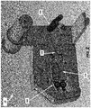
- Figure 2 illustrates a perspective view of the packaging apparatus 10 with sealing apparatus covers 12 removed exposing the sealing apparatus 100.
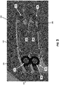
- Figure 3 illustrates a perspective view of the sealing apparatus 100 of the packaging apparatus 10.
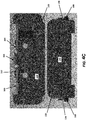
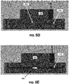
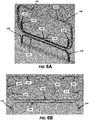
- Figures 4A through 4E illustrate embodiments of a portion of the sealing apparatus 100.
- the sealing apparatus 100 comprises a first support member 110 (e.g., a first sealing block, or the like) and a second support member 130 (e.g., a second sealing block).
- first sealing block 110 may comprise a first heating element 112 operatively coupled to the first sealing block 110
- the second sealing block 130 may comprise a second heating element 132 operatively coupled to the second sealing block 130.
- the first heating element 112 and/or the second heating element 132 may comprise heating ribbons. It should be understood that while the heating elements 112, 132 are illustrated in the figures as a heating ribbons, the heating elements 112, 132 can be any type of heating element of any size and/or shape.
- the first sealing block 110 and/or the second sealing block 130 may include a channel 118, 138 (e.g., groove, embossment, or the like) in which the heating elements 112, 132 (e.g., heating ribbons, or the like) may be located.
- First ends 114, 134 and second ends 116, 136 of each heating element 112, 132 may be operatively coupled to the first sealing block 110 and the second sealing block 130, respectively, using a connector, such as a fastener 108 (e.g., a screw, bolt, rivet, or the like), as illustrated with respect to the second sealing block 130 illustrated in Figures 4A-4C .
- a connector such as a fastener 108 (e.g., a screw, bolt, rivet, or the like), as illustrated with respect to the second sealing block 130 illustrated in Figures 4A-4C .
- At least one of the first sealing block 110 or the second sealing block 130 may comprise a protective member 160.
- the protective member 160 may be a shim, such as a ribbon shim (e.g., same or similar size as the heating ribbon, or the like), which may be utilized to cover at least a portion a first heating element 112 or a second heating element 132.
- the protective member 160 may be operatively coupled to the first sealing block 110 or the second sealing block 130 (e.g., depending on which sealing block has a sensor 180). In some embodiments, the protective member 160 may be operatively coupled to a sealing block 110, 130 using an adjustment member 168.
- the adjustment member 168 may be a biasing member (e.g., a spring, or the like) that may operatively couple a first end 162 of a protective member 160 to a second end 164 of a protective member 160.
- the adjustment member 168 may be utilized to account for heating and cooling of the protective member 160, which may cause expansion and/or contraction of the protective member 160. As such, the adjustment member 168 may compress when the protective member 160 is heated (and thus expands) and tensioned when the protective member cools (and thus contracts). In this way, the adjustment member 168 accounts for the heating and cooling cycles of the heating elements 112, 132 such that the protective member 160 remains operatively coupled to the sealing blocks 110, 130 and protects the sensor 180 during operation of the packaging apparatus 10. It should be understood that in some embodiments at least a portion of the protective member 160 is located within a channel 118, 138 of the sealing blocks 110, 130.
- the sealing apparatus 100 further comprises a film feed mechanism 102.
- the film feed mechanism 102 may comprise a first feed mechanism 120 that is operatively coupled to the first sealing block 110.
- the first feed mechanism 120 may comprise a first belt 122 operatively coupled to one or more first belt rollers, such as one or more first belt drive rollers 124 and/or one or more first belt guide rollers 126.
- the film feed mechanism 102 may further comprise a second feed mechanism 140 that is operatively coupled to the second sealing block 130.
- the second feed mechanism 140 may comprise a second belt 142 operatively coupled to one or more second belt rollers, such as one or more second belt drive rollers 144 and/or one or more second belt guide rollers 146.
- the one or more first belt rollers and/or the one or more second belt rollers may drive the first belt 122 and the second belt 142 in order to pass the film material between the belts 122, 142 between the heating elements 112, 132 of the first sealing block 110 and the second sealing block 130.
- a sensor 180 is operatively coupled between the protective member 160 and a heating element 112, 132.
- the sensor 180 may be a temperature sensor, such as thermocouple, that is located between the protective member 160 and a heating element 112, 132.
- a single sensor 180 may be located between the first protective member 160 and the first heating element 112 of the first sealing block 110.
- multiple sensors 180 may be located between the first protective member 160 and the first heating element 112 along different locations of the foregoing (e.g., along the length of the heating element ribbon and protective ribbon shim, or the like). In this way multiple sensors 180 may be used to determine the sealing temperature (e.g., at different locations, and average temperature, or the like).
- one or more sensors 180 may also be used between a second protective member (not illustrated) and the second heating element 132 of the second sealing block 130.
- the protective member 160 described herein is utilized, in part, to protect the sensor 180 from damage that might otherwise occur from the belts 122, 142 rubbing across the sensor 180 over time.
- the protective member 160 is the component that interacts with the belts 122, 142 instead of the sensor 180.
- the one or more sensors 180 may be operatively coupled between the protective member 160 and the heating element 112, 132 through the use of a spot weld of the one or more sensors 180 to the protective member 160 and/or the heating elements 112, 132.
- a sensor may result in inaccurate temperature readings because the sensor is located away from the sealing zone, and moreover, the sealing blocks 110, 130 may act as a heat sinks.
- using an IR sensor instead of a thermocouple to measure the temperature of the belts 122, 142 through which the film material is passed may also result in errors. That is, the belts are constantly being moved in and out of the sealing zone and may be heated and/or cooled as the belts move in and out of the heating zone and/or through friction of the belts against the one or more rollers of the film feed mechanism 102. As such, using an IR sensor to determine the temperature of the sealing zone may also provide for inaccurate readings. Moreover, the IR sensor readings may not be timely enough to make adjustments to the temperature of the heating elements as needed.
- the temperature registered by the sensor 180 is more accurate.
- utilizing the sensor 180 between the heating element 112, 132 and the protective member 160 allows for much faster determination of the sealing temperature because the sensor remains close to the sealing zone. That is, the sensor 180 is closer to the film material upon sealing (e.g., as compared to a thermocouple sensor located on a support block).
- the sensor 180 is located between two components (e.g., the heating elements 112 or 132 and the protective member 160), which have approximately the same temperature.
- the protective member 160 may be made of a material that can quickly heat up and cool down as the same, or approximately the same, rate as the heating elements 112, 132. As such, heat sinks around the sensor 180 are avoided because the materials with which the one or more sensors 180 contact are the same as, or similar to, each other and/or to the temperature of the sealing zone in which the film material is sealed.
- the sealing apparatus 100 may comprise the sealing blocks 110, 130 as described and illustrated herein. Moreover, the sealing apparatus 100 may utilize multiple heating elements 112, 132, one or more sensors 180 and/or one or more protective members 160. However, in other embodiments the sealing apparatus 100 may comprise a single sealing block 110 with a single heating element 112 to which one or more sensors 180 are operatively coupled and protected by the protective member 160.
- the film material may be feed through the sealing apparatus 100 through the use of the film feed mechanism 102.
- the heating elements 112, 132 may be engaged, such as by heating the heating elements 112, 132.
- the first sealing block 110 and the second sealing block 130 and/or the heating elements 112, 132 thereof may static, or alternatively, the first sealing block 110 and/or the second sealing block 130 and/or the heating elements 112, 132 thereof may be moved into position (e.g., one block or both blocks, or one heater or both heaters, may move towards and away from each other).
- a component of the blocks 110, 130 may move the heating elements 112, 132 towards each other without moving the entire block 110, 130.
- the heating elements 112, 132 may melt at least a portion of the film material in order to seal the one or more chambers that have been filled with a fluid by the fluid supply apparatus 300.
- the packaging apparatus 10 may further comprise a pinch roller apparatus 200, which is used to provide an improved way to feed the film material to the sealing apparatus 100, which allows for more efficiently and effectively filing the one or more chambers of the film material.
- the pinch roller apparatus 200 may receive film material from a film supply (e.g., a supply roller 240), and may compresses the film material as it passes through the pinch roller apparatus 200. This compression of the film restricts (e.g., stops, impedes, or the like) fluid from flowing within the film material past the pinch roller apparatus 200 back to the supply of film material, which could cause the film material to move around (e.g., slide off of a roll of film material, or the like) and not feed onto the sealing apparatus 100 correctly.
- a film supply e.g., a supply roller 240
- This compression of the film restricts (e.g., stops, impedes, or the like) fluid from flowing within the film material past the pinch roller apparatus 200 back to the supply of film material, which could cause the film material to move
- the pinch roller apparatus 200 creates a sealed portion of the film material such that a fluid supply assembly 300 (e.g., a nozzle and/or blower) can generate pressure to fill and expand the one or more chambers in the film material between the sealing apparatus 100 (or the fluid supply apparatus 300) and the pinch roller apparatus 200.
- a fluid supply assembly 300 e.g., a nozzle and/or blower
- the geometry of the one or more rollers 202 e.g., the one or more pinch rollers 212, the one or more guide rollers 222, or the like
- the orientation of the one or more rollers 202 with respect to the film supply e.g., the orientation of the film supply roller 240
- the inlet of the sealing apparatus 100 may be used to evenly stretch the film material.
- the film material may be stretched as the one or more chambers expand in order to allow for even tension of the film material, and to reduce the bunching (e.g., the folds, wrinkles, or the like) that can occur within the film material, both of which provide proper feeding of the film material to the fluid supply apparatus 200 and/or the sealing apparatus 100.
- the bunching e.g., the folds, wrinkles, or the like
- the pitch roller apparatus 200 may comprise a plurality of rollers 202, such as first roller 210, a second roller 210, or the like.
- the first roller 210 may comprise a pinch roller 212
- the second roller 220 may comprise a guide roller 222.
- the first roller 210 and the second roller 220 may both be pinch rollers 212 (e.g., may both rotate around an arm as well as spin around a longitudinal axis).
- one or more of the rollers 202 may be moveable to allow for threading of the film material within the pinch roller apparatus 200.
- a pinch roller 212 may be moveable, such as rotatable around a pivot 214 located a distance away from a longitudinal access of the pinch roller 212.
- the guide roller 222 may be static such that a longitudinal access of the guide roller 222 does not change position. Both the pinch roller 212 and the guide roller 222 may rotate around their longitudinal axes (e.g., spin), respectively.
- the one or more rollers 202 may have a uniform surface (e.g., cylindrical, or the like), a non-uniform surface, or the like.
- a first roller 210 e.g., a pinch roller 212
- a second roller 220 e.g., a guide roller 222
- the non-uniform second roller 220 may have a uniform portion 224 (e.g., a cylindrical portion, or the like) and a non-uniform portion 226 (e.g., a diverging portion extending from the uniform portion 224).
- the non-uniform surface may include any type of surface, such as, a portion (or all of the roller) that may be converging, diverging, curved, angled, convex, concave, hyperbolic, parabolic, sinusoidal, or the like. While the illustrated embodiments indicate only one of the rollers 202 have a non-uniform surface, it should be understood that both, or neither, of the rollers 202 may have a non-uniform surface.
- the one or more rollers 202 may be positioned at an angled orientation with respect to the plane of the inlet of the sealing apparatus 100 and/or the longitudinal axis of the film supply roller 240 that holds a supply of film material (e.g., roll of film material).
- the one or more rollers 202 in particular the second roller 220, may be orientated at an angle with respect to the longitudinal axis of the film supply roller 240 (and/or with respect to the plane of the inlet of the sealing apparatus 100).
- the "a" angle may be 1, 2, 3, 4, 5, 6, 7, 8, 9, 10, 12, 14, 16, 18, 20, 25, 30, 35, or other like degree.
- the angle “a” may range between, overlap, fall within, or fall outside of any of these degree values.
- the one or more rollers 202 in particular the first roller 210, may be orientated at an angle with respect to the longitudinal axis of the film supply roller 240 (and/or with respect to the plane of the inlet of the sealing apparatus 100).
- the "b" angle may be 1, 2, 3, 4, 5, 6, 7, 8, 9, 10, 12, 14, 16, 18, 20, 25, 30, 35, or other like degree.
- the angle “b” may range between, overlap, fall within, or fall outside of any of these degree values.
- a first roller 210 may have a converging surface
- a second roller 220 may have a diverging surface
- first roller 210 and the second roller 220 may be in plane (e.g., parallel) with the film supply (e.g., film supply roller 240) and/or the inlet of the sealing apparatus 100
- the surfaces of the first roller 210 and the second roller 220 may change the angle of orientation of the film material such that it is out of plan with respect to the film material exiting the film supply (e.g., film supply roller 240) and/or the inlet of the sealing apparatus 100.
- the film material exiting a film supply on the film supply roller 240 may be located in the same plane (e.g., longitudinally parallel with the film supply roller 240) with the film material entering into the inlet of the sealing apparatus 100 (e.g., longitudinally parallel with the belts of the film feed mechanism 202.
- the film material passing through the pinch roller apparatus 200 is out of plane with respect to the longitudinal axis of the supply roller 240 and the plane of the belts 122, 142 in the sealing apparatus 100.
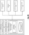
- the packaging apparatus 10 may further comprise a controller 20 that is used to operate the packaging apparatus 10, in accordance with some embodiments of the invention.
- the controller 20 may comprise one or more communication components 22, one or more processing components 24, and/or one or more memory components 26.
- the one or more processing components 24 are operatively coupled to the one or more communication components 22 and the one or more memory components 16.
- the term "processing component” generally includes circuitry used for implementing the communication and/or logic functions of a particular system.
- a processing component 24 may include a digital signal processor component, a microprocessor component, and various analog-to-digital converters, digital-to-analog converters, and other support circuits and/or combinations of the foregoing. Control and signal processing functions of the system are allocated between these processing components according to their respective capabilities.
- the one or more processing components 24 may include functionality to operate one or more software programs based on computer-readable instructions 28 thereof, which may be stored in the one or more memory components 26.
- the one or more processing components 24 use the one or more communication components 22 to communicate with an operator.
- the one or more communication components 22 may include a keypad, keyboard, touchscreen, touchpad, microphone, mouse, joystick, other pointer component, button, soft key, speaker, and/or other input/output component(s) for communicating with an operator through input and/or output signals.
- the one or more communication components 22 may generally comprise a wireless transceiver, modem, server, electrical connection, electrical circuit, or other component for communicating with other components on the network 2.
- the one or more communication components 22 may further include an interface that accepts one or more network interface cards, ports for connection of network components, Universal Serial Bus (USB) connectors, or the like to provide for a wired communication, removable device communication, or the like.
- communication may be made with an operator through an operator computer system.
- the operator computer system may be a desktop, mobile device (e.g., laptop, smartphone device, PDA, tablet, or other mobile device), control station, or any other type of computer that generally comprises one or more communication components, one or more processing components, and one or more memory components.
- an operator may communicate with the controller 20 of the packaging apparatus 10 directly (e.g., through a touchscreen, or the like) or indirectly (e.g., through an operator mobile device) in order to operate the controller 20.
- the controller 20 may have computer-readable instructions 28 stored in the one or more memory components 26, which in one embodiment includes the computer-readable instructions 28 for controller applications 29, such as dedicated applications (e.g., apps, applet, or the like), portions of dedicated applications, a web browser or other apps that allow an operator to take various actions, including allowing the operator to control the packaging apparatus 10 through the controller 20.
- controller applications 29 such as dedicated applications (e.g., apps, applet, or the like), portions of dedicated applications, a web browser or other apps that allow an operator to take various actions, including allowing the operator to control the packaging apparatus 10 through the controller 20.
- the operator may select the type of film material (e.g., pillow cushions, bubble wrap, or the like), the velocity of fluid to fill the one or more chambers of the film material, the speed at which the film material will pass through the sealing apparatus 100, the time at which the packaging apparatus 10 will run, or the like.
- the operating parameters that may be selected by an operator may be stored in a datastore 27 and accessed by the controller application 29
- the controller 20 is operatively coupled to the one or more heating elements 112, 132, the one or more sensors 180, the fluid supply apparatus 300 (e.g., a blower, or the like operatively coupled to the nozzle), and/or the film feed mechanism 202 (e.g., a motor thereof), and is configured to send information to and/or receive information from each of the foregoing and/or other components in order to operate the packaging apparatus 10 as described herein.
- the fluid supply apparatus 300 e.g., a blower, or the like operatively coupled to the nozzle
- the film feed mechanism 202 e.g., a motor thereof
- Figure 9 illustrates a process flow 400 for the operation of the packaging apparatus 10.
- the film supply e.g., roll of film
- a first roller 210 such as the pinch roller 212
- a second roller 220 such as the guide roller 222
- the film material may be pulled away from the film supply (e.g., unroll the film roll, or the like) and threaded through the space between the first roller 210 and the second roller 220.
- the film material may then be operatively coupled to the nozzle and/or the sealing apparatus 100.
- at least a portion of the film material may be slid over the nozzle. That is, a fill channel within the film material is slid over the end of the nozzle and at least a portion of the film material (e.g., an end of the film material) is inserted into the inlet of the sealing apparatus 100.
- the first roller 210 e.g., the pinch roller 212
- the second roller 220 e.g., the guide roller 222
- Block 420 of Figure 9 illustrates that the controller 20 of the packaging apparatus 10 receives a selection of one or more operating parameters for the operation of the packaging apparatus 10 (e.g., through a touchscreen, or the like).
- an operator may select the type of film material being used (e.g., cushion pillows, bubble wrap, or the like), a film material size (e.g., thickness, or the like), the fluid flow (e.g., air flow volume and/or air speed provided by the blower and/or exiting the nozzle outlet) for filling the one or more chambers of the film material, the speed of the feed of the film material into the sealing apparatus 100 (e.g., speed of the film feed mechanism 102), the duration of the operation of the packaging apparatus (e.g., time of operation), the length of the film material to inflate (e.g. feet, yards, or the like), or other like operating parameters of the packaging apparatus 10.
- the operator may input the operating parameters into the controller 20 (e.g., through a touchscreen) such that the controller 20 may
- Block 430 of Figure 9 illustrates that a sealing temperature for the sealing apparatus 100 is determined for the operation of the sealing apparatus 100 based on the operating parameters selected by the operator, as described with respect to block 420 of Figure 9 .
- the sealing temperature at which to seal the film material is based on stored temperature values that are determined based on the operating parameters input into the sealing apparatus 100.
- the sealing temperature may be looked up in a reference table based on the selection of the film material type, the film thickness, the fluid flow, duration of the operation of the packaging apparatus, the length of film material to inflate, and/or the like.
- Figure 9 further illustrates in block 440 that the packaging apparatus 100 is activated for operation based on the selected operating parameters, as described with respect to blocks 420 and 430 of Figure 9 . That is, the controller 20 first activates the one or more heating elements 112, 132 in order to heat the one or more heating elements 112, 132 to the determined sealing temperature.
- Block 450 of Figure 9 illustrates that the controller 20 may monitor the temperature reading of the one or more sensors 180 (e.g., located between the one or more heating elements 112, 132 and the one or more protective members 160), and thus, the temperature of the one or more heating elements 112, 132 and/or the sealing zone in which the film material will be sealed.
- the controller 20 monitors the temperature reading of the one or more sensors 180 in order to determine when the packaging apparatus 10 is ready to inflate the one or more chambers of the film material and seal the one or more chambers.
- Figure 9 further illustrates in block 460 that once the sealing temperature determined by the controller 20, as described with respect to block 430, meets the operating temperature measured by the one or more sensors 180, the fluid supply apparatus 300 (e.g., the blower) and/or the film feed mechanism 102 are activated.
- the fluid supply apparatus e.g., blower
- the film feed mechanism 102 will begin to feed the film material into the sealing apparatus 100 to seal the one or more chambers that have been inflated by the fluid supply apparatus 300 (e.g., blower and nozzle).
- the controller 20 will continue to monitor the readings from the one or more sensors 180, and thereafter, adjust the one or more heating elements 112, 132 should the operating temperature not meet the sealing temperature (or fall within a range for the sealing temperature).
- Block 370 of Figure 9 further illustrates that once the packaging apparatus 10 has inflated the film material and sealed the one or more inflated chambers of the fill material to form the inflated article (e.g., packaging material) in accordance with the operating parameters entered into the controller 20, the operation of the packaging apparatus 10 may be ceased.
- the packaging apparatus 10 has inflated the film material and sealed the one or more inflated chambers of the fill material to form the inflated article (e.g., packaging material) in accordance with the operating parameters entered into the controller 20, the operation of the packaging apparatus 10 may be ceased.
- the present invention provides improvements over traditional packaging apparatuses, due at least in part to the improved sealing apparatus 100 and the pinch roller apparatus 200.
- improved filling of the one or more chambers may be achieved.
- the film entering and exiting the pinch roller apparatus 200 may be twisted out of plane with respect to the orientation of the film material being received from the film supply (e.g., film supply roll 240) and/or the film material being fed into to the inlet of the sealing apparatus 100.
- the pinch assembly 100 stretches out the film material to restrict bunching (e.g. folding, wrinkling, or the like) of the film material before being filled with fluid and/or sealed.
- the sealing apparatus 100 of the present disclosure provides an improved sealing of the one or more inflated chambers by more accurately determining the sealing temperature within the sealing zone in order to more accurately control the sealing of the one or more chambers to provide a desired seal within the inflated fill material. It should be understood that by more accurately being able to measure the temperature of the sealing zone, the sealing apparatus 100 may avoid over-heating and/or under-heating of the film material, either of which could result in an improper seal of the one or more chambers.
- An improper seal may be an underseal (e.g., the film material is unsealed) or an overseal (e.g., the film material is over melted such that burn through of the film material occurs), both of which could result in fluid leaking from the one more of the chambers, and thus, resulting in defective packaging material.
- an underseal e.g., the film material is unsealed
- an overseal e.g., the film material is over melted such that burn through of the film material occurs
- the systems, devices, and components described in herein may be configured to operate through the use of the controller 20 and/or the components thereof by establishing an electronic communications link between components and sending signals in order to accomplish the steps of the processes described herein.
- the process flows described herein include transforming the information sent to and/or received from the controller application 29 from one or more data formats into a data format associated with each individual component. There are many ways in which information is converted within the controller 20. This may be seamless, as in the case of receiving continuous information.
- the conversion may require processing by the use of a special conversion program, or it may involve a complex process of going through intermediary stages, or involving complex "exporting" and "importing” procedures, which may convert to and from a tab-delimited or comma-separated text files.
- the operator application 29 may recognize several data file formats at the data input stage and then is also capable of storing the output data in a number of different formats. Such an operator application 29 may be used to convert a file format. If the source format or target format is not recognized, then at times a third program may be available which permits the conversion to an intermediate format, which can then be reformatted by the operator application 29.
- the present disclosure may be embodied as a method (including, for example, a computer-implemented process), apparatus (including, for example, a system, machine, device, computer program product, and/or the like), or a combination of the foregoing. Accordingly, embodiments of the present disclosure may take the form of an entirely hardware embodiment, an entirely software embodiment (including firmware, resident software, micro-code, etc.), or an embodiment combining software and hardware aspects that may generally be referred to herein as a "system.” Furthermore, embodiments of the present disclosure may take the form of a computer program product on a computer-readable medium having computer-executable program code embodied in the medium.
- the computer readable medium may be, for example but not limited to, an electronic, magnetic, optical, electromagnetic, infrared, or semiconductor system, apparatus, or device. More specific examples of the computer readable medium include, but are not limited to, the following: an electrical connection having one or more wires; a tangible storage medium such as a portable computer diskette, a hard disk, a random access memory (RAM), a read-only memory (ROM), an erasable programmable read-only memory (EPROM or Flash memory), a compact disc read-only memory (CD-ROM), or other optical or magnetic storage device.
- RAM random access memory
- ROM read-only memory
- EPROM or Flash memory erasable programmable read-only memory
- CD-ROM compact disc read-only memory
- a computer readable medium may be any medium that can contain, store, communicate, or transport the program for use by or in connection with the instruction execution system, apparatus, or device.
- the computer usable program code may be transmitted using any appropriate medium, including but not limited to the Internet, wireline, optical fiber cable, radio frequency (RF) signals, or other mediums.
- RF radio frequency
- Computer-executable program code for carrying out operations of embodiments of the present disclosure may be written in an object oriented, scripted or unscripted programming language such as Java, Perl, Smalltalk, C++, or the like.
- the computer program code for carrying out operations of embodiments of the present disclosure may also be written in conventional procedural programming languages, such as the "C" programming language or similar programming languages.
- Embodiments of the present disclosure are described above with reference to flowchart illustrations and/or block diagrams of methods, apparatuses (systems), and computer program products. It will be understood that each block of the flowchart illustrations and/or block diagrams, and/or combinations of blocks in the flowchart illustrations and/or block diagrams, can be implemented by computer-executable program code portions. These computer-executable program code portions may be provided to a processor of a general purpose computer, special purpose computer, or other programmable data processing apparatus to produce a particular machine, such that the code portions, which execute via the processor of the computer or other programmable data processing apparatus, create mechanisms for implementing the functions/acts specified in the flowchart and/or block diagram block or blocks.
- These computer-executable program code portions may also be stored in a computer-readable memory that can direct a computer or other programmable data processing apparatus to function in a particular manner, such that the code portions stored in the computer readable memory produce an article of manufacture including instruction mechanisms which implement the function/act specified in the flowchart and/or block diagram block(s).
- the computer-executable program code may also be loaded onto a computer or other programmable data processing apparatus to cause a series of operational steps to be performed on the computer or other programmable apparatus to produce a computer-implemented process such that the code portions which execute on the computer or other programmable apparatus provide steps for implementing the functions/acts specified in the flowchart and/or block diagram block(s).
- computer program implemented steps or acts may be combined with operator or human implemented steps or acts in order to carry out an embodiment of the invention.
- Embodiments of the present disclosure are described above with reference to flowcharts and/or block diagrams. It will be understood that steps of the processes described herein may be performed in orders different than those illustrated in the flowcharts. In other words, the processes represented by the blocks of a flowchart may, in some embodiments, be in performed in an order other that the order illustrated, may be combined or divided, or may be performed simultaneously. It will also be understood that the blocks of the block diagrams illustrated, in some embodiments, merely provide conceptual delineations between components and that one or more of the components illustrated by a block in the block diagrams may be combined or share hardware and/or software with another one or more of the components illustrated by a block in the block diagrams.
- a component, device, system, apparatus, and/or the like may be made up of one or more components, devices, systems, apparatuses, and/or the like.
- the processor may be made up of a plurality of microprocessors or other processing devices which may or may not be coupled to one another.
- the memory may be made up of a plurality of memory devices which may or may not be coupled to one another.
- any terms expressed in the singular form herein are meant to also include the plural form and/or vice versa, unless explicitly stated otherwise. Accordingly, the terms “a” and/or “an” shall mean “one or more.”
- a processor may be "configured to" perform a certain function in a variety of ways, including, for example, by having one or more general-purpose circuits perform the function by executing particular computer-executable program code embodied in computer-readable medium, and/or by having one or more application-specific circuits perform the function.
- operatively coupled when used herein, means that the components may be formed integrally with each other, or may be formed separately and coupled together. Furthermore, “operatively coupled” means that the components may be coupled directly to each other, or to each other with one or more components located between the components that are operatively coupled together. Furthermore, “operatively coupled” may mean that the components are detachable from each other, or that they are permanently coupled together.
Landscapes
- Engineering & Computer Science (AREA)
- Mechanical Engineering (AREA)
- Physics & Mathematics (AREA)
- General Physics & Mathematics (AREA)
- Thermal Sciences (AREA)
- Package Closures (AREA)
- Containers And Plastic Fillers For Packaging (AREA)
Abstract
Description
- The present Application for a Patent claims priority to United States Provisional Patent Application Serial No.
62/714,853 - This application relates generally to the field of packaging apparatuses, and more particularly to a sealing apparatus with a sensor and a pinch roller apparatus for improved feeding and sealing of film material during operation of a packaging apparatus.
- Packaging apparatuses utilize varying speeds and fluid inflation rates to fill chambers of film material (e.g., air pillows, bubble wrap, or the like) with the desired amount of fluid (e.g., air, gas, or the like) based on the film material and the application in which the inflated article (e.g., inflated film material) will be utilized. In order to fill the chambers for the desired application, proper filling and sealing of the chambers is required.
- The present disclosure provides apparatuses, systems, methods, and computer program products for packaging apparatuses and the use thereof. The packaging apparatus of the present disclosure comprises components that improve the delivery of the film material, filling of the film material with fluid (e.g., air, gas, or the like), and sealing of the inflated film material to create the inflated article. As such, a pinch roller apparatus (e.g., comprising one or more guide and/or pinch rollers) is used to deliver film material to a fluid supply apparatus (e.g., nozzle and blower apparatus, or the like) that fills one or more chambers of the film material with fluid (e.g., air, gas, or other like fluid), and the film material is then sealed by a sealing apparatus (e.g., using one or more heating elements with an improved temperature sensor configuration) that seals the fluid within the one or more chambers in order to form the inflated article (e.g., inflated packaging material). In particular, the sealing apparatus provides an improved apparatus for sealing the one or more inflated chambers of the film material by improving the accuracy of the temperature reading in the heating zone, and thus, providing improved control of the one or more heating elements within the sealing apparatus used for sealing the film material. Furthermore, the pinch roll apparatus improves the delivery of the film material to the fluid supply apparatus and the sealing apparatus by pinching at least a portion of the film material to resist the backflow of fluid to the film supply, and orienting the film material to improve the delivery of the film material to the sealing apparatus by reducing or removing the bunching (e.g., folds, wrinkles, or the like) in the film material.
- The sealing apparatus of the present disclosure utilizes an improved sensor configuration (e.g., thermocouple configuration, or the like) in which a sensor is operatively coupled (e.g., spot welded, or the like) between a protective member (e.g., a thermally conductive metal shim, or the like) and a heating element (e.g., a resistive heater wire, or the like), as will be discussed in further detail herein. Typical sealing apparatuses have a problem capturing consistent temperature readings in order to accurately estimate the temperature in the sealing zone (e.g., heat sealing zone) in which the film material is sealed. The present invention locates one or more sensors in an improved location in order to more accurately determine temperature readings within the sealing zone, and furthermore, covers the one or more sensors using a protective member in order to minimize damaging the one or more sensors.
- Additionally, the pinch roller apparatus (e.g., the two rollers, such as a guide roller, a pinch roller, or the like) compresses the film material and positions the film material (e.g., changes the plane of the film material) as it passes through the rollers to restrict bunching (e.g., folds, wrinkles, or the like) of the film material. This compression of the film material restricts (e.g., stops, impedes, or the like) the fluid from flowing along the one or more fill channels of the film material into the film supply (e.g., film roll, or the like), which could cause the film to move around and not feed onto the fluid supply apparatus properly. The pinch roller apparatus also creates a section of the film material between the fluid supply apparatus (e.g., fill nozzle, or the like) and/or the sealing apparatus, and the pinch roller apparatus, in order to seal off the fill channels of the film material to provide improved fluid inflation of the one or more chambers of the film material. The section of the film material created for inflation provides the fluid supply apparatus the ability to generate pressure to expand the one or more chambers of the film material with the fluid. Furthermore, the geometry and orientation of the pinch roller apparatus, and the rollers thereof (e.g., the pinch roller, the guide rollers, or the like), within the packaging apparatus stretches the film material out to provide for even expansion of the one or more chambers as they expand with fluid. For example, the out of plane orientation of the of the one or more rollers (e.g., the guide roller, the pinch roller) that changes the orientation of the film material and/or the curved and/or angled portions of the surfaces of the one more rollers allows for even tension of the film material, which may reduce bunching (e.g., wrinkles, folds, or the like) that can occur within the film material.
- In some embodiments, a packaging apparatus is provided, which comprises a sealing apparatus or a pinch roll apparatus. The sealing apparatus comprises a support member; a heating element operatively coupled to the support member; a protective member operatively coupled to the heating element; and a sensor operatively coupled to the heating element or the protective member, such that the sensor is configured to determine a temperature for sealing a film material. Moreover, the pinch roll apparatus comprises a first roller; and a second roller operatively coupled to the first roller such that the first roller is adjustable with respect to the second roller to guide the film material while the film material is inflated by a nozzle apparatus.
- In some embodiments, or in combination with any of the above embodiments, the packaging apparatus comprises the sealing apparatus and the pinch roll apparatus.
- In some embodiments, or in combination with any of the above embodiments, the sensor is operatively coupled between the heating element and the protective member, and the protective member interacts with the film material to seal the film material.
- In some embodiments, or in combination with any of the above embodiments, the packaging apparatus further comprises a film supply member with a supply longitudinal axis, such that the film supply member is confirmed to support a spool of film material that rotates around the longitudinal axis of the film supply. Here, the first roller or the second roller each have a roller longitudinal axis, wherein the roller longitudinal axis is angled with respect to the supply longitudinal axis. Moreover, the first roller is moveable with respect to the second roller. Also, the first roller or the second roller comprises a diverging portion in which a surface diverges from a first cross-sectional area to a second cross-sectional area that is smaller than the first cross-sectional area.
- In some embodiments, or in combination with any of the above embodiments, a sealing apparatus is provided, which comprises a support member; a heating element operatively coupled to the support member; a protective member operatively coupled to the heating element; and a sensor operatively coupled to the heating element or the protective member; such that the sensor is configured to determine a temperature for sealing one or more chambers of a film material.
- In some embodiments, or in combination with any of the above embodiments, the sensor is a temperature sensor.
- In some embodiments, or in combination with any of the above embodiments, the temperature sensor is a thermocouple.
- In some embodiments, or in combination with any of the above embodiments, the sensor is operatively coupled between the heating element and the protective member, and the protective member interacts with the film material to seal the film material.
- In some embodiments, or in combination with any of the above embodiments, the protective member is a shim.
- In some embodiments, or in combination with any of the above embodiments, the protective member is operatively coupled to the support member using an adjustment element.
- In some embodiments, or in combination with any of the above embodiments, the protective member expands and contracts as a temperature of the heating element increases and decreases. The adjustment element adjusts the protective member due to the heating and cooling of the protective member element.
- In some embodiments, or in combination with any of the above embodiments, the adjustment element is a spring.
- In some embodiments, or in combination with any of the above embodiments, the support member comprises a first support member and the heating element is a first heating element. Here, the packaging apparatus further comprises a second support member, wherein the second support member comprises a second heating element, such that the film material passes between the protective member and the second heating element to seal the one or more chambers of the film material.
- In some embodiments, or in combination with any of the above embodiments, the packaging apparatus further comprises a film feeding component. The film feeding component comprises a first belt, a second belt, and one or more drive mechanisms, wherein the one or more drive mechanisms drive the first belt or the second belt to move the film material through the sealing component.
- In some embodiments, or in combination with any of the above embodiments, a pinch roller apparatus is provided, which comprises a first roller; and a second roller operatively coupled to the first roller. The first roller is adjustable with respect to the second roller to guide the film while the film is inflated by a nozzle apparatus,
- In some embodiments, or in combination with any of the above embodiments, the first roller comprises a pinch roller, and the second roller comprises a guide roller.
- In some embodiments, or in combination with any of the above embodiments, the first roller and the second roller are pinch rollers that are both adjustable with respect to each other.
- In some embodiments, or in combination with any of the above embodiments, a film supply member a supply longitudinal axis, wherein the film supply member is confirmed to support a spool of film material that rotates around the longitudinal axis of the film supply. The first roller or the second roller each have a roller longitudinal axis, and the roller longitudinal axis is angled with respect to the supply longitudinal axis.
- In some embodiments, or in combination with any of the above embodiments, the first roller or the second roller comprises a diverging portion in which a surface diverges from a first cross-sectional area to a second cross-sectional area that is smaller than the first cross-sectional area.
- In some embodiments, or in combination with any of the above embodiments, a method of operating a package apparatus is provided. The method comprises the steps of identifying a temperature of a protective member of a sealing apparatus using a sensor; inflating one or more chambers of a film material with a fluid using a nozzle when the temperatures meets a desired temperature; and feeding the film material through the sealing apparatus; sealing the one or more chambers of the film material using the sealing apparatus. Here, the sealing apparatus comprises a support member; a heating element operatively coupled to the support member; the protective member operatively coupled to the heating element; and the sensor operatively coupled to the heating element or the protective member; such that the sensor is configured to determine a temperature for sealing a film material. Feeding the film material through the sealing apparatus is optionally perform using a pinch roll apparatus. The pinch roll apparatus comprises a first roller; and a second roller operatively coupled to the first roller; such that the first roller is adjustable with respect to the second roller to guide the film material while the film material is inflated by the nozzle apparatus
- To the accomplishment of the foregoing and the related ends, the one or more embodiments of the invention comprise the features hereinafter fully described and particularly pointed out in the claims. The following description and the annexed drawings set forth certain illustrative features of the one or more embodiments. These features are indicative, however, of but a few of the various ways in which the principles of various embodiments may be employed, and this description is intended to include all such embodiments and their equivalents.
- Features which are described in the context of separate aspects and/or embodiments of the invention may be used together and/or be interchangeable wherever possible. Similarly, where features are, for brevity, described in the context of a single embodiment, those features may also be provided separately or in any suitable sub-combination. Features described in connection with the/each apparatus may have corresponding features definable and/or combinable with respect to a method or vice versa, and these embodiments are specifically envisaged.
- Having thus described embodiments of the invention in general terms, reference will now be made to the accompanying drawings.
-
Figure 1 illustrates a perspective view of the package apparatus, in accordance with some embodiments of the present disclosure. -
Figure 2 illustrates a perspective view of the package apparatus with the sealing apparatus covers removed, in accordance with some embodiments of the present disclosure. -
Figure 3 illustrates a perspective view of the sealing apparatus, in accordance with some embodiments of the present disclosure. -
Figure 4A illustrates a perspective view of a portion of the sealing apparatus, in accordance with some embodiments of the present disclosure. -
Figure 4B illustrates a front view of a portion of the sealing apparatus, in accordance with some embodiments of the present disclosure. -
Figure 4C illustrates a rear view of a portion of the sealing apparatus, in accordance with some embodiments of the present disclosure. -
Figure 4D illustrates an inlet side view of a portion of the sealing apparatus, in accordance with some embodiments of the present disclosure. -
Figure 4E illustrates an outlet side view of a portion of the sealing apparatus, in accordance with some embodiments of the present disclosure. -
Figure 5A illustrates a front perspective view of a first sealing block of the sealing apparatus with the protective member installed, in accordance with some embodiments of the present disclosure. -
Figure 5B illustrates a front perspective view of a first sealing block of the sealing apparatus with the protective member removed, in accordance with some embodiments of the present disclosure. -
Figure 5C illustrates a top view of a first sealing block of the sealing apparatus with the protective member installed, in accordance with some embodiments of the present disclosure. -
Figure 5D illustrates a bottom view of a first sealing block of the sealing apparatus with the protective member and sensor installed, in accordance with some embodiments of the present disclosure. -
Figure 5E illustrates a bottom view of a first sealing block of the sealing apparatus with the protective member removed, in accordance with some embodiments of the present disclosure. -
Figure 5F illustrates a perspective view of a first sealing block of the sealing apparatus with the protective member removed, in accordance with some embodiments of the present disclosure. -
Figure 5G illustrates a bottom view of a first sealing block of the sealing apparatus with the protective member removed, in accordance with some embodiments of the present disclosure. -
Figure 6A illustrates a perspective view of a first heating element and a second heating element with the protective member, in accordance with some embodiments of the present disclosure. -
Figure 6B illustrates a front view of a first heating element and a second heating element with the protective member, in accordance with some embodiments of the present disclosure. -
Figure 7A illustrates a perspective view of the pinch roller apparatus, in accordance with some embodiments of the present disclosure. -
Figure 7B illustrates a front view of the pinch roller apparatus, in accordance with some embodiments of the present disclosure. -
Figure 7C illustrates a top view of the pinch roller apparatus with a supply roller removed, in accordance with some embodiments of the present disclosure. -
Figure 7D illustrates a bottom view of the pinch roller apparatus, in accordance with some embodiments of the present disclosure. -
Figure 8 illustrates a packaging apparatus system environment, in accordance with some embodiments of the present disclosure. -
Figure 9 illustrates a process flow for the operation of the packaging apparatus, in accordance with some embodiments of the present disclosure. - Embodiments of the present disclosure now may be described more fully hereinafter with reference to the accompanying drawings, in which some, but not all, embodiments of the invention are shown. Indeed, the invention may be embodied in many different forms and should not be construed as limited to the embodiments set forth herein; rather, these embodiments are provided so that this disclosure may satisfy applicable legal requirements. Like numbers refer to like elements throughout.
-
Figures 1 through 7D illustrate some embodiments of apackaging apparatus 10 comprising a controller 20 (e.g., control panel touchscreen, or the like) asealing apparatus 100, apinch roller apparatus 200, afilm supply roller 240, and/or fluid supply apparatus 300 (e.g., nozzle and/or blower apparatus, or the like), as well as other components of thepackaging apparatus 10, as will be described herein. Generally, film material in a roll located on afilm supply roller 240 will pass through thepinch roller apparatus 200, which will orient the film material and create a section of film material that can be inflated by thefluid supply apparatus 300. Thefluid supply apparatus 300 may include a nozzle that is inserted into a fill channel of the film material. The nozzle and a blower operatively coupled to the nozzle may fill one or more chambers of the film material (e.g., directly or through the intermediate connection with one or more fill channels) with fluid in order to inflate the film material. A knife operatively coupled to thefluid supply apparatus 300 and/or thesealing apparatus 100 may be utilized to cut a portion of the film material such that the inflated film material may be passed into an inlet of asealing apparatus 100, which is used to heat a portion of the inflated film material and melt the portion of the inflated seal material in order to seal the one or more chambers of the inflated seal material, thus forming the inflated packaging material. - With respect to the
sealing apparatus 100, the sealing apparatus utilizes an improved sensor configuration (e.g., thermocouple configuration, or the like) in which asmall sensor 180 is operatively coupled (e.g., spot welded, or the like) between a protective member 160 (e.g., a thermally conductive metal shim, or the like) and one ormore heating elements Typical packaging apparatuses 10 have a problem capturing consistent temperature readings in order to accurately estimate the temperature in the sealing zone (e.g., heat sealing zone). The present invention locates the sensor in an improved location with aprotective member 160 in order to more accurately capture temperature readings without damaging thesensor 180, as will be described in further detail herein. - The sealing zone is the zone within the sealing
apparatus 100 adjacent one ormore support members 110, 130 (e.g., between two heating blocks, or the like) that support the one ormore heating elements 112, 132 (e.g., resistive heater wires, or the like) that are used to melt the film material. Typically, sealing designs may use the heating elements themselves to measure a temperature (e.g., using the resistance changes in the heating elements to estimate a temperature of theheating elements 112, 132), but theses designs include a lot of noise within the temperature readings, are difficult to calibrate, and/or do not account for external factors (e.g., heat sinks, or the like), and thus, do not provide an accurate temperature reading. Other types of typical designs attached a temperature sensor to the structural support block or utilize an infra-red (IR) sensor to measure belt temperatures. These types of designs also have reduced accuracy, and further have poor response times, both of which lead to low accuracy for temperature readings when compared with invention of the present disclosure, as will be discussed in further detail herein. Generally, the sealingapparatus 100 of the present disclosure uses a protective member (e.g., the thermocouple shim, or other like design) that allows for a more accurate temperature reading due to the close proximity of thesensor 180 in the sealing zone, and provides a response time within milliseconds, both of which allow thepackaging apparatus 10 to ramp up quickly and maintain better control over the temperature in the sealing zone. -
Figure 2 illustrates a perspective view of thepackaging apparatus 10 with sealing apparatus covers 12 removed exposing thesealing apparatus 100. Moreover,Figure 3 illustrates a perspective view of thesealing apparatus 100 of thepackaging apparatus 10. Furthermore,Figures 4A through 4E illustrate embodiments of a portion of thesealing apparatus 100. As illustrated inFigures 2 through 4E , the sealingapparatus 100 comprises a first support member 110 (e.g., a first sealing block, or the like) and a second support member 130 (e.g., a second sealing block). It should be understood that thefirst sealing block 110 may comprise afirst heating element 112 operatively coupled to thefirst sealing block 110, while thesecond sealing block 130 may comprise asecond heating element 132 operatively coupled to thesecond sealing block 130. In some embodiments thefirst heating element 112 and/or thesecond heating element 132 may comprise heating ribbons. It should be understood that while theheating elements heating elements first sealing block 110 and/or thesecond sealing block 130 may include achannel 118, 138 (e.g., groove, embossment, or the like) in which theheating elements 112, 132 (e.g., heating ribbons, or the like) may be located. First ends 114, 134 and second ends 116, 136 of eachheating element first sealing block 110 and thesecond sealing block 130, respectively, using a connector, such as a fastener 108 (e.g., a screw, bolt, rivet, or the like), as illustrated with respect to thesecond sealing block 130 illustrated inFigures 4A-4C . - In some embodiments of the invention at least one of the
first sealing block 110 or thesecond sealing block 130 may comprise aprotective member 160. Theprotective member 160 may be a shim, such as a ribbon shim (e.g., same or similar size as the heating ribbon, or the like), which may be utilized to cover at least a portion afirst heating element 112 or asecond heating element 132. Theprotective member 160 may be operatively coupled to thefirst sealing block 110 or the second sealing block 130 (e.g., depending on which sealing block has a sensor 180). In some embodiments, theprotective member 160 may be operatively coupled to asealing block adjustment member 168. Theadjustment member 168 may be a biasing member (e.g., a spring, or the like) that may operatively couple afirst end 162 of aprotective member 160 to asecond end 164 of aprotective member 160. Theadjustment member 168 may be utilized to account for heating and cooling of theprotective member 160, which may cause expansion and/or contraction of theprotective member 160. As such, theadjustment member 168 may compress when theprotective member 160 is heated (and thus expands) and tensioned when the protective member cools (and thus contracts). In this way, theadjustment member 168 accounts for the heating and cooling cycles of theheating elements protective member 160 remains operatively coupled to the sealing blocks 110, 130 and protects thesensor 180 during operation of thepackaging apparatus 10. It should be understood that in some embodiments at least a portion of theprotective member 160 is located within achannel - The sealing
apparatus 100 further comprises afilm feed mechanism 102. Thefilm feed mechanism 102 may comprise afirst feed mechanism 120 that is operatively coupled to thefirst sealing block 110. Thefirst feed mechanism 120 may comprise afirst belt 122 operatively coupled to one or more first belt rollers, such as one or more firstbelt drive rollers 124 and/or one or more firstbelt guide rollers 126. Thefilm feed mechanism 102 may further comprise asecond feed mechanism 140 that is operatively coupled to thesecond sealing block 130. Thesecond feed mechanism 140 may comprise asecond belt 142 operatively coupled to one or more second belt rollers, such as one or more secondbelt drive rollers 144 and/or one or more secondbelt guide rollers 146. It should be understood that the one or more first belt rollers and/or the one or more second belt rollers may drive thefirst belt 122 and thesecond belt 142 in order to pass the film material between thebelts heating elements first sealing block 110 and thesecond sealing block 130. - A
sensor 180 is operatively coupled between theprotective member 160 and aheating element sensor 180 may be a temperature sensor, such as thermocouple, that is located between theprotective member 160 and aheating element Figures 5D through 5G asingle sensor 180 may be located between the firstprotective member 160 and thefirst heating element 112 of thefirst sealing block 110. Alternatively, in other embodiments,multiple sensors 180 may be located between the firstprotective member 160 and thefirst heating element 112 along different locations of the foregoing (e.g., along the length of the heating element ribbon and protective ribbon shim, or the like). In this waymultiple sensors 180 may be used to determine the sealing temperature (e.g., at different locations, and average temperature, or the like). In still other embodiments, one ormore sensors 180 may also be used between a second protective member (not illustrated) and thesecond heating element 132 of thesecond sealing block 130. Theprotective member 160 described herein is utilized, in part, to protect thesensor 180 from damage that might otherwise occur from thebelts sensor 180 over time. As such, theprotective member 160 is the component that interacts with thebelts sensor 180. - In some embodiments, the one or
more sensors 180 may be operatively coupled between theprotective member 160 and theheating element more sensors 180 to theprotective member 160 and/or theheating elements - There are a number of issues with traditional film sealing devices, most notably, receiving accurate and timely temperature readings in order to accurately control the sealing of the film material in the heat sealing zone (e.g., in the gap between the
first heating element 112 of thefirst heating block 132, and thesecond heating element 132 of the second heating block 130) has been an issue. As previously discussed herein, the typical ways of determining the temperature in the sealing zone may introduce noise into the temperature signal, be difficult to calibrate, and be unable to account for factors outside of the heating element (e.g., when using the change in resistance of theheating elements heating elements 112, 132), may result in inaccurate temperature readings because the sensor is located away from the sealing zone, and moreover, the sealing blocks 110, 130 may act as a heat sinks. Furthermore, using an IR sensor instead of a thermocouple to measure the temperature of thebelts film feed mechanism 102. As such, using an IR sensor to determine the temperature of the sealing zone may also provide for inaccurate readings. Moreover, the IR sensor readings may not be timely enough to make adjustments to the temperature of the heating elements as needed. - Alternatively, it should be understood that by locating the
sensor 180 on the outside face of theheating element 112 the temperature registered by thesensor 180 is more accurate. As such, utilizing thesensor 180 between theheating element protective member 160 allows for much faster determination of the sealing temperature because the sensor remains close to the sealing zone. That is, thesensor 180 is closer to the film material upon sealing (e.g., as compared to a thermocouple sensor located on a support block). Moreover, thesensor 180 is located between two components (e.g., theheating elements protective member 160 may be made of a material that can quickly heat up and cool down as the same, or approximately the same, rate as theheating elements sensor 180 are avoided because the materials with which the one ormore sensors 180 contact are the same as, or similar to, each other and/or to the temperature of the sealing zone in which the film material is sealed. - It should be understood that in some embodiments the sealing
apparatus 100 may comprise the sealing blocks 110, 130 as described and illustrated herein. Moreover, the sealingapparatus 100 may utilizemultiple heating elements more sensors 180 and/or one or moreprotective members 160. However, in other embodiments the sealingapparatus 100 may comprise asingle sealing block 110 with asingle heating element 112 to which one ormore sensors 180 are operatively coupled and protected by theprotective member 160. - Regardless of the configuration of the
sealing apparatus 100, during operation, the film material may be feed through the sealingapparatus 100 through the use of thefilm feed mechanism 102. Theheating elements heating elements first sealing block 110 and thesecond sealing block 130 and/or theheating elements first sealing block 110 and/or thesecond sealing block 130 and/or theheating elements blocks heating elements entire block heating elements heating elements fluid supply apparatus 300. - In addition to the
sealing apparatus 100, thepackaging apparatus 10 may further comprise apinch roller apparatus 200, which is used to provide an improved way to feed the film material to thesealing apparatus 100, which allows for more efficiently and effectively filing the one or more chambers of the film material. In general, thepinch roller apparatus 200 may receive film material from a film supply (e.g., a supply roller 240), and may compresses the film material as it passes through thepinch roller apparatus 200. This compression of the film restricts (e.g., stops, impedes, or the like) fluid from flowing within the film material past thepinch roller apparatus 200 back to the supply of film material, which could cause the film material to move around (e.g., slide off of a roll of film material, or the like) and not feed onto the sealingapparatus 100 correctly. Moreover, thepinch roller apparatus 200 creates a sealed portion of the film material such that a fluid supply assembly 300 (e.g., a nozzle and/or blower) can generate pressure to fill and expand the one or more chambers in the film material between the sealing apparatus 100 (or the fluid supply apparatus 300) and thepinch roller apparatus 200. As will be described in further detail herein, the geometry of the one or more rollers 202 (e.g., the one ormore pinch rollers 212, the one ormore guide rollers 222, or the like), and/or the orientation of the one ormore rollers 202 with respect to the film supply (e.g., the orientation of the film supply roller 240) and/or with respect to the inlet of thesealing apparatus 100, may be used to evenly stretch the film material. For example, the film material may be stretched as the one or more chambers expand in order to allow for even tension of the film material, and to reduce the bunching (e.g., the folds, wrinkles, or the like) that can occur within the film material, both of which provide proper feeding of the film material to thefluid supply apparatus 200 and/or thesealing apparatus 100. - As illustrated in
Figures 7A through 7D , thepitch roller apparatus 200 may comprise a plurality ofrollers 202, such asfirst roller 210, asecond roller 210, or the like. Thefirst roller 210 may comprise apinch roller 212, while thesecond roller 220 may comprise aguide roller 222. However, it should be understood that is some embodiments thefirst roller 210 and thesecond roller 220 may both be pinch rollers 212 (e.g., may both rotate around an arm as well as spin around a longitudinal axis). It should be understood that one or more of therollers 202 may be moveable to allow for threading of the film material within thepinch roller apparatus 200. As illustrated inFigures 7A through 7D , apinch roller 212 may be moveable, such as rotatable around apivot 214 located a distance away from a longitudinal access of thepinch roller 212. Alternatively, theguide roller 222 may be static such that a longitudinal access of theguide roller 222 does not change position. Both thepinch roller 212 and theguide roller 222 may rotate around their longitudinal axes (e.g., spin), respectively. - In some embodiments, the one or
more rollers 202 may have a uniform surface (e.g., cylindrical, or the like), a non-uniform surface, or the like. As illustrated inFigures 7A through 7D , a first roller 210 (e.g., a pinch roller 212) may have a uniform cylindrical surface, while a second roller 220 (e.g., a guide roller 222) may have a non-uniform surface that may include a portion that is diverging. For example, the non-uniformsecond roller 220 may have a uniform portion 224 (e.g., a cylindrical portion, or the like) and a non-uniform portion 226 (e.g., a diverging portion extending from the uniform portion 224). The non-uniform surface may include any type of surface, such as, a portion (or all of the roller) that may be converging, diverging, curved, angled, convex, concave, hyperbolic, parabolic, sinusoidal, or the like. While the illustrated embodiments indicate only one of therollers 202 have a non-uniform surface, it should be understood that both, or neither, of therollers 202 may have a non-uniform surface. - As previously referenced herein, the one or
more rollers 202 may be positioned at an angled orientation with respect to the plane of the inlet of thesealing apparatus 100 and/or the longitudinal axis of thefilm supply roller 240 that holds a supply of film material (e.g., roll of film material). As illustrated inFigure 7C the one ormore rollers 202, in particular thesecond roller 220, may be orientated at an angle with respect to the longitudinal axis of the film supply roller 240 (and/or with respect to the plane of the inlet of the sealing apparatus 100). The "a" angle may be 1, 2, 3, 4, 5, 6, 7, 8, 9, 10, 12, 14, 16, 18, 20, 25, 30, 35, or other like degree. Moreover, the angle "a" may range between, overlap, fall within, or fall outside of any of these degree values. As illustrated inFigure 7D , the one ormore rollers 202, in particular thefirst roller 210, may be orientated at an angle with respect to the longitudinal axis of the film supply roller 240 (and/or with respect to the plane of the inlet of the sealing apparatus 100). The "b" angle may be 1, 2, 3, 4, 5, 6, 7, 8, 9, 10, 12, 14, 16, 18, 20, 25, 30, 35, or other like degree. Moreover, the angle "b" may range between, overlap, fall within, or fall outside of any of these degree values. It should be understood that the "a" angle and the "b" angle may be the same or different in various embodiments of the invention (e.g., based on the shapes of the rollers). For example, in some embodiments afirst roller 210 may have a converging surface, while asecond roller 220 may have a diverging surface. As such, in this embodiment while the longitudinal axes of thefirst roller 210 and thesecond roller 220 may be in plane (e.g., parallel) with the film supply (e.g., film supply roller 240) and/or the inlet of thesealing apparatus 100, the surfaces of thefirst roller 210 and thesecond roller 220 may change the angle of orientation of the film material such that it is out of plan with respect to the film material exiting the film supply (e.g., film supply roller 240) and/or the inlet of thesealing apparatus 100. - Consequently, regardless of the configuration of the
first roller 210 and thesecond roller 220, the film material exiting a film supply on thefilm supply roller 240 may be located in the same plane (e.g., longitudinally parallel with the film supply roller 240) with the film material entering into the inlet of the sealing apparatus 100 (e.g., longitudinally parallel with the belts of thefilm feed mechanism 202. Alternatively, the film material passing through thepinch roller apparatus 200 is out of plane with respect to the longitudinal axis of thesupply roller 240 and the plane of thebelts sealing apparatus 100. - As illustrated in
Figure 8 , thepackaging apparatus 10 may further comprise acontroller 20 that is used to operate thepackaging apparatus 10, in accordance with some embodiments of the invention. Thecontroller 20 may comprise one ormore communication components 22, one ormore processing components 24, and/or one ormore memory components 26. The one ormore processing components 24 are operatively coupled to the one ormore communication components 22 and the one or more memory components 16. As used herein, the term "processing component" generally includes circuitry used for implementing the communication and/or logic functions of a particular system. For example, aprocessing component 24 may include a digital signal processor component, a microprocessor component, and various analog-to-digital converters, digital-to-analog converters, and other support circuits and/or combinations of the foregoing. Control and signal processing functions of the system are allocated between these processing components according to their respective capabilities. The one ormore processing components 24 may include functionality to operate one or more software programs based on computer-readable instructions 28 thereof, which may be stored in the one ormore memory components 26. - The one or
more processing components 24 use the one ormore communication components 22 to communicate with an operator. The one ormore communication components 22 may include a keypad, keyboard, touchscreen, touchpad, microphone, mouse, joystick, other pointer component, button, soft key, speaker, and/or other input/output component(s) for communicating with an operator through input and/or output signals. Alternatively, and/or additionally, the one ormore communication components 22 may generally comprise a wireless transceiver, modem, server, electrical connection, electrical circuit, or other component for communicating with other components on the network 2. Additionally, and/or alternatively, the one ormore communication components 22 may further include an interface that accepts one or more network interface cards, ports for connection of network components, Universal Serial Bus (USB) connectors, or the like to provide for a wired communication, removable device communication, or the like. As such, communication may be made with an operator through an operator computer system. The operator computer system may be a desktop, mobile device (e.g., laptop, smartphone device, PDA, tablet, or other mobile device), control station, or any other type of computer that generally comprises one or more communication components, one or more processing components, and one or more memory components. As such, an operator may communicate with thecontroller 20 of thepackaging apparatus 10 directly (e.g., through a touchscreen, or the like) or indirectly (e.g., through an operator mobile device) in order to operate thecontroller 20. - The
controller 20 may have computer-readable instructions 28 stored in the one ormore memory components 26, which in one embodiment includes the computer-readable instructions 28 for controller applications 29, such as dedicated applications (e.g., apps, applet, or the like), portions of dedicated applications, a web browser or other apps that allow an operator to take various actions, including allowing the operator to control thepackaging apparatus 10 through thecontroller 20. For example, the operator may select the type of film material (e.g., pillow cushions, bubble wrap, or the like), the velocity of fluid to fill the one or more chambers of the film material, the speed at which the film material will pass through the sealingapparatus 100, the time at which thepackaging apparatus 10 will run, or the like. It should be understood that the operating parameters that may be selected by an operator may be stored in adatastore 27 and accessed by the controller application 29. - As illustrated in
Figure 8 , thecontroller 20 is operatively coupled to the one ormore heating elements more sensors 180, the fluid supply apparatus 300 (e.g., a blower, or the like operatively coupled to the nozzle), and/or the film feed mechanism 202 (e.g., a motor thereof), and is configured to send information to and/or receive information from each of the foregoing and/or other components in order to operate thepackaging apparatus 10 as described herein. -
Figure 9 illustrates aprocess flow 400 for the operation of thepackaging apparatus 10. As illustrated by block 410 inFigure 9 the film supply (e.g., roll of film) is assembled onto thefilm supply roller 240. Moreover, afirst roller 210, such as thepinch roller 212, may be moved away from (e.g., pivoted away from) asecond roller 220, such as theguide roller 222, in order to create a gap (e.g., a space, or the like) between thefirst roller 210 and thesecond roller 220. The film material may be pulled away from the film supply (e.g., unroll the film roll, or the like) and threaded through the space between thefirst roller 210 and thesecond roller 220. The film material may then be operatively coupled to the nozzle and/or thesealing apparatus 100. For example, at least a portion of the film material may be slid over the nozzle. That is, a fill channel within the film material is slid over the end of the nozzle and at least a portion of the film material (e.g., an end of the film material) is inserted into the inlet of thesealing apparatus 100. The first roller 210 (e.g., the pinch roller 212) may be moved back towards the second roller 220 (e.g., the guide roller 222) to pinch the film material between thefirst roller 210 and thesecond roller 220. -
Block 420 ofFigure 9 illustrates that thecontroller 20 of thepackaging apparatus 10 receives a selection of one or more operating parameters for the operation of the packaging apparatus 10 (e.g., through a touchscreen, or the like). For example, an operator may select the type of film material being used (e.g., cushion pillows, bubble wrap, or the like), a film material size (e.g., thickness, or the like), the fluid flow (e.g., air flow volume and/or air speed provided by the blower and/or exiting the nozzle outlet) for filling the one or more chambers of the film material, the speed of the feed of the film material into the sealing apparatus 100 (e.g., speed of the film feed mechanism 102), the duration of the operation of the packaging apparatus (e.g., time of operation), the length of the film material to inflate (e.g. feet, yards, or the like), or other like operating parameters of thepackaging apparatus 10. The operator may input the operating parameters into the controller 20 (e.g., through a touchscreen) such that thecontroller 20 may operate thepackaging apparatus 10 in accordance with the inputted operating parameters. -
Block 430 ofFigure 9 illustrates that a sealing temperature for thesealing apparatus 100 is determined for the operation of thesealing apparatus 100 based on the operating parameters selected by the operator, as described with respect to block 420 ofFigure 9 . It should be understood that the sealing temperature at which to seal the film material is based on stored temperature values that are determined based on the operating parameters input into thesealing apparatus 100. For example, the sealing temperature may be looked up in a reference table based on the selection of the film material type, the film thickness, the fluid flow, duration of the operation of the packaging apparatus, the length of film material to inflate, and/or the like. -
Figure 9 further illustrates inblock 440 that thepackaging apparatus 100 is activated for operation based on the selected operating parameters, as described with respect toblocks Figure 9 . That is, thecontroller 20 first activates the one ormore heating elements more heating elements -
Block 450 ofFigure 9 illustrates that thecontroller 20 may monitor the temperature reading of the one or more sensors 180 (e.g., located between the one ormore heating elements more heating elements controller 20 monitors the temperature reading of the one ormore sensors 180 in order to determine when thepackaging apparatus 10 is ready to inflate the one or more chambers of the film material and seal the one or more chambers. -
Figure 9 further illustrates inblock 460 that once the sealing temperature determined by thecontroller 20, as described with respect to block 430, meets the operating temperature measured by the one ormore sensors 180, the fluid supply apparatus 300 (e.g., the blower) and/or thefilm feed mechanism 102 are activated. For example, the fluid supply apparatus (e.g., blower) will begin to inflate the one or more chambers of the film material, and thefilm feed mechanism 102 will begin to feed the film material into thesealing apparatus 100 to seal the one or more chambers that have been inflated by the fluid supply apparatus 300 (e.g., blower and nozzle). Additionally, thecontroller 20 will continue to monitor the readings from the one ormore sensors 180, and thereafter, adjust the one ormore heating elements - Block 370 of
Figure 9 further illustrates that once thepackaging apparatus 10 has inflated the film material and sealed the one or more inflated chambers of the fill material to form the inflated article (e.g., packaging material) in accordance with the operating parameters entered into thecontroller 20, the operation of thepackaging apparatus 10 may be ceased. - The present invention provides improvements over traditional packaging apparatuses, due at least in part to the
improved sealing apparatus 100 and thepinch roller apparatus 200. As such, due to the shape of the one ormore rollers 202 and/or angle of orientation of the one ormore rollers 202 with respect to the plane of the film material being received from the film supply (e.g., film supply roller 240) and/or the film material being feed into to the inlet of thesealing apparatus 100, improved filling of the one or more chambers may be achieved. For example, the film entering and exiting thepinch roller apparatus 200 may be twisted out of plane with respect to the orientation of the film material being received from the film supply (e.g., film supply roll 240) and/or the film material being fed into to the inlet of thesealing apparatus 100. As previously discussed herein, thepinch assembly 100 stretches out the film material to restrict bunching (e.g. folding, wrinkling, or the like) of the film material before being filled with fluid and/or sealed. Moreover, the sealingapparatus 100 of the present disclosure provides an improved sealing of the one or more inflated chambers by more accurately determining the sealing temperature within the sealing zone in order to more accurately control the sealing of the one or more chambers to provide a desired seal within the inflated fill material. It should be understood that by more accurately being able to measure the temperature of the sealing zone, the sealingapparatus 100 may avoid over-heating and/or under-heating of the film material, either of which could result in an improper seal of the one or more chambers. An improper seal may be an underseal (e.g., the film material is unsealed) or an overseal (e.g., the film material is over melted such that burn through of the film material occurs), both of which could result in fluid leaking from the one more of the chambers, and thus, resulting in defective packaging material. - It should be understood, that the systems, devices, and components described in herein may be configured to operate through the use of the
controller 20 and/or the components thereof by establishing an electronic communications link between components and sending signals in order to accomplish the steps of the processes described herein. Moreover, it should be understood that the process flows described herein include transforming the information sent to and/or received from the controller application 29 from one or more data formats into a data format associated with each individual component. There are many ways in which information is converted within thecontroller 20. This may be seamless, as in the case of receiving continuous information. Alternatively, the conversion may require processing by the use of a special conversion program, or it may involve a complex process of going through intermediary stages, or involving complex "exporting" and "importing" procedures, which may convert to and from a tab-delimited or comma-separated text files. In some cases, the operator application 29 may recognize several data file formats at the data input stage and then is also capable of storing the output data in a number of different formats. Such an operator application 29 may be used to convert a file format. If the source format or target format is not recognized, then at times a third program may be available which permits the conversion to an intermediate format, which can then be reformatted by the operator application 29. - As will be appreciated by one of skill in the art, the present disclosure may be embodied as a method (including, for example, a computer-implemented process), apparatus (including, for example, a system, machine, device, computer program product, and/or the like), or a combination of the foregoing. Accordingly, embodiments of the present disclosure may take the form of an entirely hardware embodiment, an entirely software embodiment (including firmware, resident software, micro-code, etc.), or an embodiment combining software and hardware aspects that may generally be referred to herein as a "system." Furthermore, embodiments of the present disclosure may take the form of a computer program product on a computer-readable medium having computer-executable program code embodied in the medium.
- Any suitable transitory or non-transitory computer readable medium may be utilized. The computer readable medium may be, for example but not limited to, an electronic, magnetic, optical, electromagnetic, infrared, or semiconductor system, apparatus, or device. More specific examples of the computer readable medium include, but are not limited to, the following: an electrical connection having one or more wires; a tangible storage medium such as a portable computer diskette, a hard disk, a random access memory (RAM), a read-only memory (ROM), an erasable programmable read-only memory (EPROM or Flash memory), a compact disc read-only memory (CD-ROM), or other optical or magnetic storage device.
- In the context of this document, a computer readable medium may be any medium that can contain, store, communicate, or transport the program for use by or in connection with the instruction execution system, apparatus, or device. The computer usable program code may be transmitted using any appropriate medium, including but not limited to the Internet, wireline, optical fiber cable, radio frequency (RF) signals, or other mediums.
- Computer-executable program code for carrying out operations of embodiments of the present disclosure may be written in an object oriented, scripted or unscripted programming language such as Java, Perl, Smalltalk, C++, or the like. However, the computer program code for carrying out operations of embodiments of the present disclosure may also be written in conventional procedural programming languages, such as the "C" programming language or similar programming languages.
- Embodiments of the present disclosure are described above with reference to flowchart illustrations and/or block diagrams of methods, apparatuses (systems), and computer program products. It will be understood that each block of the flowchart illustrations and/or block diagrams, and/or combinations of blocks in the flowchart illustrations and/or block diagrams, can be implemented by computer-executable program code portions. These computer-executable program code portions may be provided to a processor of a general purpose computer, special purpose computer, or other programmable data processing apparatus to produce a particular machine, such that the code portions, which execute via the processor of the computer or other programmable data processing apparatus, create mechanisms for implementing the functions/acts specified in the flowchart and/or block diagram block or blocks.
- These computer-executable program code portions may also be stored in a computer-readable memory that can direct a computer or other programmable data processing apparatus to function in a particular manner, such that the code portions stored in the computer readable memory produce an article of manufacture including instruction mechanisms which implement the function/act specified in the flowchart and/or block diagram block(s).
- The computer-executable program code may also be loaded onto a computer or other programmable data processing apparatus to cause a series of operational steps to be performed on the computer or other programmable apparatus to produce a computer-implemented process such that the code portions which execute on the computer or other programmable apparatus provide steps for implementing the functions/acts specified in the flowchart and/or block diagram block(s). Alternatively, computer program implemented steps or acts may be combined with operator or human implemented steps or acts in order to carry out an embodiment of the invention.
- Embodiments of the present disclosure are described above with reference to flowcharts and/or block diagrams. It will be understood that steps of the processes described herein may be performed in orders different than those illustrated in the flowcharts. In other words, the processes represented by the blocks of a flowchart may, in some embodiments, be in performed in an order other that the order illustrated, may be combined or divided, or may be performed simultaneously. It will also be understood that the blocks of the block diagrams illustrated, in some embodiments, merely provide conceptual delineations between components and that one or more of the components illustrated by a block in the block diagrams may be combined or share hardware and/or software with another one or more of the components illustrated by a block in the block diagrams. Likewise, a component, device, system, apparatus, and/or the like may be made up of one or more components, devices, systems, apparatuses, and/or the like. For example, where a processor is illustrated or described herein, the processor may be made up of a plurality of microprocessors or other processing devices which may or may not be coupled to one another. Likewise, where a memory is illustrated or described herein, the memory may be made up of a plurality of memory devices which may or may not be coupled to one another.
- It will be understood that, where possible, any of the advantages, features, functions, devices, and/or operational aspects of any of the embodiments of the present disclosure described and/or contemplated herein may be included in any of the other embodiments of the present disclosure described and/or contemplated herein, and/or vice versa.
- Where possible, any terms expressed in the singular form herein are meant to also include the plural form and/or vice versa, unless explicitly stated otherwise. Accordingly, the terms "a" and/or "an" shall mean "one or more." As the phrase is used herein, a processor may be "configured to" perform a certain function in a variety of ways, including, for example, by having one or more general-purpose circuits perform the function by executing particular computer-executable program code embodied in computer-readable medium, and/or by having one or more application-specific circuits perform the function.
- Moreover, it should be understood that "operatively coupled," when used herein, means that the components may be formed integrally with each other, or may be formed separately and coupled together. Furthermore, "operatively coupled" means that the components may be coupled directly to each other, or to each other with one or more components located between the components that are operatively coupled together. Furthermore, "operatively coupled" may mean that the components are detachable from each other, or that they are permanently coupled together.
- Furthermore, certain terminology is used herein for convenience only and is not to be taken as a limiting, unless such terminology is specifically described herein for specific embodiments. Indeed, the components may be oriented in any direction and the terminology, therefore, should be understood as encompassing such variations unless specified otherwise. The terminology includes the words specifically mentioned herein, derivatives thereof and words of similar import. For example, words such as "vertical," "horizontal," "longitudinal," "top," "bottom," "side," "upper," "lower," or the like are used to describe the orientation of the components described herein.
- While certain exemplary embodiments have been described and shown in the accompanying drawings, it is to be understood that such embodiments are merely illustrative of and not restrictive on the broad invention, and that this invention not be limited to the specific constructions and arrangements shown and described, since various other changes, combinations, omissions, modifications and substitutions, in addition to those set forth in the above paragraphs, are possible. Features which are described in the context of separate embodiments may also be provided in combination in a single embodiment. Conversely, various features which are, for brevity, described in the context of a single embodiment, may also be provided separately or in any suitable sub-combination. The applicant hereby gives notice that new claims may be formulated to such features and/or combinations of such features during the prosecution of the present application or of any further application derived therefrom. Features of the devices and systems described may be incorporated into/used in corresponding methods and vice versa. Those skilled in the art will appreciate that various adaptations, modifications, and combinations of the just described embodiments can be configured without departing from the scope and spirit of the invention. Therefore, it is to be understood that, within the scope of the appended claims, the invention may be practiced other than as specifically described herein.
Claims (15)
- A packaging apparatus, the apparatus comprising:a sealing apparatus, wherein the sealing apparatus comprises:a support member;a heating element operatively coupled to the support member;a protective member operatively coupled to the heating element; anda sensor operatively coupled to the heating element or the protective member;wherein the sensor is configured to determine a temperature for sealing a film material; ora pinch roll apparatus, wherein the pinch roll apparatus comprises:a first roller; anda second roller operatively coupled to the first roller; andwherein the first roller is adjustable with respect to the second roller to guide the film material while the film material is inflated by a nozzle apparatus.
- The apparatus of claim 1, wherein the packaging apparatus comprises the sealing apparatus and the pinch roll apparatus.
- The apparatus of claim 1 or claim 2, wherein the sensor is operatively coupled between the heating element and the protective member, and wherein the protective member interacts with the film material to seal the film material.
- The apparatus of claim 1, claim 2 or claim 3, further comprising a film supply member with a supply longitudinal axis, wherein the film supply member is confirmed to support a spool of film material that rotates around the longitudinal axis of the film supply;
wherein the first roller or the second roller each have a roller longitudinal axis, wherein the roller longitudinal axis is angled with respect to the supply longitudinal axis;
wherein the first roller is moveable with respect to the second roller; and
wherein the first roller or the second roller comprises a diverging portion in which a surface diverges from a first cross-sectional area to a second cross-sectional area that is smaller than the first cross-sectional area. - A sealing apparatus, the apparatus comprising:a support member;a heating element operatively coupled to the support member;a protective member operatively coupled to the heating element; anda sensor operatively coupled to the heating element or the protective member;wherein the sensor is configured to determine a temperature for sealing one or more chambers of a film material.
- The apparatus of claim 5,(i) wherein the sensor is a temperature sensor and, optionally, wherein the temperature sensor is a thermocouple; and/or(ii) wherein the sensor is operatively coupled between the heating element and the protective member, and wherein the protective member interacts with the film material to seal the film material.
- The apparatus of claim 5 or claim 6, wherein the protective member is a shim.
- The apparatus of claim 5, claim 6 or claim 7, wherein the protective member is operatively coupled to the support member using an adjustment element; and, optionally,(i) wherein the protective member expands and contracts as a temperature of the heating element increases and decreases, and wherein the adjustment element adjusts the protective member due to the heating and cooling of the protective member element; and/or(ii) wherein the adjustment element is a spring.
- The apparatus of claim 5 or of any of claims 6 to 8, wherein the support member comprises a first support member and the heating element is a first heating element, and wherein the apparatus further comprises:a second support member, wherein the second support member comprises a second heating element; andwherein the film material passes between the protective member and the second heating element to seal the one or more chambers of the film material.
- The apparatus of claim 5 or of any of claims 6 to 9, further comprising a film feeding component, wherein the film feeding component comprises a first belt, a second belt, and one or more drive mechanisms, wherein the one or more drive mechanisms drive the first belt or the second belt to move the film material through a sealing component.
- A pinch roller apparatus, wherein the apparatus comprises:a first roller; anda second roller operatively coupled to the first roller; andwherein the first roller is adjustable with respect to the second roller to guide a film while the film is inflated by a nozzle apparatus.
- The apparatus of claim 11, wherein the first roller comprises a pinch roller, and the second roller comprises a guide roller; or wherein the first roller and the second roller are pinch rollers that are both adjustable with respect to each other.
- The apparatus of claim 11 or claim 12, further comprising:a film supply member a supply longitudinal axis, wherein the film supply member is confirmed to support a spool of film material that rotates around the longitudinal axis of the film supply; andwherein the first roller or the second roller each have a roller longitudinal axis, wherein the roller longitudinal axis is angled with respect to the supply longitudinal axis.
- The apparatus of claim 11 or claim 12 or claim 13, wherein the first roller or the second roller comprises a diverging portion in which a surface diverges from a first cross-sectional area to a second cross-sectional area that is smaller than the first cross-sectional area.
- A method of operating a package apparatus, the method comprising:identifying a temperature of a protective member of a sealing apparatus using a sensor;inflating one or more chambers of a film material with a fluid using a nozzle apparatus when the temperatures meets a desired temperature;feeding the film material through the sealing apparatus; andsealing the one or more chambers of the film material using the sealing apparatus, wherein the sealing apparatus comprises:a support member;a heating element operatively coupled to the support member;the protective member operatively coupled to the heating element; andthe sensor operatively coupled to the heating element or the protective member;wherein the sensor is configured to determine a temperature for sealing a film material; andwherein feeding the film material through the sealing apparatus is optionally perform using a pinch roll apparatus, wherein the pinch roll apparatus comprises:a first roller; anda second roller operatively coupled to the first roller; andwherein the first roller is adjustable with respect to the second roller to guide the film material while the film material is inflated by the nozzle apparatus.
Applications Claiming Priority (2)
| Application Number | Priority Date | Filing Date | Title |
|---|---|---|---|
| US201862714853P | 2018-08-06 | 2018-08-06 | |
| US16/530,440 US11542086B2 (en) | 2018-08-06 | 2019-08-02 | Packaging apparatus for film inflation and method thereof |
Publications (2)
| Publication Number | Publication Date |
|---|---|
| EP3628480A2 true EP3628480A2 (en) | 2020-04-01 |
| EP3628480A3 EP3628480A3 (en) | 2020-07-29 |
Family
ID=69227367
Family Applications (1)
| Application Number | Title | Priority Date | Filing Date |
|---|---|---|---|
| EP19190121.4A Pending EP3628480A3 (en) | 2018-08-06 | 2019-08-05 | Packaging apparatus for film inflation and method thereof |
Country Status (2)
| Country | Link |
|---|---|
| US (2) | US11542086B2 (en) |
| EP (1) | EP3628480A3 (en) |
Cited By (1)
| Publication number | Priority date | Publication date | Assignee | Title |
|---|---|---|---|---|
| CN112141446A (en) * | 2020-10-23 | 2020-12-29 | 瑞派克智能包装科技(昆山)有限公司 | Middle seal preheating mechanism |
Families Citing this family (2)
| Publication number | Priority date | Publication date | Assignee | Title |
|---|---|---|---|---|
| DE102018009733A1 (en) * | 2018-12-11 | 2020-06-18 | Sprick Gmbh Bielefelder Papier- Und Wellpappenwerke & Co. | Device with an electric motor for providing packaging material and method for operating a packaging material supply device |
| US11918166B2 (en) | 2022-03-21 | 2024-03-05 | Haier Us Appliance Solutions, Inc. | Systems for detergent dispensing in appliances |
Citations (1)
| Publication number | Priority date | Publication date | Assignee | Title |
|---|---|---|---|---|
| US20130118690A1 (en) * | 2011-11-11 | 2013-05-16 | Shanklin Corporation | Tubular Heater With External Thermocouple |
Family Cites Families (83)
| Publication number | Priority date | Publication date | Assignee | Title |
|---|---|---|---|---|
| US3136467A (en) * | 1962-03-26 | 1964-06-09 | Potter Instrument Co Inc | Pinch roller drive mechanism |
| US3687789A (en) | 1970-04-08 | 1972-08-29 | Telesonic Packaging Corp | Heat-sealing apparatus |
| US3756485A (en) * | 1972-02-24 | 1973-09-04 | Dart Ind Inc | Banding machine |
| US3947656A (en) * | 1974-08-26 | 1976-03-30 | Fast Heat Element Manufacturing Co., Inc. | Temperature controlled cartridge heater |
| US4017351A (en) | 1975-12-24 | 1977-04-12 | Minnesota Mining And Manufacturing Company | System and device for inflating and sealing air inflated cushioning material |
| US4136502A (en) * | 1977-04-06 | 1979-01-30 | See-Pak Corporation | Inflater sealer machine |
| IN150412B (en) | 1977-12-20 | 1982-10-02 | Hardigg Ind Inc | |
| US4502906A (en) | 1981-12-03 | 1985-03-05 | William E. Young | Heat welding of thermoplastics |
| JPS62246617A (en) * | 1986-04-19 | 1987-10-27 | Akitomo Yano | Pinch roll |
| US4856260A (en) | 1988-10-17 | 1989-08-15 | Baxter International Inc. | Apparatus for sealing a web of film in a packaging |
| US6003288A (en) | 1992-02-28 | 1999-12-21 | Sealed Air Corporation | Compact packaging device for forming foam filled cushions for packaging purposes |
| US5239808A (en) * | 1992-05-13 | 1993-08-31 | Hantover, Inc. | Vacuum packaging machine |
| JP3522841B2 (en) | 1994-07-27 | 2004-04-26 | セントラル硝子株式会社 | Method and apparatus for transporting stretched synthetic resin film |
| JP4021551B2 (en) | 1998-04-27 | 2007-12-12 | 株式会社イシダ | Heat sealing device |
| US6197136B1 (en) * | 1998-09-21 | 2001-03-06 | Kazuo Hishinuma | Method of setting heat-sealing conditions |
| US6038839A (en) | 1998-11-06 | 2000-03-21 | Triangle Package Machinery Company | Longitudinal seam sealer for polyethylene material |
| US7536837B2 (en) | 1999-03-09 | 2009-05-26 | Free-Flow Packaging International, Inc. | Apparatus for inflating and sealing pillows in packaging cushions |
| US6209286B1 (en) | 1999-03-09 | 2001-04-03 | Novus Packaging Corporation | Machine and method for manufacturing a continuous production of pneumatically filled inflatable packaging pillows |
| US6423166B1 (en) | 1999-04-22 | 2002-07-23 | Ebrahim Simhaee | Method of making collapsed air cell dunnage suitable for inflation |
| AU2001227931A1 (en) | 2000-01-20 | 2001-07-31 | Free-Flow Packaging International, Inc. | System, method and material for making pneumatically filled packing cushions |
| US6410119B1 (en) | 2000-11-21 | 2002-06-25 | Free-Flow Packaging International, Inc. | Inflatable, cushioning, bubble wrap product having multiple, interconnected, bubble structures |
| US6550229B2 (en) | 2001-01-12 | 2003-04-22 | Sealed Air Corporation (Us) | Device for sealing two plies of film together, particularly for enclosing a foamable composition in a flexible container |
| CA2334522A1 (en) | 2001-02-08 | 2002-08-08 | Glopak Inc. | Heat sealing jaw assembly |
| US6651406B2 (en) | 2001-02-13 | 2003-11-25 | Sealed Air Corporation (Us) | Apparatus and method for forming inflated containers |
| US6598373B2 (en) | 2001-02-13 | 2003-07-29 | Sealed Air Corporation (Us) | Apparatus and method for forming inflated containers |
| US6712357B1 (en) * | 2001-04-13 | 2004-03-30 | Unisys Corporation | Document pinch force control with soft pinch rollers and document pinch force control |
| US7220476B2 (en) | 2001-05-10 | 2007-05-22 | Sealed Air Corporation (Us) | Apparatus and method for forming inflated chambers |
| US6635145B2 (en) | 2001-06-11 | 2003-10-21 | Andrew Cooper | Packaging filler product |
| CH694691A5 (en) | 2002-01-17 | 2005-06-15 | Best Pack S A | Machine for making air cushions for packaging from a tubular film arranged on a reel. |
| US6932134B2 (en) | 2003-02-07 | 2005-08-23 | Pactiv Corporation | Devices and methods for manufacturing packaging materials |
| US6952959B2 (en) * | 2003-06-20 | 2005-10-11 | Kazuo Hishinuma | Method of designing a heat seal width |
| FI116669B (en) | 2003-09-05 | 2006-01-31 | Haloila M Oy Ab | wrapping Machine |
| FR2860179B1 (en) * | 2003-09-30 | 2005-12-09 | Thermoflux Technologies Sa | THERMOSCELLING METHOD AND DEVICE FOR CARRYING OUT SAID METHOD |
| US20050127600A1 (en) * | 2003-10-10 | 2005-06-16 | Mark Wood | Conveyor mechanism using an electro-pneumatic roll lift mechanism |
| US6984412B2 (en) | 2003-10-28 | 2006-01-10 | Tdk Corporation | Method for removing wrinkles, device for removing wrinkles, and coating method |
| US7247219B2 (en) | 2004-07-14 | 2007-07-24 | Sealed Air Corporation (Us) | Rotary impulse sealer |
| AU2005203038A1 (en) | 2004-07-15 | 2006-02-02 | Sealed Air Corporation (Us) | High-speed apparatus and method for forming inflated chambers |
| US7040073B2 (en) | 2004-08-30 | 2006-05-09 | Free-Flow Packaging International | Machine for inflating and sealing air-filled cushioning materials |
| US7165375B2 (en) | 2005-02-05 | 2007-01-23 | Sealed Air Corporation (Us) | Inflation device for forming inflated containers |
| JP4590288B2 (en) | 2005-03-22 | 2010-12-01 | キヤノン株式会社 | Sheet transport device |
| US7225599B2 (en) | 2005-04-05 | 2007-06-05 | Sealed Air Corporation | Apparatus and method for forming inflated articles |
| US20070084566A1 (en) * | 2005-10-12 | 2007-04-19 | Shingo Seki | Press-bonding apparatus and press-bonding method |
| DE102006001494B3 (en) * | 2006-01-11 | 2007-08-02 | Airbus Deutschland Gmbh | Method for producing bond of aircraft components involves covering electrical heating film and aircraft components, by cover sealingly connected with surface of aircraft component, to form cavity |
| US7328541B2 (en) | 2006-05-01 | 2008-02-12 | Sealed Air Corporation (Us) | Apparatus and method for controlling position of an edge of an advancing web of flexible material |
| NL1032097C2 (en) | 2006-06-30 | 2008-01-02 | Ideepak Holding B V | Device for separating cushions connected to each other, as well as assembly of such a device and a device for manufacturing mutually connected cushions. |
| US7513090B2 (en) | 2006-07-11 | 2009-04-07 | Automated Packaging Systems, Inc. | Apparatus and method for making fluid filled units |
| US20080141620A1 (en) | 2006-09-15 | 2008-06-19 | Bela Szabo | Air Packing Machine Using Ultrasonic Sealing And Methods And Products Relating To Same |
| ES2424034T3 (en) | 2006-09-20 | 2013-09-26 | Pregis Innovative Packaging Inc. | Inflation and sealing device for inflatable air pads |
| US8567159B2 (en) | 2007-04-12 | 2013-10-29 | Sealed Air Corporation (Us) | Apparatus and method for making inflated articles |
| JP2009027396A (en) | 2007-07-19 | 2009-02-05 | Riso Kagaku Corp | Printing device |
| JP5328795B2 (en) * | 2007-09-24 | 2013-10-30 | ランパック コーポレイション | Dunnage converter and method for producing dunnage product |
| US20090127323A1 (en) | 2007-11-15 | 2009-05-21 | Bernhard Zeiler | Packaging machine and packages made therewith |
| US20120080418A1 (en) | 2008-05-15 | 2012-04-05 | Atsunobu Sakamoto | Impulse sealer including ceramic-covered heater |
| KR20100024842A (en) * | 2008-08-26 | 2010-03-08 | 현대제철 주식회사 | Pinching roller apparatus |
| WO2010028115A1 (en) | 2008-09-03 | 2010-03-11 | Free-Flow Packaging International, Inc. | Method and apparatus for inflating and sealing packing cushions with rotary sealing mechanism |
| US7950433B2 (en) * | 2009-02-12 | 2011-05-31 | Sealed Air Corporation (Us) | Machine for inflating and sealing an inflatable web |
| DE102009001075A1 (en) * | 2009-02-23 | 2010-09-09 | Airbus Deutschland Gmbh | Method for at least partially reworking or replacing a stiffening element of a fiber composite structure and associated attachment device |
| US8256189B2 (en) * | 2009-08-18 | 2012-09-04 | Lako Tool & Manufacturing, Inc. | Hot punch assembly for providing an opening in packaging material |
| US8388508B2 (en) * | 2009-08-28 | 2013-03-05 | Pregis Innovative Packaging, Inc. | Crumpling mechanism for creating dunnage |
| US20110053749A1 (en) * | 2009-08-28 | 2011-03-03 | Pregis Innovative Packaging, Inc. | Dunnage apparatus with pivoting sheet supply |
| NL2003907C2 (en) | 2009-12-04 | 2011-06-07 | Ideepak Holding B V | Blow unit for an apparatus for making air-filled bags, apparatus comprising such a blow unit, system comprising such an apparatus and a method for making air-filled bags. |
| US8201690B1 (en) | 2010-06-04 | 2012-06-19 | Gess Larry C | End user filled protective packaging with self-sealing air bubbles |
| US8215487B1 (en) | 2010-10-30 | 2012-07-10 | Gess Larry C | Inflatable packaging with self-sealing air bubbles |
| US20140130461A1 (en) | 2011-06-22 | 2014-05-15 | Pronova Ab | Device for producing shock-absorbing inflatable package and method for filling it |
| US20130303353A1 (en) * | 2012-05-14 | 2013-11-14 | Sealed Air Corporation (Us) | Thin Sealing Device For Side Sealing Machine |
| US8869859B2 (en) | 2012-12-12 | 2014-10-28 | Sealed Air Corporation (Us) | Dispensing and sealing system |
| EP2969521B1 (en) | 2013-03-15 | 2022-11-30 | Automated Packaging Systems, Inc. | On-demand inflatable packaging |
| CN103236120B (en) * | 2013-04-23 | 2015-05-13 | 广州广电运通金融电子股份有限公司 | Automatic teller machine and deflection correcting device thereof |
| US10286617B2 (en) * | 2013-09-18 | 2019-05-14 | Sealed Air Corporation (Us) | Machine for inflating and sealing an inflatable web |
| WO2015077551A1 (en) * | 2013-11-21 | 2015-05-28 | Automated Packaging Systems, Inc. | Air cushion inflation machine |
| US20150151864A1 (en) * | 2013-12-02 | 2015-06-04 | Stan Lin | Air Packaging Machine |
| BR112016013393B8 (en) | 2013-12-16 | 2022-10-04 | Cryovac Inc | APPARATUS AND PROCESS FOR PACKAGING A PRODUCT |
| US10500808B2 (en) * | 2014-02-24 | 2019-12-10 | Pregis Innovative Packaging Llc | Inflation and sealing device with release features |
| US20170305586A1 (en) | 2014-10-10 | 2017-10-26 | Cryovac, Inc. | Apparatus and process for packaging a product |
| WO2016055598A1 (en) | 2014-10-10 | 2016-04-14 | Cryovac, Inc. | Apparatus and process for packaging a product |
| US10150272B2 (en) * | 2015-08-05 | 2018-12-11 | Tung-Lung Chiang | Air bag machine |
| WO2017172814A1 (en) | 2016-03-28 | 2017-10-05 | Pregis Innovative Packaging Llc | Blade holder for inflation and sealing device |
| JP7237591B2 (en) * | 2016-03-30 | 2023-03-13 | プレジス イノベーティブ パッケージング エルエルシー | protective packaging forming equipment |
| JP2019513637A (en) * | 2016-04-11 | 2019-05-30 | オートメイテッド パッケージング システムズ, インコーポレイテッド | Air cushion expansion machine |
| CN205836096U (en) * | 2016-07-01 | 2016-12-28 | 杭州丙甲科技有限公司 | Buffer air cushion machine |
| US11472579B2 (en) * | 2018-12-04 | 2022-10-18 | Gpcp Ip Holdings Llc | Film securing apparatus and method |
| US10703049B2 (en) * | 2018-06-20 | 2020-07-07 | Spirit Aerosystems, Inc. | System and method for welding thermoplastic components to create composite structure |
| JP6598279B1 (en) * | 2019-07-10 | 2019-10-30 | 一夫 菱沼 | Heat sealer with interface temperature sensor |
-
2019
- 2019-08-02 US US16/530,440 patent/US11542086B2/en active Active
- 2019-08-05 EP EP19190121.4A patent/EP3628480A3/en active Pending
-
2022
- 2022-12-28 US US18/089,738 patent/US20230136959A1/en not_active Abandoned
Patent Citations (1)
| Publication number | Priority date | Publication date | Assignee | Title |
|---|---|---|---|---|
| US20130118690A1 (en) * | 2011-11-11 | 2013-05-16 | Shanklin Corporation | Tubular Heater With External Thermocouple |
Cited By (1)
| Publication number | Priority date | Publication date | Assignee | Title |
|---|---|---|---|---|
| CN112141446A (en) * | 2020-10-23 | 2020-12-29 | 瑞派克智能包装科技(昆山)有限公司 | Middle seal preheating mechanism |
Also Published As
| Publication number | Publication date |
|---|---|
| EP3628480A3 (en) | 2020-07-29 |
| US11542086B2 (en) | 2023-01-03 |
| US20200039721A1 (en) | 2020-02-06 |
| US20230136959A1 (en) | 2023-05-04 |
Similar Documents
| Publication | Publication Date | Title |
|---|---|---|
| US20230136959A1 (en) | Packaging apparatus for film inflation and method thereof | |
| US11084222B2 (en) | Systems and methods for determining dynamic forces in a liquefier system in additive manufacturing | |
| EP3344953B1 (en) | Method and apparatus for pressure-based flow measurement in non-critical flow conditions | |
| US11345110B2 (en) | Recipe controlled process for making packaging materials | |
| EP2320207A1 (en) | Temperature measuring method, temperature measuring apparatus, temperature control method, temperature control apparatus, correction method and correction apparatus | |
| AU2003252279B8 (en) | Packaging Apparatus, Packaging Method, and Packaging System | |
| CN112912187B (en) | Straightening device for a cable processing machine and method for operating the straightening mechanism | |
| JP6847802B2 (en) | Position calculation system, bag-making possible number calculation system, position calculation method, bag-making possible number calculation method and packaging machine | |
| JP5777129B2 (en) | Method and apparatus for cooling a roll | |
| CN113601025B (en) | Clamping device for ultrathin material and clamping method thereof | |
| CN108762114A (en) | Wire drawing machine control method, device, wire drawing machine control device and storage medium | |
| JP5087050B2 (en) | Heat sealing equipment | |
| JP2012250528A (en) | Injection molding machine with resin material catch preventing function | |
| US20130303353A1 (en) | Thin Sealing Device For Side Sealing Machine | |
| CN103364108A (en) | Welding temperature detection device, welding machine and welding temperature calibration method | |
| CN103645099A (en) | Steel wire creep property testing machine | |
| CN101797985A (en) | Plate-type thin film preheating device used for packer and corresponding packer | |
| EP2557057B1 (en) | Conveyance apparatus | |
| JP2020179519A (en) | Die for extrusion molding and method for measuring lip gap | |
| EP3461618B1 (en) | Three dimensional printing method and three dimensional printing apparatus using the same | |
| US11731370B2 (en) | Apparatus and method for securing a zipper closure to polymeric film | |
| KR20160127305A (en) | Automatice Valve system and Method for the gas Injection at Constant Pressure and Low Adsorption | |
| JP5098838B2 (en) | Manufacturing system and manufacturing method for installing wire made of shape memory alloy, and manufacturing method of lens unit having lens driving mechanism for moving lens by expansion and contraction of wire made of shape memory alloy | |
| TW202043101A (en) | Automatic calibration sealing array system and automatic calibration method | |
| US9757930B2 (en) | Film heat sealing and trim apparatus |
Legal Events
| Date | Code | Title | Description |
|---|---|---|---|
| PUAI | Public reference made under article 153(3) epc to a published international application that has entered the european phase |
Free format text: ORIGINAL CODE: 0009012 |
|
| STAA | Information on the status of an ep patent application or granted ep patent |
Free format text: STATUS: THE APPLICATION HAS BEEN PUBLISHED |
|
| AK | Designated contracting states |
Kind code of ref document: A2 Designated state(s): AL AT BE BG CH CY CZ DE DK EE ES FI FR GB GR HR HU IE IS IT LI LT LU LV MC MK MT NL NO PL PT RO RS SE SI SK SM TR |
|
| AX | Request for extension of the european patent |
Extension state: BA ME |
|
| PUAL | Search report despatched |
Free format text: ORIGINAL CODE: 0009013 |
|
| AK | Designated contracting states |
Kind code of ref document: A3 Designated state(s): AL AT BE BG CH CY CZ DE DK EE ES FI FR GB GR HR HU IE IS IT LI LT LU LV MC MK MT NL NO PL PT RO RS SE SI SK SM TR |
|
| AX | Request for extension of the european patent |
Extension state: BA ME |
|
| RIC1 | Information provided on ipc code assigned before grant |
Ipc: B31D 5/00 20170101AFI20200623BHEP Ipc: B29C 65/00 20060101ALN20200623BHEP |
|
| STAA | Information on the status of an ep patent application or granted ep patent |
Free format text: STATUS: REQUEST FOR EXAMINATION WAS MADE |
|
| 17P | Request for examination filed |
Effective date: 20210129 |
|
| RBV | Designated contracting states (corrected) |
Designated state(s): AL AT BE BG CH CY CZ DE DK EE ES FI FR GB GR HR HU IE IS IT LI LT LU LV MC MK MT NL NO PL PT RO RS SE SI SK SM TR |
|
| STAA | Information on the status of an ep patent application or granted ep patent |
Free format text: STATUS: EXAMINATION IS IN PROGRESS |
|
| 17Q | First examination report despatched |
Effective date: 20230201 |
|
| RAP1 | Party data changed (applicant data changed or rights of an application transferred) |
Owner name: INTERTAPE POLYMER CORP. |