EP3628520B1 - Rolloanordnung und damit ausgestattete offene dachkonstruktion - Google Patents
Rolloanordnung und damit ausgestattete offene dachkonstruktion Download PDFInfo
- Publication number
- EP3628520B1 EP3628520B1 EP18196624.3A EP18196624A EP3628520B1 EP 3628520 B1 EP3628520 B1 EP 3628520B1 EP 18196624 A EP18196624 A EP 18196624A EP 3628520 B1 EP3628520 B1 EP 3628520B1
- Authority
- EP
- European Patent Office
- Prior art keywords
- rollo
- connecting member
- assembly according
- rollo assembly
- connecting members
- Prior art date
- Legal status (The legal status is an assumption and is not a legal conclusion. Google has not performed a legal analysis and makes no representation as to the accuracy of the status listed.)
- Active
Links
Images


Classifications
-
- B—PERFORMING OPERATIONS; TRANSPORTING
- B60—VEHICLES IN GENERAL
- B60J—WINDOWS, WINDSCREENS, NON-FIXED ROOFS, DOORS, OR SIMILAR DEVICES FOR VEHICLES; REMOVABLE EXTERNAL PROTECTIVE COVERINGS SPECIALLY ADAPTED FOR VEHICLES
- B60J7/00—Non-fixed roofs; Roofs with movable panels, e.g. rotary sunroofs
- B60J7/0007—Non-fixed roofs; Roofs with movable panels, e.g. rotary sunroofs moveable head-liners, screens, curtains or blinds for ceilings
- B60J7/0015—Non-fixed roofs; Roofs with movable panels, e.g. rotary sunroofs moveable head-liners, screens, curtains or blinds for ceilings roller blind
-
- B—PERFORMING OPERATIONS; TRANSPORTING
- B60—VEHICLES IN GENERAL
- B60J—WINDOWS, WINDSCREENS, NON-FIXED ROOFS, DOORS, OR SIMILAR DEVICES FOR VEHICLES; REMOVABLE EXTERNAL PROTECTIVE COVERINGS SPECIALLY ADAPTED FOR VEHICLES
- B60J7/00—Non-fixed roofs; Roofs with movable panels, e.g. rotary sunroofs
- B60J7/02—Non-fixed roofs; Roofs with movable panels, e.g. rotary sunroofs of sliding type, e.g. comprising guide shoes
- B60J7/04—Non-fixed roofs; Roofs with movable panels, e.g. rotary sunroofs of sliding type, e.g. comprising guide shoes with rigid plate-like element or elements, e.g. open roofs with harmonica-type folding rigid panels
- B60J7/043—Sunroofs e.g. sliding above the roof
-
- B—PERFORMING OPERATIONS; TRANSPORTING
- B60—VEHICLES IN GENERAL
- B60J—WINDOWS, WINDSCREENS, NON-FIXED ROOFS, DOORS, OR SIMILAR DEVICES FOR VEHICLES; REMOVABLE EXTERNAL PROTECTIVE COVERINGS SPECIALLY ADAPTED FOR VEHICLES
- B60J7/00—Non-fixed roofs; Roofs with movable panels, e.g. rotary sunroofs
- B60J7/02—Non-fixed roofs; Roofs with movable panels, e.g. rotary sunroofs of sliding type, e.g. comprising guide shoes
- B60J7/06—Non-fixed roofs; Roofs with movable panels, e.g. rotary sunroofs of sliding type, e.g. comprising guide shoes with non-rigid element or elements
- B60J7/067—Non-fixed roofs; Roofs with movable panels, e.g. rotary sunroofs of sliding type, e.g. comprising guide shoes with non-rigid element or elements sliding and winding up
Definitions
- the invention in a first aspect relates to a rollo assembly intended for use in an open roof construction for a vehicle with a roof opening defined in a stationary roof part, comprising a rotatable winding shaft, a rollo screen of which a rear end can be wound on or off said winding shaft and of which an opposite forward end is provided with an operating beam, opposite stationary guide channels for in a longitudinal direction guiding opposite side edges of the rollo screen and opposite ends of the operating beam, and drive cables extending in said guide channels and provided with connecting members for drivingly engaging respective counter connecting members provided at opposite ends of the operating beam, wherein the winding shaft, operating beam and rollo screen are combined into a detachable unit which, when the rollo screen is substantially fully wound onto the winding shaft and the drive cables assume a position in which the connecting members at least partially protrude from a longitudinal end of the guide channels facing the detachable unit, can be moved in a substantially vertical direction substantially perpendicularly to said longitudinal direction relative to said stationary guide channels for connecting or disconnecting the counter connecting
- a rollo assembly of such a type for example is known from DE 10 2015 109 862 A1 .
- the connecting members protrude from the guide channels, connecting the counter connecting members of the operating beam with the connecting members may prove difficult because the position and/or orientation of the connecting members (which then are mainly unsupported by the guide channels) may vary.
- One solution to this problem would be to prolong the guide channels while removing (for example milling away) an upper part thereof, such that the remaining lower part of the guide channel still supports the connecting member while offering access to the connecting member at the removed upper part of the guide channel.
- a drawback of such a solution is the increased cost of material for the guide channels (which originally should be longer) and the increased manufacturing cost for removing (milling away) part of the guide channels.
- the rollo assembly further comprises supporting means for maintaining the connecting members of the drive cables, when maximally protruding from said longitudinal end of the guide channels, in a well-defined position
- the supporting means are means other than the guide channels.
- the supporting means which are means other than the guide channels, maintain the connecting members in a well-defined position, especially during a connection operation.
- the guide channels can simply be cut off to a desired length.
- the supporting means comprise at least one part of, preferably the stationary roof part of, the vehicle for supporting the connecting members in said vertical direction.
- said at least one part of the vehicle may be a transverse beam which preferably defines part of the roof opening.
- said transverse beam may be a rear beam of the roof opening (in an embodiment in which the rotatable winding shaft is located behind the roof opening), but the use of, for example, a middle beam is conceivable too.
- the supporting means comprise abutment members for defining the longitudinal position of the connecting members when maximally protruding from said longitudinal end of the guide channels.
- abutment members may be provided on at least one part of, preferably the stationary roof part of, the vehicle, such as, for example, a transverse beam which preferably defines part of the roof opening. This again may be a rear beam of the roof opening.
- each connecting member has such a length that, when maximally protruding from the guide channel, part of the connecting member still is housed in the respective guide channel and wherein said part of the connecting member and the guide channel define such a tight fit that a rotation of the connecting member around the longitudinal direction as defined by the respective drive cable is substantially prevented.
- the guide channels play a role in maintaining the connecting members in a desired position and orientation, especially during a connecting operation.
- the connecting members When, in the position in which the connecting members at least partially protrude from the said longitudinal end of the guide channels, the counter connecting members of the operating beam have been connected with the connecting members, the connecting members have to be moved in the longitudinal direction for (further) entering the guide channels together with the ends of the operating beam and the rollo screen edges.
- the connecting members When the connecting members have a stationary position with respect to the drive cables, such a longitudinal movement of the connecting members involves a longitudinal movement of the drive cables.
- a movement of the drive cables generally would involve the activation of a drive mechanism, such as an electric motor, and in practice such an activation is not preferred at such a stage.
- each connecting member in said longitudinal direction in a limited sense is slidable relative to the respective drive cable.
- the connecting member together with the counter connecting member can be moved (further) into the guide channel while the drive cable is kept stationary.
- the connecting member is directly slidably connected to the drive cable.
- the connecting member may have a channel through which the drive cable runs.
- the drive cable carries a base member fixed thereto wherein the connecting member is defined by a slide member which can slide on said base member.
- the base member in a position in which the connecting member at least partially protrudes from a longitudinal end of the guide channel facing the detachable unit is housed completely within the guide channel without protruding from said longitudinal end.
- Such an embodiment enables a mounting operation of the detachable unit in such a manner that, after the counter connecting member and connecting member are interconnected by an appropriate movement of the operating beam in a vertical direction (most commonly downward) and the connecting member has moved (further) into the guide channel, the winding shaft firstly is moved closer towards the guide channel (as allowed because the base member does not protrude therefrom) before also being moved in said vertical direction to its final position.
- each connecting member defines a projecting member, whereas each counter connecting member of the operating beam defines a corresponding recess for receiving a connecting member.
- the invention in a second aspect relates to an open roof construction for a vehicle, comprising a roof opening provided in a stationary roof part, a movable panel intended for closing and at least partially opening said roof opening and with a rollo assembly according to the present invention positioned below said roof opening.
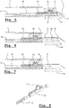
- FIG 1 a schematic representation is shown of an open roof construction with a rollo assembly, intended for use in a vehicle, with a roof opening 1 defined in a stationary roof part 2.
- a movable panel 3 is provided intended for closing and at least partially opening said roof opening 1 in a manner known per se.
- the rollo assembly comprises a rotatable winding shaft 4, a rollo screen 5 of which a rear end can be wound on or off said winding shaft and of which an opposite forward end is provided with an operating beam 6.
- opposite stationary guide channels 7 are provided at opposite longitudinal sides of and below the roof opening 1 for in a longitudinal direction L guiding opposite side edges of the rollo screen 5 and opposite ends of the operating beam 6.
- Drive cables 8 driven by, for example, an electric motor 9 (or alternatively manually by a hand crank) extend in said guide channels 7 and are provided with connecting members 10 for drivingly engaging the operating beam 6 (more specifically counter connecting members 11 provided at opposite ends of the operating beam 6).
- the winding shaft 4, operating beam 6 and rollo screen 5 are combined into a detachable unit 12 (schematically indicated by a broken line) which, when the rollo screen 5 is substantially fully wound onto the winding shaft 4 and the drive cables 8 assume a position in which the connecting members 10 at least partially protrude from a longitudinal (here rear) end of the guide channels 7 facing the detachable unit 12 (as represented in figure 1 ), can be moved in a substantially vertical direction V substantially perpendicularly to said longitudinal direction L relative to said stationary guide channels 7 for connecting or disconnecting the counter connecting members 11 of the operating beam 6 to or from the connecting members 10 of the drive cables 8.
- the connecting members 10 define projections 13, while the counter connecting members 11 are shaped as recesses for receiving said projections 13.
- the connecting members 10 likewise may define recesses while the counter connecting members 11 define projections.
- other mating members or provisions for connecting these parts are conceivable.
- the rollo assembly further comprises supporting means for maintaining the connecting members 10 of the drive cables 8, when maximally protruding from said longitudinal end of the guide channels 7 as illustrated in figure 1 , in a well-defined position.
- Such supporting means may comprise at least one part 14, preferably of the stationary roof part 2 of the vehicle for supporting the connecting members 10 in said vertical direction V.
- Said at least one part 14 of the vehicle can be a transverse beam (in the present embodiment a rear beam) which defines part of the (boundary of the) roof opening 1. But also, for example, a middle beam is conceivable.
- Said supporting means further may comprise abutment members 15 for defining the longitudinal position of the connecting members 10 when maximally protruding from said longitudinal end of the guide channels 7 ( figure 1 ).
- abutment members 15 may be provided on said at least one part 14 of the stationary roof part 2 of the vehicle, but it also is conceivable that these abutment members 15 are attached to, or are part of another part of the vehicle.
- the connecting member 10 in the illustrated embodiment has such a length that, when maximally protruding from its guide channel 7, part of the connecting member still is housed in the respective guide channel 7. Further, referring to figure 4 , said part of the connecting member 10 and the guide channel 7 define such a tight fit that a rotation of the connecting member around a longitudinal direction as defined by the respective drive cable 8 is substantially prevented.
- the part 14, the abutment member 15 and the discussed tight fit between the connecting member 10 and guide channel 7 assure that the position and orientation of the connecting member 10 are maintained during a connecting operation as described below.
- each connecting member 10 in a limited sense is slidable in the longitudinal direction L relative to the respective drive cable 8.
- the drive cable 8 carries a base member 16 fixed thereto and the connecting member 10 is shaped as a slide member which can slide on said base member 16 .
- the base member 16 comprises a stop 17 which defines the outermost (rearmost) position of the connecting member 10 as illustrated in figure 5 . In this position the connecting operation has started and has proceeded until the connecting member 10 (or its projection 13) and counter connecting member (recess) 11 of the operating beam 6 have been engaged.
- the connecting member (slide) 10 is slid over the base member 16 in a direction (further) into the guide channel 7 without moving the drive cable ( figure 6 ). Thus any activation of the drive cable 8 can be avoided at this stage.
- winding shaft 4 will be spring-loaded for winding on the rollo screen 5 and as a result the connecting member 10 will be kept in engagement with the stop 17 during a movement of the drive cable 8 and the rollo screen 5.
- FIG 8 an alternative embodiment is illustrated in which the connecting member 10 is directly slidably connected to/mounted on the drive cable 8 without the use of a base member.
- FIG. 9 yet another embodiment is illustrated which also shows a connecting member 10 which is slidable on a base member 16.
- the base member 16 in a position in which the connecting member 10 at least partially protrudes from a longitudinal end of the guide channel 7 facing the detachable unit 12 (as illustrated in figure 9 ) is housed completely within the guide channel without protruding from said longitudinal end.
- Such an embodiment allows to mount the detachable unit in the following manner: firstly the operating beam 6 (which, as discussed above, is provided with the counter connecting members 11) is lowered such that its counter connecting members 11 engage the connecting members 10 (as represented in figure 9 as a movement from position 6' to position 6).
- the winding shaft 4 is kept stationary (this basically may apply for other parts of the unit 12 too, however with the exception of the operating beam 6).
- the connecting member 10 is slid over the base member 16 into the guide channel 7 (reaching the position indicated in figure 10 ), where after the winding shaft 4 is moved towards the guide channel 7 (as represented in figure 10 as the movement from position 4' to position 4).
- the winding shaft is lowered to its final position (movement from position 4' to position 4 in figure 11 ).
- the rollo assembly is ready for use, meaning that the base member 16 can move to the left, which eventually will lead to a corresponding movement of the connecting member 10 and thus, via the counter connecting member 11 of the operating beam 6, of the rollo screen 5.
- part supporting the connecting member also may be part of another vehicle part and is not limited to being part of the stationary roof part.
Landscapes
- Engineering & Computer Science (AREA)
- Mechanical Engineering (AREA)
- Operating, Guiding And Securing Of Roll- Type Closing Members (AREA)
Claims (14)
- Rolloanordnung, die vorgesehen ist für eine Verwendung in einer offenen Dachkonstruktion für ein Fahrzeug mit einer Dachöffnung (1), die in einem stationären Dachteil (2) definiert ist, aufweisend eine drehbare Wickelwelle (4), einen Rolloschirm (5), von dem ein hinteres Ende auf die oder von der Wickelwelle gewickelt werden kann und von dem ein gegenüberliegendes vorderes Ende bereitgestellt ist mit einem Arbeitsträger (6), gegenüberliegenden stationären Führungskanälen (7), um gegenüberliegende Seitenränder des Rolloschirms und gegenüberliegende Enden des Arbeitsträgers in einer Längsrichtung zu führen, und Antriebskabeln (8), die sich in die Führungskanäle erstrecken und mit Verbindungselementen (10) bereitgestellt sind, um treibend im Eingriff mit jeweiligen Gegenverbindungselementen (11) zu stehen, die an gegenüberliegenden Enden des Arbeitsträgers bereitgestellt sind, wobei die Wickelwelle (4), der Arbeitsträger (6) und der Rolloschirm (5) kombiniert sind zu einer abnehmbaren Einheit (12), die, wenn der Rolloschirm im Wesentlichen vollständig auf der Wickelwelle aufgewickelt ist und die Antriebskabel eine Position einnehmen, in der die Verbindungselemente zumindest teilweise von einem Längsende der Führungskanäle, das der abnehmbaren Einheit zugewandt ist, vorstehen, in eine im Wesentlichen vertikale Richtung bewegt werden kann, im Wesentlichen senkrecht zu der Längsrichtung relativ zu den stationären Führungskanälen, um die Gegenverbindungselemente des Arbeitsträgers mit oder von den Verbindungselementen der Antriebskabel zu verbinden oder zu trennen, wobei die Rolloanordnung ferner Stützmittel (14, 15) aufweist, um die Verbindungselemente (10) der Antriebskabel (8) bei maximalem Vorstehen von dem Längsende der Führungskanäle (7) in einer wohldefinierten Position zu halten, dadurch gekennzeichnet, dass die Stützmittel (14, 15) von den Führungskanälen verschiedene Mittel sind.
- Rolloanordnung nach Anspruch 1, wobei die Stützmittel mindestens ein Teil (14), vorzugsweise des stationären Dachteils (2), des Fahrzeugs aufweisen, um die Verbindungselemente (10) in der vertikalen Richtung zu stützen.
- Rolloanordnung nach Anspruch 2, wobei das mindestens eine Teil (14) des Fahrzeugs ein Querträger ist, der vorzugsweise einen Teil der Dachöffnung (1) definiert.
- Rolloanordnung nach Anspruch 3, wobei der Querträger ein hinterer Träger der Dachöffnung (1) ist.
- Rolloanordnung nach irgendeinem der vorherigen Ansprüche, wobei die Stützmittel Widerlagerelemente (15) aufweisen, um die Längsposition der Verbindungselemente (10) bei maximalem Vorstehen von dem Längsende der Führungskanäle (7) zu definieren.
- Rolloanordnung nach Anspruch 5, wobei die Widerlagerelemente (15) an mindestens einem Teil (14), vorzugsweise des stationären Dachteils (2), des Fahrzeugs bereitgestellt sind.
- Rolloanordnung nach Anspruch 6, wobei das mindestens eine Teil (14) des Fahrzeugs ein Querträger ist, der vorzugsweise einen Teil der Dachöffnung (1) definiert und vorzugsweise ein hinterer Träger der Dachöffnung (1) ist.
- Rolloanordnung nach irgendeinem der vorherigen Ansprüche, wobei jedes Verbindungselement (10) eine derartige Länge aufweist, dass bei maximalem Vorstehen vom Führungskanal (7) ein Teil des Verbindungselements noch im jeweiligen Führungskanal untergebracht ist, und wobei der Teil des Verbindungselements und der Führungskanal eine derart feste Passung definieren, dass eine Rotation des Verbindungselements um die Längsrichtung, wie vom jeweiligen Antriebskabel (8) definiert, im Wesentlichen verhindert wird.
- Rolloanordnung nach irgendeinem der vorherigen Ansprüche, wobei jedes Verbindungselement (10) in der Längsrichtung in einer beschränkten Weise relativ zum jeweiligen Antriebskabel (8) verschiebbar ist.
- Rolloanordnung nach Anspruch 9, wobei das Verbindungselement (10) direkt verschiebbar mit dem Antriebskabel (8) verbunden ist.
- Rolloanordnung nach Anspruch 9, wobei das Antriebskabel (8) ein daran befestigtes Basiselement (16) trägt und wobei das Verbindungselement (10) durch ein Verschiebeelement definiert ist, das an dem Basiselement verschiebbar ist.
- Rolloanordnung nach Anspruch 11, wobei das Basiselement (16) in einer Position, in der das Verbindungselement (10) mindestens teilweise von einem der abnehmbaren Einheit (12) zugewandten Längsende des Führungskanals (7) vorsteht, vollständig innerhalb des Führungskanals untergebracht ist, ohne vom Längsende vorzustehen.
- Rolloanordnung nach irgendeinem der vorherigen Ansprüche, wobei jedes Verbindungselement (10) ein vorstehendes Element (13) definiert, wohingegen jedes Gegenverbindungselement (11) des Arbeitsträgers (6) eine korrespondierende Aussparung definiert, um ein Verbindungselement aufzunehmen.
- Offene Dachkonstruktion für ein Fahrzeug, aufweisend eine Dachöffnung (1), die in einem stationären Dachteil (2) bereitgestellt ist, eine bewegliche Platte (3), die zum Schließen und zumindest zum teilweisen Öffnen der Dachöffnung vorgesehen ist, und mit einer Rolloanordnung nach irgendeinem der vorherigen Ansprüche, die unter der Dachöffnung angeordnet ist.
Priority Applications (3)
| Application Number | Priority Date | Filing Date | Title |
|---|---|---|---|
| EP18196624.3A EP3628520B1 (de) | 2018-09-25 | 2018-09-25 | Rolloanordnung und damit ausgestattete offene dachkonstruktion |
| CN201910807822.3A CN110936795B (zh) | 2018-09-25 | 2019-08-29 | 卷帘组件以及设置有其的敞开式车顶构造 |
| US16/579,152 US11390148B2 (en) | 2018-09-25 | 2019-09-23 | Rollo assembly and open roof construction provided therewith |
Applications Claiming Priority (1)
| Application Number | Priority Date | Filing Date | Title |
|---|---|---|---|
| EP18196624.3A EP3628520B1 (de) | 2018-09-25 | 2018-09-25 | Rolloanordnung und damit ausgestattete offene dachkonstruktion |
Publications (2)
| Publication Number | Publication Date |
|---|---|
| EP3628520A1 EP3628520A1 (de) | 2020-04-01 |
| EP3628520B1 true EP3628520B1 (de) | 2021-05-26 |
Family
ID=63683785
Family Applications (1)
| Application Number | Title | Priority Date | Filing Date |
|---|---|---|---|
| EP18196624.3A Active EP3628520B1 (de) | 2018-09-25 | 2018-09-25 | Rolloanordnung und damit ausgestattete offene dachkonstruktion |
Country Status (3)
| Country | Link |
|---|---|
| US (1) | US11390148B2 (de) |
| EP (1) | EP3628520B1 (de) |
| CN (1) | CN110936795B (de) |
Family Cites Families (9)
| Publication number | Priority date | Publication date | Assignee | Title |
|---|---|---|---|---|
| US4159144A (en) | 1977-09-01 | 1979-06-26 | General Motors Corporation | Vehicle body sunroof |
| JPS5823248B2 (ja) | 1979-01-22 | 1983-05-13 | マツダ株式会社 | 自動車のスライデイングル−フにおけるガイドレ−ル構造 |
| DE19927234C1 (de) | 1999-06-15 | 2000-07-27 | Webasto Vehicle Sys Int Gmbh | Führungsschiene |
| DE102012019078A1 (de) | 2012-09-27 | 2013-03-21 | Daimler Ag | Dachmodul für ein Fahrzeugdach eines Personenkraftwagens sowie Anordnung eines solchen Dachmoduls an einem Fahrzeugdach |
| DE102014005476A1 (de) * | 2014-04-15 | 2015-10-15 | Webasto SE | Rollovorrichtung an einem Fahrzeugdach |
| WO2016107650A1 (en) * | 2014-12-30 | 2016-07-07 | Inalfa Roof Systems Group B.V. | Rollo assembly and open roof construction for a vehicle provided therewith |
| DE102015109862B4 (de) | 2015-06-19 | 2025-04-10 | Webasto SE | Fahrzeugdach mit Rolloanordnung |
| EP3176016B1 (de) * | 2015-12-03 | 2019-04-03 | Inalfa Roof Systems Group B.V. | Rolloanordnung |
| US10053909B2 (en) * | 2016-08-25 | 2018-08-21 | J. Paxton Enterprises, Inc. | Triple-shade roller blind |
-
2018
- 2018-09-25 EP EP18196624.3A patent/EP3628520B1/de active Active
-
2019
- 2019-08-29 CN CN201910807822.3A patent/CN110936795B/zh active Active
- 2019-09-23 US US16/579,152 patent/US11390148B2/en active Active
Also Published As
| Publication number | Publication date |
|---|---|
| CN110936795B (zh) | 2023-10-31 |
| US20200094659A1 (en) | 2020-03-26 |
| EP3628520A1 (de) | 2020-04-01 |
| US11390148B2 (en) | 2022-07-19 |
| CN110936795A (zh) | 2020-03-31 |
Similar Documents
| Publication | Publication Date | Title |
|---|---|---|
| US6119402A (en) | Power sliding rear window | |
| CA1045653A (en) | Sliding roof for automobiles | |
| US4081926A (en) | Sunroof | |
| US10569622B2 (en) | Vehicle roof having a roller blind arrangement | |
| US4671565A (en) | Cable guide for sliding roofs of motor vehicles | |
| EP2151339B1 (de) | Sonnenblendeanordnung und damit ausgestattete offene Dachkonstruktion | |
| US4531777A (en) | Motor vehicle roof arrangement of the type interchangeably driveable by both motor and crank drives | |
| EP3176016B1 (de) | Rolloanordnung | |
| EP2883727B1 (de) | Antriebsmechanismus und damit ausgestattete öffnungsfähige dachkonstruktion | |
| EP3100883B1 (de) | Rolloanordnung und offene dachkonstruktion für ein damit ausgestattetes fahrzeug | |
| US7665793B2 (en) | Roller blind system for a vehicle roof | |
| JP7131025B2 (ja) | サンルーフ装置の製造方法 | |
| DE10110012A1 (de) | Fahrzeugdach mit zwei bewegbaren Deckeln | |
| EP3628520B1 (de) | Rolloanordnung und damit ausgestattete offene dachkonstruktion | |
| EP2845759B1 (de) | Schiebedachvorrichtung für ein fahrzeug | |
| US20200290437A1 (en) | Shade apparatus for use with vehicles | |
| EP0754583B1 (de) | Schiebehebedach und ein mit einem solchen Schiebehebedach ausgerüstetes Kraftfahrzeug | |
| US8800635B2 (en) | Lateral guide for shading roller blind, and shading roller blind for motor vehicles | |
| US20200276892A1 (en) | Sunroof apparatus | |
| EP2845760B1 (de) | Schiebedachvorrichtung für ein Fahrzeug | |
| US4069616A (en) | Window regulator | |
| JP5146773B2 (ja) | 自動車用サンシェード装置 | |
| EP2062766B1 (de) | Sonnenschutzanordnung mit zwei Vorhängen | |
| JP6816502B2 (ja) | 車両用スライドドアモジュール | |
| CN109291772B (zh) | 用于车辆的开放式车顶结构 |
Legal Events
| Date | Code | Title | Description |
|---|---|---|---|
| PUAI | Public reference made under article 153(3) epc to a published international application that has entered the european phase |
Free format text: ORIGINAL CODE: 0009012 |
|
| STAA | Information on the status of an ep patent application or granted ep patent |
Free format text: STATUS: THE APPLICATION HAS BEEN PUBLISHED |
|
| AK | Designated contracting states |
Kind code of ref document: A1 Designated state(s): AL AT BE BG CH CY CZ DE DK EE ES FI FR GB GR HR HU IE IS IT LI LT LU LV MC MK MT NL NO PL PT RO RS SE SI SK SM TR |
|
| AX | Request for extension of the european patent |
Extension state: BA ME |
|
| STAA | Information on the status of an ep patent application or granted ep patent |
Free format text: STATUS: REQUEST FOR EXAMINATION WAS MADE |
|
| 17P | Request for examination filed |
Effective date: 20200409 |
|
| RBV | Designated contracting states (corrected) |
Designated state(s): AL AT BE BG CH CY CZ DE DK EE ES FI FR GB GR HR HU IE IS IT LI LT LU LV MC MK MT NL NO PL PT RO RS SE SI SK SM TR |
|
| GRAP | Despatch of communication of intention to grant a patent |
Free format text: ORIGINAL CODE: EPIDOSNIGR1 |
|
| STAA | Information on the status of an ep patent application or granted ep patent |
Free format text: STATUS: GRANT OF PATENT IS INTENDED |
|
| RIC1 | Information provided on ipc code assigned before grant |
Ipc: B60J 7/00 20060101AFI20201210BHEP |
|
| INTG | Intention to grant announced |
Effective date: 20210113 |
|
| GRAS | Grant fee paid |
Free format text: ORIGINAL CODE: EPIDOSNIGR3 |
|
| GRAA | (expected) grant |
Free format text: ORIGINAL CODE: 0009210 |
|
| STAA | Information on the status of an ep patent application or granted ep patent |
Free format text: STATUS: THE PATENT HAS BEEN GRANTED |
|
| AK | Designated contracting states |
Kind code of ref document: B1 Designated state(s): AL AT BE BG CH CY CZ DE DK EE ES FI FR GB GR HR HU IE IS IT LI LT LU LV MC MK MT NL NO PL PT RO RS SE SI SK SM TR |
|
| REG | Reference to a national code |
Ref country code: GB Ref legal event code: FG4D |
|
| REG | Reference to a national code |
Ref country code: CH Ref legal event code: EP |
|
| REG | Reference to a national code |
Ref country code: AT Ref legal event code: REF Ref document number: 1395864 Country of ref document: AT Kind code of ref document: T Effective date: 20210615 |
|
| REG | Reference to a national code |
Ref country code: DE Ref legal event code: R096 Ref document number: 602018017581 Country of ref document: DE |
|
| REG | Reference to a national code |
Ref country code: IE Ref legal event code: FG4D |
|
| REG | Reference to a national code |
Ref country code: LT Ref legal event code: MG9D |
|
| REG | Reference to a national code |
Ref country code: AT Ref legal event code: MK05 Ref document number: 1395864 Country of ref document: AT Kind code of ref document: T Effective date: 20210526 |
|
| PG25 | Lapsed in a contracting state [announced via postgrant information from national office to epo] |
Ref country code: FI Free format text: LAPSE BECAUSE OF FAILURE TO SUBMIT A TRANSLATION OF THE DESCRIPTION OR TO PAY THE FEE WITHIN THE PRESCRIBED TIME-LIMIT Effective date: 20210526 Ref country code: LT Free format text: LAPSE BECAUSE OF FAILURE TO SUBMIT A TRANSLATION OF THE DESCRIPTION OR TO PAY THE FEE WITHIN THE PRESCRIBED TIME-LIMIT Effective date: 20210526 Ref country code: HR Free format text: LAPSE BECAUSE OF FAILURE TO SUBMIT A TRANSLATION OF THE DESCRIPTION OR TO PAY THE FEE WITHIN THE PRESCRIBED TIME-LIMIT Effective date: 20210526 Ref country code: BG Free format text: LAPSE BECAUSE OF FAILURE TO SUBMIT A TRANSLATION OF THE DESCRIPTION OR TO PAY THE FEE WITHIN THE PRESCRIBED TIME-LIMIT Effective date: 20210826 Ref country code: AT Free format text: LAPSE BECAUSE OF FAILURE TO SUBMIT A TRANSLATION OF THE DESCRIPTION OR TO PAY THE FEE WITHIN THE PRESCRIBED TIME-LIMIT Effective date: 20210526 |
|
| REG | Reference to a national code |
Ref country code: NL Ref legal event code: MP Effective date: 20210526 |
|
| PG25 | Lapsed in a contracting state [announced via postgrant information from national office to epo] |
Ref country code: IS Free format text: LAPSE BECAUSE OF FAILURE TO SUBMIT A TRANSLATION OF THE DESCRIPTION OR TO PAY THE FEE WITHIN THE PRESCRIBED TIME-LIMIT Effective date: 20210926 Ref country code: GR Free format text: LAPSE BECAUSE OF FAILURE TO SUBMIT A TRANSLATION OF THE DESCRIPTION OR TO PAY THE FEE WITHIN THE PRESCRIBED TIME-LIMIT Effective date: 20210827 Ref country code: RS Free format text: LAPSE BECAUSE OF FAILURE TO SUBMIT A TRANSLATION OF THE DESCRIPTION OR TO PAY THE FEE WITHIN THE PRESCRIBED TIME-LIMIT Effective date: 20210526 Ref country code: SE Free format text: LAPSE BECAUSE OF FAILURE TO SUBMIT A TRANSLATION OF THE DESCRIPTION OR TO PAY THE FEE WITHIN THE PRESCRIBED TIME-LIMIT Effective date: 20210526 Ref country code: NO Free format text: LAPSE BECAUSE OF FAILURE TO SUBMIT A TRANSLATION OF THE DESCRIPTION OR TO PAY THE FEE WITHIN THE PRESCRIBED TIME-LIMIT Effective date: 20210826 Ref country code: LV Free format text: LAPSE BECAUSE OF FAILURE TO SUBMIT A TRANSLATION OF THE DESCRIPTION OR TO PAY THE FEE WITHIN THE PRESCRIBED TIME-LIMIT Effective date: 20210526 Ref country code: PT Free format text: LAPSE BECAUSE OF FAILURE TO SUBMIT A TRANSLATION OF THE DESCRIPTION OR TO PAY THE FEE WITHIN THE PRESCRIBED TIME-LIMIT Effective date: 20210927 Ref country code: PL Free format text: LAPSE BECAUSE OF FAILURE TO SUBMIT A TRANSLATION OF THE DESCRIPTION OR TO PAY THE FEE WITHIN THE PRESCRIBED TIME-LIMIT Effective date: 20210526 |
|
| PG25 | Lapsed in a contracting state [announced via postgrant information from national office to epo] |
Ref country code: NL Free format text: LAPSE BECAUSE OF FAILURE TO SUBMIT A TRANSLATION OF THE DESCRIPTION OR TO PAY THE FEE WITHIN THE PRESCRIBED TIME-LIMIT Effective date: 20210526 |
|
| PG25 | Lapsed in a contracting state [announced via postgrant information from national office to epo] |
Ref country code: SK Free format text: LAPSE BECAUSE OF FAILURE TO SUBMIT A TRANSLATION OF THE DESCRIPTION OR TO PAY THE FEE WITHIN THE PRESCRIBED TIME-LIMIT Effective date: 20210526 Ref country code: SM Free format text: LAPSE BECAUSE OF FAILURE TO SUBMIT A TRANSLATION OF THE DESCRIPTION OR TO PAY THE FEE WITHIN THE PRESCRIBED TIME-LIMIT Effective date: 20210526 Ref country code: EE Free format text: LAPSE BECAUSE OF FAILURE TO SUBMIT A TRANSLATION OF THE DESCRIPTION OR TO PAY THE FEE WITHIN THE PRESCRIBED TIME-LIMIT Effective date: 20210526 Ref country code: ES Free format text: LAPSE BECAUSE OF FAILURE TO SUBMIT A TRANSLATION OF THE DESCRIPTION OR TO PAY THE FEE WITHIN THE PRESCRIBED TIME-LIMIT Effective date: 20210526 Ref country code: DK Free format text: LAPSE BECAUSE OF FAILURE TO SUBMIT A TRANSLATION OF THE DESCRIPTION OR TO PAY THE FEE WITHIN THE PRESCRIBED TIME-LIMIT Effective date: 20210526 Ref country code: CZ Free format text: LAPSE BECAUSE OF FAILURE TO SUBMIT A TRANSLATION OF THE DESCRIPTION OR TO PAY THE FEE WITHIN THE PRESCRIBED TIME-LIMIT Effective date: 20210526 Ref country code: RO Free format text: LAPSE BECAUSE OF FAILURE TO SUBMIT A TRANSLATION OF THE DESCRIPTION OR TO PAY THE FEE WITHIN THE PRESCRIBED TIME-LIMIT Effective date: 20210526 |
|
| REG | Reference to a national code |
Ref country code: DE Ref legal event code: R097 Ref document number: 602018017581 Country of ref document: DE |
|
| PLBE | No opposition filed within time limit |
Free format text: ORIGINAL CODE: 0009261 |
|
| STAA | Information on the status of an ep patent application or granted ep patent |
Free format text: STATUS: NO OPPOSITION FILED WITHIN TIME LIMIT |
|
| REG | Reference to a national code |
Ref country code: CH Ref legal event code: PL |
|
| 26N | No opposition filed |
Effective date: 20220301 |
|
| REG | Reference to a national code |
Ref country code: BE Ref legal event code: MM Effective date: 20210930 |
|
| PG25 | Lapsed in a contracting state [announced via postgrant information from national office to epo] |
Ref country code: IS Free format text: LAPSE BECAUSE OF FAILURE TO SUBMIT A TRANSLATION OF THE DESCRIPTION OR TO PAY THE FEE WITHIN THE PRESCRIBED TIME-LIMIT Effective date: 20210926 Ref country code: MC Free format text: LAPSE BECAUSE OF FAILURE TO SUBMIT A TRANSLATION OF THE DESCRIPTION OR TO PAY THE FEE WITHIN THE PRESCRIBED TIME-LIMIT Effective date: 20210526 Ref country code: AL Free format text: LAPSE BECAUSE OF FAILURE TO SUBMIT A TRANSLATION OF THE DESCRIPTION OR TO PAY THE FEE WITHIN THE PRESCRIBED TIME-LIMIT Effective date: 20210526 |
|
| PG25 | Lapsed in a contracting state [announced via postgrant information from national office to epo] |
Ref country code: LU Free format text: LAPSE BECAUSE OF NON-PAYMENT OF DUE FEES Effective date: 20210925 Ref country code: IT Free format text: LAPSE BECAUSE OF FAILURE TO SUBMIT A TRANSLATION OF THE DESCRIPTION OR TO PAY THE FEE WITHIN THE PRESCRIBED TIME-LIMIT Effective date: 20210526 Ref country code: IE Free format text: LAPSE BECAUSE OF NON-PAYMENT OF DUE FEES Effective date: 20210925 Ref country code: BE Free format text: LAPSE BECAUSE OF NON-PAYMENT OF DUE FEES Effective date: 20210930 |
|
| PG25 | Lapsed in a contracting state [announced via postgrant information from national office to epo] |
Ref country code: LI Free format text: LAPSE BECAUSE OF NON-PAYMENT OF DUE FEES Effective date: 20210930 Ref country code: CH Free format text: LAPSE BECAUSE OF NON-PAYMENT OF DUE FEES Effective date: 20210930 |
|
| GBPC | Gb: european patent ceased through non-payment of renewal fee |
Effective date: 20220925 |
|
| PG25 | Lapsed in a contracting state [announced via postgrant information from national office to epo] |
Ref country code: CY Free format text: LAPSE BECAUSE OF FAILURE TO SUBMIT A TRANSLATION OF THE DESCRIPTION OR TO PAY THE FEE WITHIN THE PRESCRIBED TIME-LIMIT Effective date: 20210526 |
|
| PG25 | Lapsed in a contracting state [announced via postgrant information from national office to epo] |
Ref country code: HU Free format text: LAPSE BECAUSE OF FAILURE TO SUBMIT A TRANSLATION OF THE DESCRIPTION OR TO PAY THE FEE WITHIN THE PRESCRIBED TIME-LIMIT; INVALID AB INITIO Effective date: 20180925 |
|
| PG25 | Lapsed in a contracting state [announced via postgrant information from national office to epo] |
Ref country code: GB Free format text: LAPSE BECAUSE OF NON-PAYMENT OF DUE FEES Effective date: 20220925 |
|
| PG25 | Lapsed in a contracting state [announced via postgrant information from national office to epo] |
Ref country code: MK Free format text: LAPSE BECAUSE OF FAILURE TO SUBMIT A TRANSLATION OF THE DESCRIPTION OR TO PAY THE FEE WITHIN THE PRESCRIBED TIME-LIMIT Effective date: 20210526 |
|
| PG25 | Lapsed in a contracting state [announced via postgrant information from national office to epo] |
Ref country code: MT Free format text: LAPSE BECAUSE OF FAILURE TO SUBMIT A TRANSLATION OF THE DESCRIPTION OR TO PAY THE FEE WITHIN THE PRESCRIBED TIME-LIMIT Effective date: 20210526 |
|
| PGFP | Annual fee paid to national office [announced via postgrant information from national office to epo] |
Ref country code: DE Payment date: 20250929 Year of fee payment: 8 |
|
| PGFP | Annual fee paid to national office [announced via postgrant information from national office to epo] |
Ref country code: FR Payment date: 20250925 Year of fee payment: 8 |
|
| PG25 | Lapsed in a contracting state [announced via postgrant information from national office to epo] |
Ref country code: TR Free format text: LAPSE BECAUSE OF FAILURE TO SUBMIT A TRANSLATION OF THE DESCRIPTION OR TO PAY THE FEE WITHIN THE PRESCRIBED TIME-LIMIT Effective date: 20210526 |