EP3628558A1 - Amplificateur de force de freinage électromécanique - Google Patents
Amplificateur de force de freinage électromécanique Download PDFInfo
- Publication number
- EP3628558A1 EP3628558A1 EP19203577.2A EP19203577A EP3628558A1 EP 3628558 A1 EP3628558 A1 EP 3628558A1 EP 19203577 A EP19203577 A EP 19203577A EP 3628558 A1 EP3628558 A1 EP 3628558A1
- Authority
- EP
- European Patent Office
- Prior art keywords
- gear
- brake booster
- transmission
- electromechanical brake
- gears
- Prior art date
- Legal status (The legal status is an assumption and is not a legal conclusion. Google has not performed a legal analysis and makes no representation as to the accuracy of the status listed.)
- Granted
Links
Images
Classifications
-
- B—PERFORMING OPERATIONS; TRANSPORTING
- B60—VEHICLES IN GENERAL
- B60T—VEHICLE BRAKE CONTROL SYSTEMS OR PARTS THEREOF; BRAKE CONTROL SYSTEMS OR PARTS THEREOF, IN GENERAL; ARRANGEMENT OF BRAKING ELEMENTS ON VEHICLES IN GENERAL; PORTABLE DEVICES FOR PREVENTING UNWANTED MOVEMENT OF VEHICLES; VEHICLE MODIFICATIONS TO FACILITATE COOLING OF BRAKES
- B60T13/00—Transmitting braking action from initiating means to ultimate brake actuator with power assistance or drive; Brake systems incorporating such transmitting means, e.g. air-pressure brake systems
- B60T13/74—Transmitting braking action from initiating means to ultimate brake actuator with power assistance or drive; Brake systems incorporating such transmitting means, e.g. air-pressure brake systems with electrical assistance or drive
- B60T13/745—Transmitting braking action from initiating means to ultimate brake actuator with power assistance or drive; Brake systems incorporating such transmitting means, e.g. air-pressure brake systems with electrical assistance or drive acting on a hydraulic system, e.g. a master cylinder
-
- F—MECHANICAL ENGINEERING; LIGHTING; HEATING; WEAPONS; BLASTING
- F16—ENGINEERING ELEMENTS AND UNITS; GENERAL MEASURES FOR PRODUCING AND MAINTAINING EFFECTIVE FUNCTIONING OF MACHINES OR INSTALLATIONS; THERMAL INSULATION IN GENERAL
- F16H—GEARING
- F16H1/00—Toothed gearings for conveying rotary motion
- F16H1/02—Toothed gearings for conveying rotary motion without gears having orbital motion
- F16H1/20—Toothed gearings for conveying rotary motion without gears having orbital motion involving more than two intermeshing members
- F16H1/22—Toothed gearings for conveying rotary motion without gears having orbital motion involving more than two intermeshing members with a plurality of driving or driven shafts; with arrangements for dividing torque between two or more intermediate shafts
-
- F—MECHANICAL ENGINEERING; LIGHTING; HEATING; WEAPONS; BLASTING
- F16—ENGINEERING ELEMENTS AND UNITS; GENERAL MEASURES FOR PRODUCING AND MAINTAINING EFFECTIVE FUNCTIONING OF MACHINES OR INSTALLATIONS; THERMAL INSULATION IN GENERAL
- F16H—GEARING
- F16H19/00—Gearings comprising essentially only toothed gears or friction members and not capable of conveying indefinitely-continuing rotary motion
-
- F—MECHANICAL ENGINEERING; LIGHTING; HEATING; WEAPONS; BLASTING
- F16—ENGINEERING ELEMENTS AND UNITS; GENERAL MEASURES FOR PRODUCING AND MAINTAINING EFFECTIVE FUNCTIONING OF MACHINES OR INSTALLATIONS; THERMAL INSULATION IN GENERAL
- F16H—GEARING
- F16H35/00—Gearings or mechanisms with other special functional features
- F16H35/02—Gearings or mechanisms with other special functional features for conveying rotary motion with cyclically varying velocity ratio
-
- F—MECHANICAL ENGINEERING; LIGHTING; HEATING; WEAPONS; BLASTING
- F16—ENGINEERING ELEMENTS AND UNITS; GENERAL MEASURES FOR PRODUCING AND MAINTAINING EFFECTIVE FUNCTIONING OF MACHINES OR INSTALLATIONS; THERMAL INSULATION IN GENERAL
- F16H—GEARING
- F16H1/00—Toothed gearings for conveying rotary motion
- F16H1/02—Toothed gearings for conveying rotary motion without gears having orbital motion
- F16H1/04—Toothed gearings for conveying rotary motion without gears having orbital motion involving only two intermeshing members
- F16H1/12—Toothed gearings for conveying rotary motion without gears having orbital motion involving only two intermeshing members with non-parallel axes
- F16H1/16—Toothed gearings for conveying rotary motion without gears having orbital motion involving only two intermeshing members with non-parallel axes comprising worm and worm-wheel
-
- F—MECHANICAL ENGINEERING; LIGHTING; HEATING; WEAPONS; BLASTING
- F16—ENGINEERING ELEMENTS AND UNITS; GENERAL MEASURES FOR PRODUCING AND MAINTAINING EFFECTIVE FUNCTIONING OF MACHINES OR INSTALLATIONS; THERMAL INSULATION IN GENERAL
- F16H—GEARING
- F16H19/00—Gearings comprising essentially only toothed gears or friction members and not capable of conveying indefinitely-continuing rotary motion
- F16H19/02—Gearings comprising essentially only toothed gears or friction members and not capable of conveying indefinitely-continuing rotary motion for interconverting rotary or oscillating motion and reciprocating motion
- F16H19/04—Gearings comprising essentially only toothed gears or friction members and not capable of conveying indefinitely-continuing rotary motion for interconverting rotary or oscillating motion and reciprocating motion comprising a rack
-
- F—MECHANICAL ENGINEERING; LIGHTING; HEATING; WEAPONS; BLASTING
- F16—ENGINEERING ELEMENTS AND UNITS; GENERAL MEASURES FOR PRODUCING AND MAINTAINING EFFECTIVE FUNCTIONING OF MACHINES OR INSTALLATIONS; THERMAL INSULATION IN GENERAL
- F16H—GEARING
- F16H35/00—Gearings or mechanisms with other special functional features
- F16H2035/003—Gearings comprising pulleys or toothed members of non-circular shape, e.g. elliptical gears
Definitions
- the invention relates to an electromechanical brake booster with the features of the preamble of claim 1.
- the disclosure DE 103 27 553 A1 discloses an electromechanical brake booster with a hollow shaft electric motor, the hollow rotor of which has a spindle nut which is in engagement with a hollow spindle.
- the spindle nut and the spindle form a spindle drive or generally a screw gear, which converts a rotary drive movement of the electric motor into a translatory drive movement for actuating a hydraulic master brake cylinder.
- the spindle drive of the known electromechanical brake booster thus forms a rotation / translation conversion gear.
- the translational output movement of the hollow spindle is transmitted to a driver which is fixedly arranged on a piston rod of the brake booster.
- the piston rod is connected in an articulated manner to a brake pedal and is subjected to a muscular strength of a vehicle driver in order to actuate the brake via the brake pedal.
- the piston rod is connected to a piston of the master brake cylinder, it transfers the muscle power and the booster force of the brake booster to the piston of the master brake cylinder.
- the piston rod of the known brake booster also forms its push rod.
- the published patent application discloses another electromechanical brake booster DE 30 31 643 A1 .
- This brake booster also has an electric motor that drives a multi-plate clutch via a worm gear.
- the rotary drive movement of the Coupled electric motor The torque injected by the electric motor via the downstream worm gear depends on an axial application of the multi-plate clutch by a muscle force that is exerted by a driver to apply the brake.
- the electromechanical brake booster according to the invention with the features of claim 1 has an electric motor and a transmission which is driven by the electric motor.
- the transmission has a rotation / translation conversion transmission, which converts a rotary drive movement of the electric motor into a translational output movement for actuating a hydraulic master brake cylinder.
- Possible rotation / translation conversion gears are, for example, a rack and pinion gear, a screw gear such as a spindle drive, a ball screw gear, a roller screw drive, also in the form of a planetary roller screw drive, or a traction mechanism gear. The list is not exhaustive.
- the drive or input of the rotary / translation conversion gearbox need not necessarily be the drive or input of the gearbox as a whole, the rotary / translation conversion gearbox can be preceded by a further gearbox or a gear stage.
- a further gear or a gear stage can be connected downstream of the rotation / translation conversion gear.
- the transmission of the electromechanical brake booster according to the invention has a transfer case and a combination gear.
- the transfer case and / or the combination gear can comprise parts of the rotation / translation conversion gear.
- the transfer case distributes a transmission input to at least two transmission paths, the combining transmission unites the transmission paths again to a common transmission output.
- the gearbox input of the transfer case does not have to be the gearbox input of the transmission of the brake booster, but a gearbox or a gear stage can be connected upstream of the transfer gearbox.
- the gearbox output must also the union gearbox is not the output of the gearbox as a whole, but a further gearbox or a gear stage can be connected downstream of the union gearbox.
- the gears can be present in each gear path, each gear path preferably having the same gear, but this is not mandatory.
- the gears can form the union gear.
- An advantage of the invention is the distribution of the load of the transmission, that is to say a torque transmitted by the transmission and / or a force transmitted by the transmission, over at least two transmission paths. This reduces the load on the transmission paths, which enables, for example, the production of parts of the transmission from plastic instead of steel.
- Another advantage of the invention is the possibility of a symmetrical design and a symmetrical initiation of the translational output movement on an output element of the brake booster.
- Claim 4 provides for a multi-stage design of the transmission, for example a reduction gear is connected upstream of the rotation / translation conversion gear.
- a worm gear, a possibly multi-stage spur gear, a planetary gear, a bevel gear or a crown gear can be used as a reduction gear.
- the list is not exhaustive.
- the gears can form the transfer case and / or be present in each gear path. It also applies to a multi-stage transmission design that preferably each transmission path has the same transmission, which, however, is not essential for the invention.
- Claim 5 provides a transmission with a changing translation.
- the gear ratio decreases or a reduction increases with increasing displacement of an output element of the brake booster.
- the booster force exerted by the brake booster is greater, whereas at the beginning of a brake application, a displacement speed of the output member of the brake booster is greater for a given speed of the electric motor.
- cam gears also those with a cylinder curve, are known.
- Cam gears also include cam gears with a cam that can be driven to rotate or in particular pivot. This list is also not exhaustive.
- the division into several such transmissions in several transmission paths can be advantageous in order to reduce the load on the individual transmissions.
- the invention is explained in more detail below with reference to an embodiment shown in the drawing.
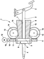
- the single figure shows a schematic and simplified axial sectional view of an electromechanical brake booster according to the invention.
- the electromechanical brake booster 1 has a piston rod 2, which is connected in an articulated manner to a brake pedal 3, which is not part of the brake booster 1, and a push rod 4.
- a hydraulic master brake cylinder not shown, can be actuated in a manner known per se, ie. H. a piston can be moved into the master brake cylinder.
- a so-called reaction disk 5 is arranged between the piston rod 2 and the pressure rod 4, via which a pressure force is transmitted from the piston rod 2 to the pressure rod 4.
- the piston of the master brake cylinder By depressing the brake pedal 3, the piston of the master brake cylinder, not shown, can be displaced into the master brake cylinder via the piston rod 2, the reaction disk 5 and the push rod 4, i. H. the master brake cylinder can be operated with muscle power in the manner described.
- the reaction disk 5 is made of rubber or a rubber-elastic plastic.
- the brake booster 1 has an amplifier body 6 with a coaxial through hole 7, in which the piston rod 2 is axially displaceably received.
- the amplifier body 6 is also axially displaceable, it tapers on its outside in the shape of a truncated cone in the direction of the push rod 4 and widens at its push rod end to a foot diameter of Truncated cone.
- the booster body 6 has a cylindrical countersink 8, in the bottom of which the through hole 7 opens and in which the reaction disk 5 lies and in which a plate-shaped foot 9 of the push rod 4 is received.
- a screw shaft 10 is arranged transversely to the amplifier body 6 and has two screws 11 rigidly connected to it or integral with it, which are located symmetrically on both sides of the amplifier body 6.
- the worm shaft 10 can be driven by an electric motor 12.
- the two worms 11 have pitches of the same size and opposite to each other. They mesh with worm gears 13 and form with these worm gears 11, 13. Due to the opposite inclinations of the worms 11 and thus due to the opposite movement of the two worm gears 11, 13, axial forces of the two worms 11 equalize when driving the worm gears 13, so that the Auger shaft 10 is free of axial force.
- a coupling 16 connects the worm shaft 10 in a rotationally fixed and axially movable manner to a motor shaft of the electric motor 12. By means of an axial displacement, the worm shaft 10 compensates for any tolerances in the gear paths, the gear paths are loaded equally.
- the worm wheels 13 are non-rotatable with spur gears 14 which are arranged opposite one another on both sides of the booster body 6.
- the spur gears 14 mesh with racks 15 of the booster body 6, which extend in the longitudinal direction of the booster body 6 in its frustoconical region. A distance between the two racks 15 decreases in the direction of the push rod 4.
- the spur gears 14 have a constant center distance from one another and from the booster body 6, they are eccentric, so that they are inclined to the axis and displacement direction of the booster body 6 of the racks 15th compensate.
- the spur gears 14 and the toothed racks 15 form rack and pinion gears 14, 15 which, due to the eccentricity of the spur gears 14 and the arrangement of the racks 15 obliquely to the direction of displacement, have changing ratios.
- the translation of the rack and pinion gear 14, 15 is smaller when the booster body 6 is displaced in the direction of the push rod 4, that is to say when the master brake cylinder (not shown) is actuated; with a displacement of the booster body 6 in the actuation direction of the master brake cylinder assumes a displacement speed of the booster body assuming a constant speed of the electric motor 12 6 from and assuming a constant driving torque of the electric motor 12 to an amplifier force of the brake booster 1.
- a straight course of the toothed racks 15 is not essential for the invention; in deviation from the embodiment shown, the toothed racks 15 can have any curvilinear course, in particular they can be rounded in a convex or concave manner.
- the shape of the spur gears 14 must be adapted to the course of the racks 15 so that the toothings always mesh.
- a variable center distance of the spur gears 14 from one another and from the booster body 6 is also conceivable.
- Racks 15 with a course parallel to the direction of displacement and concentric spur gears 14 are also possible, in which case the rack and pinion gears have a constant ratio (not shown).
- the spur gears 14 have a toothing only in the peripheral region which meshes or engages with the toothed racks 15 when they are rotated or pivoted.
- the booster force of the brake booster 1 is transmitted from the bottom of the countersink 8 of the booster body 6 via the reaction disk 5 to the foot 9 of the push rod 4.
- the reaction disc 5 adds the muscle force exerted on the piston rod 2 via the brake pedal 3 and the amplifying force exerted by the booster body 6 of the brake booster 1 and transmits the forces together as an actuating force to the foot 9 of the push rod 4.
- the two worm gears 11, 13 form a transfer case, that distributes a transmission input to two transmission paths.
- the gear input here is the worm shaft 10 or the drive torque of the electric motor 12.
- the two gear paths each comprise a worm gear 11, 13 and a rack and pinion gear 14, 15.
- the two rack and pinion gears 14, 15 form a combination gear with the booster body 6, which transmits the moments of the two Gear paths combined as an axially acting booster force on a gearbox output, namely the booster body 6. Due to the symmetrical structure and the symmetrical arrangement of the two transmission paths, both transmission paths transmit the same load, i.e. the same moments or forces, and the transmission output, namely the amplifier body 6 is acted upon symmetrically: neither a moment nor a transverse force acts on the amplifier body 6. Overall, the two worm gears 11, 13 and the two rack and pinion gears 14, 15 form a gear of the brake booster 1.
- the two transmission paths are multi-stage, namely two-stage.
- the worm gears 11, 13 form a first gear stage and the rack and pinion gears 14, 15 form a second gear stage of the gear paths.
- the worm gears 11, 13 are reduction gears, they convert a rotary drive movement into a rotary output movement.
- the rack and pinion gears 14, 15 are rotation / translation conversion gears which convert a rotary drive movement into a translational output movement.
- the rack and pinion gears 14, 15 have a changing transmission ratio.
Landscapes
- Engineering & Computer Science (AREA)
- Mechanical Engineering (AREA)
- General Engineering & Computer Science (AREA)
- Transportation (AREA)
- Gear Transmission (AREA)
- Braking Systems And Boosters (AREA)
- Transmission Devices (AREA)
- Braking Arrangements (AREA)
- Retarders (AREA)
Applications Claiming Priority (3)
| Application Number | Priority Date | Filing Date | Title |
|---|---|---|---|
| DE200910001142 DE102009001142A1 (de) | 2009-02-25 | 2009-02-25 | Elektromechanischer Bremskraftverstärker |
| PCT/EP2009/067937 WO2010097135A1 (fr) | 2009-02-25 | 2009-12-28 | Servofrein électromécanique |
| EP09796750.9A EP2401183B1 (fr) | 2009-02-25 | 2009-12-28 | Servofrein éléctroméchanique |
Related Parent Applications (2)
| Application Number | Title | Priority Date | Filing Date |
|---|---|---|---|
| EP09796750.9A Division EP2401183B1 (fr) | 2009-02-25 | 2009-12-28 | Servofrein éléctroméchanique |
| EP09796750.9A Division-Into EP2401183B1 (fr) | 2009-02-25 | 2009-12-28 | Servofrein éléctroméchanique |
Publications (2)
| Publication Number | Publication Date |
|---|---|
| EP3628558A1 true EP3628558A1 (fr) | 2020-04-01 |
| EP3628558B1 EP3628558B1 (fr) | 2023-02-22 |
Family
ID=42347680
Family Applications (2)
| Application Number | Title | Priority Date | Filing Date |
|---|---|---|---|
| EP09796750.9A Active EP2401183B1 (fr) | 2009-02-25 | 2009-12-28 | Servofrein éléctroméchanique |
| EP19203577.2A Active EP3628558B1 (fr) | 2009-02-25 | 2009-12-28 | Servofrein éléctroméchanique |
Family Applications Before (1)
| Application Number | Title | Priority Date | Filing Date |
|---|---|---|---|
| EP09796750.9A Active EP2401183B1 (fr) | 2009-02-25 | 2009-12-28 | Servofrein éléctroméchanique |
Country Status (10)
| Country | Link |
|---|---|
| US (1) | US9139186B2 (fr) |
| EP (2) | EP2401183B1 (fr) |
| JP (2) | JP5382747B2 (fr) |
| KR (1) | KR101632595B1 (fr) |
| CN (2) | CN105711576B (fr) |
| BR (1) | BRPI0924280A2 (fr) |
| DE (1) | DE102009001142A1 (fr) |
| PL (1) | PL2401183T3 (fr) |
| RU (1) | RU2533639C2 (fr) |
| WO (1) | WO2010097135A1 (fr) |
Families Citing this family (21)
| Publication number | Priority date | Publication date | Assignee | Title |
|---|---|---|---|---|
| US8464035B2 (en) * | 2009-12-18 | 2013-06-11 | Intel Corporation | Instruction for enabling a processor wait state |
| DE102010062785A1 (de) * | 2010-12-10 | 2012-06-14 | Robert Bosch Gmbh | Elektromechanischer Bremskraftverstärker mit einstellbarer nicht-linearer Unterstützungskraft |
| DE102012014361A1 (de) * | 2012-07-20 | 2014-01-23 | Volkswagen Ag | Betätigungseinrichtung für einen Hauptbremszylinder eines Kraftfahrzeugs |
| DE102012222949A1 (de) * | 2012-12-12 | 2014-06-12 | Robert Bosch Gmbh | Getriebevorrichtung und elektromotorischer Bremskraftverstärker |
| FR3005295B1 (fr) | 2013-05-03 | 2015-08-28 | Bosch Gmbh Robert | Systeme de freins a servofrein electrique |
| DE102013217443B4 (de) * | 2013-09-02 | 2025-12-11 | Robert Bosch Gmbh | Elektromechanischer Bremskraftverstärker für ein Bremssystem eines Fahrzeugs und Verfahren zum Montieren eines elektromechanischen Bremskraftverstärkers an und/oder in einem Bremssystem für ein Fahrzeug |
| FR3017173A1 (fr) * | 2014-01-31 | 2015-08-07 | Bosch Gmbh Robert | Dispositif de transmission pour commander le mouvement de translation d'un organe et systeme de freinage equipe d'un tel dispositif de transmission formant un servofrein |
| CN105523026B (zh) | 2014-10-21 | 2018-09-28 | 株式会社万都 | 集成动力制动设备 |
| DE102014226255A1 (de) * | 2014-12-17 | 2016-06-23 | Volkswagen Aktiengesellschaft | Elektromechanischer Bremskraftverstärker |
| DE102015217518A1 (de) * | 2015-09-14 | 2017-03-16 | Robert Bosch Gmbh | Elektromechanischer Bremskraftverstärker und Verfahren zur Herstellung eines elektromechanischen Bremskraftverstärkers |
| DE102015217548A1 (de) * | 2015-09-14 | 2017-03-16 | Robert Bosch Gmbh | Bremskraftverstärker und Bremseinrichtung |
| US10682996B2 (en) | 2015-09-17 | 2020-06-16 | Zf Active Safety Gmbh | Electromechanical brake force booster |
| DE102015012124A1 (de) | 2015-09-17 | 2017-03-23 | Lucas Automotive Gmbh | Elektromechanischer Bremskraftverstärker |
| DE102015012125A1 (de) * | 2015-09-17 | 2017-03-23 | Lucas Automotive Gmbh | Baugruppe mit einem Bremszylinder und einem elektromechanischen Bremskraftverstärker |
| US10097896B2 (en) | 2015-12-01 | 2018-10-09 | DISH Technologies L.L.C. | Recommend future video recordings for users from audiovisual content |
| US9986285B2 (en) | 2015-12-01 | 2018-05-29 | DISH Technologies L.L.C. | Set future video recordings from audiovisual content |
| DE102016101655A1 (de) * | 2016-01-29 | 2017-08-03 | Uwe Eisenbeis | Variabler Ventiltrieb mit Verstellschnecke mit axialem Spiel |
| CN106476781A (zh) * | 2016-11-04 | 2017-03-08 | 浙江力邦合信智能制动系统股份有限公司 | 电子制动助力器 |
| DE102016222859A1 (de) * | 2016-11-21 | 2018-05-24 | Audi Ag | Bremssystem für ein Kraftfahrzeug |
| JP2018131127A (ja) * | 2017-02-17 | 2018-08-23 | 株式会社アドヴィックス | 車両の電動倍力装置 |
| DE102018211549A1 (de) * | 2018-07-11 | 2020-01-16 | Robert Bosch Gmbh | Elektromechanischer Bremskraftverstärker und Herstellungsverfahren für einen elektromechanischen Bremskraftverstärker |
Citations (5)
| Publication number | Priority date | Publication date | Assignee | Title |
|---|---|---|---|---|
| DE3031643A1 (de) | 1980-08-22 | 1982-04-01 | SWF-Spezialfabrik für Autozubehör Gustav Rau GmbH, 7120 Bietigheim-Bissingen | Servoeinrichtung, insbesondere zur bremskraftverstaerkung in einem kraftfahrzeug |
| EP0395262A2 (fr) * | 1989-04-22 | 1990-10-31 | LUCAS INDUSTRIES public limited company | Dispositif d'actionnement de frein |
| DE10312207A1 (de) * | 2002-03-20 | 2003-10-30 | Advics Co | Bremssteuergerät für ein Fahrzeug, das durch das Drücken eines Reibungsteiles unter Verwendung eines Motors Bremskraft empfängt |
| DE10327553A1 (de) | 2003-06-18 | 2005-01-13 | Volkswagen Ag | Elektromechanischer Bremskraftverstärker |
| DE102007018469A1 (de) * | 2007-04-19 | 2008-10-23 | Robert Bosch Gmbh | Elektromechanischer Bremskraftverstärker |
Family Cites Families (6)
| Publication number | Priority date | Publication date | Assignee | Title |
|---|---|---|---|---|
| US1612994A (en) * | 1925-05-02 | 1927-01-04 | Fred Mathews | Hand-brake booster |
| US2493377A (en) * | 1945-07-24 | 1950-01-03 | Thew Shovel Co | Automotive hydraulic braking system |
| RU2029891C1 (ru) * | 1991-06-27 | 1995-02-27 | Харьковское Агрегатное Конструкторское Бюро | Электрогидравлический следящий привод |
| JP2001050369A (ja) * | 1999-08-06 | 2001-02-23 | Ricoh Co Ltd | 駆動伝達装置及びこれを用いた画像形成装置 |
| DE102006010483B4 (de) | 2006-03-07 | 2020-06-18 | Robert Bosch Gmbh | Scheibenbremse für ein Fahrzeug mit integrierter Feststellbremse |
| CN2923453Y (zh) * | 2006-05-15 | 2007-07-18 | 比亚迪股份有限公司 | 一种助力制动系统 |
-
2009
- 2009-02-25 DE DE200910001142 patent/DE102009001142A1/de not_active Ceased
- 2009-12-28 CN CN201610086303.9A patent/CN105711576B/zh active Active
- 2009-12-28 WO PCT/EP2009/067937 patent/WO2010097135A1/fr not_active Ceased
- 2009-12-28 RU RU2011139171/11A patent/RU2533639C2/ru active
- 2009-12-28 PL PL09796750T patent/PL2401183T3/pl unknown
- 2009-12-28 CN CN200980157427.XA patent/CN102325680B/zh active Active
- 2009-12-28 BR BRPI0924280A patent/BRPI0924280A2/pt not_active Application Discontinuation
- 2009-12-28 US US13/203,239 patent/US9139186B2/en active Active
- 2009-12-28 JP JP2011550435A patent/JP5382747B2/ja active Active
- 2009-12-28 EP EP09796750.9A patent/EP2401183B1/fr active Active
- 2009-12-28 KR KR1020117019699A patent/KR101632595B1/ko active Active
- 2009-12-28 EP EP19203577.2A patent/EP3628558B1/fr active Active
-
2013
- 2013-09-23 JP JP2013196331A patent/JP5886807B2/ja active Active
Patent Citations (5)
| Publication number | Priority date | Publication date | Assignee | Title |
|---|---|---|---|---|
| DE3031643A1 (de) | 1980-08-22 | 1982-04-01 | SWF-Spezialfabrik für Autozubehör Gustav Rau GmbH, 7120 Bietigheim-Bissingen | Servoeinrichtung, insbesondere zur bremskraftverstaerkung in einem kraftfahrzeug |
| EP0395262A2 (fr) * | 1989-04-22 | 1990-10-31 | LUCAS INDUSTRIES public limited company | Dispositif d'actionnement de frein |
| DE10312207A1 (de) * | 2002-03-20 | 2003-10-30 | Advics Co | Bremssteuergerät für ein Fahrzeug, das durch das Drücken eines Reibungsteiles unter Verwendung eines Motors Bremskraft empfängt |
| DE10327553A1 (de) | 2003-06-18 | 2005-01-13 | Volkswagen Ag | Elektromechanischer Bremskraftverstärker |
| DE102007018469A1 (de) * | 2007-04-19 | 2008-10-23 | Robert Bosch Gmbh | Elektromechanischer Bremskraftverstärker |
Also Published As
| Publication number | Publication date |
|---|---|
| US9139186B2 (en) | 2015-09-22 |
| JP2014028616A (ja) | 2014-02-13 |
| JP5382747B2 (ja) | 2014-01-08 |
| RU2011139171A (ru) | 2013-04-10 |
| BRPI0924280A2 (pt) | 2016-01-26 |
| EP2401183A1 (fr) | 2012-01-04 |
| CN105711576B (zh) | 2018-08-14 |
| EP3628558B1 (fr) | 2023-02-22 |
| CN105711576A (zh) | 2016-06-29 |
| JP5886807B2 (ja) | 2016-03-16 |
| CN102325680A (zh) | 2012-01-18 |
| WO2010097135A1 (fr) | 2010-09-02 |
| EP2401183B1 (fr) | 2019-12-18 |
| JP2012517935A (ja) | 2012-08-09 |
| KR20110120294A (ko) | 2011-11-03 |
| US20120042647A1 (en) | 2012-02-23 |
| RU2533639C2 (ru) | 2014-11-20 |
| CN102325680B (zh) | 2016-03-16 |
| DE102009001142A1 (de) | 2010-08-26 |
| KR101632595B1 (ko) | 2016-07-01 |
| PL2401183T3 (pl) | 2020-05-18 |
Similar Documents
| Publication | Publication Date | Title |
|---|---|---|
| EP2401183B1 (fr) | Servofrein éléctroméchanique | |
| EP3350044B1 (fr) | Module comprenant un cylindre de frein et un servofrein électromécanique | |
| EP3350046B1 (fr) | Servofrein électromécanique | |
| EP3027455B1 (fr) | Chaîne cinématique d'un véhicule automobile | |
| DE102014113826B4 (de) | Nachstelleinrichtung einer Scheibenbremse, und eine entsprechende Scheibenbremse | |
| DE102016011361A1 (de) | Elektronische scheibenbremse | |
| DE102016011359A1 (de) | Elektronische scheibenbremse | |
| EP2345569A1 (fr) | Engrenage hypoïde pour une direction d'un véhicule automobile | |
| DE10212879B4 (de) | Betätigungsmechanismus für eine Feststellbremse | |
| DE102011082671A1 (de) | Antriebseinheit für ein Flurförderzeug | |
| EP0447504B1 (fr) | Direction assistee commandee par moteur electrique | |
| DE102014113055B4 (de) | Scheibenbremse mit einer Nachstellvorrichtung | |
| EP2636917A1 (fr) | Dispositif de réglage d'usure pour freins à disques | |
| DE19519310A1 (de) | Differentialgetriebe für einen elektromotorisch betriebenen Bremsaktor | |
| DE4030625C2 (de) | Servolenkgetriebe | |
| EP0993561B1 (fr) | Servo-moteur pour embrayage de vehicule | |
| DE102005014560B4 (de) | Überlagerungslenkung für ein Fahrzeug | |
| DE102006007072B3 (de) | Vorrichtung zum mechanischen Lösen einer motorisch betätigten Feststellbremse für ein Kraftfahrzeug | |
| EP2517946B1 (fr) | Mécanisme de direction à crémaillère pour un véhicule | |
| EP2327539B1 (fr) | Presse ou presse à estamper à engrenage planétaire commutable | |
| DE19739081C1 (de) | Variabel vorspannbares spielfreies Vorschubgetriebe eines Ritzel-Zahnstangen-Antriebs | |
| EP3997360A1 (fr) | Actionneur électromécanique de boîte de vitesses et/ou d'embrayage | |
| CH424410A (de) | Umlaufrädergetriebe mit Schrägverzahnung | |
| WO2019101384A1 (fr) | Mecanisme de transmission pour un système de direction | |
| DE102024201100A1 (de) | Lenkvorrichtung für ein Kraftfahrzeug mit geteilter Lenkwelle sowie Steer-by-wire-Lenkung mit einer solchen Lenkvorrichtung |
Legal Events
| Date | Code | Title | Description |
|---|---|---|---|
| PUAI | Public reference made under article 153(3) epc to a published international application that has entered the european phase |
Free format text: ORIGINAL CODE: 0009012 |
|
| STAA | Information on the status of an ep patent application or granted ep patent |
Free format text: STATUS: THE APPLICATION HAS BEEN PUBLISHED |
|
| AC | Divisional application: reference to earlier application |
Ref document number: 2401183 Country of ref document: EP Kind code of ref document: P |
|
| AK | Designated contracting states |
Kind code of ref document: A1 Designated state(s): AT BE BG CH CY CZ DE DK EE ES FI FR GB GR HR HU IE IS IT LI LT LU LV MC MK MT NL NO PL PT RO SE SI SK SM TR |
|
| RAP1 | Party data changed (applicant data changed or rights of an application transferred) |
Owner name: ROBERT BOSCH GMBH |
|
| STAA | Information on the status of an ep patent application or granted ep patent |
Free format text: STATUS: REQUEST FOR EXAMINATION WAS MADE |
|
| 17P | Request for examination filed |
Effective date: 20201001 |
|
| RBV | Designated contracting states (corrected) |
Designated state(s): AT BE BG CH CY CZ DE DK EE ES FI FR GB GR HR HU IE IS IT LI LT LU LV MC MK MT NL NO PL PT RO SE SI SK SM TR |
|
| GRAP | Despatch of communication of intention to grant a patent |
Free format text: ORIGINAL CODE: EPIDOSNIGR1 |
|
| STAA | Information on the status of an ep patent application or granted ep patent |
Free format text: STATUS: GRANT OF PATENT IS INTENDED |
|
| RIC1 | Information provided on ipc code assigned before grant |
Ipc: F16H 35/02 20060101ALI20220812BHEP Ipc: F16H 19/00 20060101ALI20220812BHEP Ipc: F16H 1/22 20060101ALI20220812BHEP Ipc: B60T 13/74 20060101AFI20220812BHEP |
|
| INTG | Intention to grant announced |
Effective date: 20220909 |
|
| GRAS | Grant fee paid |
Free format text: ORIGINAL CODE: EPIDOSNIGR3 |
|
| GRAA | (expected) grant |
Free format text: ORIGINAL CODE: 0009210 |
|
| STAA | Information on the status of an ep patent application or granted ep patent |
Free format text: STATUS: THE PATENT HAS BEEN GRANTED |
|
| AC | Divisional application: reference to earlier application |
Ref document number: 2401183 Country of ref document: EP Kind code of ref document: P |
|
| AK | Designated contracting states |
Kind code of ref document: B1 Designated state(s): AT BE BG CH CY CZ DE DK EE ES FI FR GB GR HR HU IE IS IT LI LT LU LV MC MK MT NL NO PL PT RO SE SI SK SM TR |
|
| REG | Reference to a national code |
Ref country code: GB Ref legal event code: FG4D Free format text: NOT ENGLISH |
|
| REG | Reference to a national code |
Ref country code: CH Ref legal event code: EP |
|
| REG | Reference to a national code |
Ref country code: AT Ref legal event code: REF Ref document number: 1549327 Country of ref document: AT Kind code of ref document: T Effective date: 20230315 Ref country code: IE Ref legal event code: FG4D Free format text: LANGUAGE OF EP DOCUMENT: GERMAN |
|
| REG | Reference to a national code |
Ref country code: DE Ref legal event code: R096 Ref document number: 502009016454 Country of ref document: DE |
|
| REG | Reference to a national code |
Ref country code: SE Ref legal event code: TRGR |
|
| REG | Reference to a national code |
Ref country code: LT Ref legal event code: MG9D |
|
| P01 | Opt-out of the competence of the unified patent court (upc) registered |
Effective date: 20230509 |
|
| REG | Reference to a national code |
Ref country code: NL Ref legal event code: MP Effective date: 20230222 |
|
| PG25 | Lapsed in a contracting state [announced via postgrant information from national office to epo] |
Ref country code: PT Free format text: LAPSE BECAUSE OF FAILURE TO SUBMIT A TRANSLATION OF THE DESCRIPTION OR TO PAY THE FEE WITHIN THE PRESCRIBED TIME-LIMIT Effective date: 20230622 Ref country code: NO Free format text: LAPSE BECAUSE OF FAILURE TO SUBMIT A TRANSLATION OF THE DESCRIPTION OR TO PAY THE FEE WITHIN THE PRESCRIBED TIME-LIMIT Effective date: 20230522 Ref country code: NL Free format text: LAPSE BECAUSE OF FAILURE TO SUBMIT A TRANSLATION OF THE DESCRIPTION OR TO PAY THE FEE WITHIN THE PRESCRIBED TIME-LIMIT Effective date: 20230222 Ref country code: LV Free format text: LAPSE BECAUSE OF FAILURE TO SUBMIT A TRANSLATION OF THE DESCRIPTION OR TO PAY THE FEE WITHIN THE PRESCRIBED TIME-LIMIT Effective date: 20230222 Ref country code: LT Free format text: LAPSE BECAUSE OF FAILURE TO SUBMIT A TRANSLATION OF THE DESCRIPTION OR TO PAY THE FEE WITHIN THE PRESCRIBED TIME-LIMIT Effective date: 20230222 Ref country code: HR Free format text: LAPSE BECAUSE OF FAILURE TO SUBMIT A TRANSLATION OF THE DESCRIPTION OR TO PAY THE FEE WITHIN THE PRESCRIBED TIME-LIMIT Effective date: 20230222 Ref country code: ES Free format text: LAPSE BECAUSE OF FAILURE TO SUBMIT A TRANSLATION OF THE DESCRIPTION OR TO PAY THE FEE WITHIN THE PRESCRIBED TIME-LIMIT Effective date: 20230222 |
|
| PG25 | Lapsed in a contracting state [announced via postgrant information from national office to epo] |
Ref country code: PL Free format text: LAPSE BECAUSE OF FAILURE TO SUBMIT A TRANSLATION OF THE DESCRIPTION OR TO PAY THE FEE WITHIN THE PRESCRIBED TIME-LIMIT Effective date: 20230222 Ref country code: IS Free format text: LAPSE BECAUSE OF FAILURE TO SUBMIT A TRANSLATION OF THE DESCRIPTION OR TO PAY THE FEE WITHIN THE PRESCRIBED TIME-LIMIT Effective date: 20230622 Ref country code: GR Free format text: LAPSE BECAUSE OF FAILURE TO SUBMIT A TRANSLATION OF THE DESCRIPTION OR TO PAY THE FEE WITHIN THE PRESCRIBED TIME-LIMIT Effective date: 20230523 Ref country code: FI Free format text: LAPSE BECAUSE OF FAILURE TO SUBMIT A TRANSLATION OF THE DESCRIPTION OR TO PAY THE FEE WITHIN THE PRESCRIBED TIME-LIMIT Effective date: 20230222 |
|
| PG25 | Lapsed in a contracting state [announced via postgrant information from national office to epo] |
Ref country code: SM Free format text: LAPSE BECAUSE OF FAILURE TO SUBMIT A TRANSLATION OF THE DESCRIPTION OR TO PAY THE FEE WITHIN THE PRESCRIBED TIME-LIMIT Effective date: 20230222 Ref country code: RO Free format text: LAPSE BECAUSE OF FAILURE TO SUBMIT A TRANSLATION OF THE DESCRIPTION OR TO PAY THE FEE WITHIN THE PRESCRIBED TIME-LIMIT Effective date: 20230222 Ref country code: EE Free format text: LAPSE BECAUSE OF FAILURE TO SUBMIT A TRANSLATION OF THE DESCRIPTION OR TO PAY THE FEE WITHIN THE PRESCRIBED TIME-LIMIT Effective date: 20230222 Ref country code: DK Free format text: LAPSE BECAUSE OF FAILURE TO SUBMIT A TRANSLATION OF THE DESCRIPTION OR TO PAY THE FEE WITHIN THE PRESCRIBED TIME-LIMIT Effective date: 20230222 Ref country code: CZ Free format text: LAPSE BECAUSE OF FAILURE TO SUBMIT A TRANSLATION OF THE DESCRIPTION OR TO PAY THE FEE WITHIN THE PRESCRIBED TIME-LIMIT Effective date: 20230222 |
|
| REG | Reference to a national code |
Ref country code: DE Ref legal event code: R097 Ref document number: 502009016454 Country of ref document: DE |
|
| PG25 | Lapsed in a contracting state [announced via postgrant information from national office to epo] |
Ref country code: SK Free format text: LAPSE BECAUSE OF FAILURE TO SUBMIT A TRANSLATION OF THE DESCRIPTION OR TO PAY THE FEE WITHIN THE PRESCRIBED TIME-LIMIT Effective date: 20230222 |
|
| PLBE | No opposition filed within time limit |
Free format text: ORIGINAL CODE: 0009261 |
|
| STAA | Information on the status of an ep patent application or granted ep patent |
Free format text: STATUS: NO OPPOSITION FILED WITHIN TIME LIMIT |
|
| 26N | No opposition filed |
Effective date: 20231123 |
|
| PG25 | Lapsed in a contracting state [announced via postgrant information from national office to epo] |
Ref country code: SI Free format text: LAPSE BECAUSE OF FAILURE TO SUBMIT A TRANSLATION OF THE DESCRIPTION OR TO PAY THE FEE WITHIN THE PRESCRIBED TIME-LIMIT Effective date: 20230222 |
|
| PGFP | Annual fee paid to national office [announced via postgrant information from national office to epo] |
Ref country code: SE Payment date: 20231219 Year of fee payment: 15 |
|
| PGFP | Annual fee paid to national office [announced via postgrant information from national office to epo] |
Ref country code: IT Payment date: 20231229 Year of fee payment: 15 |
|
| REG | Reference to a national code |
Ref country code: CH Ref legal event code: PL |
|
| PG25 | Lapsed in a contracting state [announced via postgrant information from national office to epo] |
Ref country code: LU Free format text: LAPSE BECAUSE OF NON-PAYMENT OF DUE FEES Effective date: 20231228 |
|
| PG25 | Lapsed in a contracting state [announced via postgrant information from national office to epo] |
Ref country code: MC Free format text: LAPSE BECAUSE OF FAILURE TO SUBMIT A TRANSLATION OF THE DESCRIPTION OR TO PAY THE FEE WITHIN THE PRESCRIBED TIME-LIMIT Effective date: 20230222 |
|
| REG | Reference to a national code |
Ref country code: BE Ref legal event code: MM Effective date: 20231231 |
|
| PG25 | Lapsed in a contracting state [announced via postgrant information from national office to epo] |
Ref country code: MC Free format text: LAPSE BECAUSE OF FAILURE TO SUBMIT A TRANSLATION OF THE DESCRIPTION OR TO PAY THE FEE WITHIN THE PRESCRIBED TIME-LIMIT Effective date: 20230222 Ref country code: LU Free format text: LAPSE BECAUSE OF NON-PAYMENT OF DUE FEES Effective date: 20231228 |
|
| REG | Reference to a national code |
Ref country code: IE Ref legal event code: MM4A |
|
| PG25 | Lapsed in a contracting state [announced via postgrant information from national office to epo] |
Ref country code: IE Free format text: LAPSE BECAUSE OF NON-PAYMENT OF DUE FEES Effective date: 20231228 |
|
| PG25 | Lapsed in a contracting state [announced via postgrant information from national office to epo] |
Ref country code: BE Free format text: LAPSE BECAUSE OF NON-PAYMENT OF DUE FEES Effective date: 20231231 |
|
| PG25 | Lapsed in a contracting state [announced via postgrant information from national office to epo] |
Ref country code: CH Free format text: LAPSE BECAUSE OF NON-PAYMENT OF DUE FEES Effective date: 20231231 |
|
| PG25 | Lapsed in a contracting state [announced via postgrant information from national office to epo] |
Ref country code: IE Free format text: LAPSE BECAUSE OF NON-PAYMENT OF DUE FEES Effective date: 20231228 Ref country code: CH Free format text: LAPSE BECAUSE OF NON-PAYMENT OF DUE FEES Effective date: 20231231 Ref country code: BE Free format text: LAPSE BECAUSE OF NON-PAYMENT OF DUE FEES Effective date: 20231231 |
|
| PG25 | Lapsed in a contracting state [announced via postgrant information from national office to epo] |
Ref country code: BG Free format text: LAPSE BECAUSE OF FAILURE TO SUBMIT A TRANSLATION OF THE DESCRIPTION OR TO PAY THE FEE WITHIN THE PRESCRIBED TIME-LIMIT Effective date: 20230222 |
|
| PG25 | Lapsed in a contracting state [announced via postgrant information from national office to epo] |
Ref country code: BG Free format text: LAPSE BECAUSE OF FAILURE TO SUBMIT A TRANSLATION OF THE DESCRIPTION OR TO PAY THE FEE WITHIN THE PRESCRIBED TIME-LIMIT Effective date: 20230222 |
|
| REG | Reference to a national code |
Ref country code: AT Ref legal event code: MM01 Ref document number: 1549327 Country of ref document: AT Kind code of ref document: T Effective date: 20231228 |
|
| PG25 | Lapsed in a contracting state [announced via postgrant information from national office to epo] |
Ref country code: AT Free format text: LAPSE BECAUSE OF NON-PAYMENT OF DUE FEES Effective date: 20231228 |
|
| PG25 | Lapsed in a contracting state [announced via postgrant information from national office to epo] |
Ref country code: CY Free format text: LAPSE BECAUSE OF FAILURE TO SUBMIT A TRANSLATION OF THE DESCRIPTION OR TO PAY THE FEE WITHIN THE PRESCRIBED TIME-LIMIT; INVALID AB INITIO Effective date: 20091228 |
|
| REG | Reference to a national code |
Ref country code: SE Ref legal event code: EUG |
|
| PG25 | Lapsed in a contracting state [announced via postgrant information from national office to epo] |
Ref country code: HU Free format text: LAPSE BECAUSE OF FAILURE TO SUBMIT A TRANSLATION OF THE DESCRIPTION OR TO PAY THE FEE WITHIN THE PRESCRIBED TIME-LIMIT; INVALID AB INITIO Effective date: 20091228 |
|
| PG25 | Lapsed in a contracting state [announced via postgrant information from national office to epo] |
Ref country code: IT Free format text: LAPSE BECAUSE OF NON-PAYMENT OF DUE FEES Effective date: 20241228 |
|
| PG25 | Lapsed in a contracting state [announced via postgrant information from national office to epo] |
Ref country code: TR Free format text: LAPSE BECAUSE OF FAILURE TO SUBMIT A TRANSLATION OF THE DESCRIPTION OR TO PAY THE FEE WITHIN THE PRESCRIBED TIME-LIMIT Effective date: 20230222 |
|
| PGFP | Annual fee paid to national office [announced via postgrant information from national office to epo] |
Ref country code: GB Payment date: 20251218 Year of fee payment: 17 |
|
| PGFP | Annual fee paid to national office [announced via postgrant information from national office to epo] |
Ref country code: FR Payment date: 20251217 Year of fee payment: 17 |
|
| PGFP | Annual fee paid to national office [announced via postgrant information from national office to epo] |
Ref country code: DE Payment date: 20260223 Year of fee payment: 17 |