EP3628599B1 - Verfahren, werkzeug und anlage zur herstellung von rumpfabschnitten eines luftfahrzeugs - Google Patents
Verfahren, werkzeug und anlage zur herstellung von rumpfabschnitten eines luftfahrzeugs Download PDFInfo
- Publication number
- EP3628599B1 EP3628599B1 EP19197623.2A EP19197623A EP3628599B1 EP 3628599 B1 EP3628599 B1 EP 3628599B1 EP 19197623 A EP19197623 A EP 19197623A EP 3628599 B1 EP3628599 B1 EP 3628599B1
- Authority
- EP
- European Patent Office
- Prior art keywords
- panel
- path
- panels
- positioning
- support
- Prior art date
- Legal status (The legal status is an assumption and is not a legal conclusion. Google has not performed a legal analysis and makes no representation as to the accuracy of the status listed.)
- Active
Links
Images




Classifications
-
- B—PERFORMING OPERATIONS; TRANSPORTING
- B64—AIRCRAFT; AVIATION; COSMONAUTICS
- B64F—GROUND OR AIRCRAFT-CARRIER-DECK INSTALLATIONS SPECIALLY ADAPTED FOR USE IN CONNECTION WITH AIRCRAFT; DESIGNING, MANUFACTURING, ASSEMBLING, CLEANING, MAINTAINING OR REPAIRING AIRCRAFT, NOT OTHERWISE PROVIDED FOR; HANDLING, TRANSPORTING, TESTING OR INSPECTING AIRCRAFT COMPONENTS, NOT OTHERWISE PROVIDED FOR
- B64F5/00—Designing, manufacturing, assembling, cleaning, maintaining or repairing aircraft, not otherwise provided for; Handling, transporting, testing or inspecting aircraft components, not otherwise provided for
- B64F5/10—Manufacturing or assembling aircraft, e.g. jigs therefor
-
- B—PERFORMING OPERATIONS; TRANSPORTING
- B21—MECHANICAL METAL-WORKING WITHOUT ESSENTIALLY REMOVING MATERIAL; PUNCHING METAL
- B21J—FORGING; HAMMERING; PRESSING METAL; RIVETING; FORGE FURNACES
- B21J15/00—Riveting
- B21J15/10—Riveting machines
- B21J15/14—Riveting machines specially adapted for riveting specific articles, e.g. brake lining machines
- B21J15/142—Aerospace structures
-
- B—PERFORMING OPERATIONS; TRANSPORTING
- B21—MECHANICAL METAL-WORKING WITHOUT ESSENTIALLY REMOVING MATERIAL; PUNCHING METAL
- B21J—FORGING; HAMMERING; PRESSING METAL; RIVETING; FORGE FURNACES
- B21J15/00—Riveting
- B21J15/38—Accessories for use in connection with riveting, e.g. pliers for upsetting; Hand tools for riveting
- B21J15/42—Special clamping devices for workpieces to be riveted together, e.g. operating through the rivet holes
-
- B—PERFORMING OPERATIONS; TRANSPORTING
- B23—MACHINE TOOLS; METAL-WORKING NOT OTHERWISE PROVIDED FOR
- B23K—SOLDERING OR UNSOLDERING; WELDING; CLADDING OR PLATING BY SOLDERING OR WELDING; CUTTING BY APPLYING HEAT LOCALLY, e.g. FLAME CUTTING; WORKING BY LASER BEAM
- B23K37/00—Auxiliary devices or processes, not specially adapted for a procedure covered by only one of the other main groups of this subclass
- B23K37/04—Auxiliary devices or processes, not specially adapted for a procedure covered by only one of the other main groups of this subclass for holding or positioning work
- B23K37/0408—Auxiliary devices or processes, not specially adapted for a procedure covered by only one of the other main groups of this subclass for holding or positioning work for planar work
-
- B—PERFORMING OPERATIONS; TRANSPORTING
- B23—MACHINE TOOLS; METAL-WORKING NOT OTHERWISE PROVIDED FOR
- B23K—SOLDERING OR UNSOLDERING; WELDING; CLADDING OR PLATING BY SOLDERING OR WELDING; CUTTING BY APPLYING HEAT LOCALLY, e.g. FLAME CUTTING; WORKING BY LASER BEAM
- B23K37/00—Auxiliary devices or processes, not specially adapted for a procedure covered by only one of the other main groups of this subclass
- B23K37/04—Auxiliary devices or processes, not specially adapted for a procedure covered by only one of the other main groups of this subclass for holding or positioning work
- B23K37/0426—Fixtures for other work
-
- B—PERFORMING OPERATIONS; TRANSPORTING
- B23—MACHINE TOOLS; METAL-WORKING NOT OTHERWISE PROVIDED FOR
- B23K—SOLDERING OR UNSOLDERING; WELDING; CLADDING OR PLATING BY SOLDERING OR WELDING; CUTTING BY APPLYING HEAT LOCALLY, e.g. FLAME CUTTING; WORKING BY LASER BEAM
- B23K37/00—Auxiliary devices or processes, not specially adapted for a procedure covered by only one of the other main groups of this subclass
- B23K37/04—Auxiliary devices or processes, not specially adapted for a procedure covered by only one of the other main groups of this subclass for holding or positioning work
- B23K37/053—Auxiliary devices or processes, not specially adapted for a procedure covered by only one of the other main groups of this subclass for holding or positioning work aligning cylindrical work; Clamping devices therefor
-
- B—PERFORMING OPERATIONS; TRANSPORTING
- B64—AIRCRAFT; AVIATION; COSMONAUTICS
- B64F—GROUND OR AIRCRAFT-CARRIER-DECK INSTALLATIONS SPECIALLY ADAPTED FOR USE IN CONNECTION WITH AIRCRAFT; DESIGNING, MANUFACTURING, ASSEMBLING, CLEANING, MAINTAINING OR REPAIRING AIRCRAFT, NOT OTHERWISE PROVIDED FOR; HANDLING, TRANSPORTING, TESTING OR INSPECTING AIRCRAFT COMPONENTS, NOT OTHERWISE PROVIDED FOR
- B64F5/00—Designing, manufacturing, assembling, cleaning, maintaining or repairing aircraft, not otherwise provided for; Handling, transporting, testing or inspecting aircraft components, not otherwise provided for
- B64F5/50—Handling or transporting aircraft components
-
- B—PERFORMING OPERATIONS; TRANSPORTING
- B23—MACHINE TOOLS; METAL-WORKING NOT OTHERWISE PROVIDED FOR
- B23K—SOLDERING OR UNSOLDERING; WELDING; CLADDING OR PLATING BY SOLDERING OR WELDING; CUTTING BY APPLYING HEAT LOCALLY, e.g. FLAME CUTTING; WORKING BY LASER BEAM
- B23K2101/00—Articles made by soldering, welding or cutting
- B23K2101/006—Vehicles
-
- B—PERFORMING OPERATIONS; TRANSPORTING
- B23—MACHINE TOOLS; METAL-WORKING NOT OTHERWISE PROVIDED FOR
- B23K—SOLDERING OR UNSOLDERING; WELDING; CLADDING OR PLATING BY SOLDERING OR WELDING; CUTTING BY APPLYING HEAT LOCALLY, e.g. FLAME CUTTING; WORKING BY LASER BEAM
- B23K2101/00—Articles made by soldering, welding or cutting
- B23K2101/04—Tubular or hollow articles
- B23K2101/06—Tubes
-
- B—PERFORMING OPERATIONS; TRANSPORTING
- B23—MACHINE TOOLS; METAL-WORKING NOT OTHERWISE PROVIDED FOR
- B23P—METAL-WORKING NOT OTHERWISE PROVIDED FOR; COMBINED OPERATIONS; UNIVERSAL MACHINE TOOLS
- B23P11/00—Connecting or disconnecting metal parts or objects by metal-working techniques not otherwise provided for
-
- B—PERFORMING OPERATIONS; TRANSPORTING
- B23—MACHINE TOOLS; METAL-WORKING NOT OTHERWISE PROVIDED FOR
- B23P—METAL-WORKING NOT OTHERWISE PROVIDED FOR; COMBINED OPERATIONS; UNIVERSAL MACHINE TOOLS
- B23P13/00—Making metal objects by operations essentially involving machining but not covered by a single other subclass
-
- B—PERFORMING OPERATIONS; TRANSPORTING
- B64—AIRCRAFT; AVIATION; COSMONAUTICS
- B64C—AEROPLANES; HELICOPTERS
- B64C1/00—Fuselages; Constructional features common to fuselages, wings, stabilising surfaces or the like
- B64C1/06—Frames; Stringers; Longerons ; Fuselage sections
- B64C1/061—Frames
-
- B—PERFORMING OPERATIONS; TRANSPORTING
- B64—AIRCRAFT; AVIATION; COSMONAUTICS
- B64C—AEROPLANES; HELICOPTERS
- B64C1/00—Fuselages; Constructional features common to fuselages, wings, stabilising surfaces or the like
- B64C1/06—Frames; Stringers; Longerons ; Fuselage sections
- B64C1/068—Fuselage sections
- B64C1/069—Joining arrangements therefor
-
- B—PERFORMING OPERATIONS; TRANSPORTING
- B64—AIRCRAFT; AVIATION; COSMONAUTICS
- B64C—AEROPLANES; HELICOPTERS
- B64C1/00—Fuselages; Constructional features common to fuselages, wings, stabilising surfaces or the like
- B64C1/06—Frames; Stringers; Longerons ; Fuselage sections
- B64C1/12—Construction or attachment of skin panels
-
- B—PERFORMING OPERATIONS; TRANSPORTING
- B64—AIRCRAFT; AVIATION; COSMONAUTICS
- B64C—AEROPLANES; HELICOPTERS
- B64C2211/00—Modular constructions of airplanes or helicopters
-
- Y—GENERAL TAGGING OF NEW TECHNOLOGICAL DEVELOPMENTS; GENERAL TAGGING OF CROSS-SECTIONAL TECHNOLOGIES SPANNING OVER SEVERAL SECTIONS OF THE IPC; TECHNICAL SUBJECTS COVERED BY FORMER USPC CROSS-REFERENCE ART COLLECTIONS [XRACs] AND DIGESTS
- Y10—TECHNICAL SUBJECTS COVERED BY FORMER USPC
- Y10T—TECHNICAL SUBJECTS COVERED BY FORMER US CLASSIFICATION
- Y10T29/00—Metal working
- Y10T29/49—Method of mechanical manufacture
- Y10T29/49616—Structural member making
- Y10T29/49622—Vehicular structural member making
-
- Y—GENERAL TAGGING OF NEW TECHNOLOGICAL DEVELOPMENTS; GENERAL TAGGING OF CROSS-SECTIONAL TECHNOLOGIES SPANNING OVER SEVERAL SECTIONS OF THE IPC; TECHNICAL SUBJECTS COVERED BY FORMER USPC CROSS-REFERENCE ART COLLECTIONS [XRACs] AND DIGESTS
- Y10—TECHNICAL SUBJECTS COVERED BY FORMER USPC
- Y10T—TECHNICAL SUBJECTS COVERED BY FORMER US CLASSIFICATION
- Y10T29/00—Metal working
- Y10T29/49—Method of mechanical manufacture
- Y10T29/49826—Assembling or joining
Definitions
- the present application relates to a method for assembling a section of an aircraft fuselage from two superimposed upper and lower parts, to tools used for the implementation of said method as well as to a production unit of fuselage sections for the implementation of said method.
- a longitudinal direction is parallel to the axis of an aircraft fuselage which extends approximately between a nose tip and a tail tip of the fuselage.
- a transverse plane is perpendicular to the longitudinal direction.
- the fuselage comprises a structure consisting of longitudinal and transverse reinforcements and a skin attached to the structure.
- the fuselage is obtained by assembling end to end several sections which are each obtained by assembling several panels according to the cross section of the fuselage.
- the sections are obtained by assembling two upper and lower panels, whereas for civil aircraft having a large cross-section, the sections are obtained by assembling four panels, upper and lower panels between which are interposed side panels.
- the panels are produced in a first production unit then are transported to a second production unit in which they are assembled so as to form fuselage sections.
- This second production unit comprises several stations at each of which, in turn, the fuselage section and/or one or part(s) of the fuselage section are immobilized.
- the fuselage section and/or the part(s) of the fuselage section are moved from one station to another using a traveling crane or a trolley and are positioned at each of the stations on a mounting support resting on the ground around which are arranged platforms and access walkways for the operators.
- each production unit is dedicated to a family of aircraft, which tends to increase the number of production units.
- a production unit may be underutilized while the others are at their maximum production capacities.
- the document EP 2 853 495 A1 relates to a method of assembling an aircraft fuselage, a fuselage manufacturing station and a construction kit.
- a pre-assembled cockpit unit, a pre-assembled wing box, a pre-assembled empennage and a plurality of pre-fabricated fuselage stub segments are provided.
- the document US 6,121,781A relates to a tooling machine for positioning panels for carrying out various operations in the aeronautical industry and in particular for the automatic riveting of the fuselage.
- the machine comprises a set of several flexible units, each of the flexible units comprising a series of arcs mounted on two rails, such that each arc comprises a set of telescopic support columns, on a free end of each of which rests a head of work.
- the present invention aims to remedy all or part of the drawbacks of the prior art.
- the method comprises, for each lower or upper mounting support, a step of controlling the positioning of each panel and a step of correcting the positioning of each panel by means of a connection, connecting each panel and one of the bottom and top mounting brackets configured to allow the positioning of each panel to be adjusted to a desired configuration and to secure the panels relative to the bottom and top mounting brackets in the desired configuration.
- each panel is detachably connected to a frame equipped with at least three panel interfaces;
- each lower or upper mounting support comprises at least one mobile frame along the first or second path and, for each panel, at least three support interfaces each connected by means of a link adjustable in three directions orthogonal to the frame ; and
- the step of positioning each panel on one of the lower and upper mounting supports consists in causing each panel interface to cooperate with one of the support interfaces in a centered position so that the position of each panel relative to one of the lower and upper mounting brackets is known.
- the upper mounting support is transferred to the first path at which the steps of positioning and joining the lower and upper parts of the section are carried out.
- the first and second paths each describe a closed loop and the loop, formed by the first or second path at the level of which the step of positioning and joining the lower and upper parts of the section is carried out, is open to allow the stage of evacuation of the completed fuselage section.
- the invention also relates to a tool for implementing the method of assembling a fuselage section according to one of the preceding characteristics, characterized in that the tool comprises a lower or upper mounting support comprising a frame and, for each panel, at least three support interfaces each connected to the frame by means of a link adjustable in three orthogonal directions as well as, for each panel, a framework configured to be detachably connected to the panel and limit its deformations during transport, equipped with at least three panel interfaces each configured to cooperate with a support interface in a centered position.
- the frame is telescopic and comprises a front frame, a rear frame as well as a telescopic link, connecting the front and rear frames, configured to occupy a mobile state in which the telescopic link makes it possible to separate more or less the front and rear frames and a blocked state in which the telescopic link maintains the front and rear frames in a given position.
- the lower or upper mounting support comprises at least one vertical movement system configured to move the frame vertically.
- each vertical displacement system comprises a body, to which are connected two systems for guiding the lower or upper mounting support with respect to the first or second path, as well as at least one vertical slide configured to connect the body to the frame.
- each lower or upper mounting support comprises force sensors making it possible to determine at least one force exerted by each panel on the lower or upper mounting support.
- the support interface and/or the panel interface comprises a system for immobilizing in the centered position.
- each pair of support and panel interfaces comprises a male part and a female part comprising an abutment, said male part being configured to be introduced according to a direction of insertion into the female part until it comes into contact with the abutment in the centered position, the male and female parts being configured so that, when the male part is in the centered position, the male part is immobilized with respect to the female part in a plane perpendicular to the direction of introduction and cannot translate according to the direction of introduction.
- the invention also relates to a production unit for implementing the method of assembling a fuselage section according to the invention, characterized in that the production unit comprises a first path comprising a first positioning of the panels and a first panel joining station, a tool comprising a lower mounting support, according to the invention, movable along the first path from the first panel positioning station to the first panel joining station; a second path comprising a second panel positioning station and a second panel joining station as well as a tool comprising an upper mounting support, according to the invention, movable along the second path from the second panel positioning station up to at the second joining station (46) of the panels, a transfer station allowing the lower or upper mounting brackets to pass from one path to the other so as to reach a station for positioning and joining the first and second parts of the section.
- the production unit comprises a first path comprising a first positioning of the panels and a first panel joining station, a tool comprising a lower mounting support, according to the invention, movable along the first path from the first panel positioning station to
- the station for positioning and joining the lower and upper parts of the section is positioned at the level of the first path; ii) the first path is configured to allow each lower mounting bracket to travel below the first path and each upper mounting bracket to travel above at least a portion of the first path and iii) the second path is configured to allow each top mounting bracket to move above the second path.
- the first path describes a closed loop to allow all the lower mounting brackets to return, after assembly of a fuselage section, to the first position for positioning the panels; and ii) the second path describes a closed loop to allow all the upper mounting brackets to return, after assembly of a fuselage section, to the second panel positioning station.
- the transfer station comprises first and second downstream swing bridges provided at the level of the first and second paths, a transfer path connecting the first and second downstream swing bridges and at least one elevator for at least one of the first and second downstream swing bridges.
- the transfer path is at the same height as the first path and the transfer station comprises a first elevator for the first swing bridge downstream of the first path as well as a second elevator for the second swing bridge downstream of the second path .
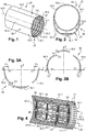
- a fuselage section 10 which has an approximately cylindrical shape and an axis A10 (parallel to the longitudinal direction).
- the fuselage section 10 extends between first and second transverse peripheral edges 10a, 10b arranged in transverse planes.
- the fuselage section 10 comprises a structure 12 which comprises longitudinal reinforcements 14.1 (called stringers) and transverse reinforcements 14.2 (called frames) and a skin 16 attached to the structure 12.
- the fuselage section 10 has an approximately circular cross-section S1 or, according to a second embodiment, an approximately ovoid cross-section S2.
- the fuselage section 10 comprises six panels 18.1 to 18.6 distributed over its circumference, a lower panel 18.1, lower right and left side panels 18.2, 18.3, upper right and left side panels 18.4, 18.5 and an upper panel 18.6.
- each panel 18.1 to 18.6 comprises a wall 20 forming part of the skin 16 of the section of the fuselage and a structure 12, attached to one of the faces called the internal face 22 of the wall 20, comprising longitudinal stiffeners 14.1 and portions transverse stiffeners 14.2.
- Each panel 18.1 to 18.6 comprises two parallel longitudinal edges 24.1, 24.2 and two transverse edges 26.1, 26.2 which constitute portions of the transverse peripheral edges 10a, 10b.
- Each panel 18.1 to 18.6 is produced at the level of a first production unit which may be distant from a second production unit at the level of which the panels 18.1 to 18.6 are assembled so as to obtain fuselage sections 10.
- each panel 18.1 to 18.6 comprises a framework 28, integral with the internal face 22, connected to the panel by at least one removable connection, for example using pins or screws screwed into the threads provided at the level of the structure 12 of panel 18.1 to 18.6.
- this framework 28 comprises a frame 28.1 as well as longitudinal 28.2, transverse 28.3 and oblique 28.4 reinforcements.
- This frame 28 is configured to limit the deformations of the panel 18.1 to 18.6, in particular during transport. Other functions of the frame 28 will be specified later.
- the panels 18.1 to 18.6 are stored in containers 30 to ensure in particular the transport of the panels 18.1 to 18.6 from one production unit to another.
- each container 30 contains two panels 18.2 to 18.3 suspended on a storage support 31.
- the frame 28 comprises at least three panel interfaces 32 for suspending each panel 18.1 to 18.6 on a storage support. These panel interfaces 32 will be detailed later.
- the invention is not limited to this embodiment for the storage of the panels 18.1 to 18.6.
- the fuselage section 10 is obtained by assembling a lower part of the section 34, obtained by previously assembling at least two panels, and an upper part 36 obtained by previously assembling at least two panels.
- the lower part 34 (visible on the Figure 3A ) comprises a lower panel 18.1 and lower right and left side panels 18.2, 18.3, the upper part of the section 36 (visible on the Figure 3B ) comprising a top panel 18.6 and upper right and left side panels 18.4, 18.5.
- the assembly method may include a step of controlling the positioning of the panels 18.1 to 18.6 prior to the step of joining the panels so as to obtain a lower or upper part of the section 34, 36.
- each step of joining the panels 18.1 to 18.6 comprises a step of joining the walls 20 of the panels 18.1 to 18.6 and a step of joining the structures 12 of the panels 18.1 to 18.6 and more particularly the portions of the transverse stiffeners 14.2 of the panels 18.1 to 18.6 between them.
- the step of joining the lower and upper parts of the section 34, 36 comprises a step of joining the walls 20 of the lower and upper parts of the section 34, 36 as well as a step of joining the structures 12 and more particularly the portions of the stiffeners transverse 14.2 of the lower and upper parts of the section 34, 36.
- the production unit 38 comprises, for the lower part of the section 34, a first positioning control station 50, inserted between the first positioning station 40 and the first junction station 42 and/or, for the upper part of section 36, a second positioning control station 52 inserted between the second positioning station 44 and the second junction station 46.
- the first junction station 42 can be broken down into a first junction station 42.1 of the walls 20 of the panels 18.1 to 18.3 and a first junction station 42.2 of the structures 12 of the panels 18.1 to 18.3.
- the second junction station 46 can be broken down into a second junction station 46.1 of the walls 20 of the panels 18.4 to 18.6 and a second junction station 46.2 of the structures 12 of the panels 18.4 to 18.6.
- the positioning and junction station 48 of the lower and upper parts of the section 34, 36 could be broken down into several stations, for example one dedicated to positioning, another dedicated to the junction of the walls and finally another dedicated to the junction of structures.
- the production unit 38 comprises at least one lower mounting bracket 54 configured to support the lower panel 18.1 and the lower right and left side panels 18.2, 18.3 then move them from one station to another, as well as at least one top mounting bracket 56 configured to support top panel 18.6 and top right and left side panels 18.4, 18.5 and move them from station to station.
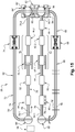
- the production unit 38 comprises at least two paths, a first path 58 configured to allow the lower mounting support 54 to move from the first positioning station 40 of the panels 18.1 to 18.3 to the first position of junction 42 of the panels 18.1 to 18.3 as well as a second path 60 configured to allow the upper mounting bracket 56 to move from the second positioning station 44 of the panels 18.4 to 18.6 to the second junction station 46 of the panels 18.4 to 18.6 , the positioning and joining station 48 of the lower parts and upper section 34, 36 being positioned at the level of the first path 58 or the second path 60.
- the first path 58 describes a closed loop to allow all the lower mounting brackets 54 to return, after the assembly of a fuselage section 10, to the first positioning station 40 of the panels 18.1 to 18.3.
- the second path 60 describes a closed loop to allow all the upper mounting brackets 56 to return, after the assembly of a fuselage section 10, to the second positioning station 44 of the panels 18.1 to 18.3.
- the production unit 38 comprises a transfer station 62 allowing the lower 54 or upper 56 mounting brackets to pass from one path to the other so as to reach the positioning and joining station 48 of the first and second parts of the section 34, 36.
- the first or second path 58, 60 comprising the positioning and junction station 48 has a mobile section configured to occupy a continuous position in which it ensures the continuity of the path so as to obtain a closed loop and a position shifted in which it opens the loop to allow the evacuation of the fuselage section 10 produced.
- the transfer station 62 allows each of the upper mounting brackets 56 to be transferred, after the second junction station 46, to the positioning and junction station 48 positioned at the level of the first path 58 after the first junction station 42.
- the first path 58 comprises a first mounting portion 64, which extends from a first upstream end 64.1 to a first downstream end 64.2, at which the first positioning station 40 is positioned. , the possible first positioning control station 50, the junction station(s) 42 and the positioning and junction station 48; as well as a first return portion 66, comprising at least a first reconditioning station 68, connecting the first downstream and upstream ends 64.1, 64.2 of the first assembly portion 64.
- the second path 60 comprises a second assembly portion 70, which extends from a second upstream end 70.1 to a second downstream end 70.2, at which the second positioning 44, the possible second positioning control station 52 and the junction station(s) 46; as well as a second return portion 72, comprising at least a second reconditioning station 74, connecting the second downstream and upstream ends 70.1, 70.2 of the second mounting portion 70.
- the transfer station 62 is configured to ensure the transfer of each upper mounting bracket 56 between the first and second downstream ends 64.2 and 70.2.
- the first and second conditioning stations 68, 74 are provided for removing the frames 28 and/or configuring the lower and upper mounting brackets 54, 56 depending on the fuselage to be produced.
- First path 58 is configured to allow each lower mounting bracket 54 to travel below first path 58, along the latter, stopping at each station; and each upper mounting bracket 56 to move above the first path 58, at least over a part of the latter, in particular that which extends between the first downstream end 64.2 and the positioning and junction station 48.
- the second path 60 is configured to allow each upper mounting bracket 56 to travel above the second path 60, along the latter, stopping at each position.
- the first path 58 is positioned at a height H1 greater than the height H2 of the second path 60.
- the height H1 of the first path 58 is determined so that the panels 18.1 to 18.3 of the fuselage sections having the largest cross sections can be secured to a lower mounting support 54 circulating under the first path 58 .
- each path 58, 60 comprises at least one rail 78, preferably two rails 78, 78' parallel to each other.
- the two rails 78, 78' are configured in the same way, same section and same spacing.
- the rails 78, 78' of the first path 58 are held in height by means of gantries 80 to allow the passage of the lower mounting brackets 54 under the first path 58 and the rails 78, 78' of the second path 60 are held in height by uprights 82 to allow the passage of the upper mounting brackets 54 on the second path 60.
- Each lower mounting bracket 54 includes at least one first guide system 84 enabling it to move along the rail(s) 78, 78', preferably at least two, one for each rail 78, 78'.
- at least one of the first guide systems 84 is motorized to allow each lower mounting bracket 54 to move along the rails 78, 78' independently.
- Each upper mounting bracket 56 includes at least one second guide system 86 enabling it to move along the rail(s) 78, 78', preferably at least two, one for each rail 78, 78'. According to one configuration, at least one of these second guide systems 86 is motorized to allow each upper mounting bracket 56 to move along the rails 78, 78' independently.
- each rail 78, 78' has an I-section and has a vertical web and upper and lower horizontal flanges provided at the ends of the vertical web.
- each first guide system 84 comprises two first sets of rollers 84.1 having vertical pivot axes, said first sets being arranged on either side of the vertical web of a rail 78, 78' and configured to roll on each side of the vertical web of a rail 78, 78'.
- Each first guide system 84 also comprises two second sets of rollers 84.2 having horizontal pivot axes, said second sets being arranged on either side of the vertical web of a rail 78, 78' and configured to roll on the bottom flange of a rail 78, 78'.
- each second guide system 86 comprises a first roller 86.1 which has a horizontal pivot axis and which is configured to roll on a bottom flange of a rail 78, 78'; as well as two second rollers 86.2, arranged on either side of the first roller 86.1, which have vertical pivot axes and which are configured to roll against the vertical web of a rail 78, 78'.
- the first and second return portions 66, 72 of the first and second paths 58, 60 each describe a U.
- the return portion 66, 72 and the assembly 64, 70 form an angle of 90°.
- Each of the first and second paths 58, 60 includes, at its upstream end 64.1, 70.1, a first or second upstream swing bridge 88, 88' configured to allow each lower or upper mounting bracket 54, 56 to pass, for each path 58, 60, from the return portion 66, 72 to the mounting portion 64, 70.
- Each of the first and second paths 58, 60 comprises, at its downstream end 64.2, 70.2, a first or second downstream swing bridge 90, 90' configured to allow each lower or upper mounting bracket 54, 56 to pass, for each path 58, 60, from the mounting portion 64, 70 to the return portion 66, 72.
- each turntable 88, 88', 90, 90' comprises a disc-shaped platform, movable about a vertical pivot axis, which has two rails configured to be aligned alternately either with the rails 78, 78' of the return portion 66, 72 or with the rails 78, 78' of the mounting portion 64, 70.
- the transfer station 62 further comprises first and second downstream swing bridges 90, 90' provided at the level of the first and second downstream ends 64.2, 70.2 of the first and second paths 58, 60, a transfer path 92 connecting the first and second downstream swing bridges 90, 90' and at least one elevator 94 for at least one of the first and second downstream swing bridges 90, 90' to compensate for the difference in height between the first and second paths 58, 60 and to allow the evacuation of the fuselage section 10 produced.
- the transfer path 92 is at the same height as the first path 58 and the transfer station 62 comprises a first lift 94 for the first downstream traveling crane 90 of the first path 58 in order to allow the evacuation of the section of completed fuselage; as well as a second elevator 94' for the second downstream traveling crane 90' of the second path 60 to compensate for the difference in height between the first and second paths 58, 60.
- the invention is not limited to these embodiments for the paths 58, 60, for the guidance systems 84, 86, for the transfer station 62.
- at least one upper or lower mounting brackets 54, 56 is moved so that upper mounting bracket 56 is positioned above lower mounting bracket 54 at positioning and joining station 48.
- the production unit 38 also includes a storage area 96 at which the panels 18.1 to 18.6 are stored before being assembled. According to one configuration, the storage area 96 is positioned in the extension of the first and second assembly portions 64, 70, close to the upstream swing bridges 88, 88'.
- the production unit 38 includes transport carriages 98 for transporting each of the panels 18.1 to 18.6 from the storage area 96 to one of the first and second positioning stations 40, 44.
- each transport trolley 98 comprises a rolling base 100 and at least two vertically telescopic uprights 102 to which is connected a panel 18.2 to 18.5, configured to allow said panel 18.2 to 18.5 to be moved vertically in order to fix it to a lower mounting support or top 54, 56.
- Some transport carts 98 are configured to transport right side panels and others for left side panels.
- Each transport cart 98' for the upper and lower panels 18.1, 18.6 includes a rolling base 104 configured to receive a panel 18.1, 18.6.
- the lower mounting bracket 54 comprises a frame 108, movable in a direction of movement DD, having interfaces 110.1 to 110.6 configured to cooperate with panel interfaces 32 in order to secure the panels 18.1 to 18.3 in a given position to the mounting bracket lower 54.
- the frame 108 is telescopic and comprises a front frame 108.1, a rear frame 108.2 as well as a telescopic link 112, connecting the front and rear frames 108.1 and 108.2, configured to occupy a mobile state in which the telescopic link 112 makes it possible to separate the front and rear frames 108.1, 108.2 more or less in the direction of movement DD in order to adjust their spacing and a locked state in which the telescopic link 112 holds the front and rear frames rear 108.1 and 108.2 in a given position.
- the telescopic link 112 comprises at least two telescopic tubes 112.1, 112.2.
- the lower mounting bracket 54 comprises at least one vertical movement system 114 configured to move the chassis 108 vertically, in particular a front vertical movement system 114.1 for the front chassis 108.1, and a rear vertical movement system 114.2 for the rear frame 108.2.
- each vertical displacement system 114, 114.1, 114.2 comprises a body 116, in the shape of an inverted U, to which are connected two guide systems 84 of the lower mounting support 54 with respect to the first path 58; as well as at least one vertical slide 118, preferably two slides 118 integral with the branches of the U, configured to connect the body 116 to the frame 108, in particular to the front or rear frame 108.1, 108.2.
- This configuration makes it possible in particular to be able to secure the lower panel 18.1 to the lower mounting support 54, as illustrated in the figures 11A to 11D .
- the presence of at least one vertical movement system 114 also makes it possible to be able to adjust the relative position of the lower and upper mounting brackets 54, 56 at the level of the positioning and junction station 48 according to the cross section of the fuselage section. 10 to be made, which improves the versatility of the lower and upper mounting brackets 54, 56.
- the upper mounting support 56 comprises a frame 120, movable in a direction of movement DD, having support interfaces 122.1 to 122.6 configured to cooperate with panel interfaces 32 in order to secure the panels 18.4 to 18.6 in a given position to the support of top mount 56.
- frame 120 could be telescoping and include a front frame and a rear frame connected by a telescoping link, adjustable according to the direction of movement DD, configured to alternately occupy mobile and blocked states.
- one of the lower and upper mounting brackets 54, 56 is not telescopic, it can support panels 18.1 to 18.6 of different lengths by adjusting the position of the panel interfaces 32 and/or the support interfaces 110.1 to 110.6, 122.1 at 122.6.
- At least one of the lower and upper mounting brackets 54, 56 comprises a vertical displacement system 114 of its frame 108, 120 to be able to adjust the relative position of the lower and upper mounting brackets 54 , 56 at the position of positioning and junction 48 depending on the cross section of the fuselage section 10 to achieve.
- each lower or upper mounting support 54, 56 comprises, for at least certain support interfaces 110.1 to 110.6, 122.1 to 122.6, an adjustable link 124 in three orthogonal directions Tx, Ty, Tz, connecting said interfaces 110.1 to 110.6, 122.1 to 122.6 to the frames 108, 120.
- all the support interfaces 110.1 to 110.6, 122.1 to 122.6 are each connected to the frames 108, 120 by an adjustable link 124 in three orthogonal directions Tx, Ty, Tz. This configuration makes it possible to adjust the position of each panel 18.1 to 18.6.
- each adjustable link 124 in three orthogonal directions Tx, Ty, Tz comprises a first slide 126.1, movable in a vertical direction Tz, connecting the frame 108, 120 to a first support 128.1, a second slide 126.2, movable in a horizontal direction Ty and perpendicular to the direction of movement DD, connecting the first support 128.1 to a second support 128.2 as well as a third slide 126.3, movable in a horizontal direction Tx and parallel to the direction of movement DD, connecting the second support 128.2 to a third support 128.3.
- the movements of the first, second and third supports 128.1 to 128.3 can be motorized and controlled by an automaton.
- each lower or upper mounting bracket 54, 56 can be adapted to different shapes and sizes of panels 18.1 to 18.6 depending on the cross section of the fuselage section 10 to be produced, which improves the versatility of the brackets upper and lower mounting brackets 54, 56.
- each lower or upper mounting bracket 54, 56 comprises at least three support interfaces 110.1 to 110.6, 122.1 to 122.6. According to one configuration, each lower or upper mounting bracket 54, 56 comprises three support interfaces 110.1 to 110.6, 122.1 to 122.6 for each panel 18.1 to 18.6 so as to obtain an isostatic connection between each panel 18.1 to 18.6 and each lower mounting bracket or higher 54, 56.
- the lower or upper mounting bracket 54, 56 comprises a front frame 108.1 and a rear frame 108.2
- the lower or upper mounting bracket 54, 56 comprises, for each panel 18.1 to 18.6, at least one support interface 110.1 to 110.6, 122.1 to 122.6 secured to the front frame 108.1 and at least one support interface 110.1 to 110.6, 122.1 to 122.6 secured to the rear frame 108.2.
- each support interface 110.1 to 110.6, 122.1 to 122.6 is configured to cooperate with a panel interface 32 in a centered position so that the panel interface 32 is immobilized in a known position with respect to the interface supports 110.1 to 110.6, 122.1 to 122.6.
- each support interface 110.1 to 110.6, 122.1 to 122.6 comprises a male part M configured to be introduced into a female part F secured to a panel interface 32.
- each support interface 110.1 to 110.6, 122.1 to 122.6 comprises a female part F configured to receive a male part M secured to a panel interface 32.
- each pair of support and panel interface comprises a male part M configured to be introduced according to an insertion direction SI in a female part F.
- the male part M When the male part M is in the centered position, the male part M is immobilized with respect to the female part F in a plane perpendicular to the direction of insertion SI. In the centered position, the male part M is in contact with an abutment of the female part F and can no longer translate according to the direction of introduction SI, it can only translate according to a direction opposite to the direction of introduction SI .
- the support interface 110.1 to 110.6, 122.1 to 122.6 and/or the panel interface 32 comprises a system for immobilizing in the centered position.
- a system of immobilization is necessary when the direction of introduction SI is vertical and oriented upwards or when the direction of introduction SI is horizontal. It is not necessary when the direction of introduction SI is vertical and oriented downwards.
- the immobilization system is a toggle clamp.
- the three support interfaces 110.1 to 110.3 intended for the lower panel 18.1 have a direction of introduction SI that is vertical and oriented upwards.
- the lower support interfaces 110.6, 122.6, intended for the upper and lower, right and left side panels 18.2 to 18.5, have a horizontal direction of introduction SI oriented towards the chassis 108, 120.
- the three support interfaces 122.1 to 122.3, intended for the panel upper 18.6, have a direction of introduction SI vertical and downwards.
- each panel 18.1 to 18.6 and its lower or upper mounting support 54, 56.
- This connection must be configured to allow the positioning (position and orientation) of each panel 18.1 to 18.6 to be adjusted according to a desired configuration and to immobilize each panel 18.1 to 18.6 relative to the lower and upper mounting brackets 54, 56 depending on the desired configuration.
- each lower or upper mounting support 54, 56 is equipped with force sensors making it possible to determine at least one force exerted by each panel 18.1 to 18.6 on the lower or upper mounting support 54, 56.
- each lower or upper mounting support 54, 56 comprises several force sensors making it possible to determine at several points the forces exerted by the panel 18.1 to 18.6 on the lower or upper mounting support 54, 56.
- These force sensors can be used to adjust the position of each panel 18.1 to 18.6 on each of the lower or upper mounting brackets 54, 56.
- each first or second positioning control station 50, 52 comprises at least one rangefinder 130 and each panel comprises several targets 132, each rangefinder 130 and each target 132 being configured to measure the distance separating the target 132 and the rangefinder 130.
- the number and the positioning of the rangefinders 130 are determined so as to allow the rangefinders 130 to determine the position of each panel 18.1 to 18.6 in a given frame of reference R.
- each lower and upper mounting bracket 52, 54 being known in the given frame of reference R and the position of each panel 18.1 to 18.6 also being known in the given frame of reference R, it is possible to determine the position of each panel 18.1 to 18.6 with respect to to each lower or upper mounting bracket 54, 56 and to adjust it using the adjustable links 124 according to a desired position.
- the first junction station 42.1 of the walls 20 comprises at least two welding heads 134, 134' movable in the direction of movement DD, a first welding head 134 ensuring the junction of the walls 20 of the lower panel 18.1 and of the lower side panel right 18.2 as well as a second welding head 134' ensuring the junction of the walls 20 of the lower panel 18.1 and of the lower left side panel 18.3.
- the second junction station 46.1 comprises at least two welding heads 136, 136 'movable according to the direction of movement DD, a first welding head 136 ensuring the junction of the walls 20 of the upper panel 18.6 and of the upper right side panel 18.4 as well as a second welding head 136' ensuring the junction of the walls 20 of the upper panel 18.6 and of the upper left side panel 18.5.
- the positioning and junction station 48 comprises at least two welding heads 138, 138', movable in the direction of movement DD, a first welding head 138 ensuring the junction of the walls 20 of the upper and lower straight side panels 18.2, 18.4 as well as a second welding head 138' ensuring the junction of the walls 20 of the upper and lower left side panels 18.3, 18.5.
- the invention is not limited to these embodiments for the first and second joining stations 42.1, 46.1 of the walls 20 and the positioning and joining station 48.
- the welding heads 134, 134' , 136, 136', 138, 138' could be replaced by effectors configured for setting rivets.
- the first and second joining stations 42.2, 46.2 of the structures 12 and the positioning and joining station 48 each comprise at least two automated equipment items 140, 140' configured to ensure the joining of the structures 12 to one another.
- the step of joining the structures 12 could be semi-automated or manual and carried out, at least in part, by at least one operator.
- the six panels 18.1 to 18.2 each equipped with a frame 28 are stored two by two in three containers 30 positioned in the storage area 96.
- Each of the panels 18.1 to 18.6 and/or each of the frames 28 comprise an identifier and optionally at least a marking mentioning at least one piece of data relating to the panel and/or the fuselage section to be produced.
- the production unit 38 comprises at least one identifier reader connected to a control station configured to control the various elements of the production unit. For each panel 18.1 to 18.6, the reading of the identifier by the identifier reader makes it possible, automatically and autonomously, to determine the transport trolley 98, 98' to be used to transport the panel 18.1 to 18.6, the first or second positioning station 40, 44 to which the panel 18.1 must be routed at 18.6, the lower or upper mounting bracket 54, 56 for which the panel 18.1 to 18.2 is intended, the length adjustment of the lower and upper mounting brackets 52, 54, the positioning of the panel 18.1 to 18.6 on the lower mounting bracket or higher 54, 56...
- each panel 18.1 to 18.6 from the container 30 to a transport trolley 98, 98' can be automated.
- the movements of each transport carriage 98, 98' from the storage area 96 to the first or second positioning station 40, 44 can also be automated and controlled by an automaton.
- each transport carriage 98, 98' is positioned relative to the lower mounting bracket 54. As illustrated in the figure 11A , the transport carriages 98, 98' are positioned so that the lower panel 18.1 is positioned below and plumb with the lower mounting bracket 54 and the lower right and left side panels 18.2, 18.3 on either side of the lower panel 18.1.
- the support interfaces 110.4 to 110.6 are positioned in a retracted position corresponding to their position during the demolding of the fuselage section 10 at the end of the assembly process.
- the frame 108 of the lower mounting bracket 54 is translated downwards until the support interfaces 110.1 to 110.3 are in contact with the panel interfaces 32 of the lower panel 18.1.
- the lower panel 18.1 is then secured to the lower mounting bracket 54.
- the lower right and left side panels 18.2, 18.3 are translated upwards using the telescopic uprights 102 of the transport carriages 98 so that the panel interfaces 32 of said lower right and left side panels 18.2, 18.3 are substantially at the same height as support interfaces 110.4 to 110.6 corresponding.
- the lower right and left side panels 18.2, 18.3 are then secured to the lower mounting bracket 54.
- the frame 108 is translated upwards into a nominal position corresponding to the position of the frame during the assembly of the section of the fuselage 10.
- each transport carriage 98, 98' is positioned relative to the upper mounting support 56.
- the upper panel 18.6 is positioned on the upper mounting support 56 by any appropriate means, by causing the upper support interfaces 122.1 to 122.3 with the panel interfaces 32, then the upper panel 18.6 is secured to said upper mounting support 56.
- the upper right and left side panels 18.4, 18.5, positioned on transport carriages 98 arranged on either side of the upper mounting bracket 56, are translated upwards using the telescopic uprights 102 of the transport carriages 98 so as to so that the panel interfaces 32 of said upper right and left side panels 18.4, 18.5 are substantially at the same height as the corresponding support interfaces 122.4 to 122.6.
- the upper right and left side panels 18.4, 18.5 are then secured to the upper mounting bracket 56.
- panels 18.1 through 18.6 can be pre-positioned using adjustable links 124.
- the two lower and upper mounting supports 54, 56 are moved as far as the first and second positioning control stations 50, 52. Thanks to the values measured by the rangefinders 130 and/or to the values of the forces measured by the force sensors fitted to the lower and upper mounting brackets 54, 56, the position of each panel 18.1 to 18.6 is corrected thanks to the adjustable links 124. This positioning correction operation can be automated.
- the values measured by the rangefinders 130 and/or the force values measured by the force sensors are transmitted to a computer configured to determine correction values for each of the translational movements in the directions Tx, Ty, Tz of each adjustable link 124 and to transmit these correction values to the adjustable links 124 concerned, the adjustable links 124 being configured to carry out autonomously and automatically translation movements according to the directions Tx, Ty, Tz according to the determined correction values by the computer.
- the panels 18.1 to 18.6 are correctly positioned with respect to the lower and upper mounting brackets 54, 56, the latter are moved to the first and second junction stations 42.1, 46.1 of the walls 20.
- the junction of the walls 20 of the lower panel 18.1 and of the lower right side panel 18.2 as well as the junction of the walls 20 of the lower panel 18.1 and of the lower left side panel 18.3 are made by welding or riveting.
- the junction of the walls 20 of the upper panel 18.6 and of the upper right side panel 18.4 as well as the junction of the walls 20 of the upper panel 18.6 and of the upper left side panel 18.5 are made by welding or riveting.
- the lower and upper mounting brackets 54, 56 are moved to the first and second junction stations 42.2, 46.2 of the structures 12.
- the junction of the structures 12 of the lower panel 18.1 and of the lower right side panel 18.2 as well as the junction of the structures 12 of the lower panel 18.1 and of the lower left side panel 18.3 are made by welding or riveting.
- the junction of the structures 12 of the upper panel 18.6 and of the upper right side panel 18.4 as well as the junction of the structures 12 of the upper panel 18.6 and the upper left side panel 18.5 are made by welding or riveting.
- the lower and upper mounting brackets 54, 56 are moved to the positioning and joining station 48.
- the upper mounting bracket 56 is moved to the second downstream swing bridge 90' of the second path 60, as illustrated in the Fig. 18A .
- the second downstream swing bridge 90' is translated upwards thanks to the second elevator 94' so as to be positioned approximately at the same height as the first path 58, as illustrated in the figure 18B .
- the second downstream swing bridge 90' is pivoted 90° so that the upper mounting bracket 56 can move from the second downstream swing bridge 90' of the second path 60 to the first downstream swing bridge 90 of the first path 58 by taking the transfer path 92, as shown in the Fig. 18C .
- the first downstream swing bridge 90 is pivoted so that the upper mounting bracket 56 can move on the first path 58 to reach the positioning and joining station 48, as illustrated in the figure 18D .
- the upper mounting bracket 56 When the upper mounting bracket 56 has reached the positioning and joining station 48, it is positioned above the lower mounting bracket 54, as shown in the figure below. Figure 18E .
- the upper part of the section 36 composed of the upper panel 18.6 and the upper right and left side panels 18.4, 18.5, is then positioned relative to the lower part of the section 34 composed of the lower panel 18.1 and the lower right and left side panels 18.2 , 18.3 by acting in a coordinated manner on the adjustable links 124 of the upper assembly support 56 and/or on the displacement system 114, as illustrated in the Figure 18E .
- the junction between the upper and lower right side panels 18.2, 18.4 and the junction between the upper and lower left side panels 18.3, 18.5 are made both at the level of the walls 20 than of the structures 12, as illustrated in the figure 19 .
- each carriage 142 comprises a rolling base 142.1 and a series of balanced cradles 142.2 configured to receive the fuselage section 10 and to move vertically with respect to the rolling base 142.1, as illustrated in the figure 20G .
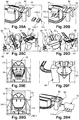
- the carriages 142 are positioned under the fuselage section 10 and their cradles 142.2 are moved upwards so as to come into contact with the fuselage section 10, as illustrated on the figure 20B .
- the upper mounting bracket 56 is detached from the panels 18.4 to 18.6 of the fuselage section 10 then it is transferred to the first downstream swing bridge 90, then towards the transfer path 92 after pivoting of the first downstream swing bridge 90, then to the second lift 94' and finally towards the second return portion 72 of the second path 60 after the descent of the second lift 94', as illustrated in the figures 20C and 20D .
- the frames 28 are detached from the panels 18.4 to 18.6, then the upper mounting bracket 56 supporting the frames 28 is transferred to the second return portion 72 of the second path 60, as previously described.
- At least one reinforcement 144 can be put in place to stiffen the upper part of the section 36, as illustrated in the figure 20E .
- the lower mounting bracket 54 is detached from the panels 18.1 to 18.3 of the fuselage section 10 then it is transferred to the first downstream swing bridge 90, then to the first return portion 66 of the first path 58 after pivoting of the first downstream swing bridge 90 , as shown in the figure 20F .
- the frames 28 connected to the lower mounting bracket 54 are detached from the panels 18.1 to 18.3 and the lower mounting bracket 54 to which the frames 28 are connected is transferred to the first return portion 66 of the first path 58, as previously described. .
- the first downstream swing bridge 90 After having moved the cradles 142.2 of the carriages 142 downwards, as illustrated in the figure 20G , the first downstream swing bridge 90 is moved upwards thanks to the first elevator 94 to allow the carriages 142 supporting the fuselage section 10 to pass under the first downstream swing bridge 90 and to evacuate the fuselage section 10, as illustrated in the figure 20H .
- the first downstream swing bridge 90 performs the function of the mobile section, configured to occupy a continuous position or an offset position in which it opens the loop formed by the first path 58 to allow the fuselage section produced to be evacuated.
- the fact of producing the fuselage section 10 by assembling the lower and upper parts of the section 34, 36, each of them being obtained by assembling at least two panels, allows whatever the section of the fuselage section (and therefore the family aircraft) to be able to use the same assembly process and the same production unit.
- the same production unit can be used to assemble fuselage sections from different families of aircraft.
- the upper and lower mounting brackets 56, 54 are versatile and can be used to assemble the fuselage section panels 10 whatever the section of said fuselage section. Thanks to their adjustable links 124, the upper and lower mounting brackets 54, 56 make it possible to quickly position the panels between them.
- the assembly method according to the invention makes it possible to easily automate the various stages of assembly of a fuselage section, which results in a gain in productivity.
Landscapes
- Engineering & Computer Science (AREA)
- Transportation (AREA)
- Manufacturing & Machinery (AREA)
- Aviation & Aerospace Engineering (AREA)
- Mechanical Engineering (AREA)
- Physics & Mathematics (AREA)
- Optics & Photonics (AREA)
- Automatic Assembly (AREA)
Claims (17)
- Verfahren zum Zusammensetzen eines Rumpfabschnitts (10) aus mehreren Paneelen (18.1 bis 18.6), wobei das Verfahren umfasst: Schritte des Positionierens und Verbindens von wenigstens zwei Paneelen (18.1 bis 18.3), um einen unteren Teil des Abschnitts (34) zu erhalten, wobei die Paneeln (18.1 bis 18.3) des unteren Teils des Abschnitts (34) an einer unteren Montagehalterung (54) befestigt sind, die dazu eingerichtet ist, sich entlang einer ersten Bahn (58) zu bewegen; Schritte des Positionierens und Verbindens von wenigstens zwei Paneelen (18.4 bis 18.6), um einen oberen Teil des Abschnitts (36) zu erhalten, wobei die Paneele (18.4 bis 18.6) des oberen Teils des Abschnitts (36) an einer oberen Montagehalterung (56) befestigt sind, die dazu eingerichtet ist, sich entlang einer zweiten Bahn (60) zu bewegen; einen Schritt des Bewegens wenigstens einer der unteren oder oberen Montagehalterungen (54, 56), so dass die obere Montagehalterung (56) über der unteren Montagehalterung (54) positioniert ist; Schritte des Positionierens und Verbindens der unteren und oberen Teile des Abschnitts (34, 36), um den Rumpfabschnitt (10) zu erhalten, sowie Schritte des Entformens und Abtransports des hergestellten Rumpfabschnitts (10).
- Verfahren zum Zusammenbauen eines Rumpfabschnitts (10) nach Anspruch 1, bei dem das Verfahren für jede untere oder obere Montagehalterung (54, 56) einen Schritt des Steuerns der Positionierung jedes Paneels (18.1 bis 18.6) aufweist und einen Schritt des Korrigierens der Positionierung jedes Paneels (18.1 bis 18.6) durch ein Verbindungsglied, das jedes Paneel (18.1 bis 18.6) und eine der unteren und oberen Montagehalterungen (54, 56) verbindet und dazu eingerichtet ist, das Einstellen der Positionierung jedes Paneels (18.1 bis 18.6) auf eine gewünschte Konfiguration zu ermöglichen und die Paneele (18.1 bis 18.6) relativ zu den unteren und oberen Montagehalterung (54, 56) gemäß der gewünschten Konfiguration zu fixieren.
- Verfahren zum Zusammenbauen eines Rumpfabschnitts (10) nach dem vorhergehenden Anspruch, bei dem jedes Paneel (18.1 bis 18.6) lösbar mit einem Gerüst (28) verbunden ist, das mit wenigstens drei Paneelnschnittstellen (32) ausgestattet ist, bei dem jede untere oder obere Montagehalterung (54, 56) wenigstens ein entlang des ersten oder zweiten Wegs (58, 60) bewegliches Gestell (108, 120) aufweist und für jedes Paneel (18.1 bis 18.6) wenigstens drei Trägerschnittstellen (110.1 bis 110.6, 122.1 bis 122.6) aufweist, die jeweils über eine in drei orthogonale Richtungen (Tx, Ty, Tz) verstellbare Anschlüsse (124) mit dem Gestell (108, 120) verbunden sind, und bei dem der Schritt des Positionierens jedes Paneels (18.1 bis 18.6) auf einer der unteren und oberen Montagehalterungen (54, 56) darin besteht, dass jede Paneelnschnittstelle (32) mit einer der Trägerschnittstellen (110.1 bis 110.6, 122.1 bis 122.6) in einer zentrierten Position zusammenwirkt, so dass die Position jeder Paneel (18.1 bis 18.6) In Bezug auf eine der unteren und oberen Befestigungshalterungen (54, 56) bekannt ist.
- Verfahren zum Zusammenbauen eines Rumpfabschnitts (10) nach einem der vorhergehenden Ansprüche, bei dem dieobere Montagehalterung (56) auf der ersten Bahn (58) übertragen wird, an der die Schritte des Positionierens und der Verbindung des unteren und oberen Teils des Abschnitts (34, 36) ausgeführt werden.
- Verfahren zum Zusammenbauen eines Rumpfabschnitts (10) nach einem der vorhergehenden Ansprüche, bei dem die erste und die zweite Bahn (58, 60) jeweils eine geschlossene Schleife beschreiben und bei dem die Schleife, die durch die erste oder zweite Bahn (58, 60) gebildet ist und bei der der Schritt des Positionierens und Verbindens der unteren und oberen Teile des Abschnitts (34, 36) ausgeführt wird, offen ist, um den Schritt des Abtransports des Rumpfabschnitts (10) zu ermöglichen.
- Werkzeug zur Durchführung des Verfahrens zum Zusammenbau eines Rumpfabschnitts nach einem der Ansprüche 1 bis 5, wobei das Werkzeug eine untere oder obere Montagehalterung (54, 56) aufweist, die ein Gestell (108, 110) aufweist und für jedes Paneel (18.1, 18.6) wenigstens drei Trägerschnittstellen (110.1 bis 110.6, 122.1 bis 122.6) hat, die jeweils über einen in drei orthogonale Richtungen (Tx, Ty, Tz) verstellbaren Anschluss (124) mit dem Gestell (108, 120) verbunden sind, sowie für jedes Paneel (18.1, bis 18.6) ein Gerüst (28) aufweist, das lösbar mit dem Paneel (18.1 bis 18.6) verbunden werden kann und das dessen Verformungen während des Transports begrenzt und das mit wenigstens drei Paneelschnittstellen (32) ausgestattet ist, die jeweils dazu eingerichtet sind, mit einer Trägerschnittstelle (110.1 bis 110.6, 122.1 bis 122.6) in einer zentrierten Position zusammenzuwirken.
- Werkzeug nach Anspruch 6, bei dem das Gestell (108, 120) teleskopierbar ist und einen vorderen Rahmen (108.1), einen hinteren Rahmen (108.2) und eine den vorderen und hinteren Rahmen (108.1, 108.2) verbindende Teleskopstange (112) aufweist, die dazu eingerichtet ist, einen beweglichen Zustand einzunehmen, in dem es die Teleskopverbindung (112) ermöglicht, den vorderen und den hinteren Rahmen (108.1, 108.2) mehr oder weniger voneinander zu entfernen, und einen blockierten Zustand einzunehmen, in dem die Teleskopverbindung (112) den vorderen und hinteren Rahmen (108.1, 108.2) in einer gegebenen Position hält.
- Werkzeug nach Anspruch 6 oder 7, bei dem die untere oder obere Montagehalterung (54, 56) wenigstens ein vertikales Bewegungssystem (114) aufweist, das dazu eingerichtet ist, das Gestell (108, 120) vertikal zu bewegen.
- Werkzeug nach dem vorhergehenden Anspruch, bei dem jedes vertikale Bewegungssystem (114) einen Körper (116) aufweist, an dem zwei Führungssysteme (84, 86) der unteren oder oberen Montagehalterung (54, 56) für die erste oder zweite Bahn (58, 60) angebracht sind, sowie wenigstens eine vertikale Gleitvorrichtung (118) aufweist, die dazu eingerichtet ist, den Körper (116) mit dem Gestell (108, 120) zu verbinden.
- Werkzeug nach einem der Ansprüche 6 bis 9, bei dem jede untere oder obere Montagehalterung (54, 56) Kraftsensoren zum Ermitteln wenigstens einer von jedem Paneel (18.1 bis 18.6) auf die untere oder obere Montagehalterung (54, 56) ausgeübten Kraft aufweist.
- Werkzeug nach einem der Ansprüche 6 bis 10, bei dem für zumindest bestimmte Paare von Träger- und Paneelnschnittstellen die Trägerschnittstelle (110.1 bis 110.6, 122.1 bis 122.6) und/oder die Paneelnschnittstelle (32) ein System zum Fixieren in zentrierter Position aufweist.
- Werkzeug nach einem der Ansprüche 6 bis 11, bei dem jedes Paar von Träger- und Paneelnschnittstellen ein männliches Teil (M) und ein weibliches Teil (F) mit einem Anschlag aufweist, wobei das männliche Teil dazu eingerichtet ist, in das weibliche (F) in Einführrichtung (SI) bis zum Anschlag in der zentrierten Position eingeführt zu werden, wobei das männliche Teil (M) und das weiblichen Teil (F) so eingerichtet sind, dass in der zentrierten Position das männliche Teil (M) gegenüber dem weiblichen Teil (F) in einer zur Einführrichtung (SI) rechtwinklingen Ebene fixiert ist und in die Einführrichtung (SI) nicht verschiebbar ist.
- Fertigungseinheit zur Ausführung des Verfahrens zum Zusammenbau eines Rumpfabschnitts nach einem der Ansprüche 1 bis 5, wobei die Fertigungseinheit eine erste Bahn (58) mit einer ersten Positionierstation (40) für die Paneele (18.1 bis 18.3) und mit einer ersten Verbindungsstation (42) für die Paneele (18.1 bis 18.3) sowie ein Werkzeug mit einer unteren Montagehalterung (54) nach einem der Ansprüche 6 bis 12 aufweist, die entlang des ersten Weges von der ersten Positionierstation (40) für die Paneele (18.1 bis 18.3) zur ersten Verbindungsstation (42) für die Paneele (18.1 bis 18.3) verfahrbar ist, und eine zweite Bahn (60) mit einer zweiten Positionierstation (44) für die Paneele (18.4 bis 18.6) und einer zweiten Verbindungsstation (46) für die Paneele (18.4 bis 18.6) sowie ein Werkzeug mit einer oberen Montagehalterung (56) nach einem der Ansprüche 6 bis 12 aufweist, die entlang des zweiten Weges von der zweiten Positionierstation (44) für die Paneele (18.4 bis 18.6) zur zweiten Verbindungsstation (46) für die Paneele (18.4 bis 18.6) verfahrbar ist, und eine Übergabestation (62) aufweist, die es den unteren (54) oder oberen (56) Montagehalterungen ermöglicht, sich von einer Bahn zur anderen zu bewegen, um eine Positionier- und Verbindungsstation (48) des ersten und zweiten Teils des Abschnitts (34, 36) zu erreichen.
- Produktionseinheit nach dem vorhergehenden Anspruch, bei der die Positionier- und Verbindungsstation (48) des unteren und oberen Teils des Abschnitts (34, 36) im Bereich der ersten Bahn (58) angeordnet ist und bei der die erste Bahn (58) so eingerichtet ist, dass sich jede untere Montagehalterung(54) unter der ersten Bahn (58) bewegen kann und sich jede obere Montagehalterung (56) über zumindest einem Teil der ersten Bahn (58) bewegen kann, und bei der die zweite Bahn (60) so eingerichtet ist, dass diese jeder oberen Montagehalterung (56) ermöglicht, sich über der zweiten Bahn (60) zu bewegen.
- Produktionseinheit nach Anspruch 13 oder 14, bei der der erste Weg (58) eine geschlossene Schleife beschreibt, um zu ermöglichen, dass alle unteren Montagehalterungen (54) nach der Montage eines Rumpfabschnitts (10) an die erste Positionierstation (40) der Paneele (18.1 bis 18.3) zurückkehren, und bei der der zweite Weg (60) eine geschlossene Schleife beschreibt, um zu ermöglichen, dass alle oberen Montagehalterungen (56) nach der Montage eines Abschnitts des Rumpfes (10) zur zweiten Positionierstation (44) der Paneele (18.1 bis 18.3) zurückkehren.
- Produktionseinheit nach einem der Ansprüche 13 bis 15, bei der die Übergabestation (62) erste und zweite nachgeordnete Drehbrücken (90, 90') aufweist, die im Bereich der ersten und zweiten Bahn (58, 60) vorgesehen sind, und eine Übergabebahn (92) zum Verbinden der ersten und zweiten nachgeordneten Drehbrücken (90, 90') und wenigstens einen Aufzug (94) für wenigstens eine der ersten und zweiten nachgeordneten Drehbrücken (90, 90') aufweist.
- Produktionseinheit nach Anspruch 16, bei der die Übergabebahn (92) auf der gleichen Höhe wie die erste Bahn (58) liegt und die Übergabestation (62) einen ersten Aufzug (94) für die erste nachgeordnete Drehbrücke (90) der ersten Bahn (58) sowie einen zweiten Aufzug (94') für die zweite nachgeordnete Drehbrücke (90') der zweiten Bahn (60) aufweist.
Applications Claiming Priority (1)
| Application Number | Priority Date | Filing Date | Title |
|---|---|---|---|
| FR1858741A FR3086268A1 (fr) | 2018-09-25 | 2018-09-25 | Procede d’assemblage d’un troncon de fuselage d’aeronef a partir de deux parties superieure et inferieure superposees, support de montage polyvalent, outillage et unite de production de troncons de fuselage pour la mise en œuvre dudit procede |
Publications (2)
| Publication Number | Publication Date |
|---|---|
| EP3628599A1 EP3628599A1 (de) | 2020-04-01 |
| EP3628599B1 true EP3628599B1 (de) | 2022-01-12 |
Family
ID=65243855
Family Applications (1)
| Application Number | Title | Priority Date | Filing Date |
|---|---|---|---|
| EP19197623.2A Active EP3628599B1 (de) | 2018-09-25 | 2019-09-16 | Verfahren, werkzeug und anlage zur herstellung von rumpfabschnitten eines luftfahrzeugs |
Country Status (4)
| Country | Link |
|---|---|
| US (1) | US11267585B2 (de) |
| EP (1) | EP3628599B1 (de) |
| CN (1) | CN110937131B (de) |
| FR (1) | FR3086268A1 (de) |
Families Citing this family (22)
| Publication number | Priority date | Publication date | Assignee | Title |
|---|---|---|---|---|
| EP3959140B1 (de) * | 2019-04-25 | 2026-01-07 | AeroVironment, Inc. | Bodenunterstützungsausrüstung für ein flugzeug für hohe flughöhen und lange flugdauern. |
| AU2020315515B2 (en) | 2019-04-25 | 2025-12-04 | Aerovironment, Inc. | Method of operating a high altitude long endurance aircraft for maximizing solar capture |
| US11518514B2 (en) | 2019-04-25 | 2022-12-06 | Aerovironment, Inc | Off-center parachute flight termination system including latch mechanism disconnectable by burn wire |
| AU2020307360B2 (en) | 2019-04-25 | 2025-09-25 | Aerovironment, Inc. | Method of flight plan optimization of a high altitude long endurance aircraft |
| SG11202111296TA (en) | 2019-04-25 | 2021-11-29 | Aerovironment Inc | Methods of climb and glide operations of a high altitude long endurance aircraft |
| US11383817B2 (en) * | 2019-07-19 | 2022-07-12 | The Boeing Company | Modular fuselage assemblies for aircraft, aircraft including modular fuselage assemblies, and MEl'hods of assembling modular fuselage assemblies |
| FR3100232B1 (fr) * | 2019-08-30 | 2022-01-14 | Airbus | Ensemble comportant une tour support et au moins deux systemes de support pour des panneaux d’un troncon de fuselage d’un aeronef |
| FR3106576B1 (fr) * | 2020-01-28 | 2022-02-11 | Airbus | Procédé d’assemblage sur chariot d’un tronçon central de fuselage d’aéronef |
| FR3114573B1 (fr) * | 2020-09-30 | 2022-11-18 | Airbus Operations Sas | Installation d’assemblage au sol de deux tronçons de fuselage au moyen d’un chariot de transport associé à un support ajustable |
| US11801576B2 (en) | 2020-11-18 | 2023-10-31 | The Boeing Company | Aircraft assembly formed of mating half barrel sections and the method of assembling the same |
| NL2027401B1 (en) * | 2021-01-26 | 2022-08-17 | Boeing Co | Aircraft assembly formed of mating half barrel sections and the method of assembling the same |
| US11724346B2 (en) * | 2020-11-18 | 2023-08-15 | The Boeing Company | Moving line assembly of airframes |
| NL2027402B1 (en) * | 2021-01-26 | 2022-08-19 | Boeing Co | Aircraft assembly formed of mating half barrel sections and the method of assembling the same |
| US11807396B2 (en) * | 2020-11-18 | 2023-11-07 | The Boeing Company | Mirrored fabrication and assembly of aircraft wings |
| EP4011783B1 (de) * | 2020-12-09 | 2023-08-30 | The Boeing Company | Fraktionierte impulsleitung für flugzeugrumpfherstellung |
| CN113909719B (zh) * | 2021-10-09 | 2022-09-30 | 中国直升机设计研究所 | 一种轻型无人机机身骨架焊接装置 |
| US11760036B2 (en) * | 2021-12-17 | 2023-09-19 | Rohr, Inc. | Systems and methods for induction welding |
| CN114633496B (zh) * | 2022-03-25 | 2023-11-21 | 中航复合材料有限责任公司 | 一种复合材料筒段结构整体成型工装的脱模装置及方法 |
| US11866201B2 (en) * | 2022-05-03 | 2024-01-09 | The Boeing Company | Method and apparatus for the application of frame to fuselage pull-up force via fuselage skin waterline tensioning |
| FR3138122A1 (fr) * | 2022-07-25 | 2024-01-26 | Airbus Operations | Système de transport de grille de plancher de cabine d’aéronef en vue d’un assemblage d’un corps de fuselage d’aéronef et procédé de calibration dudit système de transport. |
| CN115946865B (zh) * | 2023-02-28 | 2023-05-12 | 中航成飞民用飞机有限责任公司 | 用于大飞机下部组件正位集成的装配工装及其施工方法 |
| CN116372456B (zh) * | 2023-06-07 | 2023-07-28 | 福建威曼动力科技有限公司 | 一种柴油发电机组箱体加工用焊接设备 |
Family Cites Families (22)
| Publication number | Priority date | Publication date | Assignee | Title |
|---|---|---|---|---|
| US5427300A (en) * | 1994-03-22 | 1995-06-27 | Progressive Tool & Industries Co. | Apparatus for framing vehicle bodies |
| ES2146140B1 (es) * | 1996-10-15 | 2001-04-01 | Torres Martinez M | Maquina para el soporte y mecanizado de piezas. |
| US5848458A (en) * | 1997-05-15 | 1998-12-15 | Northrop Grumman Corporation | Reconfigurable gantry tool |
| ES2169620B1 (es) * | 1999-01-22 | 2003-11-01 | Torres Ingenieria De Procesos | Util para el montaje de secciones del fuselaje de aeronaves. |
| DE19929471C1 (de) * | 1999-06-26 | 2001-01-18 | Eads Airbus Gmbh | Verfahren und Vorrichtung zur Herstellung eines dreidimensionalen Großbauteiles |
| US7503368B2 (en) * | 2004-11-24 | 2009-03-17 | The Boeing Company | Composite sections for aircraft fuselages and other structures, and methods and systems for manufacturing such sections |
| DE102005054869A1 (de) * | 2005-11-17 | 2007-05-31 | Airbus Deutschland Gmbh | Verfahren zur Herstellung einer Rumpfzelle eines Luftfahrzeugs |
| ES2294947B1 (es) * | 2006-09-27 | 2009-02-16 | Airbus España, S.L. | Plataforma movil de transporte para la manipulacion de piezas aeronauticas. |
| US7735779B2 (en) * | 2006-11-02 | 2010-06-15 | The Boeing Company | Optimized fuselage structure |
| US7967250B2 (en) * | 2008-05-12 | 2011-06-28 | EMBRAER—Empresa Brasileira de Aeronáutica | Hybrid aircraft fuselage structural components and methods of making same |
| US8088450B2 (en) * | 2009-03-13 | 2012-01-03 | The Boeing Company | Automated wing painting system |
| CN201423426Y (zh) * | 2009-04-24 | 2010-03-17 | 东风设计研究院有限公司 | 车架铆接总拼夹具 |
| FR2976916B1 (fr) * | 2011-06-27 | 2013-07-26 | Airbus Operations Sas | Dispositif et procede d'assemblage de deux troncons de fuselage d'aeronef |
| US8914979B2 (en) * | 2011-07-21 | 2014-12-23 | Spirit AcroSystems, Inc. | System and method for assembling aircraft components |
| US9090357B2 (en) * | 2011-12-15 | 2015-07-28 | The Boeing Company | Method of assembling panelized aircraft fuselages |
| DE102013110684A1 (de) | 2013-09-26 | 2015-03-26 | Airbus Operations Gmbh | Verfahren zum Montieren eines Flugzeugrumpfs und Rumpffertigungsstation |
| GB2536419A (en) * | 2015-03-10 | 2016-09-21 | Petrofac Ltd | Pipe assembly station |
| JP6650147B2 (ja) * | 2016-02-02 | 2020-02-19 | 三菱重工業株式会社 | 航空機パネル製造方法及び航空機パネル製造システム |
| JP6513584B2 (ja) * | 2016-02-02 | 2019-05-15 | 三菱重工業株式会社 | 保持治具固定装置 |
| DE202017105281U1 (de) * | 2017-09-01 | 2017-09-11 | Fft Produktionssysteme Gmbh & Co. Kg | Fahrwagen zum Befördern und Positionieren eines Flugzeugbauteils |
| US11035135B2 (en) * | 2018-09-13 | 2021-06-15 | The Boeing Company | Folding guardrail |
| US11338938B2 (en) * | 2020-01-06 | 2022-05-24 | The Boeing Company | Aircraft clock factory |
-
2018
- 2018-09-25 FR FR1858741A patent/FR3086268A1/fr not_active Ceased
-
2019
- 2019-09-16 EP EP19197623.2A patent/EP3628599B1/de active Active
- 2019-09-24 US US16/580,932 patent/US11267585B2/en active Active
- 2019-09-24 CN CN201910904780.5A patent/CN110937131B/zh active Active
Also Published As
| Publication number | Publication date |
|---|---|
| CN110937131B (zh) | 2024-06-18 |
| CN110937131A (zh) | 2020-03-31 |
| US11267585B2 (en) | 2022-03-08 |
| FR3086268A1 (fr) | 2020-03-27 |
| EP3628599A1 (de) | 2020-04-01 |
| US20200094991A1 (en) | 2020-03-26 |
Similar Documents
| Publication | Publication Date | Title |
|---|---|---|
| EP3628599B1 (de) | Verfahren, werkzeug und anlage zur herstellung von rumpfabschnitten eines luftfahrzeugs | |
| EP0201395B1 (de) | Einrichtung zum Zusammenbau, insbesondere für Karosseriebearbeitungsstrassen | |
| TWI656078B (zh) | 自動裝貨設備及貨物的裝貨方法 | |
| EP3455156B1 (de) | Bewegliche basis und verfahren zum transport einer ausrüstung | |
| EP1760032A2 (de) | Vorrichtung zur waagerechten und kollektiven Handhabung von Paletten zum Laden oder Entladen von Fahrzeugen | |
| FR3106576A1 (fr) | Procédé d’assemblage sur chariot d’un tronçon central de fuselage d’aéronef | |
| US10407252B1 (en) | Conveyor assembly | |
| FR3105780A1 (fr) | Structure de support mobile pour l’assemblage d’un tronçon de fuselage, et procede d’assemblage d’un tel tronçon | |
| EP2357117A1 (de) | Zweierlei Transportvorrichtung | |
| FR3025762A1 (fr) | Vehicule de transport a structure longitudinale rallongee pour un manipulateur motorise | |
| EP3064418B1 (de) | Förderwagen | |
| EP3421717A1 (de) | Folgezug eines tunnelbohrers, der fördermittel für ein ausbausegment umfasst | |
| US9422017B2 (en) | Overhead conveyor apparatus | |
| EP2505429B1 (de) | Verfahren zur Regulierung des Achsabstands einer rollenden Einheit, die mindestens zwei Fördervorrichtungen für Container umfasst | |
| WO2012150222A1 (fr) | Dispositif de manutention | |
| FR3100232A1 (fr) | Ensemble comportant une tour support et au moins deux systemes de support pour des panneaux d’un troncon de fuselage d’un aeronef | |
| EP2829364B1 (de) | Transfermodul eines robotergesteuerten Wagens zwischen zwei verbundenen und aneinandergrenzenden Führungselementen | |
| FR3132907A1 (fr) | Portique de levage et procede de montage associe | |
| FR2876993A1 (fr) | Dispositif pour positionner simultanement au moins un operateur et des elements de construction et procede de montage utilisant un tel dispositif. | |
| EP3579992A1 (de) | Paneelhaltevorrichtung | |
| FR3118732A1 (fr) | Dispositif transporteur modulaire | |
| WO2026027569A1 (fr) | Chariot destine a porter au moins une partie d'un atterrisseur | |
| EP3640111B1 (de) | Wagen und einheit, die ein fahrzeug und einen solchen wagen umfasst | |
| FR2511275A1 (fr) | Dispositif de percage automatique de panneaux plans, notamment de ridelles de vehicules | |
| WO2022152991A1 (fr) | Dispositif transporteur modulaire |
Legal Events
| Date | Code | Title | Description |
|---|---|---|---|
| PUAI | Public reference made under article 153(3) epc to a published international application that has entered the european phase |
Free format text: ORIGINAL CODE: 0009012 |
|
| STAA | Information on the status of an ep patent application or granted ep patent |
Free format text: STATUS: THE APPLICATION HAS BEEN PUBLISHED |
|
| AK | Designated contracting states |
Kind code of ref document: A1 Designated state(s): AL AT BE BG CH CY CZ DE DK EE ES FI FR GB GR HR HU IE IS IT LI LT LU LV MC MK MT NL NO PL PT RO RS SE SI SK SM TR |
|
| AX | Request for extension of the european patent |
Extension state: BA ME |
|
| STAA | Information on the status of an ep patent application or granted ep patent |
Free format text: STATUS: REQUEST FOR EXAMINATION WAS MADE |
|
| 17P | Request for examination filed |
Effective date: 20200921 |
|
| RBV | Designated contracting states (corrected) |
Designated state(s): AL AT BE BG CH CY CZ DE DK EE ES FI FR GB GR HR HU IE IS IT LI LT LU LV MC MK MT NL NO PL PT RO RS SE SI SK SM TR |
|
| RIC1 | Information provided on ipc code assigned before grant |
Ipc: B64F 5/10 20170101AFI20210624BHEP Ipc: B64F 5/50 20170101ALI20210624BHEP Ipc: B21J 15/14 20060101ALI20210624BHEP Ipc: B21J 15/42 20060101ALI20210624BHEP Ipc: B23K 37/02 20060101ALI20210624BHEP Ipc: B23K 37/053 20060101ALI20210624BHEP Ipc: B23K 37/04 20060101ALI20210624BHEP Ipc: B64C 1/12 20060101ALN20210624BHEP Ipc: B23K 101/00 20060101ALN20210624BHEP Ipc: B23K 101/06 20060101ALN20210624BHEP Ipc: B64C 1/06 20060101ALN20210624BHEP |
|
| GRAP | Despatch of communication of intention to grant a patent |
Free format text: ORIGINAL CODE: EPIDOSNIGR1 |
|
| STAA | Information on the status of an ep patent application or granted ep patent |
Free format text: STATUS: GRANT OF PATENT IS INTENDED |
|
| RIC1 | Information provided on ipc code assigned before grant |
Ipc: B64F 5/10 20170101AFI20210720BHEP Ipc: B64F 5/50 20170101ALI20210720BHEP Ipc: B21J 15/14 20060101ALI20210720BHEP Ipc: B21J 15/42 20060101ALI20210720BHEP Ipc: B23K 37/02 20060101ALI20210720BHEP Ipc: B23K 37/053 20060101ALI20210720BHEP Ipc: B23K 37/04 20060101ALI20210720BHEP Ipc: B64C 1/12 20060101ALN20210720BHEP Ipc: B23K 101/00 20060101ALN20210720BHEP Ipc: B23K 101/06 20060101ALN20210720BHEP Ipc: B64C 1/06 20060101ALN20210720BHEP |
|
| INTG | Intention to grant announced |
Effective date: 20210816 |
|
| RIN1 | Information on inventor provided before grant (corrected) |
Inventor name: GUIBERT, PATRICK Inventor name: AQUILA, ANDRE Inventor name: BRINDEAU, JEAN-MICKAEL Inventor name: DATAS, JEAN-MARC |
|
| GRAS | Grant fee paid |
Free format text: ORIGINAL CODE: EPIDOSNIGR3 |
|
| GRAA | (expected) grant |
Free format text: ORIGINAL CODE: 0009210 |
|
| STAA | Information on the status of an ep patent application or granted ep patent |
Free format text: STATUS: THE PATENT HAS BEEN GRANTED |
|
| AK | Designated contracting states |
Kind code of ref document: B1 Designated state(s): AL AT BE BG CH CY CZ DE DK EE ES FI FR GB GR HR HU IE IS IT LI LT LU LV MC MK MT NL NO PL PT RO RS SE SI SK SM TR |
|
| REG | Reference to a national code |
Ref country code: GB Ref legal event code: FG4D Free format text: NOT ENGLISH |
|
| REG | Reference to a national code |
Ref country code: CH Ref legal event code: EP |
|
| REG | Reference to a national code |
Ref country code: DE Ref legal event code: R096 Ref document number: 602019010831 Country of ref document: DE |
|
| REG | Reference to a national code |
Ref country code: IE Ref legal event code: FG4D Free format text: LANGUAGE OF EP DOCUMENT: FRENCH |
|
| REG | Reference to a national code |
Ref country code: AT Ref legal event code: REF Ref document number: 1462223 Country of ref document: AT Kind code of ref document: T Effective date: 20220215 |
|
| REG | Reference to a national code |
Ref country code: LT Ref legal event code: MG9D |
|
| REG | Reference to a national code |
Ref country code: NL Ref legal event code: MP Effective date: 20220112 |
|
| REG | Reference to a national code |
Ref country code: AT Ref legal event code: MK05 Ref document number: 1462223 Country of ref document: AT Kind code of ref document: T Effective date: 20220112 |
|
| PG25 | Lapsed in a contracting state [announced via postgrant information from national office to epo] |
Ref country code: NL Free format text: LAPSE BECAUSE OF FAILURE TO SUBMIT A TRANSLATION OF THE DESCRIPTION OR TO PAY THE FEE WITHIN THE PRESCRIBED TIME-LIMIT Effective date: 20220112 |
|
| PG25 | Lapsed in a contracting state [announced via postgrant information from national office to epo] |
Ref country code: SE Free format text: LAPSE BECAUSE OF FAILURE TO SUBMIT A TRANSLATION OF THE DESCRIPTION OR TO PAY THE FEE WITHIN THE PRESCRIBED TIME-LIMIT Effective date: 20220112 Ref country code: RS Free format text: LAPSE BECAUSE OF FAILURE TO SUBMIT A TRANSLATION OF THE DESCRIPTION OR TO PAY THE FEE WITHIN THE PRESCRIBED TIME-LIMIT Effective date: 20220112 Ref country code: PT Free format text: LAPSE BECAUSE OF FAILURE TO SUBMIT A TRANSLATION OF THE DESCRIPTION OR TO PAY THE FEE WITHIN THE PRESCRIBED TIME-LIMIT Effective date: 20220512 Ref country code: NO Free format text: LAPSE BECAUSE OF FAILURE TO SUBMIT A TRANSLATION OF THE DESCRIPTION OR TO PAY THE FEE WITHIN THE PRESCRIBED TIME-LIMIT Effective date: 20220412 Ref country code: LT Free format text: LAPSE BECAUSE OF FAILURE TO SUBMIT A TRANSLATION OF THE DESCRIPTION OR TO PAY THE FEE WITHIN THE PRESCRIBED TIME-LIMIT Effective date: 20220112 Ref country code: HR Free format text: LAPSE BECAUSE OF FAILURE TO SUBMIT A TRANSLATION OF THE DESCRIPTION OR TO PAY THE FEE WITHIN THE PRESCRIBED TIME-LIMIT Effective date: 20220112 Ref country code: ES Free format text: LAPSE BECAUSE OF FAILURE TO SUBMIT A TRANSLATION OF THE DESCRIPTION OR TO PAY THE FEE WITHIN THE PRESCRIBED TIME-LIMIT Effective date: 20220112 Ref country code: BG Free format text: LAPSE BECAUSE OF FAILURE TO SUBMIT A TRANSLATION OF THE DESCRIPTION OR TO PAY THE FEE WITHIN THE PRESCRIBED TIME-LIMIT Effective date: 20220412 |
|
| PG25 | Lapsed in a contracting state [announced via postgrant information from national office to epo] |
Ref country code: PL Free format text: LAPSE BECAUSE OF FAILURE TO SUBMIT A TRANSLATION OF THE DESCRIPTION OR TO PAY THE FEE WITHIN THE PRESCRIBED TIME-LIMIT Effective date: 20220112 Ref country code: LV Free format text: LAPSE BECAUSE OF FAILURE TO SUBMIT A TRANSLATION OF THE DESCRIPTION OR TO PAY THE FEE WITHIN THE PRESCRIBED TIME-LIMIT Effective date: 20220112 Ref country code: GR Free format text: LAPSE BECAUSE OF FAILURE TO SUBMIT A TRANSLATION OF THE DESCRIPTION OR TO PAY THE FEE WITHIN THE PRESCRIBED TIME-LIMIT Effective date: 20220413 Ref country code: FI Free format text: LAPSE BECAUSE OF FAILURE TO SUBMIT A TRANSLATION OF THE DESCRIPTION OR TO PAY THE FEE WITHIN THE PRESCRIBED TIME-LIMIT Effective date: 20220112 Ref country code: AT Free format text: LAPSE BECAUSE OF FAILURE TO SUBMIT A TRANSLATION OF THE DESCRIPTION OR TO PAY THE FEE WITHIN THE PRESCRIBED TIME-LIMIT Effective date: 20220112 |
|
| PG25 | Lapsed in a contracting state [announced via postgrant information from national office to epo] |
Ref country code: IS Free format text: LAPSE BECAUSE OF FAILURE TO SUBMIT A TRANSLATION OF THE DESCRIPTION OR TO PAY THE FEE WITHIN THE PRESCRIBED TIME-LIMIT Effective date: 20220512 |
|
| REG | Reference to a national code |
Ref country code: DE Ref legal event code: R097 Ref document number: 602019010831 Country of ref document: DE |
|
| PG25 | Lapsed in a contracting state [announced via postgrant information from national office to epo] |
Ref country code: SM Free format text: LAPSE BECAUSE OF FAILURE TO SUBMIT A TRANSLATION OF THE DESCRIPTION OR TO PAY THE FEE WITHIN THE PRESCRIBED TIME-LIMIT Effective date: 20220112 Ref country code: SK Free format text: LAPSE BECAUSE OF FAILURE TO SUBMIT A TRANSLATION OF THE DESCRIPTION OR TO PAY THE FEE WITHIN THE PRESCRIBED TIME-LIMIT Effective date: 20220112 Ref country code: RO Free format text: LAPSE BECAUSE OF FAILURE TO SUBMIT A TRANSLATION OF THE DESCRIPTION OR TO PAY THE FEE WITHIN THE PRESCRIBED TIME-LIMIT Effective date: 20220112 Ref country code: EE Free format text: LAPSE BECAUSE OF FAILURE TO SUBMIT A TRANSLATION OF THE DESCRIPTION OR TO PAY THE FEE WITHIN THE PRESCRIBED TIME-LIMIT Effective date: 20220112 Ref country code: DK Free format text: LAPSE BECAUSE OF FAILURE TO SUBMIT A TRANSLATION OF THE DESCRIPTION OR TO PAY THE FEE WITHIN THE PRESCRIBED TIME-LIMIT Effective date: 20220112 Ref country code: CZ Free format text: LAPSE BECAUSE OF FAILURE TO SUBMIT A TRANSLATION OF THE DESCRIPTION OR TO PAY THE FEE WITHIN THE PRESCRIBED TIME-LIMIT Effective date: 20220112 |
|
| PLBE | No opposition filed within time limit |
Free format text: ORIGINAL CODE: 0009261 |
|
| STAA | Information on the status of an ep patent application or granted ep patent |
Free format text: STATUS: NO OPPOSITION FILED WITHIN TIME LIMIT |
|
| PG25 | Lapsed in a contracting state [announced via postgrant information from national office to epo] |
Ref country code: AL Free format text: LAPSE BECAUSE OF FAILURE TO SUBMIT A TRANSLATION OF THE DESCRIPTION OR TO PAY THE FEE WITHIN THE PRESCRIBED TIME-LIMIT Effective date: 20220112 |
|
| 26N | No opposition filed |
Effective date: 20221013 |
|
| PG25 | Lapsed in a contracting state [announced via postgrant information from national office to epo] |
Ref country code: SI Free format text: LAPSE BECAUSE OF FAILURE TO SUBMIT A TRANSLATION OF THE DESCRIPTION OR TO PAY THE FEE WITHIN THE PRESCRIBED TIME-LIMIT Effective date: 20220112 |
|
| PG25 | Lapsed in a contracting state [announced via postgrant information from national office to epo] |
Ref country code: MC Free format text: LAPSE BECAUSE OF FAILURE TO SUBMIT A TRANSLATION OF THE DESCRIPTION OR TO PAY THE FEE WITHIN THE PRESCRIBED TIME-LIMIT Effective date: 20220112 |
|
| REG | Reference to a national code |
Ref country code: CH Ref legal event code: PL |
|
| REG | Reference to a national code |
Ref country code: BE Ref legal event code: MM Effective date: 20220930 |
|
| PG25 | Lapsed in a contracting state [announced via postgrant information from national office to epo] |
Ref country code: LU Free format text: LAPSE BECAUSE OF NON-PAYMENT OF DUE FEES Effective date: 20220916 |
|
| PG25 | Lapsed in a contracting state [announced via postgrant information from national office to epo] |
Ref country code: LI Free format text: LAPSE BECAUSE OF NON-PAYMENT OF DUE FEES Effective date: 20220930 Ref country code: IT Free format text: LAPSE BECAUSE OF FAILURE TO SUBMIT A TRANSLATION OF THE DESCRIPTION OR TO PAY THE FEE WITHIN THE PRESCRIBED TIME-LIMIT Effective date: 20220112 Ref country code: IE Free format text: LAPSE BECAUSE OF NON-PAYMENT OF DUE FEES Effective date: 20220916 Ref country code: CH Free format text: LAPSE BECAUSE OF NON-PAYMENT OF DUE FEES Effective date: 20220930 |
|
| PG25 | Lapsed in a contracting state [announced via postgrant information from national office to epo] |
Ref country code: BE Free format text: LAPSE BECAUSE OF NON-PAYMENT OF DUE FEES Effective date: 20220930 |
|
| PG25 | Lapsed in a contracting state [announced via postgrant information from national office to epo] |
Ref country code: HU Free format text: LAPSE BECAUSE OF FAILURE TO SUBMIT A TRANSLATION OF THE DESCRIPTION OR TO PAY THE FEE WITHIN THE PRESCRIBED TIME-LIMIT; INVALID AB INITIO Effective date: 20190916 |
|
| PG25 | Lapsed in a contracting state [announced via postgrant information from national office to epo] |
Ref country code: CY Free format text: LAPSE BECAUSE OF FAILURE TO SUBMIT A TRANSLATION OF THE DESCRIPTION OR TO PAY THE FEE WITHIN THE PRESCRIBED TIME-LIMIT Effective date: 20220112 |
|
| PG25 | Lapsed in a contracting state [announced via postgrant information from national office to epo] |
Ref country code: MK Free format text: LAPSE BECAUSE OF FAILURE TO SUBMIT A TRANSLATION OF THE DESCRIPTION OR TO PAY THE FEE WITHIN THE PRESCRIBED TIME-LIMIT Effective date: 20220112 |
|
| PG25 | Lapsed in a contracting state [announced via postgrant information from national office to epo] |
Ref country code: TR Free format text: LAPSE BECAUSE OF FAILURE TO SUBMIT A TRANSLATION OF THE DESCRIPTION OR TO PAY THE FEE WITHIN THE PRESCRIBED TIME-LIMIT Effective date: 20220112 |
|
| PG25 | Lapsed in a contracting state [announced via postgrant information from national office to epo] |
Ref country code: MT Free format text: LAPSE BECAUSE OF FAILURE TO SUBMIT A TRANSLATION OF THE DESCRIPTION OR TO PAY THE FEE WITHIN THE PRESCRIBED TIME-LIMIT Effective date: 20220112 |
|
| PGFP | Annual fee paid to national office [announced via postgrant information from national office to epo] |
Ref country code: DE Payment date: 20250919 Year of fee payment: 7 |
|
| PGFP | Annual fee paid to national office [announced via postgrant information from national office to epo] |
Ref country code: GB Payment date: 20250919 Year of fee payment: 7 |
|
| PGFP | Annual fee paid to national office [announced via postgrant information from national office to epo] |
Ref country code: FR Payment date: 20250922 Year of fee payment: 7 |