EP3628719B1 - Lichtemittierende vorrichtung und mit derselben versehene leuchte - Google Patents
Lichtemittierende vorrichtung und mit derselben versehene leuchte Download PDFInfo
- Publication number
- EP3628719B1 EP3628719B1 EP19199710.5A EP19199710A EP3628719B1 EP 3628719 B1 EP3628719 B1 EP 3628719B1 EP 19199710 A EP19199710 A EP 19199710A EP 3628719 B1 EP3628719 B1 EP 3628719B1
- Authority
- EP
- European Patent Office
- Prior art keywords
- range
- less
- fluorescent material
- light emitting
- mass
- Prior art date
- Legal status (The legal status is an assumption and is not a legal conclusion. Google has not performed a legal analysis and makes no representation as to the accuracy of the status listed.)
- Active
Links
Images


Classifications
-
- C—CHEMISTRY; METALLURGY
- C09—DYES; PAINTS; POLISHES; NATURAL RESINS; ADHESIVES; COMPOSITIONS NOT OTHERWISE PROVIDED FOR; APPLICATIONS OF MATERIALS NOT OTHERWISE PROVIDED FOR
- C09K—MATERIALS FOR MISCELLANEOUS APPLICATIONS, NOT PROVIDED FOR ELSEWHERE
- C09K11/00—Luminescent materials, e.g. electroluminescent or chemiluminescent
- C09K11/08—Luminescent materials, e.g. electroluminescent or chemiluminescent containing inorganic luminescent materials
- C09K11/77—Luminescent materials, e.g. electroluminescent or chemiluminescent containing inorganic luminescent materials containing rare earth metals
- C09K11/7728—Luminescent materials, e.g. electroluminescent or chemiluminescent containing inorganic luminescent materials containing rare earth metals containing europium
- C09K11/7734—Aluminates
-
- C—CHEMISTRY; METALLURGY
- C09—DYES; PAINTS; POLISHES; NATURAL RESINS; ADHESIVES; COMPOSITIONS NOT OTHERWISE PROVIDED FOR; APPLICATIONS OF MATERIALS NOT OTHERWISE PROVIDED FOR
- C09K—MATERIALS FOR MISCELLANEOUS APPLICATIONS, NOT PROVIDED FOR ELSEWHERE
- C09K11/00—Luminescent materials, e.g. electroluminescent or chemiluminescent
- C09K11/08—Luminescent materials, e.g. electroluminescent or chemiluminescent containing inorganic luminescent materials
- C09K11/0883—Arsenides; Nitrides; Phosphides
-
- C—CHEMISTRY; METALLURGY
- C09—DYES; PAINTS; POLISHES; NATURAL RESINS; ADHESIVES; COMPOSITIONS NOT OTHERWISE PROVIDED FOR; APPLICATIONS OF MATERIALS NOT OTHERWISE PROVIDED FOR
- C09K—MATERIALS FOR MISCELLANEOUS APPLICATIONS, NOT PROVIDED FOR ELSEWHERE
- C09K11/00—Luminescent materials, e.g. electroluminescent or chemiluminescent
- C09K11/08—Luminescent materials, e.g. electroluminescent or chemiluminescent containing inorganic luminescent materials
- C09K11/77—Luminescent materials, e.g. electroluminescent or chemiluminescent containing inorganic luminescent materials containing rare earth metals
- C09K11/7707—Germanates
-
- C—CHEMISTRY; METALLURGY
- C09—DYES; PAINTS; POLISHES; NATURAL RESINS; ADHESIVES; COMPOSITIONS NOT OTHERWISE PROVIDED FOR; APPLICATIONS OF MATERIALS NOT OTHERWISE PROVIDED FOR
- C09K—MATERIALS FOR MISCELLANEOUS APPLICATIONS, NOT PROVIDED FOR ELSEWHERE
- C09K11/00—Luminescent materials, e.g. electroluminescent or chemiluminescent
- C09K11/08—Luminescent materials, e.g. electroluminescent or chemiluminescent containing inorganic luminescent materials
- C09K11/77—Luminescent materials, e.g. electroluminescent or chemiluminescent containing inorganic luminescent materials containing rare earth metals
- C09K11/7728—Luminescent materials, e.g. electroluminescent or chemiluminescent containing inorganic luminescent materials containing rare earth metals containing europium
- C09K11/77347—Silicon Nitrides or Silicon Oxynitrides
-
- C—CHEMISTRY; METALLURGY
- C09—DYES; PAINTS; POLISHES; NATURAL RESINS; ADHESIVES; COMPOSITIONS NOT OTHERWISE PROVIDED FOR; APPLICATIONS OF MATERIALS NOT OTHERWISE PROVIDED FOR
- C09K—MATERIALS FOR MISCELLANEOUS APPLICATIONS, NOT PROVIDED FOR ELSEWHERE
- C09K11/00—Luminescent materials, e.g. electroluminescent or chemiluminescent
- C09K11/08—Luminescent materials, e.g. electroluminescent or chemiluminescent containing inorganic luminescent materials
- C09K11/77—Luminescent materials, e.g. electroluminescent or chemiluminescent containing inorganic luminescent materials containing rare earth metals
- C09K11/7728—Luminescent materials, e.g. electroluminescent or chemiluminescent containing inorganic luminescent materials containing rare earth metals containing europium
- C09K11/77348—Silicon Aluminium Nitrides or Silicon Aluminium Oxynitrides
-
- C—CHEMISTRY; METALLURGY
- C09—DYES; PAINTS; POLISHES; NATURAL RESINS; ADHESIVES; COMPOSITIONS NOT OTHERWISE PROVIDED FOR; APPLICATIONS OF MATERIALS NOT OTHERWISE PROVIDED FOR
- C09K—MATERIALS FOR MISCELLANEOUS APPLICATIONS, NOT PROVIDED FOR ELSEWHERE
- C09K11/00—Luminescent materials, e.g. electroluminescent or chemiluminescent
- C09K11/08—Luminescent materials, e.g. electroluminescent or chemiluminescent containing inorganic luminescent materials
- C09K11/77—Luminescent materials, e.g. electroluminescent or chemiluminescent containing inorganic luminescent materials containing rare earth metals
- C09K11/7766—Luminescent materials, e.g. electroluminescent or chemiluminescent containing inorganic luminescent materials containing rare earth metals containing two or more rare earth metals
- C09K11/7774—Aluminates
-
- H—ELECTRICITY
- H10—SEMICONDUCTOR DEVICES; ELECTRIC SOLID-STATE DEVICES NOT OTHERWISE PROVIDED FOR
- H10H—INORGANIC LIGHT-EMITTING SEMICONDUCTOR DEVICES HAVING POTENTIAL BARRIERS
- H10H20/00—Individual inorganic light-emitting semiconductor devices having potential barriers, e.g. light-emitting diodes [LED]
- H10H20/80—Constructional details
- H10H20/85—Packages
- H10H20/851—Wavelength conversion means
- H10H20/8511—Wavelength conversion means characterised by their material, e.g. binder
- H10H20/8512—Wavelength conversion materials
- H10H20/8513—Wavelength conversion materials having two or more wavelength conversion materials
-
- H—ELECTRICITY
- H10—SEMICONDUCTOR DEVICES; ELECTRIC SOLID-STATE DEVICES NOT OTHERWISE PROVIDED FOR
- H10H—INORGANIC LIGHT-EMITTING SEMICONDUCTOR DEVICES HAVING POTENTIAL BARRIERS
- H10H20/00—Individual inorganic light-emitting semiconductor devices having potential barriers, e.g. light-emitting diodes [LED]
- H10H20/80—Constructional details
- H10H20/85—Packages
- H10H20/851—Wavelength conversion means
- H10H20/8515—Wavelength conversion means not being in contact with the bodies
-
- H—ELECTRICITY
- H10—SEMICONDUCTOR DEVICES; ELECTRIC SOLID-STATE DEVICES NOT OTHERWISE PROVIDED FOR
- H10H—INORGANIC LIGHT-EMITTING SEMICONDUCTOR DEVICES HAVING POTENTIAL BARRIERS
- H10H20/00—Individual inorganic light-emitting semiconductor devices having potential barriers, e.g. light-emitting diodes [LED]
- H10H20/80—Constructional details
- H10H20/85—Packages
- H10H20/8506—Containers
-
- H—ELECTRICITY
- H10—SEMICONDUCTOR DEVICES; ELECTRIC SOLID-STATE DEVICES NOT OTHERWISE PROVIDED FOR
- H10H—INORGANIC LIGHT-EMITTING SEMICONDUCTOR DEVICES HAVING POTENTIAL BARRIERS
- H10H20/00—Individual inorganic light-emitting semiconductor devices having potential barriers, e.g. light-emitting diodes [LED]
- H10H20/80—Constructional details
- H10H20/85—Packages
- H10H20/851—Wavelength conversion means
- H10H20/8511—Wavelength conversion means characterised by their material, e.g. binder
- H10H20/8512—Wavelength conversion materials
-
- H—ELECTRICITY
- H10—SEMICONDUCTOR DEVICES; ELECTRIC SOLID-STATE DEVICES NOT OTHERWISE PROVIDED FOR
- H10H—INORGANIC LIGHT-EMITTING SEMICONDUCTOR DEVICES HAVING POTENTIAL BARRIERS
- H10H20/00—Individual inorganic light-emitting semiconductor devices having potential barriers, e.g. light-emitting diodes [LED]
- H10H20/80—Constructional details
- H10H20/85—Packages
- H10H20/857—Interconnections, e.g. lead-frames, bond wires or solder balls
Definitions
- the present invention relates to a light emitting device and a lighting fixture provided with the same.
- a white light emitting device using a light emitting element such as a light emitting diode (hereinafter referred to as "LED"
- LED light emitting diode
- a white light emitting device using a light emitting element of blue light emission and a fluorescent material of yellow light emission is well known.
- Such a light emitting device is used in a broad field inclusive of general lighting, in-vehicle lighting, display, and backlight for liquid crystal. With the spread of LED lighting, lighting focusing on any influences of blue light contained in the LED lighting giving to the human body or circadian rhythm (biorhythm) of a human being is watched, and product development from the viewpoint of any influences against human health or psychosomatic reaction is desired.
- fluorescent material is used in the same meaning as a “fluorescent phosphor”.
- Non-Patent Literature 2 report that when the distribution obtained through multiplication of the relative spectral distribution by the spectral luminous efficiency V ( ⁇ ) is defined as effective spectra, light having a wider band width (wavelength width of spectrum) is high in focus adjusting ability by the human ocular muscles.
- Non-Patent Literature 3 reports that the wavelength at which the human eyes easily adjust the focus is typically the vicinity of 555 nm that is a peak of luminous sensitivity.
- the band width (wavelength width) centering on 555 nm in the light emission spectrum is narrow, the adjusting power of the eyes is lowered, leading to eye fatigue. Namely, in the lighting having a wider spectral distribution of band width (wavelength width) in a range of from 480 nm to 680 nm of the light emission spectrum centering on 555 nm, the human eye fatigue is reduced.
- glare is also feared in not only photopic vision but also mesopic vision.
- cone cells known as photoreceptor cells of human retina in addition to the fact that excessive stimulation to an S cone is a cause, stimulation of an M cone may also be a cause.
- Non-Patent Literature 4 reports the spectral sensitivity distributions of an S cone, an M cone, and an L cone that are cone cells of the human retina, ipRGC (intrisically photosensitive retinal ganglion cell) (also referred to as mRGC (melanopsin containing retinal ganglion cell), and a rod cell.
- ipRGC intraically photosensitive retinal ganglion cell
- mRGC melanopsin containing retinal ganglion cell
- an embodiment of the present invention is aimed to provide a light emitting device capable of reducing the human eye fatigue and having light emission spectra with excellent visual work and a lighting fixture provided with the same.
- US 2017/256684 Al provides an example of light emitting devices similar to those of the present invention, but which are not directed to reducing human eye fatigue.
- a first aspect of the invention is a light emitting device as defined in claim 1.
- a second aspect of the invention is a light fixture as defined in claim 7.
- the content of the each component in the composition means a total amount of the plural substances existing in the composition.
- the average particle diameter is a numerical value called as a Fisher Sub Sieve Sizer's No. and is measured by the air permeability method.
- a full width at half maximum of the light emitting element or fluorescent material means a wavelength width of light emission spectra showing a light emission intensity of 50% of the maximum light emission intensity in the light emission spectra.
- the light emitting device is a light emitting device provided with a light emitting element having a light emission peak wavelength in a range of 440 nm or more and 470 nm or less; and a fluorescent member including a first fluorescent material having a light emission peak wavelength in a range of 480 nm or more and 518 nm or less, a second fluorescent material having a light emission peak wavelength in a range of 510 nm or more and less than 590 nm and having an x value of the chromaticity coordinate in CIE1931 in a range of 0.27 or more and 0.40 or less, and a third fluorescent material having a light emission peak wavelength in a range of 590 nm or more and 670 nm or less, wherein when the content (% by mass) of the first fluorescent material relative to the total amount of the whole of fluorescent materials is defined as MP 1 , the content (% by mass) of the second fluorescent material relative to the total amount of the whole of fluorescent materials is defined as MP 2
- the wavelength width I 1 0.3 at which the light emission intensity in a range of 480 nm or more and 680 nm or less is 0.3 or more is expanded so as to fall within a predetermined range according to the correlated color temperature of light emitted by the light emitting device.
- the light emitting device in view of the fact that the wavelength width I 1 0.3 in the range of 480 nm or more and 680 nm or less centering on 555 nm is expanded, the light emitting device is able to reduce the human eye fatigue under lighting of this light emitting device and to efficiently perform the human visual work.
- the light emitting device is able to suppress a reduction of the luminous flux emitted from the light emitting device and to maintain the high luminous efficiency.
- I 2 0.3 a maximum wavelength width (nm) at which when a maximum value of a light emission intensity in the light emission spectrum of the light emitting device is defined as 1
- the light emission intensity in a range of 480 nm or more and 580 nm or less is 0.3 or more is defined as I 2 0.3 (hereinafter occasionally referred to simply as “I 2 0.3 " or "wavelength width I 2 0.3 ")
- I 2 0.3 a correlated color temperature of the light emitting device falls within each of the following ranges of (6) to (10)
- the I 2 0.3 is satisfied with the following conditions of (6) to (10), respectively:
- the wavelength width is expanded so as to fall within a predetermined range according to the correlated color temperature of light emitted by the light emitting device.
- the light emitting device In the light emission spectra of the light emitting device, in view of the fact that the wavelength width I 2 0.3 in the range of 480 nm or more and 580 nm or less close to 555 nm that is a peak of the typical luminous sensitivity at which the human eyes are especially easy to adjust the focus is expanded, the light emitting device is able to reduce the human eye fatigue under lighting of this light emitting device and to efficiently perform the human visual work. In addition, in this way, even in the case where the wavelength width I 2 0.3 is expanded in the light emission spectra of the light emitting device, the light emitting device is able to suppress a reduction of the luminous flux emitted from the light emitting device and to maintain the high luminous efficiency.
- I 480 the light emission intensity at 480 nm in a light emission spectrum of the light emitting device
- I 480 the light emission intensity at 480 nm in a light emission spectrum of the light emitting device
- I 480 the light emission intensity at 480 nm in a light emission spectrum of the light emitting device
- I 480 the maximum value of the light emission intensity of the light emitting element
- the I 480 is satisfied with the following conditions of (11) to (15), respectively:
- the light emission intensity is increased such that when the light emission intensity of the light emitting element is defined as 1, the intensity ratio I 480 of the light emission spectra becomes a light emission intensity of a predetermined range according to the correlated color temperature of light emitted by the light emitting device.
- the intensity ratio I 480 by increasing the intensity ratio I 480 , the light emitting device lowers the light emission intensity of the light emitting element emitting a blue light as a cause for glare, which is close to a wavelength region in the vicinity of 440 nm acting on an S cone that is one of human photoreceptor cells, and is able to reduce the human eye fatigue to be caused due to the glare.
- the aforementioned light emitting device by increasing the intensity ratio I 480 in the light emission spectra of the light emitting device, the stimulation to ipRGC that is one of human photoreceptor cells, which is affected by the light in a wavelength region at 480 nm, can be adjusted, and as a result, the aforementioned light emitting device also has an effect for awakening a human being during visual work and maintaining the ability of concentration. Furthermore, a bluish-green component in the light emission spectra increases, and for example, it becomes possible to constitute a light emitting device capable of compensating a lowering of discrimination of blue light with age of a human being.
- FIG. 1 shows a spectral sensitivity distribution ( ⁇ -optic sensitivity) of each of cells inclusive of an S cone, an M cone, an L cone, ipRGC that is an intrinsically photosensitive retinal ganglion cell, and a rod cell, all of which are human photoreceptor cells, versus the wavelength (nm).
- the S cone has a peak wavelength of sensitivity in the vicinity of 440 nm; the M cone has a peak wavelength of sensitivity in the vicinity of 535 nm; and the L cone has a peak wavelength of sensitivity in the vicinity of 565 nm.
- the ipRGC is neurally responsive to photic stimulation and has a peak wavelength of sensitivity in the vicinity of 480 nm.
- a ratio of I A to I B (I A /I B ) (hereinafter occasionally referred to simply as "I A /I B " or "ratio I A /I B ") is in a range of 0.80 or more and 0.96 or less, more preferably in a range of 0.82 or more and 0.96 or less, and still more preferably in a range of 0.83 or more and 0.95 or less.
- the average of the light emission intensity at 510 nm and the light emission intensity at 560 nm is one half of the sum total of the light emission intensity at 510 nm and the light emission intensity at 560 nm.
- the ratio I A /I B in a range of 0.80 or more and 0.96 or less, the light emission intensity of a green light in a wavelength region in the vicinity of 535 nm acting on the M cone of the human photoreceptor cell is controlled to a predetermined range, and excessive stimulation to the M cone is reduced, whereby the human eye fatigue to be caused due to the glare in not only photopic vision but also mesopic vision can be more reduced.
- a light emitting device is described by reference to the accompanying drawing.
- a light emitting device 100 shown in FIG. 2 is an example of a surface mounting type light emitting device.
- the light emitting device 100 is provided with a light emitting element 10 emitting light at a short wavelength side of visible light (for example, in a range of 380 nm or more and 485 nm or less) and having a light emission peak wavelength in a range of 440 nm or more and 470 nm or less; and a molded article 40 arranging the light emitting element 10 thereon.
- the molded article 40 is one in which a first lead 20 and a second lead 30 are integrally molded with a resin part 42.
- the molded article 40 forms a concave having a bottom face and a side face, and the light emitting element 10 is arranged on the bottom face of the concave.
- the light emitting element 10 has a pair of positive and negative electrodes, and the pair of positive and negative electrodes is electrically connected to the first lead 20 and the second lead 30, respectively via a wire 60.
- the light emitting element 10 is covered by a fluorescent member 50.
- the fluorescent member 50 contains, as a fluorescent material 70, at least three kinds of a first fluorescent material 71, a second fluorescent material 72, and a third fluorescent material 73 and a resin.
- the fluorescent member 50 not only subjects the light emitted by the light emitting element 10 to wavelength conversion but also functions as a member for protecting the light emitting element 10 from the external environment.
- the fluorescent material 70 is unevenly distributed in the fluorescent member 50. In this way, by arranging the fluorescent material 70 close to the light emitting element 10, the light from the light emitting element 10 can be efficiently subjected to wavelength conversion, and a light emitting device with high luminous efficiency can be provided.
- the arrangement of the fluorescent member 50 including the fluorescent material 70 and the light emitting element 10 is not limited to a mode in which they are arranged close to each other, but taking into consideration any influences of heat against the fluorescent material 70, the light emitting element 10 and the fluorescent material 70 can also be arranged leaving a space in the fluorescent member 50.
- the fluorescent material 70 in a substantially uniform proportion over the whole of the fluorescent member 50, the color unevenness can also be more suppressed.
- the fluorescent material 70 is constituted such that the first fluorescent material 71, the second fluorescent material 72, and the third fluorescent material 73 are mixed.
- the second fluorescent material 72 may be arranged on the third fluorescent material 73, and the first fluorescent material 71 may be further arranged thereon.
- the first fluorescent material 71 may be arranged on the third fluorescent material 73 and the second fluorescent material 72, and the fluorescent material 71, the second fluorescent material 72, and the third fluorescent material 73 may be constituted in an arbitrary arrangement.
- the light emitting element 10 has a light emission peak wavelength in a range of 440 nm or more and 470 nm or less. From the viewpoint of suppression of the glare or excitation spectra of the fluorescent material, the light emission peak wavelength of the light emitting element 10 is preferably in a range of 440 nm or more and 460 nm or less, and still more preferably in a range of 440 nm or more and 455 nm or less.
- the light emission peak wavelength of the light emitting element is located on a longer wavelength side than a wavelength of 380 nm or less in a near ultraviolet region, and the light emitting element is low in an ultraviolet ray component, and therefore, it is also excellent as a light source in terms of safety to a human body.
- the full width at half maximum of the light emission spectra of the light emitting element 10 is preferably 30 nm or less, more preferably 25 nm or less, and still more preferably 20 nm or less.
- the light emitting element 10 for example, it is preferred to use a semiconductor light emitting element using a nitride-based semiconductor (In X Al Y Ga 1-X-Y N, wherein X and Y are satisfied with 0 ⁇ X, 0 ⁇ Y, and (X + Y) ⁇ 1). According to this, a stable light emitting device which is high in linearity of an output to an input with high efficiency and is strong to mechanical impact can be obtained.
- the fluorescent member 50 contains the fluorescent material 70 and at least a resin.
- the fluorescent member 50 contains the first fluorescent material 71 having a light emission peak wavelength in a range of 480 nm or more and 518 nm or less, the second fluorescent material 72 having a light emission peak wavelength in a range of 510 nm or more and less than 590 nm and having an x value of the chromaticity coordinate in CIE1931 in a range of 0.27 or more and 0.40 or less, and the third fluorescent material 73 having a light emission peak wavelength in a range of 590 nm or more and 670 nm or less by the light emitted from the light emitting element 10.
- the fluorescent member 50 may contain other fluorescent material than the first fluorescent material, the second fluorescent material, and the third fluorescent material, as the need arises.
- the first fluorescent material 71 is excited by the light emitted from the light emitting element 10 and has a light emission peak wavelength in a range of 480 nm or more and 518 nm or less. In the first fluorescent material 71, it is preferred that the light emission peak wavelength by the light emitted from the light emitting element 10 is in a range of 485 nm or more and 516 nm or less.
- the full width at half maximum in the light emission spectra of the first fluorescent material 71 is 30 nm or more, preferably 40 nm or more, and more preferably 50 nm or more, and it is 80 nm or less, and preferably 70 nm or less.
- the first fluorescent material in which the light emission peak wavelength is in a range of 480 nm or more and 518 nm or less, and the full width at half maximum in the light emission spectra is 30 nm or more and 80 nm or less is able to enhance the light emission intensity to be excited by the light from the light emitting element.
- a relative reflectance to a reflectance of calcium hydrogenphosphate in a range of 380 nm or more and 435 nm or less is, for example, 30% or less, preferably 25% or less, more preferably 20% or less, and still more preferably 16% or less.
- a lower limit of the relative reflectance is, for example, 2% or more.
- a light emitting device in which at least a part of the light having a wavelength of 435 nm or less is efficiently absorbed on the first fluorescent material 71, the light having a wavelength of 435 nm or less which is said to be high in risk of retinal damage is reduced, and the light in the vicinity of 440 nm at which the glare is caused can be constituted.
- the relative reflectance of the first fluorescent material 71 is measured as a spectral reflectance of the first fluorescent material 71 in the case where a spectral reflectance at each wavelength of 380 nm or more and 435 nm or less of calcium hydrogenphosphate (CaHPO 4 , average particle diameter: 2.7 ⁇ m) is defined as 100%.
- a spectral reflectance at each wavelength of 380 nm or more and 435 nm or less of calcium hydrogenphosphate (CaHPO 4 , average particle diameter: 2.7 ⁇ m) is defined as 100%.
- the matter that the relative reflectance is 30% or less means that a maximum value of the relative reflectance in a range of 380 nm or more and 435 nm or less is 30% or less.
- the first fluorescent material 71 is at least one selected from the group consisting of an alkaline earth metal aluminate fluorescent material and an alkaline earth metal halosilicate fluorescent material.
- the alkaline earth metal aluminate fluorescent material is a fluorescent material containing at least strontium and activated with europium and has a composition represented by the following formula (1A).
- the alkaline earth metal halosilicate fluorescent material is a fluorescent material containing at least calcium and chlorine and activated with europium and has a composition represented by the following formula (1B).
- the first fluorescent material 71 only one kind may be used, or two or more kinds may be used in combination.
- the first fluorescent material 71 is at least one selected from the group consisting of the alkaline earth metal aluminate fluorescent material having a composition represented by the following formula (1A) and the alkaline earth metal halosilicate fluorescent material having a composition represented by the following formula (1B).
- M 1 is at least one element selected from the group consisting of Mg, Ca, Ba, and Zn; and v satisfies 0 ⁇ v ⁇ 5.
- M 2 is at least one element selected from the group consisting of Ca, Sr, Ba, and Zn; and X 1 is at least one element selected from the group consisting of F, Cl, Br, and I.
- An average particle diameter of the first fluorescent material 71 is, for example, in a range of 3 ⁇ m or more and 40 ⁇ m or less, and preferably in a range of 5 ⁇ m or more and 30 ⁇ m or less.
- the content MP 1 of the first fluorescent material in the fluorescent member 50 may vary with the targeted correlated color temperature, it is, for example, in a range of 5% by mass or more and 70% by mass or less, and preferably in a range of 5% by mass or more and 65% by mass or less relative to the total amount of the first fluorescent material, the second fluorescent material, and the third fluorescent material (hereinafter also referred to simply as "fluorescent material total amount").
- the wavelength width I 1 0.3 becomes in a predetermined range, and the wavelength width can be widened such that the wavelength width I 2 0.3 becomes in a predetermined range.
- the intensity ratio I 480 can be adjusted such that it becomes high.
- the ratio I A /I B can be adjusted such that it becomes in a range of 0.80 or more and 0.96 or less.
- the content MP 1 of the first fluorescent material in the fluorescent member 50 may vary according to the correlated color temperature of the light emitting device, and in order to provide a light emitting device in which the human eye fatigue under lighting by the light emitting device is reduced and which is excellent in visual workability, the content MP 1 of the first fluorescent material in the fluorescent member 50 is, for example, within the following ranges depending upon the correlated color temperature of a mixed light emitted by the light emitting device.
- the content MP 1 of the first fluorescent material is in a range of 5% by mass or more and 50% by mass or less, preferably in a range of 8% by mass or more and 49% by mass or less, and more preferably in a range of 10% by mass or more and 48% by mass or less relative to the fluorescent material total amount.
- the content MP 1 of the first fluorescent material is in a range of 5% by mass or more and 50% by mass or less, preferably in a range of 8% by mass or more and 49% by mass or less, and more preferably in a range of 10% by mass or more and 48% by mass or less relative to the fluorescent material total amount.
- the content MP 1 of the first fluorescent material is in a range of 5% by mass or more and 65% by mass or less, preferably in a range of 8% by mass or more and 64% by mass or less, and more preferably in a range of 10% by mass or more and 63% by mass or less relative to the fluorescent material total amount.
- the content MP 1 of the first fluorescent material is in a range of 5% by mass or more and 50% by mass or less, preferably in a range of 8% by mass or more and 49% by mass or less, and more preferably in a range of 10% by mass or more and 48% by mass or less relative to the fluorescent material total amount.
- the content MP 1 of the first fluorescent material is in a range of 5% by mass or more and 50% by mass or less, preferably in a range of 8% by mass or more and 49% by mass or less, and more preferably in a range of 10% by mass or more and 48% by mass or less relative to the fluorescent material total amount.
- the second fluorescent material 72 is excited by the light emitted from the light emitting element 10 and has a light emission peak wavelength in a range of 510 nm or more and less than 590 nm.
- the second fluorescent material 72 has an x value of the chromaticity coordinate in CIE1931 in a range of 0.27 or more and 0.40 or less, preferably in a range of 0.27 or more and 0.39 or less, and more preferably in a range of 0.27 or more and 0.38 or less.
- the wavelength width can be widened such that the wavelength width I 1 0.3 falls within a predetermined range, and the wavelength width I 2 0.3 falls within a predetermined range.
- the human eye fatigue under lighting by the light emitting device can be reduced, and the human visual work can be efficiently performed.
- the intensity ratio I 480 can be adjusted such that it becomes high, and the stimulation to the ipRGC that is a human photoreceptor cell having a peak wavelength in the vicinity of 480 nm is adjusted, thereby making it possible to awaken a human being during visual work and to maintain the ability of concentration.
- the intensity ratio I 480 can be increased, a bluish-green component in the light emission spectra increases, and it becomes possible to compensate a lowering of discrimination of a blue light with age of a human being.
- the ratio I A /I B can be adjusted such that it becomes in a range of 0.8 or more and 0.96 or less, and excessive stimulation to the cone is reduced, and the human eye fatigue to be caused due to the glare in not only photopic vision but also mesopic vision is reduced, whereby the human eye fatigue can be more reduced.
- the light emission peak wavelength by the light emitted from the light emitting element 10 is in a range of 510 nm or more and less than 590 nm, and preferably in a range of 510 nm or more and 550 nm or less.
- the full width at half maximum in the light emission spectra of the second fluorescent material 72 is, for example, 20 nm or more, preferably 40 nm or more, and more preferably 50 nm or more, and it is, for example, 120 nm or less, preferably 110 nm or less, and more preferably 105 nm or less.
- the second fluorescent material in which the light emission peak wavelength is in a range of 510 nm or more and less than 590 nm, and the full width at half maximum in the light emission spectra is 20 nm or more and 120 nm or less is able to enhance the light emission intensity to be excited by the light from the light emitting element.
- the second fluorescent material 72 is an aluminate fluorescent material.
- the second fluorescent material 72 only one kind may be used, or two or more kinds may be used in combination.
- the second fluorescent material 72 is an aluminate fluorescent material having a composition represented by the following formula (2A). (Ln 1-a Ce a ) 3 (Al 1-b Ga b ) 5 O 12 (2A)
- Ln is at least one element selected from the group consisting of Y, Gd, Lu, and Tb; and a and b each satisfy 0.001 ⁇ a ⁇ 0.20 and 0 ⁇ b ⁇ 1.0.
- the plural elements described as being separated by the comma (,) mean that at least one element of these plural elements is contained in the composition.
- the plural elements described as being separated by the comma (,) in the composition formula may contain at least one element selected from the plural elements as being separated by the comma in the composition or may contain a combination of two or more from the plural elements.
- the front of the colon (:) represents a host crystal
- the back of the colon (:) represents an activation element.
- An average particle diameter of the second fluorescent material 72 is, for example, in a range of 1 ⁇ m or more and 40 ⁇ m or less, and preferably in a range of 5 ⁇ m or more and 30 ⁇ m or less.
- the average particle diameter is the aforementioned lower limit value or more, the light emission intensity of the second fluorescent material excited from the light emitted from the light emitting element 10 can be made large.
- the average particle diameter is the aforementioned upper limit value or less, workability in a production process of the light emitting device can be enhanced.
- the content MP 2 of the second fluorescent material in the fluorescent member 50 may vary with the targeted correlated color temperature, it is, for example, in a range of 30% by mass or more and 90% by mass or less, and preferably in a range of 32% by mass or more and 85% by mass or less relative to the fluorescent material total amount.
- the wavelength width I 1 0.3 becomes in a predetermined range, and the wavelength width can be widened such that the wavelength width I 2 0.3 becomes in a predetermined range.
- the intensity ratio I 480 can be adjusted such that it becomes high.
- the ratio I A /I B can be adjusted such that it becomes in a range of 0.8 or more and 0.96 or less.
- the content MP 2 of the second fluorescent material in the fluorescent member 50 may vary according to the correlated color temperature of the light emitting device, and in order to provide a light emitting device in which the human eye fatigue under lighting by the light emitting device is reduced and which is excellent in visual workability, the content MP 2 of the second fluorescent material in the fluorescent member 50 is, for example, within the following range depending upon the correlated color temperature of a mixed light emitted by the light emitting device.
- the content MP 2 of the second fluorescent material is in a range of 40% by mass or more and 90% by mass or less, preferably in a range of 41% by mass or more and 89% by mass or less, and more preferably in a range of 42% by mass or more and 88% by mass or less relative to the fluorescent material total amount.
- the content MP 2 of the second fluorescent material is in a range of 40% by mass or more and 90% by mass or less, preferably in a range of 41% by mass or more and 89% by mass or less, and more preferably in a range of 42% by mass or more and 88% by mass or less relative to the fluorescent material total amount.
- the content MP 2 of the second fluorescent material is in a range of 30% by mass or more and 85% by mass or less, preferably in a range of 31% by mass or more and 84% by mass or less, and more preferably in a range of 32% by mass or more and 82% by mass or less relative to the fluorescent material total amount.
- the content MP 2 of the second fluorescent material is in a range of 40% by mass or more and 80% by mass or less, preferably in a range of 41% by mass or more and 79% by mass or less, and more preferably in a range of 42% by mass or more and 78% by mass or less relative to the fluorescent material total amount.
- the content MP 2 of the second fluorescent material is in a range of 40% by mass or more and 80% by mass or less, preferably in a range of 41% by mass or more and 79% by mass or less, and more preferably in a range of 42% by mass or more and 78% by mass or less relative to the fluorescent material total amount.
- the third fluorescent material 73 is excited by the light emitted from the light emitting element 10 and has a light emission peak wavelength in a range of 590 nm or more and 670 nm or less.
- the light emission peak wavelength by the light emitted from the light emitting element is in a range of 590 nm or more and 630 nm or less.
- the full width at half maximum in the light emission spectra of the third fluorescent material 73 is 5 nm or more, preferably 6 nm or more, and more preferably 10 nm or more, and it is 100 nm or less, preferably 95 nm or less, and more preferably 90 nm or less.
- the third fluorescent material 73 in which the light emission peak wavelength is in a range of 590 nm or more and 670 nm or less, and the full width at half maximum in the light emission spectra is 5 nm or more and 100 nm or less is able to enhance the light emission intensity to be excited by the light from the light emitting element.
- the third fluorescent material 73 is at least one selected from the group consisting of an alkaline earth metal silicon nitride-based fluorescent material and an ⁇ -SiALON fluorescent material.
- the third fluorescent material 73 only one kind may be used, or two or more kinds may be used in combination.
- the third fluorescent material 73 is at least one fluorescent material selected from an alkaline earth metal silicon nitride fluorescent material having a composition represented by the following formula (3A) or (3B) and an ⁇ -SiALON fluorescent material having a composition represented by the following formula (3C).
- p satisfies 0 ⁇ p ⁇ 1.0.
- q and r each satisfy 0 ⁇ q ⁇ 1.0, 0 ⁇ r ⁇ 1.0, and (q + r) ⁇ 1.0.
- M 4 is at least one element selected from the group consisting of Li, Mg, Ca, Sr, Y, and a lanthanoid element (provided that La and Ce are excluded); and k, m, and n each satisfy 0 ⁇ k ⁇ 2.0, 2.0 ⁇ m ⁇ 6.0, and 0 ⁇ n ⁇ 1.0.
- An average particle diameter of the third fluorescent material 73 is, for example, in a range of 1 ⁇ m or more and 40 ⁇ m or less, and preferably in a range of 5 ⁇ m or more and 30 ⁇ m or less.
- the average particle diameter is the aforementioned lower limit value or more, the light emission intensity of the third fluorescent material excited from the light emitted from the light emitting element 10 can be made large.
- the average particle diameter is the aforementioned upper limit value or less, workability in a production process of the light emitting device can be enhanced.
- the content (% by mass) MP 3 of the third fluorescent material in the fluorescent member 50 may vary with the targeted correlated color temperature and also may vary with the content MP 1 of the first fluorescent material and the content MP 2 of the second fluorescent material in the fluorescent member 50, it is, for example, in a range of 0.5% by mass or more and 20% by mass or less, and preferably in a range of 1.0% by mass or more and 15% by mass or less relative to the fluorescent material total amount.
- the wavelength width I 1 0.3 becomes in a predetermined range, and the wavelength width can be widened such that the wavelength width I 2 0.3 becomes in a predetermined range.
- the intensity ratio I 480 can be adjusted such that it becomes high.
- the ratio I A /I B can be adjusted such that it becomes in a range of 0.8 or more and 0.96 or less.
- the content MP 3 of the third fluorescent material in the fluorescent member 50 may vary according to the correlated color temperature of the light emitting device and the content MP 1 of the first fluorescent material and the content MP 2 of the second fluorescent material, and in order to provide a light emitting device in which the human eye fatigue under lighting by the light emitting device is reduced and which is excellent in visual workability, the content MP 3 of the third fluorescent material in the fluorescent member 50 is, for example, within the following ranges depending upon the correlated color temperature of a mixed light emitted by the light emitting device.
- the content MP 3 of the third fluorescent material is in a range of 1% by mass or more and 10% by mass or less, preferably in a range of 1% by mass or more and 9% by mass or less, and more preferably in a range of 1% by mass or more and 8% by mass or less relative to the fluorescent material total amount.
- the content MP 3 of the third fluorescent material is in a range of 1% by mass or more and 10% by mass or less, preferably in a range of 1% by mass or more and 9% by mass or less, and more preferably in a range of 1% by mass or more and 8% by mass or less relative to the fluorescent material total amount.
- the content MP 3 of the third fluorescent material is in a range of 1% by mass or more and 15% by mass or less, preferably in a range of 1% by mass or more and 14% by mass or less, and more preferably in a range of 1% by mass or more and 13% by mass or less relative to the fluorescent material total amount.
- the content MP 3 of the third fluorescent material is in a range of 1% by mass or more and 15% by mass or less, preferably in a range of 1% by mass or more and 14% by mass or less, and more preferably in a range of 1% by mass or more and 13% by mass or less relative to the fluorescent material total amount.
- the content MP 3 of the third fluorescent material is in a range of 1% by mass or more and 15% by mass or less, preferably in a range of 1% by mass or more and 14% by mass or less, and more preferably in a range of 1% by mass or more and 13% by mass or less relative to the fluorescent material total amount.
- the content of each of the first fluorescent material 71, the second fluorescent material 72, and the third fluorescent material 73 contained in the fluorescent material 70 in the fluorescent member 50 is, for example, the aforementioned range and may be properly selected according to the correlated color temperature and so on.
- the total content of the fluorescent material 70 in the fluorescent member 50 is, for example, in a range of 10% by mass or more and 280% by mass or less, preferably in a range of 20% by mass or more and 270% by mass or less, and more preferably in a range of 30% by mass or more and 260% by mass or less relative to the resin contained in the fluorescent member 50.
- a mass ratio of the second fluorescent material to the first fluorescent material to be contained in the fluorescent member 50 may vary with the correlated color temperature of the light emitting device as follows.
- the mass ratio of the second fluorescent material to the first fluorescent material is preferably in a range of 0.1 or more and 10 or less, and more preferably in a range of 0.2 or more and 9.9 or less.
- the mass ratio of the second fluorescent material to the first fluorescent material is preferably in a range of 0.1 or more and 10 or less, and more preferably in a range of 0.2 or more and 9.9 or less.
- the mass ratio of the second fluorescent material to the first fluorescent material is preferably in a range of 0.1 or more and 7 or less, and more preferably in a range of 0.2 or more and 6.9 or less.
- the mass ratio of the second fluorescent material to the first fluorescent material is preferably in a range of 0.5 or more and 5 or less, and more preferably in a range of 0.6 or more and 4.5 or less.
- the mass ratio of the second fluorescent material to the first fluorescent material is preferably in a range of 0.5 or more and 10 or less, and more preferably in a range of 0.6 or more and 9.5 or less.
- a mass ratio of the third fluorescent material to the first fluorescent material to be contained in the fluorescent member 50 may vary with the correlated color temperature of the light emitting device as follows.
- the mass ratio of the third fluorescent material to the first fluorescent material is preferably in a range of 0.05 or more and 0.5 or less, and more preferably in a range of 0.06 or more and 0.49 or less.
- the mass ratio of the third fluorescent material to the first fluorescent material is preferably in a range of 0.05 or more and 0.5 or less, and more preferably in a range of 0.06 or more and 0.49 or less.
- the mass ratio of the third fluorescent material to the first fluorescent material is preferably in a range of 0.05 or more and 0.5 or less, and more preferably in a range of 0.06 or more and 0.49 or less.
- the mass ratio of the third fluorescent material to the first fluorescent material is preferably in a range of 0.05 or more and 1.0 or less, and more preferably in a range of 0.06 or more and 0.9 or less.
- the mass ratio of the third fluorescent material to the first fluorescent material is preferably in a range of 0.05 or more and 1.5 or less, and more preferably in a range of 0.06 or more and 1.4 or less.
- a mass ratio of the third fluorescent material to the second fluorescent material to be contained in the fluorescent member 50 may vary with the correlated color temperature of the light emitting device as follows.
- the mass ratio of the third fluorescent material to the second fluorescent material is preferably in a range of 0.01 or more and 0.2 or less, and more preferably in a range of 0.02 or more and 0.19 or less.
- the mass ratio of the third fluorescent material to the second fluorescent material is preferably in a range of 0.01 or more and 0.2 or less, and more preferably in a range of 0.02 or more and 0.19 or less.
- the mass ratio of the third fluorescent material to the second fluorescent material is preferably in a range of 0.01 or more and 0.3 or less, and more preferably in a range of 0.02 or more and 0.29 or less.
- the mass ratio of the third fluorescent material to the second fluorescent material ((third fluorescent material)/(second fluorescent material) is preferably in a range of 0.01 or more and 0.4 or less, and more preferably in a range of 0.01 or more and 0.39 or less.
- the mass ratio of the third fluorescent material to the second fluorescent material is preferably in a range of 0.01 or more and 0.5 or less, and more preferably in a range of 0.01 or more and 0.4 or less.
- the fluorescent member 50 can contain, in addition to the fluorescent material 70, at least one resin.
- the resin may be either a thermoplastic resin or a thermosetting resin.
- examples of the thermosetting resin include an epoxy resin and a silicone resin.
- the fluorescent member 50 may contain, in addition to the fluorescent material 70 and the resin, another component as the need arises.
- the other component include a filler, such as silica, barium titanate, titanium oxide, and aluminum oxide, a light stabilizer, and a colorant.
- a filler such as silica, barium titanate, titanium oxide, and aluminum oxide
- a light stabilizer such as titanium oxide, titanium oxide, and aluminum oxide
- a colorant such as silica, barium titanate, titanium oxide, and aluminum oxide
- its content can be 0.01% by mass to 20% by mass relative to the resin.
- the light emitting device its general color rendering index Ra is preferably 80 or more.
- the general color rendering index Ra is more preferably 81 or more, and still more preferably 82 or more.
- the general color rendering index Ra of the light emitting device can be measured in conformity with JIS Z8726. As a value of the general color rendering index Ra of the light emitting device becomes closer to 100, the color rendering property close to a reference light source is revealed. In a general indoor lighting application, it may be said that the general color rendering index Ra is preferably 80 or more. In addition, in the case where a visual performance of strict colors for color inspection, lighting in an art gallery or a museum, and so on, it may be said that the general color rendering index Ra is preferably 90 or more.
- its special color rendering index R9 may be -20 to 40 and may also be -15 to 35.
- the special color rendering index R9 is an index expressing a red color.
- the light emission spectra of the light emitting device may have a first peak wavelength P t 1 in a range of 440 nm or more and 470 nm or less, have a second peak wavelength Pt2 in a range of 490 nm or more and 520 nm or less, and have a third peak wavelength Pt3 in a range of 570 nm or more and 650 nm or less.
- the light emitting spectra may have a first minimum value T1 between the first peak wavelength and the second peak wavelength and a second minimum value T2 between the second peak wavelength and the third peak wavelength.
- the first maximum value Pt1 is, for example, derived from a mixed light of the light emitted by the light emitting element and the light emitted by the first fluorescent material.
- the second maximum value Pt2 is, for example, derived from the light emitted by the first fluorescent material and the light emitted by the second fluorescent material.
- the third maximum value Pt3 is, for example, derived from the light emitted by the second fluorescent material and the light emitted by the third fluorescent material.
- one having the highest light emission intensity is defined as the maximum value in the foregoing range
- one having the lowest light emission intensity is defined as the minimum value in the foregoing range.
- the maximum value and the minimum value in the light emission spectra each mean the light emission intensity in a wavelength at which a change rate of the light emission intensity to the wavelength is 0, and the case where a value of the change rate of the light emission intensity to the wavelength in front and behind that wavelength changes from positive to negative is defined as the maximum value, whereas the case where it changes from negative to positive is defined as the minimum value. Even in the case where the change rate of the light emission intensity to the wavelength is 0, the case where the positive and negative of the value of the change rate of the light emission intensity to the wavelength does not change in front of and behind that wavelength is not considered to be the maximum value or minimum value. That is, the light emission spectra have an upward convex shape in the vicinity of the maximum value and have a downward convex shape in the vicinity of the minimum value.
- the lighting fixture according to the second embodiment of the present invention may be provided with at least one of the aforementioned light emitting device.
- the lighting fixture is constituted by being provided with the aforementioned light emitting device, and it may be further provided with a reflecting member, a protecting member, an attachment device for supplying electricity to the light emitting device, and so on.
- the lighting fixture may be provided with plural light emitting devices.
- plural identical light emitting devices may be provided, and for example, light emitting devices having a different correlated color temperature from each other may also be provided.
- a drive unit which drives individually the plural light emitting devices and is able to adjust the brightness or correlated color temperate according to preference may also be provided.
- a form of use of the lighting fixture may be any of a direct attaching type, an embedding type, and a pendant type.
- an alkaline earth metal aluminate fluorescent material having a composition represented by the following formula (1a) (hereinafter also referred to as "SAE") and an alkaline earth metal chlorosilicate fluorescent material having a composition represented by the following formula (1b) (hereinafter also referred to as "CMSC) were prepared.
- SAE alkaline earth metal aluminate fluorescent material having a composition represented by the following formula (1a)
- CMSC alkaline earth metal chlorosilicate fluorescent material having a composition represented by the following formula (1b)
- reflection spectra in a range of 380 nm or more and 730 nm or less at room temperature (25°C) were measured with a fluorescence spectrophotometer (F-4500, manufactured by Hitachi High-Technologies Corporation). Calcium hydrogenphosphate (CaHPO 4 ) was used for a reference sample.
- a maximum value of the relative intensity (reflectance) in a range of 380 nm or more and 435 nm or less was 8.9%.
- Each of the first fluorescent material 71, the second fluorescent material 72, and the third fluorescent material 73 was irradiated with a light having an excitation wavelength of 450 nm by using a quantum efficiency measurement system (QE-2000, manufactured by Otsuka Electronics Co., Ltd.) to measure the light emission spectra at room temperature (about 25°C), and the light emission peak and the full width at half maximum of each of the fluorescent materials were measured.
- QE-2000 manufactured by Otsuka Electronics Co., Ltd.
- the light emission spectra of each of the second fluorescent materials were measured by the aforementioned method, and the light emission peak and the full width at half maximum were measured.
- the x value of the chromaticity coordinate in CIE1931 of each of the second fluorescent materials was measured by using a quantum efficiency measurement system (QE-2000, manufactured by Otsuka Electronics Co., Ltd.). The results are shown in the following Table 1.
- Table 1 Second fluorescent material Light emission peak wavelength (nm) Chromaticity x Full width at half maximum (nm) YAG1 550 0.429 110 GYAG2 538 0.395 107 LAG3 544 0.379 102 GYAG4 534 0.376 106 LAG5 530 0.339 101 GLAG6 518 0.319 100 GLAG7 516 0.282 97
- alkaline earth metal silicon nitride fluorescent materials SCASN1, SCASN2, SCASN3, SCASN4, and SCASN5 having a composition represent by the aforementioned formula (3A), in which elements to be contained in the composition were selected, and a molar ratio thereof was adjusted so as to have different light emission peak wavelength and full width at half maximum from each other
- an alkaline earth metal silicon nitride fluorescent material BSESN6 having a composition represented by the aforementioned formula (3B), in which elements to be contained in the composition were selected, and a molar ratio thereof was adjusted so as to have predetermined values of light emission peak wavelength and full width at half maximum.
- the fluorescent material total amount in the resin composition for fluorescent member was 68.6% by mass based on 100% by mass of the resin.
- the content MP 1 of SAE that is the first fluorescent material 71 was 43.7% by mass
- the content MP 2 of LAG3 that is the second fluorescent material 72 was 45.8% by mass
- the content MP 3 of SCASN1 that is the third fluorescent material 73 was 10.5% by mass relative to the fluorescent material total amount.
- the full width at half maximum of the light emission spectra of the light emitting element 10 was 15 nm.
- a light emitting device of Example 1 was fabricated through these steps.
- the aforementioned chromaticity coordinate is about 6,500K in terms of the correlated color temperature of the light emitting device and is corresponding to a range where the correlated color temperature is 5,700K or higher and 7,200K or lower.
- Light emitting devices were fabricated in the same manner as in Example 1, except for changing the kinds of the first fluorescent material 71, the second fluorescent material 72, and the third fluorescent material 73 and the content of each of the fluorescent materials relative to the fluorescent material total amount as shown in the following Table 3.
- the aforementioned chromaticity coordinate is about 5,000K in terms of the correlated color temperature of the light emitting device and is corresponding to a range where the correlated color temperature is 4,500K or higher and lower than 5,700K.
- the aforementioned chromaticity coordinate is about 4,000K in terms of the correlated color temperature of the light emitting device and is corresponding to a range where the correlated color temperature is 3,500K or higher and lower than 4,500K.
- the aforementioned chromaticity coordinate is about 3,000K in terms of the correlated color temperature of the light emitting device and is corresponding to a range where the correlated color temperature is 2,800K or higher and lower than 3,500K.
- the aforementioned chromaticity coordinate is about 2,700K in terms of the correlated color temperature of the light emitting device and is corresponding to a range where the correlated color temperature is 2,000K or higher and lower than 2,800K.
- the chromaticity coordinate (chromaticity: x,y) of the light emitting color, the general coloring rendering index Ra and the special color rendering index R9 in conformity with JIS Z8726, and the correlated color temperature (Tcp: K) in conformity with JIS Z8725 were measured by using a light measurement system in which a multi-channel spectroscope and an integral sphere were combined.
- the luminous flux was measured with a total luminous flux measurement system using an integral sphere.
- Light emission spectra exhibiting a relative intensity (relative light emission intensity) to the wavelength of each of the light emitting devices were measured by using the same total luminous flux measurement system as in the measurement of relative luminous flux.
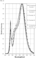
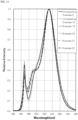
- light emission spectra of each of the light emitting devices when defining a maximum value of the light emission intensity as 1 are shown in FIGs. 3 to 11 .
- a maximum wavelength width (nm) at which the light emission intensity is 0.3 or more within a range of 480 nm or more and 680 nm or less when defining the maximum value of the light emission intensity as 1 was determined as a wavelength width I 1 0.3 at intensity of 0.3.
- a maximum wavelength width (nm) at which the light emission intensity is 0.3 or more within a range of 480 nm or more and 580 nm or less when defining the maximum value of the light emission intensity as 1 was determined as a wavelength width I 2 0.3 at intensity of 0.3.
- a light emission intensity at 480 nm when defining the light emission intensity of the light emitting element as 1 was determined as I 480 .
- Table 8 Chromaticity coordinate Color rendering index Correlated color temperature (K) Relative luminous flux (%) Wavelength width at intensity of 0.3 Intensity ratio (480 nm) I 480 Intensity ratio x y R a R9 480 to 580 nm I 2 0.3 480 to 680 nm I 1 0.3 I A /I B Comparative Example 1 0.312 0.328 82.1 10.9 6557 100.0 73 102 0.14 1.08 Comparative Example 2 0.312 0.328 89.5 24.6 6567 93.9 92 132 0.27 0.95 Example 1 0.312 0.328 87.3 12.9 6562 95.7 93 131 0.27 0.92 Example 2 0.312 0.328 87.1 12.4 6556 96.2 100 140 0.32 0.88 Example 3 0.312 0.328 87.4 18.4 6551 93.4 100 143 0.38 0.89 Example 4 0.312 0.328 86.5 10.7 6544 9
- the light emitting device of each of the Examples was wider than the light emitting device of each of the Comparative Examples with respect to the wavelength width I 1 0.3 of the light emitting emission spectra at 480 nm or more and 680 nm or less and the wavelength width I 2 0.3 of the light emitting emission spectra at 480 nm or more and 580 nm or less. As noted from FIGs.
- the wavelength width I 1 0.3 and the wavelength width I 2 0.3 in the light emission spectra of the light emitting device of each of the Examples having the respective correlated color temperatures were wider than the wavelength width I 1 0.3 and the wavelength width I 2 0.3 in the light emission spectra of the light emitting device of each of the Comparative Examples having the respective correlated color temperatures.
- the wavelength width I 1 0.3 in the range of 480 nm or more and 680 nm or less centering on 555 nm that is a peak of the typical luminous sensitivity at which the human eyes are especially easy to adjust the focus is expanded, and furthermore, the wavelength width I 2 0.3 in the range of 480 nm or more and 580 nm or less is expanded, it is possible to reduce the human eye fatigue under lighting of this light emitting device and to efficiently perform the human visual work.
- the light emitting device of each of the Examples is higher than the light emitting device of each of the Comparative Examples with respect to the intensity ratio I 480 to the peak intensity of the light emitting device. From these results, the light emitting device lowers the light emission intensity of the light emitting element emitting a blue light as a cause for glare, which is close to a wavelength region in the vicinity of 440 nm acting on an S cone that is one of human photoreceptor cells, and is able to reduce the human eye fatigue to be caused due to the glare.
- the stimulation to ipRGC that is one of human photoreceptor cells can be controlled, and as a result, the aforementioned light emitting device also has an effect for awakening a human being during visual work and maintaining the ability of concentration. Furthermore, a bluish-green component in the light emission spectra increases, and for example, it becomes possible to constitute a light emitting device capable of compensating a lowering of discrimination of a blue light with age of a human being.
- the light emitting device of each of the Examples is lower than the light emitting device of each of the Comparative Examples with respect to the ratio I A /I B . From these results, the light emitting devices of the Examples having the respective correlated color temperatures not only lower the light emission intensity of the light emitting element emitting a blue light which is close to a wavelength region in the vicinity of 440 nm acting on an S cone that is a human photoreceptor cell to reduce the human eye fatigue to be caused due to the glare but also lower the light emission intensity of a green light in a wavelength region in the vicinity of 535 nm acting on an M cone to reduce excessive stimulation to the M cone, whereby the human eye fatigue to be caused due to the glare can be more reduced.
- the light emitting device of an embodiment of the present invention is able to emit a light capable of reducing the human eye fatigue under lighting and having light emission spectra with excellent workability.
- the light emitting device of an embodiment of the present invention can be utilized as general lighting to be installed in indoors, such as offices, general households, commercial facilities, and factories, in-vehicle lighting, display, lighting for observation, warning light, outdoor security light, indicator light, and backlight for liquid crystal. Furthermore, a lighting fixture provided with this light emitting device can be provided.
Landscapes
- Chemical & Material Sciences (AREA)
- Inorganic Chemistry (AREA)
- Engineering & Computer Science (AREA)
- Materials Engineering (AREA)
- Organic Chemistry (AREA)
- Led Device Packages (AREA)
- Luminescent Compositions (AREA)
- Electroluminescent Light Sources (AREA)
Claims (7)
- Lichtemittierende Vorrichtung (100) mit einem fluoreszierenden Element (50), aufweisend:ein lichtemittierendes Element (10) mit einer Lichtemissions-Spitzenwellenlänge in einem Bereich von 440 nm oder mehr und 470 nm oder weniger,ein erstes fluoreszierendes Material (71) mit einer Lichtemissions-Spitzenwellenlänge in einem Bereich von 480 nm oder mehr und 518 nm oder weniger,ein zweites fluoreszierendes Material (72) mit einer Lichtemissions-Spitzenwellenlänge in einem Bereich von 510 nm oder mehr und weniger als 590 nm und mit einem x-Wert der Chromatizitätskoordinate bei CIE1931 in einem Bereich von 0,27 oder mehr und 0,40 oder weniger, undein drittes fluoreszierendes Material (73) mit einer Lichtemissions-Spitzenwellenlänge in einem Bereich von 590 nm oder mehr und 670 nm oder weniger, wobei,wenn ein Gehalt (Masse-%) des ersten fluoreszierenden Materials (71) relativ zu einer Gesamtmenge des ersten fluoreszierenden Materials, des zweiten fluoreszierenden Materials und des dritten fluoreszierenden Materials als MP1 definiert ist, ein Gehalt (Masse-%) des zweiten fluoreszierenden Materials (72) relativ zu der Gesamtmenge des ersten fluoreszierenden Materials, des zweiten fluoreszierenden Materials und des dritten fluoreszierenden Materials als MP2 definiert ist, eine maximale Wellenlängenbreite (nm), bei der, wenn ein Maximalwert einer Lichtemissionsintensität in einem Lichtemissionsspektrum der lichtemittierenden Vorrichtung als 1 definiert ist, eine Lichtemissionsintensität in einem Bereich von 480 nm oder mehr und 680 nm oder weniger bei 0,3 oder mehr liegt, als I1 0,3 definiert ist, und eine maximale Wellenlängenbreite (nm), bei der, wenn der Maximalwert der Lichtemissionsintensität in dem Lichtemissionsspektrum der lichtemittierenden Vorrichtung als 1 definiert ist, eine Lichtemissionsintensität in einem Bereich von 480 nm oder mehr und 580 nm oder weniger bei 0,3 oder mehr liegt, als I2 0,3 definiert ist, wobei in dem Fall, in dem eine korrelierte Farbtemperatur in jeden der folgenden Bereiche fällt, MP1, MP2, I1 0,3 und I2 0,3 jeweils Folgendes erfüllen:in dem Fall, in dem die korrelierte Farbtemperatur in einem Bereich von 2.000 K oder höher und niedriger als 2.800 K liegt, liegt MP1 in einem Bereich von 5 Masse-% oder mehr und 50 Masse-% oder weniger, liegt MP2 in einem Bereich von 40 Masse-% oder mehr und 90 Masse-% oder weniger, liegt I1 0,3 in einem Bereich von 177 nm oder mehr und 200 nm oder weniger, und liegt I2 0,3 in einem Bereich von 80 nm oder mehr und 100 nm oder weniger,in dem Fall, in dem die korrelierte Farbtemperatur in einem Bereich von 2.800 K oder höher und niedriger als 3.500 K liegt, liegt MP1 in einem Bereich von 5 Masse-% oder mehr und 50 Masse-% oder weniger, liegt MP2 in einem Bereich von 40 Masse-% oder mehr und 90 Masse-% oder weniger, liegt I1 0,3 in einem Bereich von 183 nm oder mehr und 200 nm oder weniger und liegt I2 0,3 in einem Bereich von 86 nm oder mehr und 100 nm oder weniger,in dem Fall, in dem die korrelierte Farbtemperatur in einem Bereich von 3.500 K oder höher und niedriger als 4.500 K liegt, liegt MP1 in einem Bereich von 5 Masse-% oder mehr und 65 Masse-% oder weniger, liegt MP2 in einem Bereich von 30 Masse-% oder mehr und 85 Masse-% oder weniger, liegt I1 0,3 in einem Bereich von 173 nm oder mehr und 200 nm oder weniger und liegt I2 0,3 in einem Bereich von 90 nm oder mehr und 100 nm oder weniger,in dem Fall, in dem die korrelierte Farbtemperatur in einem Bereich von 4.500 K oder höher und niedriger als 5.700 K liegt, liegt MP1 in einem Bereich von 5 Masse-% oder mehr und 50 Masse-% oder weniger, liegt MP2 in einem Bereich von 40 Masse-% oder mehr und 80 Masse-% oder weniger, liegt I1 0,3 in einem Bereich von 140 nm oder mehr und 180 nm oder weniger und liegt I2 0,3 in einem Bereich von 85 nm oder mehr und 100 nm oder weniger, undin dem Fall, in dem die korrelierte Farbtemperatur in einem Bereich von 5.700 K oder höher und 7.200 K oder niedriger liegt, liegt MP1 in einem Bereich von 5 Masse-% oder mehr und 50 Masse-% oder weniger, liegt MP2 in einem Bereich von 40 Masse-% oder mehr und 80 Masse-% oder weniger, und liegt I1 0,3 in einem Bereich von 110 nm oder mehr und 160 nm oder weniger und liegt I2 0,3 in einem Bereich von 81 nm oder mehr und 100 nm oder weniger,wobei das erste fluoreszierende Material (71) zumindest eines ist, das aus einem fluoreszierenden Material mit einer durch die folgende Formel (1A) dargestellten Zusammensetzung und einem fluoreszierenden Material mit einer durch die folgende Formel (1B) dargestellten Zusammensetzung ausgewählt ist:
(Sr1-vM1 v)4Al14O25:Eu (1A)
worin M1 zumindest ein Element ist, ausgewählt aus der Gruppe bestehend aus Mg, Ca, Ba und Zn, wobei gilt 0 ≤ v ≤ 5;
M2 8MgSi4O16X1 2:Eu (1B)
worin M2 zumindest ein Element ist, ausgewählt aus der Gruppe bestehend aus Ca, Sr, Ba und Zn; und X1 zumindest ein Element ist, ausgewählt aus der Gruppe bestehend aus F, Cl, Br und I,wobei das zweite fluoreszierende Material (72) ein fluoreszierendes Material mit einer durch die folgende Formel (2A) dargestellten Zusammensetzung ist:
(Ln1-aCea)3(Al1-bGab)5O12 (2A)
worin Ln zumindest ein Element ist, ausgewählt aus der Gruppe bestehend aus Y, Gd, Lu und Tb, wobei gilt 0,001 ≤ a ≤ 0,20, 0 ≤ b ≤ 1,0,wobei das dritte fluoreszierende Material (73) zumindest eines ist, das aus einem fluoreszierenden Material mit einer durch die folgende Formel (3A) dargestellten Zusammensetzung, einem fluoreszierenden Material mit einer durch die folgende Formel (3B) dargestellten Zusammensetzung und einem fluoreszierenden Material mit einer durch die folgende Formel (3C) dargestellten Zusammensetzung ausgewählt ist:
(Ca1-pSrp)AlSiN3: Eu (3A)
wobei gilt 0 ≤ p ≤ 1,0;
(Ca1-q-rSrqBar)2Si5N8:Eu (3B)
wobei gilt 0 ≤ q ≤ 1,0, 0 ≤ r ≤ 1,0, und (q + r) ≤ 1,0;
M4 kSi12-(m+n)Alm+nOnN16-n:Eu (3C)
worin M4 zumindest ein Element ist, ausgewählt aus der Gruppe bestehend aus Li, Mg, Ca, Sr, Y und einem lanthanoiden Element, (vorausgesetzt, dass La und Ce ausgeschlossen sind), wobei gilt 0 < k ≤ 2,0, 2,0 ≤ m ≤ 6,0 und 0 ≤ n ≤ 1,0,wobei, wenn die Lichtemissionsintensität bei 480 nm im Lichtemissionsspektrum der lichtemittierenden Vorrichtung als I480 definiert ist, wenn eine Lichtemissionsintensität des lichtemittierenden Elements (10) als 1 definiert ist, in dem Fall, in dem eine korrelierte Farbtemperatur der lichtemittierenden Vorrichtung in jeden der folgenden Bereiche fällt, I480 jeweils Folgendes erfüllt:in dem Fall, in dem die korrelierte Farbtemperatur in einem Bereich von 2.000 K oder höher und niedriger als 2.800K liegt, liegt I480 in einem Bereich von 0,30 oder mehr und 0,80 oder weniger;in dem Fall, in dem die korrelierte Farbtemperatur in einem Bereich von 2.800 K oder höher und niedriger als 3.500 K liegt, liegt I480 in einem Bereich von 0,25 oder mehr und 0,70 oder weniger;in dem Fall, in dem die korrelierte Farbtemperatur in einem Bereich von 3.500 K oder höher und niedriger als 4.500 K liegt, liegt I480 in einem Bereich von 0,20 oder mehr und 0,60 oder weniger;in dem Fall, in dem die korrelierte Farbtemperatur in einem Bereich von 4.500 K oder höher und niedriger als 5.700 K liegt, liegt I480 in einem Bereich von 0,17 oder mehr und 0,60 oder weniger; undin dem Fall, in dem die korrelierte Farbtemperatur in einem Bereich von 5.700 K oder höher und 7.200 K oder niedriger liegt, liegt I480 in einem Bereich von 0,16 oder mehr und 0,50 oder weniger, undwobei in dem Lichtemissionsspektrum der lichtemittierenden Vorrichtung (10), wenn eine Lichtemissionsintensität bei 535 nm als IA definiert ist, und ein Durchschnitt einer Lichtemissionsintensität bei 510 nm liegt und eine Lichtemissionsintensität bei 560 nm als IB definiert ist, ein Verhältnis von IA zu IB (IA/IB) in einem Bereich von 0,8 oder mehr und 0,96 oder weniger liegt. - Lichtem ittierende Vorrichtung (100) nach Anspruch 1, wobei das erste fluoreszierende Material (71) eine Lichtemissions-Spitzenwellenlänge in einem Bereich von 485 nm oder mehr und 518 nm oder weniger und eine Halbwertsbreite in einem Bereich von 30 nm oder mehr und 80 nm oder weniger aufweist.
- Lichtemittierende Vorrichtung (100) nach Anspruch 1 oder 2, wobei das zweite fluoreszierende Material (72) eine Lichtemissions-Spitzenwellenlänge in einem Bereich von 510 nm oder mehr und 550 nm oder weniger und eine Halbwertsbreite in einem Bereich von 20 nm oder mehr und 120 nm oder weniger aufweist.
- Lichtemittierende Vorrichtung (100) nach einem der Ansprüche 1 bis 3, wobei das dritte fluoreszierende Material (73) eine Lichtemissions-Spitzenwellenlänge in einem Bereich von 590 nm oder mehr und 630 nm oder weniger und eine Halbwertsbreite in einem Bereich von 5 nm oder mehr und 100 nm oder weniger aufweist.
- Lichtemittierende Vorrichtung (100) nach einem der Ansprüche 1 bis 4, wobei das lichtemittierende Element (10) eine Lichtemissionsspitze in einem Bereich von 440 nm oder mehr und 470 nm oder weniger und eine Halbwertsbreite in einem Bereich von 30 nm oder weniger aufweist.
- Lichtemittierende Vorrichtung (100) nach einem der Ansprüche 1 bis 5, wobei ein allgemeiner Farbwiedergabeindex Ra der lichtemittierenden Vorrichtung (100) 80 oder mehr beträgt.
- Beleuchtungskörper mit der lichtemittierenden Vorrichtung (100) nach einem der Ansprüche 1 bis 6.
Applications Claiming Priority (2)
| Application Number | Priority Date | Filing Date | Title |
|---|---|---|---|
| JP2018184537 | 2018-09-28 | ||
| JP2019170972A JP7303437B2 (ja) | 2018-09-28 | 2019-09-20 | 発光装置及びそれを備えた灯具 |
Publications (2)
| Publication Number | Publication Date |
|---|---|
| EP3628719A1 EP3628719A1 (de) | 2020-04-01 |
| EP3628719B1 true EP3628719B1 (de) | 2025-04-30 |
Family
ID=68069626
Family Applications (1)
| Application Number | Title | Priority Date | Filing Date |
|---|---|---|---|
| EP19199710.5A Active EP3628719B1 (de) | 2018-09-28 | 2019-09-26 | Lichtemittierende vorrichtung und mit derselben versehene leuchte |
Country Status (4)
| Country | Link |
|---|---|
| US (1) | US11133441B2 (de) |
| EP (1) | EP3628719B1 (de) |
| JP (1) | JP7486004B2 (de) |
| CN (1) | CN110970542B (de) |
Families Citing this family (4)
| Publication number | Priority date | Publication date | Assignee | Title |
|---|---|---|---|---|
| JP7185146B2 (ja) * | 2020-09-15 | 2022-12-07 | 日亜化学工業株式会社 | 発光装置 |
| JP7706899B2 (ja) | 2021-03-04 | 2025-07-14 | ソウル セミコンダクター カンパニー リミテッド | 白色光源の使用方法および白色光源 |
| EP4339509B1 (de) * | 2022-09-15 | 2025-03-19 | Nichia Corporation | Lichtemittierende vorrichtung für ein fahrzeug und fahrzeugbeleuchtungsvorrichtung |
| CN116589271B (zh) * | 2023-05-29 | 2025-08-19 | 江苏师范大学 | 一种激光照明用高热导、高显指复相荧光陶瓷及其制备方法 |
Family Cites Families (17)
| Publication number | Priority date | Publication date | Assignee | Title |
|---|---|---|---|---|
| US20060164005A1 (en) * | 2005-01-25 | 2006-07-27 | Chuan-Sheng Sun | Illumination apparatus having adjustable color temperature and method for adjusting the color temperature |
| US7443094B2 (en) * | 2005-03-31 | 2008-10-28 | Dowa Electronics Materials Co., Ltd. | Phosphor and manufacturing method of the same, and light emitting device using the phosphor |
| CN101195744A (zh) * | 2006-08-15 | 2008-06-11 | 大连路明科技集团有限公司 | 含氮化合物荧光材料及其制造方法和使用其的发光装置 |
| JPWO2009104652A1 (ja) * | 2008-02-18 | 2011-06-23 | 株式会社小糸製作所 | 白色発光装置及びこれを用いた車両用灯具 |
| CN102405538A (zh) * | 2009-08-26 | 2012-04-04 | 三菱化学株式会社 | 白色半导体发光装置 |
| EP2546897B1 (de) * | 2010-03-12 | 2019-01-23 | Kabushiki Kaisha Toshiba | Weisslichtbeleuchtungsvorrichtung |
| US20130143334A1 (en) | 2011-12-01 | 2013-06-06 | Hung Ta Trading Co., Ltd. | Method of enhancing color rendering index of a white led |
| CN108305929B (zh) | 2013-10-02 | 2021-02-05 | Glbtech株式会社 | 具有高显色性的白光发光装置 |
| KR101795740B1 (ko) | 2013-11-08 | 2017-11-08 | 루미마이크로 주식회사 | 발광장치 |
| JP6609554B2 (ja) | 2013-11-13 | 2019-11-20 | エルジー イノテック カンパニー リミテッド | 青緑色蛍光体、それを含む発光素子パッケージ及び照明装置 |
| KR101580739B1 (ko) | 2014-06-05 | 2015-12-28 | 엘지전자 주식회사 | 발광 장치 |
| JP2016154205A (ja) * | 2015-02-13 | 2016-08-25 | 日亜化学工業株式会社 | 発光装置 |
| JP6526603B2 (ja) | 2015-06-30 | 2019-06-05 | 日亜化学工業株式会社 | 発光装置 |
| US9735323B2 (en) * | 2015-06-30 | 2017-08-15 | Nichia Corporation | Light emitting device having a triple phosphor fluorescent member |
| JP6460040B2 (ja) * | 2016-03-04 | 2019-01-30 | 日亜化学工業株式会社 | 発光装置 |
| US10256374B2 (en) * | 2016-03-04 | 2019-04-09 | Nichia Corporation | Light emitting device |
| JP2017183522A (ja) | 2016-03-30 | 2017-10-05 | サンケン電気株式会社 | 発光装置 |
-
2019
- 2019-09-26 EP EP19199710.5A patent/EP3628719B1/de active Active
- 2019-09-26 CN CN201910922440.5A patent/CN110970542B/zh active Active
- 2019-09-27 US US16/586,883 patent/US11133441B2/en active Active
-
2023
- 2023-04-20 JP JP2023069356A patent/JP7486004B2/ja active Active
Also Published As
| Publication number | Publication date |
|---|---|
| US11133441B2 (en) | 2021-09-28 |
| EP3628719A1 (de) | 2020-04-01 |
| CN110970542B (zh) | 2024-07-19 |
| CN110970542A (zh) | 2020-04-07 |
| JP7486004B2 (ja) | 2024-05-17 |
| US20200105981A1 (en) | 2020-04-02 |
| JP2023109753A (ja) | 2023-08-08 |
Similar Documents
| Publication | Publication Date | Title |
|---|---|---|
| US12245445B2 (en) | White light source including LED and phosphors | |
| JP7303437B2 (ja) | 発光装置及びそれを備えた灯具 | |
| EP3628719B1 (de) | Lichtemittierende vorrichtung und mit derselben versehene leuchte | |
| EP3893286B1 (de) | Lichtemittierende vorrichtung | |
| US12123582B2 (en) | Systems and methods for providing tunable warm white light | |
| EP2905818B1 (de) | Weisslichtemittierende vorrichtung, beleuchtungsvorrichtung und beleuchtungsvorrichtung für die zahnmedizin | |
| US20210068222A1 (en) | Multi-channel systems for providing tunable light with high color rendering and biological effects | |
| JP7504980B2 (ja) | フルスペクトル白色発光デバイス | |
| JP2021536118A (ja) | フルスペクトル白色発光デバイス | |
| EP3567644B1 (de) | Weisslichtemittierende vorrichtung mit ultrahoher farbwiedergabe und kontrolliertem emissionsspektrum sowie beleuchtungsvorrichtung damit | |
| EP3733813A1 (de) | Lichtemittierende vorrichtung | |
| US20260101615A1 (en) | Light emitting device | |
| EP4130196A1 (de) | Lichtemissionsvorrichtung und leuchte damit | |
| US11437549B2 (en) | Light emitting device | |
| US20210259074A1 (en) | Systems and methods for providing tunable warm white light | |
| US20200260546A1 (en) | Multi-channel white light device for providing tunable white light with high color rendering | |
| US20260071734A1 (en) | Light emitting device and illumination device |
Legal Events
| Date | Code | Title | Description |
|---|---|---|---|
| PUAI | Public reference made under article 153(3) epc to a published international application that has entered the european phase |
Free format text: ORIGINAL CODE: 0009012 |
|
| STAA | Information on the status of an ep patent application or granted ep patent |
Free format text: STATUS: THE APPLICATION HAS BEEN PUBLISHED |
|
| AK | Designated contracting states |
Kind code of ref document: A1 Designated state(s): AL AT BE BG CH CY CZ DE DK EE ES FI FR GB GR HR HU IE IS IT LI LT LU LV MC MK MT NL NO PL PT RO RS SE SI SK SM TR |
|
| AX | Request for extension of the european patent |
Extension state: BA ME |
|
| STAA | Information on the status of an ep patent application or granted ep patent |
Free format text: STATUS: REQUEST FOR EXAMINATION WAS MADE |
|
| 17P | Request for examination filed |
Effective date: 20200917 |
|
| RBV | Designated contracting states (corrected) |
Designated state(s): AL AT BE BG CH CY CZ DE DK EE ES FI FR GB GR HR HU IE IS IT LI LT LU LV MC MK MT NL NO PL PT RO RS SE SI SK SM TR |
|
| STAA | Information on the status of an ep patent application or granted ep patent |
Free format text: STATUS: EXAMINATION IS IN PROGRESS |
|
| 17Q | First examination report despatched |
Effective date: 20220824 |
|
| P01 | Opt-out of the competence of the unified patent court (upc) registered |
Effective date: 20230522 |
|
| GRAP | Despatch of communication of intention to grant a patent |
Free format text: ORIGINAL CODE: EPIDOSNIGR1 |
|
| STAA | Information on the status of an ep patent application or granted ep patent |
Free format text: STATUS: GRANT OF PATENT IS INTENDED |
|
| RIC1 | Information provided on ipc code assigned before grant |
Ipc: H10H 20/851 20250101ALI20250106BHEP Ipc: C09K 11/77 20060101ALI20250106BHEP Ipc: C09K 11/08 20060101AFI20250106BHEP |
|
| INTG | Intention to grant announced |
Effective date: 20250117 |
|
| GRAS | Grant fee paid |
Free format text: ORIGINAL CODE: EPIDOSNIGR3 |
|
| GRAA | (expected) grant |
Free format text: ORIGINAL CODE: 0009210 |
|
| STAA | Information on the status of an ep patent application or granted ep patent |
Free format text: STATUS: THE PATENT HAS BEEN GRANTED |
|
| AK | Designated contracting states |
Kind code of ref document: B1 Designated state(s): AL AT BE BG CH CY CZ DE DK EE ES FI FR GB GR HR HU IE IS IT LI LT LU LV MC MK MT NL NO PL PT RO RS SE SI SK SM TR |
|
| REG | Reference to a national code |
Ref country code: CH Ref legal event code: EP Ref country code: GB Ref legal event code: FG4D |
|
| REG | Reference to a national code |
Ref country code: DE Ref legal event code: R096 Ref document number: 602019069264 Country of ref document: DE |
|
| REG | Reference to a national code |
Ref country code: IE Ref legal event code: FG4D |
|
| REG | Reference to a national code |
Ref country code: NL Ref legal event code: MP Effective date: 20250430 |
|
| REG | Reference to a national code |
Ref country code: AT Ref legal event code: MK05 Ref document number: 1790028 Country of ref document: AT Kind code of ref document: T Effective date: 20250430 |
|
| PG25 | Lapsed in a contracting state [announced via postgrant information from national office to epo] |
Ref country code: ES Free format text: LAPSE BECAUSE OF FAILURE TO SUBMIT A TRANSLATION OF THE DESCRIPTION OR TO PAY THE FEE WITHIN THE PRESCRIBED TIME-LIMIT Effective date: 20250430 Ref country code: FI Free format text: LAPSE BECAUSE OF FAILURE TO SUBMIT A TRANSLATION OF THE DESCRIPTION OR TO PAY THE FEE WITHIN THE PRESCRIBED TIME-LIMIT Effective date: 20250430 Ref country code: PT Free format text: LAPSE BECAUSE OF FAILURE TO SUBMIT A TRANSLATION OF THE DESCRIPTION OR TO PAY THE FEE WITHIN THE PRESCRIBED TIME-LIMIT Effective date: 20250901 |
|
| PGFP | Annual fee paid to national office [announced via postgrant information from national office to epo] |
Ref country code: DE Payment date: 20250730 Year of fee payment: 7 |
|
| REG | Reference to a national code |
Ref country code: LT Ref legal event code: MG9D |
|
| PG25 | Lapsed in a contracting state [announced via postgrant information from national office to epo] |
Ref country code: GR Free format text: LAPSE BECAUSE OF FAILURE TO SUBMIT A TRANSLATION OF THE DESCRIPTION OR TO PAY THE FEE WITHIN THE PRESCRIBED TIME-LIMIT Effective date: 20250731 Ref country code: NO Free format text: LAPSE BECAUSE OF FAILURE TO SUBMIT A TRANSLATION OF THE DESCRIPTION OR TO PAY THE FEE WITHIN THE PRESCRIBED TIME-LIMIT Effective date: 20250730 |
|
| PG25 | Lapsed in a contracting state [announced via postgrant information from national office to epo] |
Ref country code: NL Free format text: LAPSE BECAUSE OF FAILURE TO SUBMIT A TRANSLATION OF THE DESCRIPTION OR TO PAY THE FEE WITHIN THE PRESCRIBED TIME-LIMIT Effective date: 20250430 Ref country code: PL Free format text: LAPSE BECAUSE OF FAILURE TO SUBMIT A TRANSLATION OF THE DESCRIPTION OR TO PAY THE FEE WITHIN THE PRESCRIBED TIME-LIMIT Effective date: 20250430 |
|
| PG25 | Lapsed in a contracting state [announced via postgrant information from national office to epo] |
Ref country code: BG Free format text: LAPSE BECAUSE OF FAILURE TO SUBMIT A TRANSLATION OF THE DESCRIPTION OR TO PAY THE FEE WITHIN THE PRESCRIBED TIME-LIMIT Effective date: 20250430 |
|
| PGFP | Annual fee paid to national office [announced via postgrant information from national office to epo] |
Ref country code: GB Payment date: 20250807 Year of fee payment: 7 |
|
| PG25 | Lapsed in a contracting state [announced via postgrant information from national office to epo] |
Ref country code: HR Free format text: LAPSE BECAUSE OF FAILURE TO SUBMIT A TRANSLATION OF THE DESCRIPTION OR TO PAY THE FEE WITHIN THE PRESCRIBED TIME-LIMIT Effective date: 20250430 |
|
| PG25 | Lapsed in a contracting state [announced via postgrant information from national office to epo] |
Ref country code: AT Free format text: LAPSE BECAUSE OF FAILURE TO SUBMIT A TRANSLATION OF THE DESCRIPTION OR TO PAY THE FEE WITHIN THE PRESCRIBED TIME-LIMIT Effective date: 20250430 |
|
| PGFP | Annual fee paid to national office [announced via postgrant information from national office to epo] |
Ref country code: FR Payment date: 20250808 Year of fee payment: 7 |
|
| PG25 | Lapsed in a contracting state [announced via postgrant information from national office to epo] |
Ref country code: RS Free format text: LAPSE BECAUSE OF FAILURE TO SUBMIT A TRANSLATION OF THE DESCRIPTION OR TO PAY THE FEE WITHIN THE PRESCRIBED TIME-LIMIT Effective date: 20250731 |
|
| PG25 | Lapsed in a contracting state [announced via postgrant information from national office to epo] |
Ref country code: IS Free format text: LAPSE BECAUSE OF FAILURE TO SUBMIT A TRANSLATION OF THE DESCRIPTION OR TO PAY THE FEE WITHIN THE PRESCRIBED TIME-LIMIT Effective date: 20250830 |
|
| PG25 | Lapsed in a contracting state [announced via postgrant information from national office to epo] |
Ref country code: LV Free format text: LAPSE BECAUSE OF FAILURE TO SUBMIT A TRANSLATION OF THE DESCRIPTION OR TO PAY THE FEE WITHIN THE PRESCRIBED TIME-LIMIT Effective date: 20250430 |
|
| PG25 | Lapsed in a contracting state [announced via postgrant information from national office to epo] |
Ref country code: DK Free format text: LAPSE BECAUSE OF FAILURE TO SUBMIT A TRANSLATION OF THE DESCRIPTION OR TO PAY THE FEE WITHIN THE PRESCRIBED TIME-LIMIT Effective date: 20250430 Ref country code: SM Free format text: LAPSE BECAUSE OF FAILURE TO SUBMIT A TRANSLATION OF THE DESCRIPTION OR TO PAY THE FEE WITHIN THE PRESCRIBED TIME-LIMIT Effective date: 20250430 |
|
| PG25 | Lapsed in a contracting state [announced via postgrant information from national office to epo] |
Ref country code: CZ Free format text: LAPSE BECAUSE OF FAILURE TO SUBMIT A TRANSLATION OF THE DESCRIPTION OR TO PAY THE FEE WITHIN THE PRESCRIBED TIME-LIMIT Effective date: 20250430 |
|
| PG25 | Lapsed in a contracting state [announced via postgrant information from national office to epo] |
Ref country code: EE Free format text: LAPSE BECAUSE OF FAILURE TO SUBMIT A TRANSLATION OF THE DESCRIPTION OR TO PAY THE FEE WITHIN THE PRESCRIBED TIME-LIMIT Effective date: 20250430 |
|
| PG25 | Lapsed in a contracting state [announced via postgrant information from national office to epo] |
Ref country code: RO Free format text: LAPSE BECAUSE OF FAILURE TO SUBMIT A TRANSLATION OF THE DESCRIPTION OR TO PAY THE FEE WITHIN THE PRESCRIBED TIME-LIMIT Effective date: 20250430 Ref country code: SK Free format text: LAPSE BECAUSE OF FAILURE TO SUBMIT A TRANSLATION OF THE DESCRIPTION OR TO PAY THE FEE WITHIN THE PRESCRIBED TIME-LIMIT Effective date: 20250430 |
|
| PG25 | Lapsed in a contracting state [announced via postgrant information from national office to epo] |
Ref country code: IT Free format text: LAPSE BECAUSE OF FAILURE TO SUBMIT A TRANSLATION OF THE DESCRIPTION OR TO PAY THE FEE WITHIN THE PRESCRIBED TIME-LIMIT Effective date: 20250430 |
|
| REG | Reference to a national code |
Ref country code: DE Ref legal event code: R097 Ref document number: 602019069264 Country of ref document: DE |
|
| PLBE | No opposition filed within time limit |
Free format text: ORIGINAL CODE: 0009261 |
|
| STAA | Information on the status of an ep patent application or granted ep patent |
Free format text: STATUS: NO OPPOSITION FILED WITHIN TIME LIMIT |
|
| REG | Reference to a national code |
Ref country code: CH Ref legal event code: L10 Free format text: ST27 STATUS EVENT CODE: U-0-0-L10-L00 (AS PROVIDED BY THE NATIONAL OFFICE) Effective date: 20260311 |
|
| 26N | No opposition filed |
Effective date: 20260202 |