EP3628762A2 - Gestrickte handschuhe und verfahren zur herstellung davon - Google Patents
Gestrickte handschuhe und verfahren zur herstellung davon Download PDFInfo
- Publication number
- EP3628762A2 EP3628762A2 EP19195222.5A EP19195222A EP3628762A2 EP 3628762 A2 EP3628762 A2 EP 3628762A2 EP 19195222 A EP19195222 A EP 19195222A EP 3628762 A2 EP3628762 A2 EP 3628762A2
- Authority
- EP
- European Patent Office
- Prior art keywords
- component
- glove
- knitted
- thumb
- finger
- Prior art date
- Legal status (The legal status is an assumption and is not a legal conclusion. Google has not performed a legal analysis and makes no representation as to the accuracy of the status listed.)
- Withdrawn
Links
Images



Classifications
-
- D—TEXTILES; PAPER
- D04—BRAIDING; LACE-MAKING; KNITTING; TRIMMINGS; NON-WOVEN FABRICS
- D04B—KNITTING
- D04B7/00—Flat-bed knitting machines with independently-movable needles
- D04B7/30—Flat-bed knitting machines with independently-movable needles specially adapted for knitting goods of particular configuration
- D04B7/32—Flat-bed knitting machines with independently-movable needles specially adapted for knitting goods of particular configuration tubular goods
- D04B7/34—Flat-bed knitting machines with independently-movable needles specially adapted for knitting goods of particular configuration tubular goods gloves
-
- D—TEXTILES; PAPER
- D04—BRAIDING; LACE-MAKING; KNITTING; TRIMMINGS; NON-WOVEN FABRICS
- D04B—KNITTING
- D04B1/00—Weft knitting processes for the production of fabrics or articles not dependent on the use of particular machines; Fabrics or articles defined by such processes
- D04B1/22—Weft knitting processes for the production of fabrics or articles not dependent on the use of particular machines; Fabrics or articles defined by such processes specially adapted for knitting goods of particular configuration
- D04B1/24—Weft knitting processes for the production of fabrics or articles not dependent on the use of particular machines; Fabrics or articles defined by such processes specially adapted for knitting goods of particular configuration wearing apparel
- D04B1/28—Weft knitting processes for the production of fabrics or articles not dependent on the use of particular machines; Fabrics or articles defined by such processes specially adapted for knitting goods of particular configuration wearing apparel gloves
-
- A—HUMAN NECESSITIES
- A41—WEARING APPAREL
- A41D—OUTERWEAR; PROTECTIVE GARMENTS; ACCESSORIES
- A41D19/00—Gloves
- A41D19/015—Protective gloves
- A41D19/01505—Protective gloves resistant to mechanical aggressions, e.g. cutting. piercing
-
- D—TEXTILES; PAPER
- D04—BRAIDING; LACE-MAKING; KNITTING; TRIMMINGS; NON-WOVEN FABRICS
- D04B—KNITTING
- D04B15/00—Details of, or auxiliary devices incorporated in, weft knitting machines, restricted to machines of this kind
- D04B15/66—Devices for determining or controlling patterns ; Program-control arrangements
- D04B15/68—Devices for determining or controlling patterns ; Program-control arrangements characterised by the knitting instruments used
- D04B15/74—Pattern drums
-
- A—HUMAN NECESSITIES
- A41—WEARING APPAREL
- A41D—OUTERWEAR; PROTECTIVE GARMENTS; ACCESSORIES
- A41D19/00—Gloves
- A41D19/01—Gloves with undivided covering for all four fingers, i.e. mittens
-
- A—HUMAN NECESSITIES
- A41—WEARING APPAREL
- A41D—OUTERWEAR; PROTECTIVE GARMENTS; ACCESSORIES
- A41D19/00—Gloves
- A41D19/04—Appliances for making gloves; Measuring devices for glove-making
-
- A—HUMAN NECESSITIES
- A41—WEARING APPAREL
- A41D—OUTERWEAR; PROTECTIVE GARMENTS; ACCESSORIES
- A41D2500/00—Materials for garments
- A41D2500/10—Knitted
-
- D—TEXTILES; PAPER
- D10—INDEXING SCHEME ASSOCIATED WITH SUBLASSES OF SECTION D, RELATING TO TEXTILES
- D10B—INDEXING SCHEME ASSOCIATED WITH SUBLASSES OF SECTION D, RELATING TO TEXTILES
- D10B2501/00—Wearing apparel
- D10B2501/04—Outerwear; Protective garments
- D10B2501/041—Gloves
Definitions
- the present invention relates to knitted gloves for protecting the hands of the wearer against physical hazards, such as abrasion, cuts or puncturing,
- the invention further, relates to methods of making such knitted gloves.
- Personal protective gloves are used in many areas of activity, for instance, industry, agriculture and leisure activities. Gloves typically have four finger stalls to cover each of the four fingers and a thumb stall to cover the thumb, but may also be mittens which have a thumb stall and fewer than four finger stalls, usually one to cover all four fingers together. Gauntlets are gloves, including mittens, which have extended wrist-covering areas to protect the arms. Gloves, whether typical style, mitten style, or gauntlet style, all have a thumb stall separate from the stall which encloses the forefinger to allow the wearer to grip objects. Gloves also have a palm region and the inside edge of this, i.e.
- the edge which joins the edge of the forefinger stall to the base of the thumb stall is generally known as the thumb crotch area of a glove.
- Protective gloves are essential items in hazardous handling environments where an important property of the glove is resistance to physical harm caused by abrasion, cutting, or puncturing. Protective gloves must also be comfortable to maximise the willingness of handlers to wear the gloves during potentially dangerous handling procedures.
- the useful life of a glove depends very much on the strength of the thumb crotch area since this is subjected to stress due to the constant flexing of the thumb and forefinger to grab hold of, and grip, objects. Consequently, it is beneficial to increase the strength of the thumb crotch area so as to increase the safety of the wearer and to increase the useful working life of the glove.
- a simple, previously-known method to increase the strength of the thumb crotch is with the use of a sewing machine to add a line of lock stitch, commonly known as Overlock stitching, around the crotch edge, around the thumb crotch palm edge and, optionally, up the forefinger of cut and sewn liners and machine-knitted liners. This additional sewing runs along the edge of the forefinger and then down around the thumb crotch and up the inside edge of the thumb.
- a sewing machine to add a line of lock stitch, commonly known as Overlock stitching, around the crotch edge, around the thumb crotch palm edge and, optionally, up the forefinger of cut and sewn liners and machine-knitted liners.
- US 7,089,600 describes a process which involves the double polymer coating of the forefinger to thumb crotch region of a glove.
- US patents Nos. 6,962,064 , 7,213,419 , 7,555,921 and 7,908,891 describe the knitting of gloves with variable knitted regions.
- the provision of a polymer coating containing a hard particulate filler to a knitted glove liner or shell by a dip coating method is described in US 9,456,645 .
- Knitted gloves for the purposes described above, are currently made using flat knitting machines that use a number of needles in the form of a needle array in a needle bed and a single feed of yarn, or yarns.
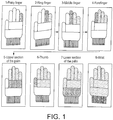
- Typical gloves comprise eight basic component knitted sections to form the finished glove. These eight components include one component for each of the four fingers and thumb, two components for the palm including an upper section and a lower section, and finally one component for the wrist area. All of these sections are essentially knitted tubular or conical sections that join to each other fashioning the general anatomical shape of a hand. Conventional knitting processes use a flat knitting machine to knit each of these areas in a particular sequence.
- the sequence of knitting the components follows with one finger at a time, beginning with the little finger and continuing on through the ring and middle finger to the forefinger. After each finger is knitted using only selected needles in the needle knitting bed, the knitting process for each finger is stopped, and yarn is cut and bound. The finished knitted finger or component is held in place by holders, weighted down by sinkers. The next finger is then knitted sequentially one at a time using a different set of needles in the needle bed. When all four fingers are knitted in this fashion, the knitting machine then knits the upper section of the palm, picking stitches from each of the previously knit four fingers. After knitting an appropriate length of the upper palm, the thumb portion is then initiated. Next the lower section of the palm is knitted using all of the needles across the needle bed.
- the knitting machine knits the wrist component to the desired length.
- the sequence of knitting the components of the glove is illustrated in Fig 1 .
- the number of knitted courses down each of the knitted components is controlled by a computer program in the knitting machine where the number of courses can be varied to suit the required lengths of the components. It is well known by those practised in the art as how to set up the knitting machines to knit the required gloves.
- the typical flat knitting machine has two stationary knitting beds arranged in an inverted V formation. Latch needles slide in the tricks during the knitting action. For a needle to be selected for knitting, the butt of the needle is caused to protrude out of the needle bed.
- the needles are controlled as they pass through the tracks formed by angular cams of a bidirectional cam system attached to the underside of a carriage that transverses the bed in a reciprocating manner across the machine width on guide rails.
- needles are selected for use in knitting using needles which are located in the knitting bed.
- a drum which is cylindrical, and rotatable about its central axis and which has a plurality of lateral grooves in its outer surface which are parallel to each other and to the axis of rotation of the cylinder is located beneath the needle bed.
- the drum has a number of needle selection pins or rods laid down in the grooves of the drum. The length of the pin for each portion of the glove to be knitted (fingers, thumb, palms and wrist) is different and it defines the number of needles to be activated for each portion. This controls the width of the knitted component.
- the needle bed comprises a plurality of needles ready for activation in the knitting process.
- Each needle is retained slidably in a needle jack which is itself retained in a control jack.
- the control jacks are located above the needle selection drum.
- the control jack has a butt which extends into a groove of the needle selection drum. If the groove does not contain a needle selection pin, the position of the control jack is not altered and the needle retained is not brought into action in the knitting process. If the drum rotates to present a groove, to the control jack butt, which does contain a needle selection pin, the needle selection pin in the groove of the drum pushes up the control jack in which the needle is secured.
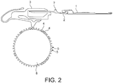
- Fig. 2 shows a cross sectional view of the needle bed, wherein a needle 1 is secured to needle jack 2 retained in control jack 3.
- a pin 4 located in a groove 5 of needle selection drum 6 this causes the needle jack butt 7 to be raised.
- the latch of the needle opens, thus allowing the needle hook to hold yarn. The needle then moves downward taking the yarn with it.
- the present invention provides a knitted glove comprising at least one finger component, an upper palm component, a thumb component, a lower palm component, and a wrist component wherein each of the components comprises courses and each course is made of stitches, wherein each of the courses of the upper palm component includes a tuck knit stitch adjacent the upper palm inner edge and each of the courses of the thumb component includes a tuck knit stitch adjacent the thumb inner edge, such that the glove has a tuck knitted ridge along the upper palm inner edge, around the thumb crotch and along the thumb inner edge.
- the invention also provides a method of making a knitted glove comprising knitting, in sequence at least one finger component, an upper palm component, a thumb component, a lower palm component, and a wrist component, wherein each of the components comprises knitted courses and each course is made of stitches, wherein each course of the upper palm component is knitted to include a tuck knit stitch in the course adjacent the upper palm inner edge and each course of the thumb component is knitted to include a tuck knit stitch in the course adjacent the thumb inner edge, such that a tuck knit ridge is created along the upper palm inner edge, around the thumb crotch and along the thumb inner edge as the upper palm component and the thumb component are knitted sequentially.
- the knitted glove of the invention comprises at least one finger component, i.e. at least one component for enclosing the fingers of the wearer's hand.
- the four fingers of the wearer's hand can be enclosed in a single component and a glove providing a single enclosure for all four fingers of a wearer's hand is generally called a mitten as mentioned above.
- the four fingers of a wearer's hand may each be enclosed separately in a conventional glove which has four separate finger components, In either case, the index finger of the wearer's hand is enabled to interact with the thumb so as to allow a holding or gripping action principally involving the thumb and the index finger of the hand.
- a knitted fabric consists of a number of consecutive rows or courses of intermeshing of loops of a yarn (stitches).
- Each of the components of the knitted glove of the invention comprises a plurality of courses.
- the length of a component is determined by the number of courses across the width of the fabric. This number will be determined by the size of the garment to be produced,
- the knitted glove of the invention comprises an upper palm component and a thumb component.
- the upper palm component is the component to which the at least one finger component is adjoined,
- the upper palm component has an inner edge which adjoins the thumb crotch area and the edge of the glove adjacent the index finger position in the finger component and, also, an outer edge which adjoins the edge of the glove adjacent the little finger position in the finger component.
- the upper palm inner edge is on the thumb side of the glove.
- Each of the courses or rows of the upper palm component includes a tuck knit stitch adjacent the upper palm inner edge.
- tuck knit stitch we mean a stitch which knits two consecutive courses or rows together. The presence of a tuck knit stitch in each of the courses or rows of the upper palm component adjacent the upper palm inner edge results in a ridge that projects outwards along the upper palm inner edge.
- the thumb component has an inner edge which faces the upper palm inner edge and the edge of the glove adjacent the index finger position in the finger component and an outer edge.
- Each of the courses or rows of the thumb component of the glove includes a tuck knit stitch adjacent the thumb inner edge.
- the result of the presence of the tuck knit stitches adjacent the thumb inner edge is that a tuck knit ridge extends from the upper palm inner edge, around the thumb crotch and along the thumb inner edge. This ridge provides increased strength to the glove in the thumb crotch area which not only improves the wear resistance and, thus, the working life of the glove but also improves the safety afforded to the wearer by the glove.
- each of the courses of at least the lower region of the finger component which encloses the index finger of the wearer also includes a tuck knit stitch adjacent the edge of the finger component which is closest to the position of the index finger.
- each of the courses or rows of at least a lower region of the finger component adjacent the upper palm component includes a tuck knit stitch adjacent the index finger edge, such that the glove has a tuck knit ridge along the index finger edge of the finger component.
- the tuck knit ridge extends continuously down from at least a lower region of the index finger edge, along the upper palm inner edge, around the thumb crotch and along the thumb inner edge. The continuous nature of such a ridge gives a glove increased strength and resistance to wear.
- each of the courses or rows of at least a lower region of the index finger component adjacent the upper palm component preferably also includes a tuck knit stitch adjacent the outer edge of the index finger component such that the glove has a tuck knit ridge along the outer edge of the index finger component.
- the glove has a tuck knit ridge that extends continuously down from at least a lower region of the outer edge of the index finger component, along the upper palm inner edge, around the thumb crotch and along the thumb inner edge. The continuous nature of such a ridge gives a glove increased strength and resistance to wear.
- the finger component preferably has a tuck knit ridge along at least a lower region of the index finger edge. This is a consequence of each of the courses or rows of at least a lower region of the finger component having a tuck stitch which stitches together consecutive courses or rows in the fabric.
- at least a lower region we mean at least one tenth ( 1 / 10 ) of the length of the finger component from the bottom of the finger component, preferably at least one eighth (1 ⁇ 8), more preferably at least one quarter and most preferably at least one half of the length of the finger component measured from the bottom of the finger component.
- the glove of the invention having a tuck knit ridge along upper palm edge, around the thumb crotch and along the thumb inner edge, whether or not it also has a tuck knit ridge along at least a lower region of the index finger edge as described above, also has a tuck knit ridge along the edge of the heel of the hand (i.e. along the outside edge of the palm/hand).
- a tuck knit ridge in such an embodiment, extends along at least part of the outer edge of the glove, lying between the base of the little finger component and the wrist component.
- the glove of the present invention may be knitted from yarn comprising natural fibres, synthetic fibres or mixtures thereof.
- the yarns used to knit the glove may be spun yarns, textured filament yarns or multicomponent composite yarns.
- compositions that may be used as, or in, yarns include cotton, nylon fibres, polyester fibres, high performance polyethylene (HPPE) fibres or aramid or other fire-resistant fibres that can be used to knit gloves.
- the knitted gloves of the invention will additionally have a coating on at least part of the glove of an elastomeric polymer composition, for instance a natural or synthetic rubber composition.
- a coating may be provided on any, or all, of the fingers, thumb, thumb crotch, upper and/or lower palm in order to provide glove surfaces that have water or oil-resistance, extra strength or improved gripping or holding properties.
- the invention further provides a method of making a knitted glove, as stated above.
- the method comprises the steps of knitting, in sequence, at least one finger component, an upper palm component, a thumb component, a lower palm component, and a wrist component, wherein each course of the upper palm component is knitted to include a tuck knit stitch in the course adjacent the upper palm inner edge and each course of the thumb component is knitted to include a tuck knit stitch in the course adjacent the thumb inner edge, such that a tuck knit ridge is created along the upper palm inner edge, around the thumb crotch and along the thumb inner edge as the upper palm component and the thumb component are knitted sequentially.
- Each of the components is knitted in sequence, as mentioned above and, generally, as illustrated in Fig.1 .
- the knitting machine used will, first, knit the one or more finger components. If only one finger component is required, i.e. in the production of a mitten, then after that component has been knitted the knitting sequence continues with the knitting of the upper palm component. If more than one finger component is to be knitted, the sequence begins with the knitting of the finger components, starting with the finger component furthest away from the thumb. The knitting sequence continues with the knitting of the finger components moving closer to the thumb, one finger component at a time. Thus, in the case of a typical glove with four finger components, the sequence begins with the component for the little finger, continuing on through the third finger and middle finger to the index finger.
- each finger component is knitted using the needles selected for this, the knitting process for each finger component is stopped and, typically, the yarn is cut and bound.
- the finished knitted finger component is held in place by holders, weighted down by sinkers and, if further finger components are required, these are knitted sequentially one at a time using a different set of needles in the needle bed.
- the knitting machine then knits the upper palm component, picking stitches from each of the previously knit finger components.
- the thumb component is then initiated.
- the lower palm component is knitted using all of the needles across the needle bed. Finally, the knitting machine knits the wrist component to the desired length.
- the gloves of the invention can be knitted using a flat knitting machine which has a needle selection drum located beneath the knitting bed.
- a needle selection drum located beneath the knitting bed.
- the needle selection drum in such machines has a plurality of parallel grooves in the direction of the drum axis.
- Needle selection pins which are rod-like, of various lengths depending on the knitting requirements, are located in the grooves in a predetermined arrangement pattern.
- a two-dimensional representation of the position of needle selection pins in the grooves of the cylindrical needle selection drum in the manufacture of the four-fingered grove shown in Fig. 1 is shown in Fig. 3 . As indicated in Fig.
- the knitting process for the glove begins with the pin arrangement A (the little finger) and sequentially proceeds through B (Ring finger), C (middle finger) to D (forefinger).
- Fig. 3 E represents the pin arrangement for the knitting of the upper palm component of the grove
- F represents the pin arrangement for the thumb component
- G is the arrangement for the lower palm component
- H indicates the pin arrangement for the wrist component of the glove.
- numbers are shown for each of the pins and these correspond to the numbers of courses to be knitted for each pin. Beneath the pin arrangement for the thumb component is shown the pin arrangement for knitting the lower palm component of the glove and, beneath this, the pin arrangement for knitting the wrist component of the glove.
- the length of the round pin, provided in the grooves of the needle selection drum of the knitting machine, for each portion of the glove (fingers, thumb, palms, wrist) is different and it defines the number of needles to be activated for each portion. This controls the width of the knitted component.
- the drum is rotated by one pitch corresponding to the interval between one groove and the next and the pins located in this next groove are brought into play.
- a needle selection pin in the drum groove pushes up a control jack in which the knitting needle is secured, the needle jack butt of the needle jack is caused to protrude from an opening in the needle bed.
- the control jack when pushed up by the pin, pushes the needle jack butt upwards and out of the needle bed. As a carriage moves across the knitting bed, it contacts all needle jack butts protruding out of the needle bed and so engages those needles in the knitting process. When the needle moves up the knitting bed, a latch on the hooked end of the needle opens which allows the needle to hook and hold yarn and, subsequently, to pull the yarn down as it moves downwards. The yarn is then pressed by sinkers to complete the stitch and hence advance the fabric formation process.
- One first, alternative, modification of the knitting machine components which results in the knitting of gloves according to the invention requires i) a change to the diameters of the needle selection pins located in the needle selection drum for the upper palm component and for the thumb component; and ii) a change to the diameter of the set-up cam control lever roller which is located in the knitting front carriage.
- the needle selection pin for the upper palm section should be replaced by two new pins (a) and (b); a first (a) having a diameter increased, from the conventional diameter size of 2.5mm, to 3.07mm-3.08mm and a second (b) having a diameter reduced, from the conventional diameter size of 2.5mm, to 2mm.
- the base needle selection pin for the thumb section should be replaced by two new pins (c) and (d); a first (c) having a diameter increased, from the conventional diameter size of 2.5mm, to 3.07-3.08mm and a second (d) having a diameter reduced, from the conventional diameter size of 2.5mm, to 2mm.
- a two-dimensional representation of a needle selection pin arrangement which shows the modification to the number and diameters of pins for the knitting of the upper palm and thumb component is shown in Fig. 4 .
- the increased height of the needle selection pins (a) and (c) in the drum grooves will have the effect of raising the needle second in from the edge of the components directly above higher than is normal in the knitting process which causes both back bed needle and front bed needle to cross and create a tuck stitch.
- the set-up cam which is located in the knitting front carriage, is capable of movement upwards and downwards. When the set-up cam is in the upward position the cam works and when it is in the downward position the cam does not work.
- the motion of the set-up cam is controlled by a computer.
- the set-up cam is normally set to the working position only during finger tip knitting to create a tuck knit at those areas so as to close the finger tips and to create a tucked crotch between successive finger components.
- the modification of the set-up cam required (in combination with the pin modification discussed above) to enable the machine to create a tuck knit ridge as described involves a reduction of the diameter of the set-up cam control lever roller from the normal size of 5mm to 3.5-3.8mm.
- a second, alternative, modification of the knitting machine components that enables the machine to create a tuck knit ridge as described involves a principle similar to that described above in that the needle is caused to raise and the effect of the set-up cam is reduced.
- This modification requires a combination of an increase in the height of the control jack butt on the control jack, a reduction in the height of the set-up cam control bar, and a reduction in the diameter of the needle selection pin that slots into the grooves of the selection drum.
- the standard (i.e. normal) height of the butt on the control jack, with finer gauges above 10, is 3mm.
- the height of the butt for such gauges should be increased by 0.1 to 4mm, preferably by 0.5 to 2mm and more preferably by 1mm.
- the butt on the control jack as supplied is 4mm high.
- the height of the butt for such gauges should also be increased by 0.1 to 4mm, preferably by 0.5 to 2mm and more preferably by 1mm.
- the second part of this modification involves resetting the height of the set-up cam control bar, as mentioned above.
- the set-up cam control bar in a machine set up to knit conventional gloves governs the working of the finger tip knitting end and the finger crotch areas.
- the needles at the edge of the workpiece are activated to form tuck knit stitches.
- the standard height of the set-up cam bar is 16mm.
- the height of the set-up cam bar should be reduced along the whole of its length by 1 to 8mm, preferably by 2 to 4mm and more preferably by 3mm, where the set-up cam bar has a height along the whole of its length of 13mm.
- the third part of this modification involves a reduction in the diameter of the needle selection pin that slots into the grooves of the needle selection drum.
- the standard needle selection pin With higher gauge knitting needles (10, 13, 15 and 18 gauges), the standard needle selection pin has a diameter of 2.5mm.
- the diameter of the needle selection pin will be 0.1 to 1.8mm less than the standard diameter, preferably 0.5 to 1.5mm less and more preferably 1mm less than the standard diameter where the diameter of the pin will be 1mm.
- the standard diameter of the needle selection pin, as supplied is 3mm.
- the diameter of the needle selection pin will be 0.1 to 1.8mm less than the standard diameter, preferably 0.5 to 2mm less and more preferably 1mm where the needle selection pin will have a diameter of 2mm.
- a third alternative modification of the machine to enable the formation of a tuck knit ridge as described is to increase the needle selection pin diameter as discussed above for the first alternative modification and to reduce the height of the set-up cam control bar as discussed above for the second alternative modification.
- a fourth alternative modification of the machine to enable the formation of a tuck knit ridge as described above is to increase the height of the control jack butt as discussed in the second alternative modification above and to reduce the diameter of the set-up cam control lever roller as discussed above in the first alternative modification.
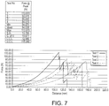
- a tear test was performed on a cut section of the gloves using a Testometric M250-3CT testing machine.
- This machine comprises upper and lower jaws for clamping material between them. The jaws are moved apart from each other and the force required to break and tear the sample is measured.
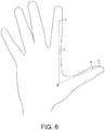
- a section was cut from each glove along the line C to E and along the line E to D as shown in the Figure such that the section contains part of the index finger, part of the thumb and the thumb crotch of the glove.
- the sample was 10mm wide by 90mm long,
- a load cell of 300kg was used for testing.
- the force is applied, by the testing machine, to the specimen at a constant speed of 100 ⁇ 10mm/minute.
- the breaking force is recorded at the break point.
- Four samples of each of the standard glove and the glove of the invention were tested. The results for each are shown in Figs. 7 and 8 , where Fig. 7 shows the results obtained for the standard glove and Fig. 8 shows the results obtained for the glove of the invention.
- the mean force required to tear and break the specimen cut from the standard glove was measured as 94N.
- the mean force required to tear and break the specimen cut from the glove of the invention was measured as 104N, giving an increase in strength in the glove of the invention of approximately 10%.
- the higher force required to tear and break the specimen cut from the glove of the invention indicates the increased strength provided to the glove by the tuck knit ridge formed around the thumb crotch area of the glove,
Landscapes
- Engineering & Computer Science (AREA)
- Textile Engineering (AREA)
- Gloves (AREA)
Applications Claiming Priority (1)
| Application Number | Priority Date | Filing Date | Title |
|---|---|---|---|
| GBGB1815681.0A GB201815681D0 (en) | 2018-09-26 | 2018-09-26 | Knitted gloves and methods of making them |
Publications (2)
| Publication Number | Publication Date |
|---|---|
| EP3628762A2 true EP3628762A2 (de) | 2020-04-01 |
| EP3628762A3 EP3628762A3 (de) | 2020-05-06 |
Family
ID=64024343
Family Applications (1)
| Application Number | Title | Priority Date | Filing Date |
|---|---|---|---|
| EP19195222.5A Withdrawn EP3628762A3 (de) | 2018-09-26 | 2019-09-03 | Gestrickte handschuhe und verfahren zur herstellung davon |
Country Status (3)
| Country | Link |
|---|---|
| US (1) | US20200095711A1 (de) |
| EP (1) | EP3628762A3 (de) |
| GB (1) | GB201815681D0 (de) |
Citations (7)
| Publication number | Priority date | Publication date | Assignee | Title |
|---|---|---|---|---|
| US5398527A (en) | 1992-10-22 | 1995-03-21 | Shima Seiki Mfg., Ltd. | Flat knitting machine having a transferring mechanism |
| US5992183A (en) | 1997-08-08 | 1999-11-30 | Shima Seiki Manufacturing, Ltd. | Flat knitting machine |
| US6962064B1 (en) | 2004-07-16 | 2005-11-08 | Ansell Healthcare Products Llc | Knitted glove |
| US7089600B2 (en) | 2003-03-25 | 2006-08-15 | Showa Co. | Work glove |
| US7555921B2 (en) | 2004-07-16 | 2009-07-07 | Ansell Healthcare Products Llc | Knitted glove with controlled stitch stretch capability and enhanced cuff |
| US7908891B2 (en) | 2004-07-16 | 2011-03-22 | Ansell Healthcare Products Llc | Knitted glove |
| US9456645B2 (en) | 2011-04-29 | 2016-10-04 | Ansell Healthcare Products Llc | Abrasion resistant glove |
Family Cites Families (4)
| Publication number | Priority date | Publication date | Assignee | Title |
|---|---|---|---|---|
| GB142455A (en) * | 1919-04-30 | 1921-06-23 | Hemphill Co | Improvements in or relating to knitted gloves and to a method of making the same |
| US5689976A (en) * | 1996-10-24 | 1997-11-25 | Ansell Edmont Industrial, Inc. | Reinforced glove and method for forming the same |
| JP2008007900A (ja) * | 2006-06-30 | 2008-01-17 | Matsui Tebukuro Seisakusho:Kk | 部分補強編み手袋とその製造方法 |
| JP2015071837A (ja) * | 2013-10-01 | 2015-04-16 | ミドリ安全株式会社 | 補強編み袋、補強編み手袋及び袋編機 |
-
2018
- 2018-09-26 GB GBGB1815681.0A patent/GB201815681D0/en not_active Ceased
-
2019
- 2019-09-03 EP EP19195222.5A patent/EP3628762A3/de not_active Withdrawn
- 2019-09-17 US US16/572,726 patent/US20200095711A1/en not_active Abandoned
Patent Citations (8)
| Publication number | Priority date | Publication date | Assignee | Title |
|---|---|---|---|---|
| US5398527A (en) | 1992-10-22 | 1995-03-21 | Shima Seiki Mfg., Ltd. | Flat knitting machine having a transferring mechanism |
| US5992183A (en) | 1997-08-08 | 1999-11-30 | Shima Seiki Manufacturing, Ltd. | Flat knitting machine |
| US7089600B2 (en) | 2003-03-25 | 2006-08-15 | Showa Co. | Work glove |
| US6962064B1 (en) | 2004-07-16 | 2005-11-08 | Ansell Healthcare Products Llc | Knitted glove |
| US7213419B2 (en) | 2004-07-16 | 2007-05-08 | Ansell Healthcare Products Llc | Knitted glove with controlled stitch stretch capability |
| US7555921B2 (en) | 2004-07-16 | 2009-07-07 | Ansell Healthcare Products Llc | Knitted glove with controlled stitch stretch capability and enhanced cuff |
| US7908891B2 (en) | 2004-07-16 | 2011-03-22 | Ansell Healthcare Products Llc | Knitted glove |
| US9456645B2 (en) | 2011-04-29 | 2016-10-04 | Ansell Healthcare Products Llc | Abrasion resistant glove |
Also Published As
| Publication number | Publication date |
|---|---|
| US20200095711A1 (en) | 2020-03-26 |
| EP3628762A3 (de) | 2020-05-06 |
| GB201815681D0 (en) | 2018-11-07 |
Similar Documents
| Publication | Publication Date | Title |
|---|---|---|
| US7434422B2 (en) | Selective multiple yarn reinforcement of a knitted glove with controlled stitch stretch capability | |
| EP2287376B1 (de) | Gestrickter handschuh mit eingestellter maschendehnungsfähigkeit | |
| US7555921B2 (en) | Knitted glove with controlled stitch stretch capability and enhanced cuff | |
| CN1232194C (zh) | 针织手套 | |
| US20140157832A1 (en) | Multifunctional knitted glove | |
| JPH09256247A (ja) | 輪 針 | |
| EP1882763B1 (de) | Verfahren zur herstellung einer schlauchförmigen maschenware | |
| JP2013533396A (ja) | 保護手袋 | |
| EP2048270B1 (de) | Strickverfahren für Handschuhe | |
| US20110209505A1 (en) | Knitted glove with modified variable plating having a reinforced region | |
| US20200095711A1 (en) | Knitted gloves and methods of making them | |
| WO2013156790A1 (en) | Knitted glove | |
| KR20100066367A (ko) | 횡편기 및 통 모양 편성부를 구비하는 편성포 | |
| US2318772A (en) | Knitted glove | |
| JP4856648B2 (ja) | 筒状編地およびその編成方法 | |
| JP3235671U (ja) | 筒状のパイル編地 | |
| JP3232757U (ja) | マスク耳掛けバンド | |
| JP3152931U (ja) | 作業手袋 | |
| JPS6120668B2 (de) |
Legal Events
| Date | Code | Title | Description |
|---|---|---|---|
| PUAI | Public reference made under article 153(3) epc to a published international application that has entered the european phase |
Free format text: ORIGINAL CODE: 0009012 |
|
| STAA | Information on the status of an ep patent application or granted ep patent |
Free format text: STATUS: THE APPLICATION HAS BEEN PUBLISHED |
|
| AK | Designated contracting states |
Kind code of ref document: A2 Designated state(s): AL AT BE BG CH CY CZ DE DK EE ES FI FR GB GR HR HU IE IS IT LI LT LU LV MC MK MT NL NO PL PT RO RS SE SI SK SM TR |
|
| AX | Request for extension of the european patent |
Extension state: BA ME |
|
| PUAL | Search report despatched |
Free format text: ORIGINAL CODE: 0009013 |
|
| AK | Designated contracting states |
Kind code of ref document: A3 Designated state(s): AL AT BE BG CH CY CZ DE DK EE ES FI FR GB GR HR HU IE IS IT LI LT LU LV MC MK MT NL NO PL PT RO RS SE SI SK SM TR |
|
| AX | Request for extension of the european patent |
Extension state: BA ME |
|
| RIC1 | Information provided on ipc code assigned before grant |
Ipc: A41D 19/015 20060101ALI20200328BHEP Ipc: D04B 15/74 20060101ALI20200328BHEP Ipc: D04B 7/34 20060101AFI20200328BHEP Ipc: D04B 1/28 20060101ALI20200328BHEP |
|
| 18D | Application deemed to be withdrawn |
Effective date: 20201107 |