EP3628771B1 - Dispositif de repassage de linge - Google Patents
Dispositif de repassage de linge Download PDFInfo
- Publication number
- EP3628771B1 EP3628771B1 EP19198552.2A EP19198552A EP3628771B1 EP 3628771 B1 EP3628771 B1 EP 3628771B1 EP 19198552 A EP19198552 A EP 19198552A EP 3628771 B1 EP3628771 B1 EP 3628771B1
- Authority
- EP
- European Patent Office
- Prior art keywords
- ironer
- base layer
- links
- layer
- strands
- Prior art date
- Legal status (The legal status is an assumption and is not a legal conclusion. Google has not performed a legal analysis and makes no representation as to the accuracy of the status listed.)
- Active
Links
Images

Classifications
-
- D—TEXTILES; PAPER
- D06—TREATMENT OF TEXTILES OR THE LIKE; LAUNDERING; FLEXIBLE MATERIALS NOT OTHERWISE PROVIDED FOR
- D06F—LAUNDERING, DRYING, IRONING, PRESSING OR FOLDING TEXTILE ARTICLES
- D06F83/00—Coverings or pads for ironing or pressing members
-
- D—TEXTILES; PAPER
- D06—TREATMENT OF TEXTILES OR THE LIKE; LAUNDERING; FLEXIBLE MATERIALS NOT OTHERWISE PROVIDED FOR
- D06F—LAUNDERING, DRYING, IRONING, PRESSING OR FOLDING TEXTILE ARTICLES
- D06F65/00—Ironing machines with rollers rotating against curved surfaces
- D06F65/02—Ironing machines with rollers rotating against curved surfaces with one roller only
-
- D—TEXTILES; PAPER
- D06—TREATMENT OF TEXTILES OR THE LIKE; LAUNDERING; FLEXIBLE MATERIALS NOT OTHERWISE PROVIDED FOR
- D06F—LAUNDERING, DRYING, IRONING, PRESSING OR FOLDING TEXTILE ARTICLES
- D06F67/00—Details of ironing machines provided for in groups D06F61/00, D06F63/00, or D06F65/00
- D06F67/02—Rollers; Heating arrangements therefor
Definitions
- the invention relates to a device for ironing items of laundry according to the preamble of claim 1 and a further device for ironing items of laundry according to the preamble of claim 2.
- Laundry items are smoothed by ironing and finally dried.
- the ironing takes place mainly in commercial laundries with devices of various designs.
- the invention relates to devices that are designed as a bowl mangle or a lack of ribbons.
- Trough ironers have one or more successive cylindrical ironer rollers which can be driven in rotation and one ironer trough fixedly assigned to the or each ironer roller.
- the respective ironer trough is preferably designed to be elastic in order to be able to adapt flexibly to the respective ironer roller.
- Ribbon ironers have at least one ironer body that can be driven in a stationary or rotating manner.
- Rotary drivable ironer bodies are also cylindrical in the case of band ironers.
- the standing ironer bodies can have any other cross-section in the case of band ironers.
- the single ironer or all of the ironers of the lack of ligaments is assigned at least one circumferentially drivable ironer belt.
- the ironer belt is used to transport the laundry items to be deficient along the ironer body or around the respective ironer body. In addition, the ironer belt presses the laundry items to be deficient against the respective ironer body.
- a winding of a mangle roller for a flat ironer known, which is made of felt.
- Interlinked springs made of metallic material are provided between the felt wrapping and the cylindrical outer surface of the ironer roller. These form a spring base for the winding.
- a winding for a mangle roller is known.
- This wrapping is designed in two layers in that it has an upper layer and a lower layer. Both layers are made of a fleece with a textile base or mesh fabric made of warp and weft threads embedded therein.
- the invention is based on the object of creating devices for ironing items of laundry, the wrapping or ironing band of which has improved stability.
- a device for solving this problem has the features of claim 1. Accordingly, it is provided that the wrapping of the at least one ironer roller has a base layer of interconnected, preferably chained, or connected links and at least one nonwoven layer connected to the base layer.
- Another device for independently solving the above-mentioned object has the features of claim 2.
- This device is characterized by a mangle band which has a base layer made up of interlinked or connected links and at least one fleece layer connected to the base layer.
- the wrapping or the ironer tape has a base layer with several connected links and at least one fleece layer connected to the base layer.
- a base layer By forming the base layer from connected or interlinked links, a three-dimensional reinforcement of the nonwoven layer connected to the base layer is achieved.
- the base layer is extremely flexible, so it can cling to the ironer roller or the ironer body continuously and without any gaps.
- this In the case of the ironer belt, there is also the fact that this also serves as a conveyor belt and, in particular, has to be deflected around smaller radii. Due to its formation of interconnected, in particular interlinked, links, the base layer has a relatively high dimensional stability with good flexibility at the same time.
- the ironer winding or the ironer band having at least one such base layer change their shape significantly less than conventional windings of ironer rollers or ironer bands.
- the wraps or ironer bands according to the invention therefore have a longer service life and do not need to be replaced as often.
- the links are linked to one another by elongate, rod-like connectors.
- the connectors extend transversely to the direction of rotation of the winding or the transport direction of the ironer tape.
- the links of the base layer are formed from adjacent strands running in the direction of rotation of the winding or running direction of the ironer strip, which are preferably braided around alternately one or the other side of transversely directed rod-like bars.
- Such links do not need to be linked separately. They are directly linked to one another due to their formation from adjacent strands running continuously and / or interrupted in the longitudinal direction of the winding or the ironer band.
- the transversely directed rods have a further function; they not only subdivide the links functionally formed between adjacent rods, but also serve to give the longitudinally extending adjacent or juxtaposed strands a flat zigzag shape. This creates a three-dimensional mesh from the strands with the bars running transversely at preferably 90 °, which also forms a base layer of a certain thickness, the thickness of the base layer depending on the diameter of the bars.
- Both devices or mangles with a winding or a mangle band which have a base layer of connected links and a nonwoven layer connected to the base layer, can have a width of over 5 m due to this structure of the winding or the ironer band.
- the rod-like connectors run at right angles to the direction of rotation of the winding or the transport direction of the ironer strip. With this arrangement, the rod-like connectors do not experience any deformation when the base layer is curved or its curvature is changed in the direction of rotation of the winding or transport direction of the ironer tape, for example by deflections.
- the respective base layer preferably has a multiplicity of links, preferably of identical design, which are arranged relative to one another for the comb-like engagement of end regions of adjacent links. As a result of this comb-like engagement of adjacent links, the links can be simply linked to one another to form the base layer.
- a preferred embodiment of the base layer provides that the links are articulated to one another at points where they intermesh in a comb-like manner. Such articulated connections between the adjacent links lead to a particularly flexible and thus adaptable base layer.
- the links also allow a simple and permanent connection between the base layer and the at least one nonwoven layer.
- This winding is preferably carried out in the manner of a helical spring, the longitudinal direction of which runs transversely, preferably at a right angle, to the direction of rotation of the winding or the direction of travel of the ironer strip.
- Such links can be formed inexpensively and give the base layer a high level of stability. Above all, the shape of the links can influence the thickness and thus the stability of the base layer. In this way, many links in a row of any size and shape can be produced simultaneously in one operation and a base layer with the desired thickness and stability can be formed from them.
- the links can have an oval-like shape as seen in the longitudinal direction of their joint axis. Such links spatially span a three-dimensional space, free space or interior. Provision can be made for this intermediate space, free space or interior space to be completely or partially filled by at least one filler body. At least one filler body can be assigned to each link, but also only to a few selected links, for example every second of the successive links.
- the filling bodies are preferably formed from a dimensionally stable material. They can be elastic, in particular elastically flexible. It is conceivable to make the packing air-permeable and / or electrically conductive. The filling bodies make it possible to stabilize the base layer and to create better air permeability of the base layer. In addition, the filling bodies can contribute to the base layer becoming electrically conductive and thereby avoiding or at least reducing electrostatic charges in the missing laundry.
- the nonwoven layer extends into the base layer.
- the respective fleece layer can also extend through the entire base layer. If a fleece layer is assigned to both sides of the base layer, the respective fleece layer is preferably only connected to that side of the base layer to which the fleece layer is assigned. However, it is also conceivable that on both sides of the base layer assigned nonwoven layers when they are connected to the base layer, each nonwoven layer extends through the base layer. Then the two opposite sides of the nonwoven layers assigned to the base layer overlap in the area of the base layer.
- the single fleece layer on one side of the base layer or both fleece layers on each side of the base layer are connected by needling, tufting, sewing or the like. These connection techniques can be quickly performed by machine and lead to an intimate connection with the base layer.
- a nonwoven layer arranged on both sides of the base layer there is also the possibility that the two opposing nonwoven layers may also be connected to one another in the area of the intermediate base layer by needling, tufting, sewing or the like.
- the base layer in particular its links, strands, rods and / or connectors, are formed from plastic. This increases the flexibility of the winding or the ironer band. In addition, plastic is resistant to the Most of the moisture to be removed from the laundry when ironing and not susceptible to corrosion.
- the base layer is formed or made endless.
- the base layer formed from connected and / or interconnected links creates ideal conditions for this. Above all, this creates seamless or seamless, closed ironer bands or ironer wraps. Such shortage tapes or wraps do not leave any impressions or other quality-reducing impairments on the missing items of laundry.
- the device shown relates to a bowl ironer 10.
- the bowl ironer 10 has a cylindrical ironer roller 11 which can be driven to rotate about a preferably horizontal longitudinal center axis 12. This longitudinal center axis 12 also forms the axis of rotation of the ironer roller 10.
- the ironer roller 11 is provided with a winding 13.
- the wrapping 13 is arranged on the outside around a cylindrical outer surface 14 of the ironer roller 11, specifically in such a way that the wrapping 13 completely covers the cylindrical outer surface 14 and / or surrounds it seamlessly. Between the outer surface 14, the ironer roller 11 and the winding 13 can be arranged a spiral base wound around the lateral surface 14.
- the ironer roller 11 is assigned a preferably flexible ironer trough 15.
- the ironer trough 15 approximately surrounds the lower half of the ironer roller 11, so that the ironer trough 15 is semicircular in cross section.
- the ironer trough 15 can be heated. For this purpose, it has flow channels in the interior for a heating medium, for example steam or thermal oil.
- the ironer trough 15 is mounted on opposite longitudinal edges 16 and 17 on a fixed frame 18 of the ironer 10.
- a (right) longitudinal edge 15, seen in the direction of rotation 19 of the ironer roller 11, on an inlet side 20 of the hollow ironer 10 is firmly connected to the frame 18.
- On the opposite (left) longitudinal edge 17 of the ironer trough is an outlet side 21 of the ironer 10.
- the longitudinal edge 17 of the ironer trough 15 is movably supported on the frame 18 on the outlet side 21 by means of a slightly inclined pendulum support 22.
- the invention is not limited to the bowl ironer 10 described above. Rather, it can also be used for flat ironers 10 of a different design, for example those without a pendulum support 22 and also those that have a rigid ironer bowl 15.
- the invention is not only suitable for those in the Fig. 1 Trough ironer 10 shown with only a single ironer roller 11 and only one ironer trough associated with it 15.
- the invention is particularly suitable for ironers 10 with several successive ironer rollers 11 of the same or different size and design and one ironer trough 15 associated with each ironer roller 11 Mangle troughs 15 of successive ironer rollers 11 connected by a bridge.
- This bridge is used to transfer the items of laundry to be deficient, not shown in the figures, from the ironer gap 23 between the outside of the winding 13 of the ironer roller 11 and a smooth flattening surface 24 of the stationary, stationary ironer trough 15, which is directed towards the ironer roller 11.
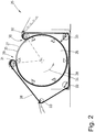
- the Fig. 2 shows a device designed as a lack of ligaments 25.
- the ribbon ironer 25 has a stationary, stationary and cylindrical ironer body 26.
- the ironer 25 has a ironer belt 28 which largely surrounds a cylindrical outer surface 27 of the ironer body 26.
- the endless ironer belt 28 is continuously revolving in the manner of a Conveyor belt drivable, it slides along the majority of the lateral surface 27 of the stationary ironer body 26.
- the ironer body 26 of the ligament ironer 25 can be heated. This heating is preferably carried out from the inside of the ironer body 26.
- the ironing body 26 can be heated with any heat transfer medium.
- the ironer band 28 is brought up to the ironer body 26 on an inlet side 29 above the ironer body 26 and is diverted from the ironer body 26 in the area of an outlet side 30 near the inlet side 29.
- the ironer belt 28 is driven in the transport direction or the direction of rotation 34.
- the ironer belt 28 is guided on the inlet side 29 and the outlet side 30 by guide drums 31 and 32 running parallel to each other and to the longitudinal center axis 12 of the ironer body 26 up to the guide drum 32 on the outlet side 30. From the guide drum 32 on the outlet side 30, the ironer belt 28 is returned as a return run to the guide drum 31 on the inlet side 29.
- the return run of the ironer belt 28 is at a distance from the ironer body 26 and guided around the ironer body 26 around the correspondingly arranged deflecting drums 33.At least one of the deflecting drums 31, 32 or 33 can be driven in rotation to drive the ironer belt 28 in the direction of rotation 34.
- FIG. 2 An Indian Fig. 2
- the ironer gap (not shown) for the laundry items to run through the ironer 25 is formed between the ironer body 26 and the part of the ironer belt 28 wrapping around it from the inlet side 29 to the outlet side 30.
- the circumferential area of the lateral surface 27 of the stationary ironer body 26 wrapped around by the ironer band 28 forms a stationary flattening surface 35 Fig. 2
- the ribbon ironer 25 described above only has a single stationary ironer body 26. Ribbon ironers 25 are also conceivable which have several successive, identical or different ironer bodies 26. The laundry items are then removed from the single ironer belt 28 or also from separate ironer belts 28 one after the other along such a belt ironer 25 having a plurality of ironer bodies 26.
- the invention is also not limited to ribbon mangles 25, which are described in the above and in the Fig. 2 manner shown are formed.
- the invention is also suitable for any differently designed ironer belts 25, in particular those in which the or each cylindrical ironer body 26 is driven together with the ironer belt 28, but the drive speed is selected so that there is slippage between the ironer belt 28 and the flattening surface 35 of the mangle body 26 arises.
- the ironer body 26 is not cylindrical, but rather has a different cross-section, for example an elliptical or oval cross-section.
- the Figures 3 to 6 show various exemplary embodiments of the design of the ironer belt 28, the ironer belt 25 and the winding 13 of the ironer roller 11.
- the following explains the design using the example of the ironer belt 28:
- the ironer band 28 has a base layer and at least on one side thereof a fleece layer.
- the base layer and the fleece layer are connected to one another. This connection can be made by needles, tufting, linking, sewing or the like.
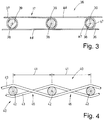
- the Fig. 3 shows a longitudinal section through a short section of a first embodiment of a base layer 36.
- This base layer 36 is formed from a plurality of individual, separate links 37 which are linked together to form the base layer 36.
- This linking of the individual links 37 also means that the base layer 36 is endless made.
- all of the links 37 are of the same design, namely approximately oval and have the same dimensions.
- a plurality of links 37 are arranged at a parallel spacing transversely to the direction of rotation 34 of the ironer belt 28 in a row running transversely to the direction of rotation 34 of the ironer belt 28.
- Several such chained rows follow one another in the direction of rotation 34 of the ironer belt 28.
- the distances between adjacent links 37 in the same row are approximately the same as the width of the links.
- the links 37 of adjacent rows are each arranged offset from one another (with a gap) by the width of one link.
- the links 37 of adjacent rows can intermesh in a comb-like manner with their end regions facing one another.
- the one into the other Engaging end regions of adjacent links 37, in particular adjacent rows of adjacent links 37 thus each form a joint axis 38.
- the links 37 are each formed from a revolving, endless strand 47.
- the strand 47 of each link 37 has an approximately oval shape.
- the strands 47 of each base ply 36 have spaced apart sections 48 that run parallel to one another. When the base ply 36 is straight, the sections 48 run in a straight line. With a curved base layer 36, the sections 48 of the strands 47 have a correspondingly curved course.
- the links 37 of adjacent rows are connected in the base layer 36 in the area of each hinge axis 38 by a rod-like or rod-like connector 39.
- this has a cylindrical cross-section, but can also have a non-circular, for example lens-like, cross-section.
- the connectors 39 also extend transversely to the direction of rotation 34 of the ironer belt 28.
- the base layer 36 of each connector 39 has hinge-like connections of the links 37 and thus a very high and almost unlimited flexibility .
- the base layer 36 of the ironer belt 28 does not interfere with the deflection at the deflection drums 31, 32 and 33, even if these only have a very small diameter.
- the hinge axes 39 for connecting the individual rows of the links 37 of the base layer 36 thus lead in the direction of rotation 34 to unlimited flexibility of the ironer band 28.
- the rod-like connectors 39 can be formed from a material which gives the connector 39 a high degree of stability. Then the base layer 36 is only slightly flexible transversely to the direction of rotation 34 of the ironer band 28. Should such flexibility transversely to the direction of rotation 34 not be necessary or not desired, the connectors 39 can be formed from easily bendable rods or even tubes.
- Base layer 36 shown in sections has a certain thickness or strength depending on the height of the links 37 and the diameter of the connector 39. This gives the base layer 36 a three-dimensional structure. This structure gives the base layer 36 the desired dimensional stability in spite of its flexibility at least in the direction of rotation 34 of the ironer belt 28. This dimensional stability is characterized in that the base layer 36 is or remains flexible due to the many individual interconnected links 37, but maintains its shape over the long term.
- the base layer 36 has between the sections 48 of the strands 47 of the links 37 and between the rod-like or rod-like connectors 39 a three-dimensional free, inner or intermediate space, which differs from that in the Fig. 3
- the base layer 36 shown can be completely or partially filled by one or more fillers.
- the filling bodies can be rigid or flexible or elastic.
- the filler bodies can optionally also be perforated and / or porous so that they are at least air-permeable.
- the fillers ensure that the spaced apart portions 48 of the strand 47 of each link 37 maintain their spacing. This makes the base layer 36 more permeable to air, in particular when the filler bodies are also porous or perforated. It is conceivable that the filling bodies are formed from an electrically conductive material. Such fillers make the base layer 36 electrically conductive in order to avoid or eliminate electromagnetic charging of the base layer 36 or the wrapping 13 or the ironer band 28.
- the filling bodies can be secured against displacement and / or slipping in the free space between the sections 48 and the connectors 39, in particular by being wholly or partially connected to the sections 48 of the strands 47, for example by gluing.
- the sections of the base layer 40 defined as links 41 extend between two elongated rods 42, which extend transversely to the direction of rotation 34 of the ironer band 28 like the connectors 39 of the base layer 36 and which also act as hinge axes.
- a respective link 41 of the base ply 40 is formed by a section of the base ply 40 extending between two adjacent, parallel rods 42.
- the strands 43 extending continuously in the direction of rotation 34 of the ironer band 28 and lying next to one another in the transverse direction of the ironer band 28 are around the
- the respective rod 42 is laid around in a Z-shape, so that the respective strand 43 is led around on one side of a first rod 42 and on another side of the next following rod 42.
- Adjacent strands 43 are led around the respective rod 42 alternately once at the top and once at the bottom. In this way, in the transverse direction of the ironer belt 28, a strand guided around the respective rod 42 at the top and one at the bottom always alternates. Between successive bars 42, adjacent strands 43 running parallel to one another cross at intersection points. As a result, the strands 43 together with the rods 42 form a braided structure of the base layer 40.
- the base layers 36 and 40 can in principle be designed for the wrapping 13 of the flat ironer 10 in the same way as in the case of the ironer band 28.
- the connectors 39 and the rods 42 are provided with the same diameters and the spacings between the connectors 39 and rods 42 are the same.
- the diameters of the rods 42 and the distances between them in the base layer 40 from the distances between the connectors 39 and the diameters of the same in the base layer 36 differ from one another.
- the distances between the rods 42 in the base layer 40 can be smaller than in the base layer 36.
- Both the base layer 36 and the base layer 40 are preferably formed from plastic, in particular a thermoplastic plastic. It is also conceivable to form the base layers 36 and / or 40 entirely or partially from a different material, for example stainless steel, in particular steel wire.
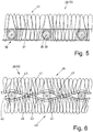
- the Figures 5 and 6 each show a complete section of the ironer belt 28, namely the Fig. 5 with the base layer 36 and the Fig. 6 with the base position 40.
- the base layer 36 is connected to a single fleece layer 44.
- the thickness of the part of the fleece layer 44 protruding on one side opposite the base layer 36 is somewhat greater than the thickness of the base layer 36. It is also conceivable that the part of the fleece layer 44 protruding on one side with respect to the base layer 36 is just as thick as the base layer 36 or even somewhat thinner.
- a part of the fleece layer 44 extends through the entire base layer 36 in order to connect the same to the base layer 36.
- the fleece layer 44 is only connected to that side of the base layer 36 to which the fleece layer 44 is assigned.
- the fleece layer 44 is then thinner and does not extend through the entire base layer 36, preferably only through or around the upper sections of the links 37.
- the embodiment of the Fig. 6 shows a section of the complete ironer band 28, which has a fleece layer 45 on each side of the base layer 40.
- the areas of the fleece layers 45 protruding opposite both sides of the base layer 40 are of the same size in the exemplary embodiment shown, in particular of the same thickness. It is also conceivable that the fleece layer 45 is thinner on one side than the fleece layer 45 on the other side of the base layer 40.
- the subregions of the nonwoven layers 45 protruding beyond the base layer 40 have a thickness which corresponds approximately to the thickness of the base layer 40.
- the thicknesses of the part of the nonwoven layers 45 protruding from the base layer 40 being smaller or greater than the thickness of the base layers.
- the upper fleece layer 45 is connected to sections of the adjacent strands 43 lying above a plane which runs through the longitudinal center axes of the strands 43.
- the lower fleece layer 45 is only connected to the sections of the successive strands 43 lying below the aforementioned plane through the rods 42.
- the fleece layers 45 overlap at the crossing points 46 of the adjacent strands 43, so that the fleece layers 45 are also connected to one another here.
- both fleece layers 45 are connected to all of the strands 43, in particular adjacent strands 43.
- both fleece layers 45 extend through the entire base layer 40 and overlap each other in the entire area of the base layer 40. This leads to a particularly intensive connection of the fleece layers 45 to the base layer 40 and of the fleece layer 45 to one another.
- the base layer 36 with a fleece layer 45 on both sides, the connection of the fleece layers 45 to the base layer 36 analogously to the exemplary embodiment the Fig. 5 can be done.
- the base layer 40 with only a single, one-sided nonwoven layer 44, namely according to the one in FIG Fig. 5 shown way.
- connection of the fleece layers 40 in the embodiment of FIG Fig. 5 and the connections of the fleece layers 45 in the embodiment of FIG Fig. 6 with the base layer 40 is done by needling, tufting, linking, sewing or the like.
- the fleece layers 44 and 45 are preferably formed from a felt fleece, in particular a needle fleece.
- the wrapping 13 of the bowl ironer 10 can also be formed.
Landscapes
- Engineering & Computer Science (AREA)
- Textile Engineering (AREA)
- Treatment Of Fiber Materials (AREA)
Claims (10)
- Dispositif de repassage d'articles de lingerie, ledit dispositif comprenant au moins un rouleau de repassage (11) pouvant être entraîné en rotation et une cuvette de repassage (15) associée au rouleau de repassage (11), une surface latérale (14) du rouleau de repassage (11) étant pourvue d'un enrubannage extérieur (13) qui comporte une couche de base (36 ; 40) et au moins une couche de non-tissé (44 ; 45) reliée à la couche de base (36 ; 40), caractérisé en ce que la couche de base (36 ; 40) de l'enrubannage (13) comporte des éléments contigus ou interconnectés (37 ; 41), et les éléments (37) sont interconnectés par le biais de connecteurs allongés (39) en forme de tige qui s'étendent transversalement au sens de rotation (19) de l'enrubannage (13) ou les éléments (41) sont formés à partir de brins adjacents (43) qui s'étendent dans le sens de rotation (19) du rouleau de repassage (11), les brins adjacents (43) étant tressés en alternance sur d'autres côtés de barres (42) qui s'étendent transversalement au sens de rotation (19).
- Dispositif de repassage d'articles de lingerie, ledit dispositif comprenant au moins un corps de repassage (26) et au moins une courroie de repassage (28) qui est associée à l'au moins un corps de repassage (26) et qui peut être entraînée en rotation, caractérisé en ce que la bande de repassage (28) comporte une couche de base (36 ; 40) formée d'éléments contigus ou interconnectés (37 ; 41) et au moins une couche de non-tissé (44 ; 45) reliée à la couche de base (36 ; 40), et les éléments (37) sont interconnectés par le biais de connecteurs allongés (39) en forme de tige qui s'étendent transversalement au sens de rotation (34) de la bande de repassage (28) ou les éléments (41) sont formés à partir de brins adjacents (43) qui s'étendent dans le sens de rotation (34) de la bande de repassage (28), les brins adjacents (43) étant tressés en alternance sur d'autres côtés de barres (42) qui s'étendent transversalement au sens de rotation (34).
- Dispositif selon la revendication 1 ou 2, caractérisé en ce que la couche de base (36) comporte une multitude d'éléments identiques (37) qui sont disposés les uns par rapport aux autres de façon à former un engagement en forme de peigne de régions d'extrémité d'éléments adjacents et/ou successifs (37).
- Dispositif selon la revendication 3, caractérisé en ce que les éléments (37) sont reliés de manière articulée les uns aux autres en des emplacements où ils s'engagent les uns dans les autres à la manière d'un peigne.
- Dispositif selon l'une des revendications 1 à 4, caractérisé en ce que les éléments (37) sont formés de brins (47) enroulés en hélice ou en spirale.
- Dispositif selon la revendication 5, caractérisé en ce que les brins (47) des éléments enroulés (37) s'étendent à la manière d'un ovale lorsque l'on observe dans la direction longitudinale de leurs axes d'articulation (38) et entourent un espace intermédiaire ou espace libre dans lequel est disposé au moins un corps de remplissage qui remplit au moins partiellement l'espace intermédiaire ou l'espace libre.
- Dispositif selon l'une des revendications précédentes, caractérisé en ce que la liaison de l'unique ou de chaque couche de non-tissé (44 ; 45) avec la couche de base (36 ; 40) s'étend jusque dans la couche de base (36 ; 40) et/ou à travers la couche de base (36 ; 40).
- Dispositif selon l'une des revendications précédentes, caractérisé en ce que la couche de non-tissé (44) est reliée à un côté de la couche de base (36 ; 40) ou les deux couches de non-tissé (45) sont reliées aux deux côtés de la couche de base (36 ; 40) par aiguilletage, remaillage, tuftage, couture ou similaire.
- Dispositif selon l'une des revendications précédentes, caractérisé en ce que la couche de base (36 ; 40), notamment ses éléments (37 ; 41), connecteurs (39), tiges (42) et/ou brins (43), sont en matière synthétique.
- Dispositif selon l'une des revendications précédentes, caractérisé en ce que la couche de base (36 ; 40) est formée sans fin ou est rendue sans fin.
Applications Claiming Priority (2)
| Application Number | Priority Date | Filing Date | Title |
|---|---|---|---|
| DE102018007680 | 2018-09-28 | ||
| DE102018008406.0A DE102018008406A1 (de) | 2018-09-28 | 2018-10-25 | Vorrichtung zum Mangeln von Wäschestücken |
Publications (2)
| Publication Number | Publication Date |
|---|---|
| EP3628771A1 EP3628771A1 (fr) | 2020-04-01 |
| EP3628771B1 true EP3628771B1 (fr) | 2021-07-14 |
Family
ID=67998265
Family Applications (1)
| Application Number | Title | Priority Date | Filing Date |
|---|---|---|---|
| EP19198552.2A Active EP3628771B1 (fr) | 2018-09-28 | 2019-09-20 | Dispositif de repassage de linge |
Country Status (1)
| Country | Link |
|---|---|
| EP (1) | EP3628771B1 (fr) |
Family Cites Families (3)
| Publication number | Priority date | Publication date | Assignee | Title |
|---|---|---|---|---|
| GB392097A (en) * | 1931-11-23 | 1933-05-11 | Scheibe Paul | Improvements in or relating to mangle rollers |
| US2146670A (en) * | 1935-10-11 | 1939-02-07 | Atlas Powder Co | Tapered padding for laundry rolls |
| DE8807426U1 (de) * | 1988-06-07 | 1988-10-27 | Elasto-Press Schmitz GmbH, 3250 Hameln | Mangelwalze mit Textilauflage |
-
2019
- 2019-09-20 EP EP19198552.2A patent/EP3628771B1/fr active Active
Also Published As
| Publication number | Publication date |
|---|---|
| EP3628771A1 (fr) | 2020-04-01 |
Similar Documents
| Publication | Publication Date | Title |
|---|---|---|
| DE2540490B2 (de) | Sieb für Papiermaschinen | |
| DE3024713A1 (de) | Strukturteil fuer schlafsaecke | |
| DE19923088C1 (de) | Papiermaschinenbespannung, insbesondere als Trockensieb | |
| DE2747160A1 (de) | Papiermaschinentuch | |
| DE3914533A1 (de) | Band fuer papiermaschinen | |
| DE3928485C2 (de) | Papiermaschinentuch | |
| DE4122805C1 (de) | Drahtgliederband | |
| EP0472072A1 (fr) | Bande à maillons de fil | |
| DE3735709C2 (de) | Papiermaschinenband | |
| EP2857577B1 (fr) | Dispositif de repassage de pièces de linge | |
| DE102018008406A1 (de) | Vorrichtung zum Mangeln von Wäschestücken | |
| DE3914534C1 (fr) | ||
| DE2455185A1 (de) | Gewebe zur herstellung von papier | |
| EP1452639A1 (fr) | Habillage de machine à papier | |
| EP3628771A1 (fr) | Dispositif de repassage de linge | |
| CH670217A5 (fr) | ||
| DE3027370C2 (de) | Vorrichtung zum Herstellen von Kühlrippenrohren für Wärmetauscher | |
| DE1407868C3 (de) | Taschen- oder Schlauchfilter für gasförmige Medien | |
| DE2803079C2 (de) | Vorrichtung zum mechanischen Krumpfen einer Textilbahn | |
| EP2199458B1 (fr) | Toile de formage | |
| DE2145967A1 (de) | Vorrichtung zum Abstützen von mit einer Flüssigkeit imprägnierten Bahnen | |
| EP0837184B1 (fr) | Section à séchage | |
| EP2888953A2 (fr) | Bande d'aspiration d'une machine de l'industrie de traitement du tabac | |
| WO2017077040A1 (fr) | Vêtement de sport comprenant au moins une zone de thermorégulation | |
| DE2814689C3 (de) | Bügelmaschine mit paarweise angeordneten Walzen |
Legal Events
| Date | Code | Title | Description |
|---|---|---|---|
| PUAI | Public reference made under article 153(3) epc to a published international application that has entered the european phase |
Free format text: ORIGINAL CODE: 0009012 |
|
| STAA | Information on the status of an ep patent application or granted ep patent |
Free format text: STATUS: THE APPLICATION HAS BEEN PUBLISHED |
|
| AK | Designated contracting states |
Kind code of ref document: A1 Designated state(s): AL AT BE BG CH CY CZ DE DK EE ES FI FR GB GR HR HU IE IS IT LI LT LU LV MC MK MT NL NO PL PT RO RS SE SI SK SM TR |
|
| AX | Request for extension of the european patent |
Extension state: BA ME |
|
| STAA | Information on the status of an ep patent application or granted ep patent |
Free format text: STATUS: REQUEST FOR EXAMINATION WAS MADE |
|
| 17P | Request for examination filed |
Effective date: 20200929 |
|
| RBV | Designated contracting states (corrected) |
Designated state(s): AL AT BE BG CH CY CZ DE DK EE ES FI FR GB GR HR HU IE IS IT LI LT LU LV MC MK MT NL NO PL PT RO RS SE SI SK SM TR |
|
| RIC1 | Information provided on ipc code assigned before grant |
Ipc: D06F 83/00 20060101AFI20210118BHEP Ipc: D06F 67/02 20060101ALN20210118BHEP Ipc: D06F 65/02 20060101ALN20210118BHEP |
|
| GRAP | Despatch of communication of intention to grant a patent |
Free format text: ORIGINAL CODE: EPIDOSNIGR1 |
|
| STAA | Information on the status of an ep patent application or granted ep patent |
Free format text: STATUS: GRANT OF PATENT IS INTENDED |
|
| RIC1 | Information provided on ipc code assigned before grant |
Ipc: D06F 83/00 20060101AFI20210217BHEP Ipc: D06F 67/02 20060101ALN20210217BHEP Ipc: D06F 65/02 20060101ALN20210217BHEP |
|
| INTG | Intention to grant announced |
Effective date: 20210315 |
|
| GRAS | Grant fee paid |
Free format text: ORIGINAL CODE: EPIDOSNIGR3 |
|
| GRAA | (expected) grant |
Free format text: ORIGINAL CODE: 0009210 |
|
| STAA | Information on the status of an ep patent application or granted ep patent |
Free format text: STATUS: THE PATENT HAS BEEN GRANTED |
|
| AK | Designated contracting states |
Kind code of ref document: B1 Designated state(s): AL AT BE BG CH CY CZ DE DK EE ES FI FR GB GR HR HU IE IS IT LI LT LU LV MC MK MT NL NO PL PT RO RS SE SI SK SM TR |
|
| REG | Reference to a national code |
Ref country code: GB Ref legal event code: FG4D Free format text: NOT ENGLISH |
|
| REG | Reference to a national code |
Ref country code: DE Ref legal event code: R096 Ref document number: 502019001812 Country of ref document: DE |
|
| REG | Reference to a national code |
Ref country code: IE Ref legal event code: FG4D Free format text: LANGUAGE OF EP DOCUMENT: GERMAN |
|
| REG | Reference to a national code |
Ref country code: AT Ref legal event code: REF Ref document number: 1410746 Country of ref document: AT Kind code of ref document: T Effective date: 20210815 |
|
| PGFP | Annual fee paid to national office [announced via postgrant information from national office to epo] |
Ref country code: FR Payment date: 20210826 Year of fee payment: 3 |
|
| REG | Reference to a national code |
Ref country code: LT Ref legal event code: MG9D |
|
| REG | Reference to a national code |
Ref country code: NL Ref legal event code: MP Effective date: 20210714 |
|
| PG25 | Lapsed in a contracting state [announced via postgrant information from national office to epo] |
Ref country code: HR Free format text: LAPSE BECAUSE OF FAILURE TO SUBMIT A TRANSLATION OF THE DESCRIPTION OR TO PAY THE FEE WITHIN THE PRESCRIBED TIME-LIMIT Effective date: 20210714 Ref country code: NO Free format text: LAPSE BECAUSE OF FAILURE TO SUBMIT A TRANSLATION OF THE DESCRIPTION OR TO PAY THE FEE WITHIN THE PRESCRIBED TIME-LIMIT Effective date: 20211014 Ref country code: NL Free format text: LAPSE BECAUSE OF FAILURE TO SUBMIT A TRANSLATION OF THE DESCRIPTION OR TO PAY THE FEE WITHIN THE PRESCRIBED TIME-LIMIT Effective date: 20210714 Ref country code: PT Free format text: LAPSE BECAUSE OF FAILURE TO SUBMIT A TRANSLATION OF THE DESCRIPTION OR TO PAY THE FEE WITHIN THE PRESCRIBED TIME-LIMIT Effective date: 20211115 Ref country code: LT Free format text: LAPSE BECAUSE OF FAILURE TO SUBMIT A TRANSLATION OF THE DESCRIPTION OR TO PAY THE FEE WITHIN THE PRESCRIBED TIME-LIMIT Effective date: 20210714 Ref country code: BG Free format text: LAPSE BECAUSE OF FAILURE TO SUBMIT A TRANSLATION OF THE DESCRIPTION OR TO PAY THE FEE WITHIN THE PRESCRIBED TIME-LIMIT Effective date: 20211014 Ref country code: RS Free format text: LAPSE BECAUSE OF FAILURE TO SUBMIT A TRANSLATION OF THE DESCRIPTION OR TO PAY THE FEE WITHIN THE PRESCRIBED TIME-LIMIT Effective date: 20210714 Ref country code: SE Free format text: LAPSE BECAUSE OF FAILURE TO SUBMIT A TRANSLATION OF THE DESCRIPTION OR TO PAY THE FEE WITHIN THE PRESCRIBED TIME-LIMIT Effective date: 20210714 Ref country code: FI Free format text: LAPSE BECAUSE OF FAILURE TO SUBMIT A TRANSLATION OF THE DESCRIPTION OR TO PAY THE FEE WITHIN THE PRESCRIBED TIME-LIMIT Effective date: 20210714 Ref country code: ES Free format text: LAPSE BECAUSE OF FAILURE TO SUBMIT A TRANSLATION OF THE DESCRIPTION OR TO PAY THE FEE WITHIN THE PRESCRIBED TIME-LIMIT Effective date: 20210714 |
|
| PG25 | Lapsed in a contracting state [announced via postgrant information from national office to epo] |
Ref country code: PL Free format text: LAPSE BECAUSE OF FAILURE TO SUBMIT A TRANSLATION OF THE DESCRIPTION OR TO PAY THE FEE WITHIN THE PRESCRIBED TIME-LIMIT Effective date: 20210714 Ref country code: LV Free format text: LAPSE BECAUSE OF FAILURE TO SUBMIT A TRANSLATION OF THE DESCRIPTION OR TO PAY THE FEE WITHIN THE PRESCRIBED TIME-LIMIT Effective date: 20210714 Ref country code: GR Free format text: LAPSE BECAUSE OF FAILURE TO SUBMIT A TRANSLATION OF THE DESCRIPTION OR TO PAY THE FEE WITHIN THE PRESCRIBED TIME-LIMIT Effective date: 20211015 |
|
| REG | Reference to a national code |
Ref country code: DE Ref legal event code: R119 Ref document number: 502019001812 Country of ref document: DE |
|
| PG25 | Lapsed in a contracting state [announced via postgrant information from national office to epo] |
Ref country code: DK Free format text: LAPSE BECAUSE OF FAILURE TO SUBMIT A TRANSLATION OF THE DESCRIPTION OR TO PAY THE FEE WITHIN THE PRESCRIBED TIME-LIMIT Effective date: 20210714 |
|
| PLBE | No opposition filed within time limit |
Free format text: ORIGINAL CODE: 0009261 |
|
| REG | Reference to a national code |
Ref country code: BE Ref legal event code: MM Effective date: 20210930 |
|
| STAA | Information on the status of an ep patent application or granted ep patent |
Free format text: STATUS: NO OPPOSITION FILED WITHIN TIME LIMIT |
|
| PG25 | Lapsed in a contracting state [announced via postgrant information from national office to epo] |
Ref country code: SM Free format text: LAPSE BECAUSE OF FAILURE TO SUBMIT A TRANSLATION OF THE DESCRIPTION OR TO PAY THE FEE WITHIN THE PRESCRIBED TIME-LIMIT Effective date: 20210714 Ref country code: SK Free format text: LAPSE BECAUSE OF FAILURE TO SUBMIT A TRANSLATION OF THE DESCRIPTION OR TO PAY THE FEE WITHIN THE PRESCRIBED TIME-LIMIT Effective date: 20210714 Ref country code: RO Free format text: LAPSE BECAUSE OF FAILURE TO SUBMIT A TRANSLATION OF THE DESCRIPTION OR TO PAY THE FEE WITHIN THE PRESCRIBED TIME-LIMIT Effective date: 20210714 Ref country code: MC Free format text: LAPSE BECAUSE OF FAILURE TO SUBMIT A TRANSLATION OF THE DESCRIPTION OR TO PAY THE FEE WITHIN THE PRESCRIBED TIME-LIMIT Effective date: 20210714 Ref country code: EE Free format text: LAPSE BECAUSE OF FAILURE TO SUBMIT A TRANSLATION OF THE DESCRIPTION OR TO PAY THE FEE WITHIN THE PRESCRIBED TIME-LIMIT Effective date: 20210714 Ref country code: CZ Free format text: LAPSE BECAUSE OF FAILURE TO SUBMIT A TRANSLATION OF THE DESCRIPTION OR TO PAY THE FEE WITHIN THE PRESCRIBED TIME-LIMIT Effective date: 20210714 Ref country code: AL Free format text: LAPSE BECAUSE OF FAILURE TO SUBMIT A TRANSLATION OF THE DESCRIPTION OR TO PAY THE FEE WITHIN THE PRESCRIBED TIME-LIMIT Effective date: 20210714 |
|
| 26N | No opposition filed |
Effective date: 20220419 |
|
| PG25 | Lapsed in a contracting state [announced via postgrant information from national office to epo] |
Ref country code: LU Free format text: LAPSE BECAUSE OF NON-PAYMENT OF DUE FEES Effective date: 20210920 Ref country code: IT Free format text: LAPSE BECAUSE OF FAILURE TO SUBMIT A TRANSLATION OF THE DESCRIPTION OR TO PAY THE FEE WITHIN THE PRESCRIBED TIME-LIMIT Effective date: 20210714 Ref country code: IE Free format text: LAPSE BECAUSE OF NON-PAYMENT OF DUE FEES Effective date: 20210920 Ref country code: DE Free format text: LAPSE BECAUSE OF NON-PAYMENT OF DUE FEES Effective date: 20220401 Ref country code: BE Free format text: LAPSE BECAUSE OF NON-PAYMENT OF DUE FEES Effective date: 20210930 |
|
| REG | Reference to a national code |
Ref country code: CH Ref legal event code: PL |
|
| PG25 | Lapsed in a contracting state [announced via postgrant information from national office to epo] |
Ref country code: CY Free format text: LAPSE BECAUSE OF FAILURE TO SUBMIT A TRANSLATION OF THE DESCRIPTION OR TO PAY THE FEE WITHIN THE PRESCRIBED TIME-LIMIT Effective date: 20210714 |
|
| PG25 | Lapsed in a contracting state [announced via postgrant information from national office to epo] |
Ref country code: LI Free format text: LAPSE BECAUSE OF NON-PAYMENT OF DUE FEES Effective date: 20220930 Ref country code: HU Free format text: LAPSE BECAUSE OF FAILURE TO SUBMIT A TRANSLATION OF THE DESCRIPTION OR TO PAY THE FEE WITHIN THE PRESCRIBED TIME-LIMIT; INVALID AB INITIO Effective date: 20190920 Ref country code: FR Free format text: LAPSE BECAUSE OF NON-PAYMENT OF DUE FEES Effective date: 20220930 Ref country code: CH Free format text: LAPSE BECAUSE OF NON-PAYMENT OF DUE FEES Effective date: 20220930 |
|
| PG25 | Lapsed in a contracting state [announced via postgrant information from national office to epo] |
Ref country code: MK Free format text: LAPSE BECAUSE OF FAILURE TO SUBMIT A TRANSLATION OF THE DESCRIPTION OR TO PAY THE FEE WITHIN THE PRESCRIBED TIME-LIMIT Effective date: 20210714 |
|
| GBPC | Gb: european patent ceased through non-payment of renewal fee |
Effective date: 20230920 |
|
| PG25 | Lapsed in a contracting state [announced via postgrant information from national office to epo] |
Ref country code: GB Free format text: LAPSE BECAUSE OF NON-PAYMENT OF DUE FEES Effective date: 20230920 |
|
| PG25 | Lapsed in a contracting state [announced via postgrant information from national office to epo] |
Ref country code: GB Free format text: LAPSE BECAUSE OF NON-PAYMENT OF DUE FEES Effective date: 20230920 |
|
| PG25 | Lapsed in a contracting state [announced via postgrant information from national office to epo] |
Ref country code: MT Free format text: LAPSE BECAUSE OF FAILURE TO SUBMIT A TRANSLATION OF THE DESCRIPTION OR TO PAY THE FEE WITHIN THE PRESCRIBED TIME-LIMIT Effective date: 20210714 |
|
| REG | Reference to a national code |
Ref country code: AT Ref legal event code: MM01 Ref document number: 1410746 Country of ref document: AT Kind code of ref document: T Effective date: 20240920 |
|
| PG25 | Lapsed in a contracting state [announced via postgrant information from national office to epo] |
Ref country code: TR Free format text: LAPSE BECAUSE OF FAILURE TO SUBMIT A TRANSLATION OF THE DESCRIPTION OR TO PAY THE FEE WITHIN THE PRESCRIBED TIME-LIMIT Effective date: 20210714 |
|
| PG25 | Lapsed in a contracting state [announced via postgrant information from national office to epo] |
Ref country code: AT Free format text: LAPSE BECAUSE OF NON-PAYMENT OF DUE FEES Effective date: 20240920 |
|
| PGFP | Annual fee paid to national office [announced via postgrant information from national office to epo] |
Ref country code: AT Payment date: 20260410 Year of fee payment: 5 |