EP3628788A1 - Structure en couches étanche aux fluides et procédé de fabrication et d'essai d'une telle structure - Google Patents
Structure en couches étanche aux fluides et procédé de fabrication et d'essai d'une telle structure Download PDFInfo
- Publication number
- EP3628788A1 EP3628788A1 EP19199973.9A EP19199973A EP3628788A1 EP 3628788 A1 EP3628788 A1 EP 3628788A1 EP 19199973 A EP19199973 A EP 19199973A EP 3628788 A1 EP3628788 A1 EP 3628788A1
- Authority
- EP
- European Patent Office
- Prior art keywords
- layer
- less
- mass
- liquid
- millimeters
- Prior art date
- Legal status (The legal status is an assumption and is not a legal conclusion. Google has not performed a legal analysis and makes no representation as to the accuracy of the status listed.)
- Granted
Links
Images
Classifications
-
- E—FIXED CONSTRUCTIONS
- E04—BUILDING
- E04B—GENERAL BUILDING CONSTRUCTIONS; WALLS, e.g. PARTITIONS; ROOFS; FLOORS; CEILINGS; INSULATION OR OTHER PROTECTION OF BUILDINGS
- E04B1/00—Constructions in general; Structures which are not restricted either to walls, e.g. partitions, or floors or ceilings or roofs
- E04B1/62—Insulation or other protection; Elements or use of specified material therefor
- E04B1/66—Sealings
-
- G—PHYSICS
- G01—MEASURING; TESTING
- G01M—TESTING STATIC OR DYNAMIC BALANCE OF MACHINES OR STRUCTURES; TESTING OF STRUCTURES OR APPARATUS, NOT OTHERWISE PROVIDED FOR
- G01M3/00—Investigating fluid-tightness of structures
- G01M3/02—Investigating fluid-tightness of structures by using fluid or vacuum
- G01M3/04—Investigating fluid-tightness of structures by using fluid or vacuum by detecting the presence of fluid at the leakage point
- G01M3/16—Investigating fluid-tightness of structures by using fluid or vacuum by detecting the presence of fluid at the leakage point using electric detection means
- G01M3/165—Investigating fluid-tightness of structures by using fluid or vacuum by detecting the presence of fluid at the leakage point using electric detection means by means of cables or similar elongated devices, e.g. tapes
Definitions
- the present invention relates to a liquid-tight layer structure for surfaces (floor and / or wall and / or ceiling surfaces) of buildings that can be loaded with liquids.
- the present invention further relates to a method for producing the liquid-tight layer structure and a method for checking the tightness of the liquid-tight layer structure.
- Liquid-tight layer structures are used, for example, in swimming pool construction or plant construction to provide large-volume containers for liquids and surface seals on site.
- the liquid can be water, for example.
- document DE 11 45 337 A discloses to provide a counter electrode in the form of a full-surface metal insert - such as an aluminum foil - to check the sealing of building parts against water between a sealing layer made of plastic or bitumen and the building.
- the metal insert is grounded in order to form a counterelectrode for a search electrode after completion of the sealing, with which the sealing layer is scanned for defects which cause sparking.
- a disadvantage of this solution is that a full-surface metal insert is difficult to produce, since the metal insert has to be glued to the structural part to be sealed. In addition, the cost of providing the metal insert is high. Furthermore, not all sealing materials can be combined with such a metal insert, since only some materials adhere sufficiently firmly to metal. Finally, there is a risk that the full-surface metal insert corrodes over time, which endangers the durability of the seal as a whole.
- a tightness testable seal of structural parts against water in which the full-surface metal insert is replaced by a full-surface, non-metallic conductive layer in the form of a primer.
- the primer represents the counter electrode between the sealing layer and the building surface bearing this layer and the connection between the building surface and the sealing layer, which is required for a test Sealing layers are used.
- the primer like the actual sealing layer, has sealing properties.
- the primer is applied by spraying or brushing.
- Embodiments of a liquid-tight layer structure for surfaces of buildings have a first and a second layer.
- the first (in particular full-area) layer is formed on the basis of cement and has a surface resistance measured in accordance with DIN EN 61340-4-1 VDE 0300-4-1: 2016-04 less than or equal to 10 5 ⁇ or less than or equal to 5 x 10 4 ⁇ .
- DIN EN 61340-4-1 VDE 0300-4-1: 2016-04 less than or equal to 10 5 ⁇ or less than or equal to 5 x 10 4 ⁇ .
- the second (in particular full-area) layer has a volume resistance measured in accordance with DIN EN 61340-4-1 VDE 0300-4-1: 2016-04 of greater than or equal to 10 8 ⁇ or greater than or equal to 10 9 ⁇ .
- the second layer is to be assessed as non-conductive and has a conductivity that is in the range of the conductivity of dry hardened cement.
- the second layer also has a water impact class from W1-I to W3-I determined according to DIN 18534-1 - 2017-07.
- the second layer is permanently watertight with a fill level less than or equal to 5 meters.
- the first layer is arranged between the second layer and a surface to be sealed that supports the first layer.
- the second layer which provides the sealing effect of the layer structure, has a conductivity which is reduced by at least three orders of magnitude or at least four orders of magnitude or at least five orders of magnitude or at least seven orders of magnitude compared to an underlying first layer, it is possible to check the tightness of the second layer that the second layer is used as an insulator for a high voltage applied to the first layer. If there is a current flow in sections of the second layer that is above a threshold, the tightness of the second layer in this section is insufficient and does not meet the requirements for the water exposure class.
- the layer structure according to the invention unlike the layer structures known from the prior art - does not require an additional work step, but instead only the increase in the conductivity of the first layer, which can be done by additives.
- the first layer Since the first layer is based on cement, it can be disposed of together with the building area, which is usually also made of cement. The disposal of waste based on cement is comparatively unproblematic. In addition, the first layer can be created by people who are familiar with the handling of building materials based on cement; this is not readily the case with layers based on bitumen or plastic. Finally, the materials usually used for the second layer generally have good adhesion to a layer based on cement.
- based on cement means with respect to a layer that hydraulic binder, in particular cement and in particular Portland cement, serves as the dominant binder within the layer.
- the surface resistance and / or volume resistance are measured in the hardened state of the respective layer. This means that the layer has been created in accordance with the processing instructions of the respective material and a period of time required in accordance with the processing instructions of the respective material until the layer has become fully resilient at a temperature and humidity which is required in accordance with the processing instructions.
- the surface resistance and / or volume resistance are measured after a drying time at 23 ° C. and 50% relative atmospheric humidity of 2 days or 3 days or 4 days or 5 days or 6 days or 7 days or more than 7 days.
- the first layer contains 0% by mass to below 50% by mass of fillers (in particular silicate and / or calcitic fillers), 0% by mass to below 50% by mass of Portland cement, 2.5% by mass to 6% by mass and in particular 3% by mass % to 4.5 mass% graphite powder, carbon black or metal powder and up 5 mass% auxiliaries.
- the auxiliaries can serve, for example, to increase the durability of the material used to form the first layer.
- the auxiliaries contain up to less than 2.5 mass% calcium diformate (the mass% are not based on the proportion of auxiliaries, but on the total mass of the first layer).
- the first layer is formed by 25 kg one below the Trade name "Sopro's No.1 flex adhesive - No.1 400 "sold flexible mortar together with 3.75 kilograms one under the Trade name "Sopro ELD 458 Electra leading dispersion " distributed liquid dispersion can be processed in order to obtain an electrically conductive, hydraulically hardening mortar.
- the first layer then has a thickness of between 0.5 millimeters and 20 millimeters or between 1 millimeters and 20 millimeters or between 1 millimeters and 5 millimeters or between 1.5 millimeters and 2.5 millimeters.
- the second layer is a layer based on cement or a layer based on polyurethane.
- the second layer is a layer based on cement
- the second layer contains 10% by mass to less than 30% by mass of organic non-reactive fillers (this can be rubber powder, for example), to less than 10% by mass of fillers (in particular silicate ones) and / or calcitic fillers), 5% by mass to less than 50% by mass hydraulic binders, up to 55% by mass of acrylate polymer and up to 3% by mass of auxiliaries.
- Another is The thickness of the second layer is then between 2.0 millimeters and 5.0 millimeters or between 2.5 millimeters and 4.0 millimeters.
- both the first and the second layer are formed on the basis of cement, since then only materials with similar processing properties need to be processed by a user.
- the processing of cementitious layers is widely used in construction, so most users are familiar with it.
- the resulting layer structure is easy to handle due to the similarity of the materials used in the first and second layers in the event of later disposal, since the layers can be disposed of together.
- the second layer is a layer based on cement, it can be formed, for example, using the product available under the trade name "Sopro TDS 823 TuboDichtSchlämme 2-K" .
- the second layer is a layer based on polyurethane
- the second layer contains up to less than 50% by mass of polyols, up to less than 45% by mass of fillers, between 8% by mass and 15% by mass of oligomeric diisocyanate, and up to less than 7% by mass of monomer Diisocyanate and up to 5% by mass of auxiliaries.
- the auxiliaries contain 5% by mass to below 10% by mass of 2-ethylhexane-1,3-diol, "octylene glycol", 1% by mass to below 2.5% by mass of hydrocarbons, namely C9-C12, n-alkanes, iso -Alkanes, cyclo-alkanes, aromatics and 0.49% by mass to below 1% by mass 2,4-pentanedione (the% by mass are not based on the proportion of auxiliaries, but on the total mass of the second layer).
- a thickness of the second layer is between 1.0 millimeters and 2.0 millimeters.
- the second layer is a layer based on polyurethane, it can be formed, for example, using the product available under the trade name "Sopro PU-FD PU-Surface Density" .
- the liquid-tight layer structure further has a plurality of electrical conduction tapes.
- the conduction bands can be arranged below the first layer, or can be partially or completely embedded in the first layer, or can be arranged between the first layer and the second layer. It is necessary that the conduction bands are connected to the first layer over the entire area. Since the first layer is electrically conductive, the conduction bands are thus electrically connected to the first layer.
- the electrical conduction tapes can be formed from metal foil or from copper foil or from self-adhesive copper foil. According to one embodiment, the electrical conduction tapes can have a thickness of between 20 ⁇ m and 50 ⁇ m and a width of between one centimeter and five centimeters.
- the electrical conduction tapes can form a strip pattern with a strip spacing of less than 15 meters or less than 10 meters or less than 5 meters.
- the electrical conduction tapes can form a network with a mesh size of less than 15 meters or less than 10 meters or less than 5 meters or with a mesh size of 5 meters or with a mesh size of 10 meters.
- all or some of the electrical conduction bands are grounded.
- Embodiments of a method for producing a liquid-tight layer structure comprise the steps of providing a carrier layer, sticking on a network of electrical conduction tapes with a mesh size of less than 15 meters, and applying a first layer based on cement to the carrier layer and the glued-on conduction tapes, whereby the surface resistance of the first layer in accordance with DIN EN 61340-4-1 VDE 0300-4-1: 2016-04 is less than or equal to 10 5 ⁇ , and the layer thickness of the first layer is between 0.5 millimeters and 20 millimeters and a flat application of one second layer on the first layer, the volume resistance according to DIN EN 61340-4-1 VDE 0300-4-1: 2016-04 of the second layer being greater than or equal to 10 8 ⁇ and the water impact class according to DIN 18534-1 - 2017-07 the second layer is W1-I to W3-I.
- the support layer can be a floor and / or wall and / or ceiling surface of a building.
- the carrier layer is balanced and thus has no unevenness greater than 20 millimeters or greater than 10 millimeters or greater than 5 millimeters.
- the backing layer must be load-bearing and must therefore be designed to support the first layer formed on the basis of cement.
- the carrier layer is formed from concrete, screed, ceramic, stone, building boards, plasterboard, masonry, plaster, leveling leases or rigid foam.
- the method further comprises grounding the electrical conductor strips.
- the above method is well suited for forming the liquid-tight layer structure described above.
- Embodiments of a method for checking the tightness of the above-described liquid-tight layer structure include the steps of providing the above-described liquid-tight layer structure, applying a test voltage of between 5 kV and 10 kV between the first layer and a measuring brush, moving the surface of the second layer with the measuring brush at a speed of less than 50 cm per second or at a speed of less than 40 cm per second and monitoring a current flow and detection of a lack of tightness at locations where a current flow between the measuring brush and the first layer is detected.
- a lack of tightness is only recognized if there is an electrical discharge between the measuring brush and the first layer.
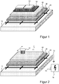
- Reference numeral 10 denotes a section of a carrier layer made of (dried) concrete, which forms a bottom of a swimming pool (not shown) and thus a surface to be sealed.
- a network 20 of self-adhesive conductor tapes with a mesh width of five meters is glued onto the carrier layer 10.
- the individual conduction tapes are made of copper foil with a thickness of 35 ⁇ m and a width of 2 centimeters.
- the network 20 is connected to a ground, not shown.
- first conductive layer 30 Arranged over the network 20 is a 2 mm thick full-area first conductive layer 30 which is formed by adding 25 kg of the product "Sopro's No.1 Flex adhesive - No.1 400" together with 3.75 kg of the product "Sopro ELD 458 Electra Leitdispersion " processed.
- the network 20 is thus partially embedded in the first conductive layer 30 and is in electrical contact with the surface thereof.
- the surface resistance of the first layer 30, determined according to DIN EN 61340-4-1 VDE 0300-4-1: 2016-04, is after a drying time of seven days at 23 ° C and 50% relative humidity (and thus after the first layer has hardened 30) 10 4 ⁇ .
- the first layer 30 thus has a significantly increased conductivity compared to cement and also compared to the carrier layer 10.
- a full-surface, second waterproof and non-conductive layer 40 with a layer thickness of 3 millimeters is arranged on this first layer 30, a full-surface, second waterproof and non-conductive layer 40 with a layer thickness of 3 millimeters is arranged.
- this is formed by applying the product "Sopro TDS 823 TuboDichtSchlämme 2-K" in three work steps .
- the second layer After a drying time of three days at 23 ° C and 50% relative humidity and thus after curing, the second layer has a volume resistance of 10 8 ⁇ measured according to DIN EN 61340-4-1 VDE 0300-4-1: 2016-04 . Due to the properties of the product "Sopro TDS 823 TuboDichtSchlämme 2-K" the second layer has a water impact class of W3-I determined according to DIN 18534-1 - 2017-07.
- the second layer 40 carries over a 2 millimeter thick layer of conventional tile adhesive 50 (for which the product "Sopro's No.1 Flex adhesive - No.1 400" was used again) ceramic tiles 60. These are in Figure 1 not yet available and form the wear layer of the layer structure. In particular, the tiles protect the second waterproof layer 40 from mechanical damage.
- the layer of tile adhesive described above is only optional and can vary in thickness between 1 millimeter and 20 millimeters.
- the non-conductive, waterproof second layer 40 can alternatively be formed on the basis of polyurethane.
- the product "Sopro PU-FD PU surface seal" can be used for this layer.
- Figure 2 a method for checking the layer structure Figure 1 described. As can be seen from a comparison of the Figures 1 and 2 results, this method is carried out after the curing and drying of the second layer 40, and thus before the second layer 40 is covered with tile adhesive 50 and tiles 60.
- a high-voltage test device 70 is connected via electrical lines 71, 72 to a test electrode 72 in the form of a measuring brush.
- the network 20 is permanently earthed.
- the high-voltage test device 70 is designed to apply a high voltage of up to 8 kV between the network 20 and the test electrode 72, but in doing so to limit a possible current flow to a level that is harmless to humans.
- a corresponding device can be obtained under the name ELMED Isotest Inspect 8.0 from the ELMED Dr. Ing. Mense GmbH, Weilenburgstrasse 39, D-42579 Heiligenhaus.
- the surface of the second waterproof layer 40 is scanned by a user by means of the test electrode 72 having a brass broom at a speed of around 30 centimeters per second.
- the high-voltage test device 70 detects an electrical discharge between the test electrode 72 and the network 20, this is signaled visually and acoustically via a display 74.
- the user recognizes that the second layer 40 has a poor seal at the point where the brass broom of the test electrode 72 was located at the time of the signal.
- This weak point of the second layer 40 can then be remedied by increasing the thickness of the second layer 401 in this area.
- the above leak test can be carried out in accordance with DIN 55670: 2011-02.
Landscapes
- Physics & Mathematics (AREA)
- Engineering & Computer Science (AREA)
- Architecture (AREA)
- Electromagnetism (AREA)
- Civil Engineering (AREA)
- Structural Engineering (AREA)
- General Physics & Mathematics (AREA)
- Laminated Bodies (AREA)
- Building Environments (AREA)
Applications Claiming Priority (1)
| Application Number | Priority Date | Filing Date | Title |
|---|---|---|---|
| DE102018123902.5A DE102018123902A1 (de) | 2018-09-27 | 2018-09-27 | Flüssigkeitsdichter Schichtaufbau und Verfahren zur Herstellung und Prüfung desselben |
Publications (3)
| Publication Number | Publication Date |
|---|---|
| EP3628788A1 true EP3628788A1 (fr) | 2020-04-01 |
| EP3628788B1 EP3628788B1 (fr) | 2023-06-07 |
| EP3628788C0 EP3628788C0 (fr) | 2023-06-07 |
Family
ID=68072192
Family Applications (1)
| Application Number | Title | Priority Date | Filing Date |
|---|---|---|---|
| EP19199973.9A Active EP3628788B1 (fr) | 2018-09-27 | 2019-09-26 | Structure en couches étanche aux fluides et procédé de fabrication d'une telle structure |
Country Status (3)
| Country | Link |
|---|---|
| EP (1) | EP3628788B1 (fr) |
| DE (1) | DE102018123902A1 (fr) |
| PL (1) | PL3628788T3 (fr) |
Citations (5)
| Publication number | Priority date | Publication date | Assignee | Title |
|---|---|---|---|---|
| DE1145337B (de) | 1957-07-24 | 1963-03-14 | Hoffmann & Hartl | Abdichtung von Bauwerksteilen gegen Wasser und Vorrichtung zu ihrer Pruefung |
| DE2446979A1 (de) | 1974-10-02 | 1976-04-15 | Zaiss Gmbh Karl | Auf dichtigkeit pruefbare abdichtung von bauwerksteilen gegen wasser |
| EP0228004A2 (fr) * | 1985-12-21 | 1987-07-08 | Henkel Kommanditgesellschaft auf Aktien | Revêtement de sol conducteur d'électricité |
| DE19724296A1 (de) * | 1997-06-09 | 1998-12-10 | Rundmund Gmbh | Flüssigkeitsdichter Boden- oder Wandbelag aus keramischen Platten |
| DE102010040978A1 (de) * | 2010-09-17 | 2012-03-22 | MFT Münster Fertigungstechnik GmbH & Co. KG | Bodenbeschichtung, auf Dichtigkeit prüfbarer Bodenbelag, Einrichtung zum Auffangen von Flüssigkeiten und Anordnung zum Galvanisieren sowie Verfahren zum Herstellen und zum Prüfen der Dichtigkeit |
-
2018
- 2018-09-27 DE DE102018123902.5A patent/DE102018123902A1/de not_active Withdrawn
-
2019
- 2019-09-26 EP EP19199973.9A patent/EP3628788B1/fr active Active
- 2019-09-26 PL PL19199973.9T patent/PL3628788T3/pl unknown
Patent Citations (5)
| Publication number | Priority date | Publication date | Assignee | Title |
|---|---|---|---|---|
| DE1145337B (de) | 1957-07-24 | 1963-03-14 | Hoffmann & Hartl | Abdichtung von Bauwerksteilen gegen Wasser und Vorrichtung zu ihrer Pruefung |
| DE2446979A1 (de) | 1974-10-02 | 1976-04-15 | Zaiss Gmbh Karl | Auf dichtigkeit pruefbare abdichtung von bauwerksteilen gegen wasser |
| EP0228004A2 (fr) * | 1985-12-21 | 1987-07-08 | Henkel Kommanditgesellschaft auf Aktien | Revêtement de sol conducteur d'électricité |
| DE19724296A1 (de) * | 1997-06-09 | 1998-12-10 | Rundmund Gmbh | Flüssigkeitsdichter Boden- oder Wandbelag aus keramischen Platten |
| DE102010040978A1 (de) * | 2010-09-17 | 2012-03-22 | MFT Münster Fertigungstechnik GmbH & Co. KG | Bodenbeschichtung, auf Dichtigkeit prüfbarer Bodenbelag, Einrichtung zum Auffangen von Flüssigkeiten und Anordnung zum Galvanisieren sowie Verfahren zum Herstellen und zum Prüfen der Dichtigkeit |
Also Published As
| Publication number | Publication date |
|---|---|
| EP3628788B1 (fr) | 2023-06-07 |
| PL3628788T3 (pl) | 2024-01-22 |
| EP3628788C0 (fr) | 2023-06-07 |
| DE102018123902A1 (de) | 2020-04-02 |
Similar Documents
| Publication | Publication Date | Title |
|---|---|---|
| DE69419895T2 (de) | Verfahren und Vorrichtung für den kathodischen Schutz von armierten Betonstrukturen | |
| DE2225358C2 (de) | Vorgefertigtes bogen- oder bahnförmiges Material | |
| DE102013018917A1 (de) | System und Verfahren zur Überwachung eines Untergrundes hinsichtlich Schäden und/oder zum Schutz eines Untergrundes vor Schäden | |
| EP3253722A1 (fr) | Mélange de matériaux de construction | |
| EP3628788B1 (fr) | Structure en couches étanche aux fluides et procédé de fabrication d'une telle structure | |
| DE1659911B2 (de) | Verfahren zum Verfugen von Plattenbelägen aus keramischem Material mit organischen Kunstharzkitten des Säureschutzbaues | |
| DE2536565C3 (de) | Stahlpanzerrohr zur Aufnahme elektrischer Leiter | |
| DE102008043640A1 (de) | Fußbodenaufbau mit thermischer Dämmung und Schalldämmung | |
| DE29618481U1 (de) | Isolier-Tapete | |
| DE202014103218U1 (de) | Wasser-Hinterlauf-sichere Wärmedämmung für ein Bauwerk | |
| DE4134752A1 (de) | Beschichtungssystem fuer mit fluessigkeiten belastbare flaechen | |
| EP3771907B1 (fr) | Procédé de détermination de la teneur en humidité du béton et de la chape | |
| DE2445737A1 (de) | Elektrostatische ladungen ableitendes gewebe | |
| EP1669511A1 (fr) | Elément léger de construction et son procédé de fabrication | |
| DE102019128891B3 (de) | Wiederaufnahmefähiger Bodenaufbau mit Fliesen und Verfahren zur Errichtung desselben | |
| DE102013105737A1 (de) | Vorrichtung und Verfahren zur Abdichtung einer Innenwand | |
| DE2549993A1 (de) | Bauwerksbeschichtung | |
| DE2321408A1 (de) | Selbstverlaufender und selbstnivellierender kunststoff/zement-moertel | |
| DE202019105945U1 (de) | Wiederaufnahmefähiger Bodenaufbau mit Fliesen | |
| DE102009044266A1 (de) | Dichtelement und dessen Verwendung | |
| DE2458802A1 (de) | Verfahren zur herstellung elektrostatische ladungen ableitender belaege | |
| DE2148448A1 (de) | Dichtungsbelag für Bauelemente und Bauwerke | |
| DE202013102396U1 (de) | Vorrichtung zur Abdichtung einer Innenwand | |
| CH686722A5 (de) | Verfahren zum Abdichten und Schuetzen von Auffangwannen und Behaeltern. | |
| DE8616698U1 (de) | Chemisch beständiger, flüssigkeitsdichter Belag |
Legal Events
| Date | Code | Title | Description |
|---|---|---|---|
| PUAI | Public reference made under article 153(3) epc to a published international application that has entered the european phase |
Free format text: ORIGINAL CODE: 0009012 |
|
| STAA | Information on the status of an ep patent application or granted ep patent |
Free format text: STATUS: THE APPLICATION HAS BEEN PUBLISHED |
|
| AK | Designated contracting states |
Kind code of ref document: A1 Designated state(s): AL AT BE BG CH CY CZ DE DK EE ES FI FR GB GR HR HU IE IS IT LI LT LU LV MC MK MT NL NO PL PT RO RS SE SI SK SM TR |
|
| AX | Request for extension of the european patent |
Extension state: BA ME |
|
| STAA | Information on the status of an ep patent application or granted ep patent |
Free format text: STATUS: REQUEST FOR EXAMINATION WAS MADE |
|
| 17P | Request for examination filed |
Effective date: 20200507 |
|
| RBV | Designated contracting states (corrected) |
Designated state(s): AL AT BE BG CH CY CZ DE DK EE ES FI FR GB GR HR HU IE IS IT LI LT LU LV MC MK MT NL NO PL PT RO RS SE SI SK SM TR |
|
| GRAP | Despatch of communication of intention to grant a patent |
Free format text: ORIGINAL CODE: EPIDOSNIGR1 |
|
| STAA | Information on the status of an ep patent application or granted ep patent |
Free format text: STATUS: GRANT OF PATENT IS INTENDED |
|
| RIC1 | Information provided on ipc code assigned before grant |
Ipc: G01M 3/16 20060101ALI20220209BHEP Ipc: E04B 1/66 20060101AFI20220209BHEP |
|
| INTG | Intention to grant announced |
Effective date: 20220311 |
|
| RIN1 | Information on inventor provided before grant (corrected) |
Inventor name: ROSENAU, BJOERN |
|
| GRAJ | Information related to disapproval of communication of intention to grant by the applicant or resumption of examination proceedings by the epo deleted |
Free format text: ORIGINAL CODE: EPIDOSDIGR1 |
|
| GRAL | Information related to payment of fee for publishing/printing deleted |
Free format text: ORIGINAL CODE: EPIDOSDIGR3 |
|
| GRAS | Grant fee paid |
Free format text: ORIGINAL CODE: EPIDOSNIGR3 |
|
| STAA | Information on the status of an ep patent application or granted ep patent |
Free format text: STATUS: REQUEST FOR EXAMINATION WAS MADE |
|
| GRAP | Despatch of communication of intention to grant a patent |
Free format text: ORIGINAL CODE: EPIDOSNIGR1 |
|
| STAA | Information on the status of an ep patent application or granted ep patent |
Free format text: STATUS: GRANT OF PATENT IS INTENDED |
|
| INTC | Intention to grant announced (deleted) | ||
| INTG | Intention to grant announced |
Effective date: 20220817 |
|
| GRAA | (expected) grant |
Free format text: ORIGINAL CODE: 0009210 |
|
| STAA | Information on the status of an ep patent application or granted ep patent |
Free format text: STATUS: THE PATENT HAS BEEN GRANTED |
|
| AK | Designated contracting states |
Kind code of ref document: B1 Designated state(s): AL AT BE BG CH CY CZ DE DK EE ES FI FR GB GR HR HU IE IS IT LI LT LU LV MC MK MT NL NO PL PT RO RS SE SI SK SM TR |
|
| REG | Reference to a national code |
Ref country code: GB Ref legal event code: FG4D Free format text: NOT ENGLISH |
|
| REG | Reference to a national code |
Ref country code: CH Ref legal event code: EP Ref country code: AT Ref legal event code: REF Ref document number: 1575435 Country of ref document: AT Kind code of ref document: T Effective date: 20230615 |
|
| REG | Reference to a national code |
Ref country code: DE Ref legal event code: R096 Ref document number: 502019007928 Country of ref document: DE |
|
| U01 | Request for unitary effect filed |
Effective date: 20230613 |
|
| U07 | Unitary effect registered |
Designated state(s): AT BE BG DE DK EE FI FR IT LT LU LV MT NL PT SE SI Effective date: 20230620 |
|
| U20 | Renewal fee for the european patent with unitary effect paid |
Year of fee payment: 5 Effective date: 20230725 |
|
| REG | Reference to a national code |
Ref country code: LT Ref legal event code: MG9D |
|
| REG | Reference to a national code |
Ref country code: NO Ref legal event code: T2 Effective date: 20230607 |
|
| PG25 | Lapsed in a contracting state [announced via postgrant information from national office to epo] |
Ref country code: ES Free format text: LAPSE BECAUSE OF FAILURE TO SUBMIT A TRANSLATION OF THE DESCRIPTION OR TO PAY THE FEE WITHIN THE PRESCRIBED TIME-LIMIT Effective date: 20230607 |
|
| PG25 | Lapsed in a contracting state [announced via postgrant information from national office to epo] |
Ref country code: RS Free format text: LAPSE BECAUSE OF FAILURE TO SUBMIT A TRANSLATION OF THE DESCRIPTION OR TO PAY THE FEE WITHIN THE PRESCRIBED TIME-LIMIT Effective date: 20230607 Ref country code: HR Free format text: LAPSE BECAUSE OF FAILURE TO SUBMIT A TRANSLATION OF THE DESCRIPTION OR TO PAY THE FEE WITHIN THE PRESCRIBED TIME-LIMIT Effective date: 20230607 Ref country code: GR Free format text: LAPSE BECAUSE OF FAILURE TO SUBMIT A TRANSLATION OF THE DESCRIPTION OR TO PAY THE FEE WITHIN THE PRESCRIBED TIME-LIMIT Effective date: 20230908 |
|
| PG25 | Lapsed in a contracting state [announced via postgrant information from national office to epo] |
Ref country code: SK Free format text: LAPSE BECAUSE OF FAILURE TO SUBMIT A TRANSLATION OF THE DESCRIPTION OR TO PAY THE FEE WITHIN THE PRESCRIBED TIME-LIMIT Effective date: 20230607 |
|
| PG25 | Lapsed in a contracting state [announced via postgrant information from national office to epo] |
Ref country code: SM Free format text: LAPSE BECAUSE OF FAILURE TO SUBMIT A TRANSLATION OF THE DESCRIPTION OR TO PAY THE FEE WITHIN THE PRESCRIBED TIME-LIMIT Effective date: 20230607 Ref country code: SK Free format text: LAPSE BECAUSE OF FAILURE TO SUBMIT A TRANSLATION OF THE DESCRIPTION OR TO PAY THE FEE WITHIN THE PRESCRIBED TIME-LIMIT Effective date: 20230607 Ref country code: RO Free format text: LAPSE BECAUSE OF FAILURE TO SUBMIT A TRANSLATION OF THE DESCRIPTION OR TO PAY THE FEE WITHIN THE PRESCRIBED TIME-LIMIT Effective date: 20230607 Ref country code: CZ Free format text: LAPSE BECAUSE OF FAILURE TO SUBMIT A TRANSLATION OF THE DESCRIPTION OR TO PAY THE FEE WITHIN THE PRESCRIBED TIME-LIMIT Effective date: 20230607 |
|
| REG | Reference to a national code |
Ref country code: DE Ref legal event code: R097 Ref document number: 502019007928 Country of ref document: DE |
|
| PLBE | No opposition filed within time limit |
Free format text: ORIGINAL CODE: 0009261 |
|
| STAA | Information on the status of an ep patent application or granted ep patent |
Free format text: STATUS: NO OPPOSITION FILED WITHIN TIME LIMIT |
|
| 26N | No opposition filed |
Effective date: 20240308 |
|
| PG25 | Lapsed in a contracting state [announced via postgrant information from national office to epo] |
Ref country code: MC Free format text: LAPSE BECAUSE OF FAILURE TO SUBMIT A TRANSLATION OF THE DESCRIPTION OR TO PAY THE FEE WITHIN THE PRESCRIBED TIME-LIMIT Effective date: 20230607 |
|
| U20 | Renewal fee for the european patent with unitary effect paid |
Year of fee payment: 6 Effective date: 20240910 |
|
| PG25 | Lapsed in a contracting state [announced via postgrant information from national office to epo] |
Ref country code: CY Free format text: LAPSE BECAUSE OF FAILURE TO SUBMIT A TRANSLATION OF THE DESCRIPTION OR TO PAY THE FEE WITHIN THE PRESCRIBED TIME-LIMIT; INVALID AB INITIO Effective date: 20190926 |
|
| PG25 | Lapsed in a contracting state [announced via postgrant information from national office to epo] |
Ref country code: HU Free format text: LAPSE BECAUSE OF FAILURE TO SUBMIT A TRANSLATION OF THE DESCRIPTION OR TO PAY THE FEE WITHIN THE PRESCRIBED TIME-LIMIT; INVALID AB INITIO Effective date: 20190926 |
|
| U20 | Renewal fee for the european patent with unitary effect paid |
Year of fee payment: 7 Effective date: 20250717 |
|
| REG | Reference to a national code |
Ref country code: CH Ref legal event code: U11 Free format text: ST27 STATUS EVENT CODE: U-0-0-U10-U11 (AS PROVIDED BY THE NATIONAL OFFICE) Effective date: 20251001 |
|
| PGFP | Annual fee paid to national office [announced via postgrant information from national office to epo] |
Ref country code: NO Payment date: 20250717 Year of fee payment: 7 |
|
| PGFP | Annual fee paid to national office [announced via postgrant information from national office to epo] |
Ref country code: PL Payment date: 20250717 Year of fee payment: 7 |
|
| PGFP | Annual fee paid to national office [announced via postgrant information from national office to epo] |
Ref country code: GB Payment date: 20250716 Year of fee payment: 7 |
|
| PGFP | Annual fee paid to national office [announced via postgrant information from national office to epo] |
Ref country code: IE Payment date: 20250716 Year of fee payment: 7 |
|
| PGFP | Annual fee paid to national office [announced via postgrant information from national office to epo] |
Ref country code: IS Payment date: 20250716 Year of fee payment: 7 |
|
| PG25 | Lapsed in a contracting state [announced via postgrant information from national office to epo] |
Ref country code: TR Free format text: LAPSE BECAUSE OF FAILURE TO SUBMIT A TRANSLATION OF THE DESCRIPTION OR TO PAY THE FEE WITHIN THE PRESCRIBED TIME-LIMIT Effective date: 20230607 |
|
| PGFP | Annual fee paid to national office [announced via postgrant information from national office to epo] |
Ref country code: CH Payment date: 20251001 Year of fee payment: 7 |