EP3628792A1 - Profilé de masticage - Google Patents
Profilé de masticage Download PDFInfo
- Publication number
- EP3628792A1 EP3628792A1 EP19193162.5A EP19193162A EP3628792A1 EP 3628792 A1 EP3628792 A1 EP 3628792A1 EP 19193162 A EP19193162 A EP 19193162A EP 3628792 A1 EP3628792 A1 EP 3628792A1
- Authority
- EP
- European Patent Office
- Prior art keywords
- spatula
- profile
- embossed structure
- longitudinal direction
- embossed
- Prior art date
- Legal status (The legal status is an assumption and is not a legal conclusion. Google has not performed a legal analysis and makes no representation as to the accuracy of the status listed.)
- Pending
Links
Images



Classifications
-
- E—FIXED CONSTRUCTIONS
- E04—BUILDING
- E04F—FINISHING WORK ON BUILDINGS, e.g. STAIRS, FLOORS
- E04F13/00—Coverings or linings, e.g. for walls or ceilings
- E04F13/02—Coverings or linings, e.g. for walls or ceilings of plastic materials hardening after applying, e.g. plaster
- E04F13/04—Bases for plaster
- E04F13/045—Means for fastening plaster-bases to a supporting structure
-
- E—FIXED CONSTRUCTIONS
- E04—BUILDING
- E04F—FINISHING WORK ON BUILDINGS, e.g. STAIRS, FLOORS
- E04F13/00—Coverings or linings, e.g. for walls or ceilings
- E04F13/02—Coverings or linings, e.g. for walls or ceilings of plastic materials hardening after applying, e.g. plaster
- E04F13/04—Bases for plaster
- E04F13/06—Edge-protecting borders
- E04F13/068—Edge-protecting borders combined with mesh material or the like to allow plaster to bond therewith
-
- E—FIXED CONSTRUCTIONS
- E04—BUILDING
- E04F—FINISHING WORK ON BUILDINGS, e.g. STAIRS, FLOORS
- E04F13/00—Coverings or linings, e.g. for walls or ceilings
- E04F13/02—Coverings or linings, e.g. for walls or ceilings of plastic materials hardening after applying, e.g. plaster
- E04F13/04—Bases for plaster
- E04F13/06—Edge-protecting borders
- E04F2013/063—Edge-protecting borders for corners
Definitions
- the present invention relates to a spatula profile, in particular an edge angle or a finishing profile, which preferably comprises paper and / or plastic.
- spatula profiles are typically made of metal, spatula profiles can in principle also comprise other materials.
- Filler profiles can be a plastic, e.g. PVC, include.
- spatula profiles can also be made of paper or at least have paper portions.
- a spatula profile can be a plastic core, e.g. a plastic film, which is covered on both sides with a paper layer, for example by flocking the soul with paper fibers.
- Such spatula profiles can be advantageous over spatula profiles made of metal in terms of weight, cost and environmental aspects.
- Trowel profiles with plastic surfaces and in particular trowel profiles with paper surfaces can, however, be problematic with regard to the adhesion of filler, such as plaster, to the surfaces of the respective trowel profile, especially if they have surfaces made of plastic and / or paper. This can affect both surfaces on the side of the spatula profile facing a respective wall and surfaces on the side of the spatula profile facing away from the respective wall.
- spatula profiles in particular spatula profiles comprising paper and / or plastic, which are particularly reliable Allow putty, especially plaster, to be bonded to the respective filler profile.
- the spatula profile which is in particular an edge angle, an end profile or a base profile and which preferably comprises paper and / or plastic, extends along a longitudinal direction and comprises at least one surface which has an embossed structure, the embossed structure is at least partially linear.
- embossing for example compared to extrusion, has the advantage that a filler profile can also be subsequently provided with a structure that is advantageous for the bonding of filler compound.
- embossed structures are not limited to a continuous course in the longitudinal direction.
- the embossed structures are advantageously linear, at least in some areas, in order to provide a large number of edges on the surface for engagement of the filler.
- the embossed linear elements i.e. the line-shaped sections of the embossed structure, unlike extruded line structures, advantageously be oriented on the respective surface of the spatula profile, particularly with a view to a later assembly orientation of the spatula profile, in particular with regard to the gravity acting in the process.
- the spatula profile can have an at least substantially constant cross section perpendicular to its longitudinal extent.
- the surface in which the above-mentioned embossed structure is formed and which is in particular extending in the longitudinal direction is, moreover, preferably flat.
- the structure can be impressed into the surface by pressure forming, in particular by chipless pressing into the surface.
- An embossed structure can therefore differ from a corresponding structure produced by extrusion (if the respective structure can be produced by extrusion at all) by a higher material density in the pressed-in areas of the surface.
- the higher material density can contribute to the stiffening of the filler profile, which (in addition to the possibility of subsequently introducing the structure into the surface) represents a further advantage of an embossed structure compared to a corresponding structure produced by extrusion.
- the embossing takes place, for example, as roller embossing.
- the line-shaped elements of the embossed structure can in particular each have an at least substantially constant line width, wherein the line width can be the same for all line-shaped elements.
- a respective linear element does not necessarily have to have a straight course, but can also have an at least partially curved course.
- the embossed structure can be provided on a surface of the spatula profile which, when the spatula profile is mounted, faces a wall or another component on which the spatula profile is arranged, or on a surface which faces away from the wall or the other component.
- the spatula profile both on one or more surfaces facing a wall or other component on which the spatula profile is arranged when the spatula profile is mounted, as well as on one or more surfaces facing away from the wall or the other component are facing away, each have an embossed structure of the type mentioned.
- the embossed structure comprises one or more linear elements, the respective course of which is at least partially oriented transversely to the longitudinal direction.
- a course of a linear element oriented transversely to the longitudinal direction can offer good hold for a filler, particularly in the longitudinal direction.
- Such an embodiment is therefore particularly advantageous for edge angles, which are typically arranged at vertical corners of a component.
- the linear elements of the embossed structure are, in particular, grooves.
- the grooves can be formed as grooves recessed in the surface.
- the grooves can in principle also be designed as protruding grooves, for example by deepening adjacent areas of the surface by embossing or by embossing by pressing in from the back of the surface, i.e. from a surface of the spatula profile opposite to the surface, so that the grooves are pressed out of the surface.
- the embossed structure also includes non-linear elements in addition to linear elements.
- the non-linear elements can, for example, be surfaces or shapes that do not define a clear line course.
- the non-linear elements are also not strip-shaped.
- elements of a surface structure that are not linear cannot be produced by extrusion.
- the embossed structure comprises at least two linear elements which intersect, in particular several times. Such intersections offer the filler a multitude of edges aligned in different directions, on which the filler can engage. In this way, an improved claw can be achieved.
- the embossed structure is repeated periodically in the longitudinal direction.
- the adhesiveness of the surface can be at least largely homogeneous over the longitudinal extent of the spatula profile.
- a periodically repeating structure can be achieved in particular by roll stamping.
- the embossed structure is mirror-symmetrical to a mirror axis that is parallel to the longitudinal direction.
- the mirror axis can in particular correspond to a center line of the surface with respect to its width transverse to the longitudinal direction.
- the spatula profile can have at least two surfaces which have embossed structures that are structurally identical or mirror-symmetrical to one another. If the two surfaces have different dimensions, the embossed structures can be structurally identical or mirror-symmetrical, at least in some areas, that is, they can be based on corresponding repetitive patterns.
- the two surfaces can be angled to each other. If the spatula profile is designed as an edge angle, the surfaces can in particular be its outer surfaces, between which the free angle is more than 180 °, or its inner surfaces, between which the free angle is less than 180 °.
- At least one surface of the spatula profile has openings.
- the openings can improve the clawing of the filler on the filler profile, since the filler can penetrate through the openings.
- Such openings are preferred with respect to the longitudinal direction arranged regularly distributed.
- the openings can be arranged at regular intervals from one another in the longitudinal direction.
- the openings are completely or individually surrounded by linear elements of the embossed structure. Some of the openings can be individually enclosed and another part of the openings in groups can be completely enclosed by linear elements of the embossed structure. In this way, the openings and the embossed structure can advantageously complement each other. In particular, the embossed structure is not interrupted by the openings.
- the spatula profiles 11 each have a core made of a plastic film with a thickness of 0.2 mm, which is flocked with paper fibers or coated in another way, for example.
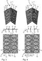
- the spatula profiles 11 each extend along a longitudinal direction L and comprise two surface sections 13 of the same width, which are oriented at an angle to one another (cf. in the figures in each case above).
- the surface sections 13 can be connected to one another in a bendable manner, so that they can also assume the flat state shown in the figures in the middle and below, in which the surface sections 13 lie in one plane.
- the angled arrangement can also be rigid.
- the spatula profile 11 is not shown in its entirety, but is shown in a shortened form with respect to its length, ie the extent in the longitudinal direction L.
- the spatula profile 11 can be one-sided over the section shown in each case or extend significantly further on both sides in the longitudinal direction L.
- the spatula profile 11 has a length of the order of a few meters, for example 1 m, 1.5 m, 2 m. 2.5 m or longer, and can be cut to length depending on actual needs.
- the section of the respective spatula profile 11 shown is an example of the formation of the spatula profile 11 over its entire length. In other words, the illustrated embodiment can at least essentially continue or repeat in the longitudinal direction L on one side or on both sides.
- each surface 15 of the surface sections 13 of the spatula profile 11 is provided with an embossed structure 17, which was produced by chipless pressing into the respective surface 15.
- the structure 17 embossed into the surface 15 of the one surface section 13 of the respective spatula profile 11 and the structure 17 embossed into the surface 15 of the other surface section 13 of the respective spatula profile 11 are each identical to one another.
- each surface section 13 can be provided not only on one side but also on both sides with a respective embossed structure 17, the embossed structures 17 on opposite surfaces 15 of the same surface section 13 then preferably being mirror-symmetrical with respect to a plane parallel to the surfaces 15.
- the spatula profiles 11 are preferably each mirror-symmetrical to a plane bisecting the angle between the two surface sections 13.
- the embossed structures 17 of all the spatula profiles 11 shown are each linear at least in some areas, so that they each comprise linear elements 19. In the embodiments shown, the embossed structures 17 each have exclusively linear elements 19. In principle, however, the embossed structure 17 can also comprise non-linear elements.
- the embossed structures 17 of a respective surface 15 are each mirror-symmetrical to a center line of the respective surface 15 with respect to their respective width transverse to the longitudinal direction L.
- the different in the 1 to 6 Filler profiles 11 shown differ only in relation to the respective design of the embossed structures 17 and, if appropriate, to the respective design of openings 21 provided in the surface sections 13 1 and 2 , 3 and 4 and FIGS. 5 and 6 each in pairs two largely corresponding embodiments, one of which has an embossed structure 17 without openings 21 and the other of which has the same embossed structure 17 with openings 21 arranged therebetween.
- the linear elements 19 are in the embodiments according to FIGS 1 and 2 completely and in the embodiments according to the 3 to 6 almost completely (apart from the lateral vertices of the curved courses) aligned transversely to the longitudinal direction L and cross each other several times.
- the linear elements 19 in the embodiments according to FIGS 1 and 2 a line shape that corresponds to a triangular wave. In total, six triangular oscillations overlap each other with a phase shift of one sixth period each.
- the line-shaped elements 19 each have a line shape which corresponds to a sine wave. Overlap in the embodiments according to the 3 and 4 in each case two sine waves with a phase shift of half a period each other, while in the embodiments according to the 5 and 6 superimpose four sine waves with a phase shift of a quarter period each.
- the openings 21 are circular. In this case, in each of the line-shaped elements 19 which cross each other enclosed square fields each provided an opening 21. In the embodiment according to Fig. 4 the openings 21 also each have a circular shape.
- the intersecting line-shaped elements 19 include fields in which four openings 21 are arranged. In the embodiment according to Fig. 6 the openings have an elongated oval shape which is oriented perpendicular to the longitudinal direction L.
- the intersecting line-shaped elements 19 enclose two types of fields which have three or four corners and have approximately a triangular shape or a diamond shape.
- One opening 21 is provided in each of the fields with a triangular shape, while two openings 21 are provided in the fields with a diamond shape.
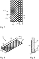
- spatula profile 11 serves to end the component 23 (cf. Fig. 9 or 12) and can be used as base profiles.
- the spatula profile 11 can in particular be designed to be arranged on a plate-shaped component 23 and to grip around the component 23 at one end.
- the component 23 can be, for example, a plasterboard or other building board, which can also be made of wood or composite materials.
- the two in the 7 to 12 Filler profiles 11 shown can in principle in a corresponding manner as that in the 1 to 6 filler profiles 11 shown be formed.
- the spatula profiles 11 can each have a core made of a plastic film, which is flocked with paper fibers or coated in some other way, for example, extend along a longitudinal direction L and comprise a plurality of surface sections 13 which, at least in the assembled state, are oriented at an angle to one another.
- the in the 7 to 12 shown end profiles each have more than two surface sections 13, which are defined by longitudinal edges on which the respective spatula profile 11 is bent. This allows the respective spatula profile 11, as in the Fig. 9 or 12 shown, encompass a component 23.
- the embodiment according to the 7 to 9 has three surface sections 13 are in the embodiment according to the 10 to 12 to distinguish four surface sections 13. While the two outer surface sections 13 of the embodiment according to FIGS 10 to 12 in terms of their dimensions and function, essentially the two outer surface sections 13 of the embodiment according to FIGS 7 to 9 correspond, the embodiment according to the 10 to 12 two middle surface sections 13, namely a first middle surface section 13, one opposite the middle surface section of the embodiment according to FIGS 7 to 9 has increased width, and additionally a second central surface section 13 which is aligned at an acute angle to the first central surface section 13. As a result, the two outer surface sections 13 can lie flat on the component 23 on both sides, although the first middle surface section 13 is wider than the width of the component 23. At the same time, the longitudinal edge between the two middle surface sections 13 protrudes from the component 23, so that it advantageously as a pull-off edge 25 (cf. Fig. 12 ) can be used for plastering.
- a pull-off edge 25 cf. Fig. 12
- Several surfaces 15 of the surface sections 13 of the two in the 7 to 12 spatula profiles 11 shown are provided in the manner according to the invention with a line-shaped embossed structure 17.
- the embossed structure 17 corresponds to that of FIG Fig. 1 shown embodiment.
- the two spatula profiles 11 could also be one of the other, in which 2 to 6 Embossed structures 17 shown, optionally with corresponding openings 21, or have another embossed structure 17 which is at least partially linear in shape.
- the two spatula profiles 11 shown are each provided with an embossed structure 17 on at least one side of all surface sections 13 (cf. Fig. 7 or 10). At least one of the surface sections 13 has an embossed structure 17 only on one side, so that a surface 15 'of this surface section 13 has no embossed structure 17 (cf. Fig. 8 or 11). Which of the surfaces 15 are provided with an embossed structure 17 and which are not can depend on where an improvement in the clawing is particularly expedient.
- the figures only show examples in this regard. Basically, the surfaces 15 with embossed structures 17 and the surfaces 15 'without embossed structures 17 can also be distributed on a respective spatula profile 11 in a manner other than that shown.
- the structures described can be embossed in the manner described 17 provided surfaces 15 filler profiles according to the invention 11 better grip and adhere filler. In this way, a particularly reliable clawing of the filler on the respective filler profile 11 is achieved by the inventive design.
Landscapes
- Engineering & Computer Science (AREA)
- Architecture (AREA)
- Civil Engineering (AREA)
- Structural Engineering (AREA)
- Coating Apparatus (AREA)
- Finishing Walls (AREA)
Applications Claiming Priority (1)
| Application Number | Priority Date | Filing Date | Title |
|---|---|---|---|
| DE102018124058.9A DE102018124058A1 (de) | 2018-09-28 | 2018-09-28 | Spachtelprofil |
Publications (1)
| Publication Number | Publication Date |
|---|---|
| EP3628792A1 true EP3628792A1 (fr) | 2020-04-01 |
Family
ID=67734588
Family Applications (1)
| Application Number | Title | Priority Date | Filing Date |
|---|---|---|---|
| EP19193162.5A Pending EP3628792A1 (fr) | 2018-09-28 | 2019-08-22 | Profilé de masticage |
Country Status (2)
| Country | Link |
|---|---|
| EP (1) | EP3628792A1 (fr) |
| DE (1) | DE102018124058A1 (fr) |
Citations (4)
| Publication number | Priority date | Publication date | Assignee | Title |
|---|---|---|---|---|
| US3201908A (en) * | 1961-10-06 | 1965-08-24 | Alfred F Arnold | Corner screed bead |
| US6295776B1 (en) * | 2000-05-17 | 2001-10-02 | Phillips Manufacturing Co. | Corner bead drywall trim and method of manufacture |
| US6360503B1 (en) * | 2000-12-28 | 2002-03-26 | Trim-Tex, Inc. | Drywall-trimming accessory having break-away panes |
| US20090205279A1 (en) * | 2008-02-18 | 2009-08-20 | Trim-Tex, Inc. | Drywall trimming element with compound locking feature |
Family Cites Families (5)
| Publication number | Priority date | Publication date | Assignee | Title |
|---|---|---|---|---|
| DE19539527C2 (de) * | 1995-10-24 | 2001-02-22 | August Braun | Winkelleiste mit Armierungsmaterial für den Putz auf einer Wärmedämmung |
| DE29722571U1 (de) * | 1997-12-20 | 1998-03-05 | Protektorwerk Florenz Maisch GmbH & Co. KG, 76571 Gaggenau | Kantenschutzband |
| DE29914064U1 (de) * | 1999-08-12 | 2000-04-06 | Braun, August, Schaffhausen | Anordnung von Putz-Eckleisten an einer Bauwerksecke |
| DE20210443U1 (de) * | 2002-07-05 | 2002-09-05 | Wörner, Eckard, 72805 Lichtenstein | Einputzwinkel als Eckbewehrung |
| CZ28626U1 (cs) * | 2015-07-27 | 2015-09-07 | Mateiciuc A.S. | Stavební profil s povrchovou úpravou ke zvýšení adheze omítky |
-
2018
- 2018-09-28 DE DE102018124058.9A patent/DE102018124058A1/de active Pending
-
2019
- 2019-08-22 EP EP19193162.5A patent/EP3628792A1/fr active Pending
Patent Citations (4)
| Publication number | Priority date | Publication date | Assignee | Title |
|---|---|---|---|---|
| US3201908A (en) * | 1961-10-06 | 1965-08-24 | Alfred F Arnold | Corner screed bead |
| US6295776B1 (en) * | 2000-05-17 | 2001-10-02 | Phillips Manufacturing Co. | Corner bead drywall trim and method of manufacture |
| US6360503B1 (en) * | 2000-12-28 | 2002-03-26 | Trim-Tex, Inc. | Drywall-trimming accessory having break-away panes |
| US20090205279A1 (en) * | 2008-02-18 | 2009-08-20 | Trim-Tex, Inc. | Drywall trimming element with compound locking feature |
Also Published As
| Publication number | Publication date |
|---|---|
| DE102018124058A1 (de) | 2020-04-02 |
Similar Documents
| Publication | Publication Date | Title |
|---|---|---|
| EP3047081B1 (fr) | Écarteur pour une couche d'armature, disposition d'armature pour un élément en béton ainsi que procédé pour la réalisation d'une disposition d'armature | |
| DE2646020C2 (de) | Bauteil aus Beton für eine Raumgitterwand | |
| DE19527275A1 (de) | Verfahren zur Herstellung vorgefertigter verputzter Mauerwerkswände und Schalungstisch zu dessen Durchführung | |
| DE2418918A1 (de) | Durchbrochene decke | |
| EP1918486B1 (fr) | Baguette profilée pour la terminaison de carreaux | |
| DE2440578A1 (de) | Dreidimensionales bewehrungselement | |
| EP1953303A2 (fr) | Elément de construction mural, procédé de fabrication d'un élément de construction mural et dispositif d'ancre pour un élément de construction mural | |
| DE29914064U1 (de) | Anordnung von Putz-Eckleisten an einer Bauwerksecke | |
| EP3628792A1 (fr) | Profilé de masticage | |
| EP2946044B1 (fr) | Panneau léger et son procédé de production | |
| DE3100425C2 (de) | Mauerwerk und für den Zusammenhalt der Bausteine geeignetes Profilstreifensystem | |
| WO2020074221A1 (fr) | Profilé de support | |
| AT500166B1 (de) | Bauelement zur herstellung eines kabelkanals | |
| CH630984A5 (en) | Insulating cladding for a wall | |
| DE29901060U1 (de) | Putzleiste aus Kunststoff | |
| DE19704715A1 (de) | Verfahren zum Verlegen und Befestigen von Wärmedämmplatten | |
| DE2157478C3 (fr) | ||
| DE2355880C2 (de) | Blecharmiertes plattenförmiges Bauelement | |
| EP3636851B1 (fr) | Profilé d'enduit | |
| DE2904241A1 (de) | Vorrichtung zur herstellung von betonelementen | |
| EP1830030A2 (fr) | Construction de cadre | |
| DE2854022A1 (de) | Wandplatte | |
| CH698870B1 (de) | Putzleiste aus Kunststoff zum Erzeugen von Putzschichtecken. | |
| EP0584659A1 (fr) | Ensemble d'éléments pour la fabrication d'une paroi en briques de verre | |
| DE2203909C2 (de) | Bauwerksverkleidung |
Legal Events
| Date | Code | Title | Description |
|---|---|---|---|
| PUAI | Public reference made under article 153(3) epc to a published international application that has entered the european phase |
Free format text: ORIGINAL CODE: 0009012 |
|
| STAA | Information on the status of an ep patent application or granted ep patent |
Free format text: STATUS: THE APPLICATION HAS BEEN PUBLISHED |
|
| AK | Designated contracting states |
Kind code of ref document: A1 Designated state(s): AL AT BE BG CH CY CZ DE DK EE ES FI FR GB GR HR HU IE IS IT LI LT LU LV MC MK MT NL NO PL PT RO RS SE SI SK SM TR |
|
| AX | Request for extension of the european patent |
Extension state: BA ME |
|
| STAA | Information on the status of an ep patent application or granted ep patent |
Free format text: STATUS: REQUEST FOR EXAMINATION WAS MADE |
|
| 17P | Request for examination filed |
Effective date: 20200928 |
|
| RBV | Designated contracting states (corrected) |
Designated state(s): AL AT BE BG CH CY CZ DE DK EE ES FI FR GB GR HR HU IE IS IT LI LT LU LV MC MK MT NL NO PL PT RO RS SE SI SK SM TR |
|
| STAA | Information on the status of an ep patent application or granted ep patent |
Free format text: STATUS: EXAMINATION IS IN PROGRESS |
|
| 17Q | First examination report despatched |
Effective date: 20220915 |
|
| P01 | Opt-out of the competence of the unified patent court (upc) registered |
Effective date: 20230522 |