EP3628951A1 - Séparateur flash pour le traitement d'un mélange liquide contenant du méthane liquéfié et du dioxyde de carbone de gaz et installation de production de biométhane ou de gaz naturel liquéfié comprenant un tel séparateur flash - Google Patents
Séparateur flash pour le traitement d'un mélange liquide contenant du méthane liquéfié et du dioxyde de carbone de gaz et installation de production de biométhane ou de gaz naturel liquéfié comprenant un tel séparateur flash Download PDFInfo
- Publication number
- EP3628951A1 EP3628951A1 EP19199177.7A EP19199177A EP3628951A1 EP 3628951 A1 EP3628951 A1 EP 3628951A1 EP 19199177 A EP19199177 A EP 19199177A EP 3628951 A1 EP3628951 A1 EP 3628951A1
- Authority
- EP
- European Patent Office
- Prior art keywords
- reservoir
- region
- partition
- flash separator
- flash
- Prior art date
- Legal status (The legal status is an assumption and is not a legal conclusion. Google has not performed a legal analysis and makes no representation as to the accuracy of the status listed.)
- Granted
Links
Images


Classifications
-
- F—MECHANICAL ENGINEERING; LIGHTING; HEATING; WEAPONS; BLASTING
- F25—REFRIGERATION OR COOLING; COMBINED HEATING AND REFRIGERATION SYSTEMS; HEAT PUMP SYSTEMS; MANUFACTURE OR STORAGE OF ICE; LIQUEFACTION SOLIDIFICATION OF GASES
- F25J—LIQUEFACTION, SOLIDIFICATION OR SEPARATION OF GASES OR GASEOUS OR LIQUEFIED GASEOUS MIXTURES BY PRESSURE AND COLD TREATMENT OR BY BRINGING THEM INTO THE SUPERCRITICAL STATE
- F25J1/00—Processes or apparatus for liquefying or solidifying gases or gaseous mixtures
- F25J1/02—Processes or apparatus for liquefying or solidifying gases or gaseous mixtures requiring the use of refrigeration, e.g. of helium or hydrogen ; Details and kind of the refrigeration system used; Integration with other units or processes; Controlling aspects of the process
- F25J1/0243—Start-up or control of the process; Details of the apparatus used; Details of the refrigerant compression system used
- F25J1/0257—Construction and layout of liquefaction equipments, e.g. valves, machines
-
- C—CHEMISTRY; METALLURGY
- C10—PETROLEUM, GAS OR COKE INDUSTRIES; TECHNICAL GASES CONTAINING CARBON MONOXIDE; FUELS; LUBRICANTS; PEAT
- C10L—FUELS NOT OTHERWISE PROVIDED FOR; NATURAL GAS; SYNTHETIC NATURAL GAS OBTAINED BY PROCESSES NOT COVERED BY SUBCLASSES C10G OR C10K; LIQUIFIED PETROLEUM GAS; USE OF ADDITIVES TO FUELS OR FIRES; FIRE-LIGHTERS
- C10L3/00—Gaseous fuels; Natural gas; Synthetic natural gas obtained by processes not covered by subclass C10G, C10K; Liquefied petroleum gas
- C10L3/06—Natural gas; Synthetic natural gas obtained by processes not covered by C10G, C10K3/02 or C10K3/04
- C10L3/10—Working-up natural gas or synthetic natural gas
- C10L3/101—Removal of contaminants
-
- F—MECHANICAL ENGINEERING; LIGHTING; HEATING; WEAPONS; BLASTING
- F25—REFRIGERATION OR COOLING; COMBINED HEATING AND REFRIGERATION SYSTEMS; HEAT PUMP SYSTEMS; MANUFACTURE OR STORAGE OF ICE; LIQUEFACTION SOLIDIFICATION OF GASES
- F25J—LIQUEFACTION, SOLIDIFICATION OR SEPARATION OF GASES OR GASEOUS OR LIQUEFIED GASEOUS MIXTURES BY PRESSURE AND COLD TREATMENT OR BY BRINGING THEM INTO THE SUPERCRITICAL STATE
- F25J1/00—Processes or apparatus for liquefying or solidifying gases or gaseous mixtures
- F25J1/0002—Processes or apparatus for liquefying or solidifying gases or gaseous mixtures characterised by the fluid to be liquefied
- F25J1/0022—Hydrocarbons, e.g. natural gas
-
- F—MECHANICAL ENGINEERING; LIGHTING; HEATING; WEAPONS; BLASTING
- F25—REFRIGERATION OR COOLING; COMBINED HEATING AND REFRIGERATION SYSTEMS; HEAT PUMP SYSTEMS; MANUFACTURE OR STORAGE OF ICE; LIQUEFACTION SOLIDIFICATION OF GASES
- F25J—LIQUEFACTION, SOLIDIFICATION OR SEPARATION OF GASES OR GASEOUS OR LIQUEFIED GASEOUS MIXTURES BY PRESSURE AND COLD TREATMENT OR BY BRINGING THEM INTO THE SUPERCRITICAL STATE
- F25J1/00—Processes or apparatus for liquefying or solidifying gases or gaseous mixtures
- F25J1/003—Processes or apparatus for liquefying or solidifying gases or gaseous mixtures characterised by the kind of cold generation within the liquefaction unit for compensating heat leaks and liquid production
- F25J1/0032—Processes or apparatus for liquefying or solidifying gases or gaseous mixtures characterised by the kind of cold generation within the liquefaction unit for compensating heat leaks and liquid production using the feed stream itself or separated fractions from it, i.e. "internal refrigeration"
- F25J1/004—Processes or apparatus for liquefying or solidifying gases or gaseous mixtures characterised by the kind of cold generation within the liquefaction unit for compensating heat leaks and liquid production using the feed stream itself or separated fractions from it, i.e. "internal refrigeration" by flash gas recovery
-
- F—MECHANICAL ENGINEERING; LIGHTING; HEATING; WEAPONS; BLASTING
- F25—REFRIGERATION OR COOLING; COMBINED HEATING AND REFRIGERATION SYSTEMS; HEAT PUMP SYSTEMS; MANUFACTURE OR STORAGE OF ICE; LIQUEFACTION SOLIDIFICATION OF GASES
- F25J—LIQUEFACTION, SOLIDIFICATION OR SEPARATION OF GASES OR GASEOUS OR LIQUEFIED GASEOUS MIXTURES BY PRESSURE AND COLD TREATMENT OR BY BRINGING THEM INTO THE SUPERCRITICAL STATE
- F25J1/00—Processes or apparatus for liquefying or solidifying gases or gaseous mixtures
- F25J1/02—Processes or apparatus for liquefying or solidifying gases or gaseous mixtures requiring the use of refrigeration, e.g. of helium or hydrogen ; Details and kind of the refrigeration system used; Integration with other units or processes; Controlling aspects of the process
- F25J1/0225—Processes or apparatus for liquefying or solidifying gases or gaseous mixtures requiring the use of refrigeration, e.g. of helium or hydrogen ; Details and kind of the refrigeration system used; Integration with other units or processes; Controlling aspects of the process using other external refrigeration means not provided before, e.g. heat driven absorption chillers
-
- F—MECHANICAL ENGINEERING; LIGHTING; HEATING; WEAPONS; BLASTING
- F25—REFRIGERATION OR COOLING; COMBINED HEATING AND REFRIGERATION SYSTEMS; HEAT PUMP SYSTEMS; MANUFACTURE OR STORAGE OF ICE; LIQUEFACTION SOLIDIFICATION OF GASES
- F25J—LIQUEFACTION, SOLIDIFICATION OR SEPARATION OF GASES OR GASEOUS OR LIQUEFIED GASEOUS MIXTURES BY PRESSURE AND COLD TREATMENT OR BY BRINGING THEM INTO THE SUPERCRITICAL STATE
- F25J3/00—Processes or apparatus for separating the constituents of gaseous or liquefied gaseous mixtures involving the use of liquefaction or solidification
- F25J3/06—Processes or apparatus for separating the constituents of gaseous or liquefied gaseous mixtures involving the use of liquefaction or solidification by partial condensation
- F25J3/0605—Processes or apparatus for separating the constituents of gaseous or liquefied gaseous mixtures involving the use of liquefaction or solidification by partial condensation characterised by the feed stream
- F25J3/061—Natural gas or substitute natural gas
-
- F—MECHANICAL ENGINEERING; LIGHTING; HEATING; WEAPONS; BLASTING
- F25—REFRIGERATION OR COOLING; COMBINED HEATING AND REFRIGERATION SYSTEMS; HEAT PUMP SYSTEMS; MANUFACTURE OR STORAGE OF ICE; LIQUEFACTION SOLIDIFICATION OF GASES
- F25J—LIQUEFACTION, SOLIDIFICATION OR SEPARATION OF GASES OR GASEOUS OR LIQUEFIED GASEOUS MIXTURES BY PRESSURE AND COLD TREATMENT OR BY BRINGING THEM INTO THE SUPERCRITICAL STATE
- F25J3/00—Processes or apparatus for separating the constituents of gaseous or liquefied gaseous mixtures involving the use of liquefaction or solidification
- F25J3/06—Processes or apparatus for separating the constituents of gaseous or liquefied gaseous mixtures involving the use of liquefaction or solidification by partial condensation
- F25J3/063—Processes or apparatus for separating the constituents of gaseous or liquefied gaseous mixtures involving the use of liquefaction or solidification by partial condensation characterised by the separated product stream
- F25J3/0635—Processes or apparatus for separating the constituents of gaseous or liquefied gaseous mixtures involving the use of liquefaction or solidification by partial condensation characterised by the separated product stream separation of CnHm with 1 carbon atom or more
-
- F—MECHANICAL ENGINEERING; LIGHTING; HEATING; WEAPONS; BLASTING
- F25—REFRIGERATION OR COOLING; COMBINED HEATING AND REFRIGERATION SYSTEMS; HEAT PUMP SYSTEMS; MANUFACTURE OR STORAGE OF ICE; LIQUEFACTION SOLIDIFICATION OF GASES
- F25J—LIQUEFACTION, SOLIDIFICATION OR SEPARATION OF GASES OR GASEOUS OR LIQUEFIED GASEOUS MIXTURES BY PRESSURE AND COLD TREATMENT OR BY BRINGING THEM INTO THE SUPERCRITICAL STATE
- F25J3/00—Processes or apparatus for separating the constituents of gaseous or liquefied gaseous mixtures involving the use of liquefaction or solidification
- F25J3/06—Processes or apparatus for separating the constituents of gaseous or liquefied gaseous mixtures involving the use of liquefaction or solidification by partial condensation
- F25J3/063—Processes or apparatus for separating the constituents of gaseous or liquefied gaseous mixtures involving the use of liquefaction or solidification by partial condensation characterised by the separated product stream
- F25J3/067—Processes or apparatus for separating the constituents of gaseous or liquefied gaseous mixtures involving the use of liquefaction or solidification by partial condensation characterised by the separated product stream separation of carbon dioxide
-
- F—MECHANICAL ENGINEERING; LIGHTING; HEATING; WEAPONS; BLASTING
- F25—REFRIGERATION OR COOLING; COMBINED HEATING AND REFRIGERATION SYSTEMS; HEAT PUMP SYSTEMS; MANUFACTURE OR STORAGE OF ICE; LIQUEFACTION SOLIDIFICATION OF GASES
- F25J—LIQUEFACTION, SOLIDIFICATION OR SEPARATION OF GASES OR GASEOUS OR LIQUEFIED GASEOUS MIXTURES BY PRESSURE AND COLD TREATMENT OR BY BRINGING THEM INTO THE SUPERCRITICAL STATE
- F25J3/00—Processes or apparatus for separating the constituents of gaseous or liquefied gaseous mixtures involving the use of liquefaction or solidification
- F25J3/06—Processes or apparatus for separating the constituents of gaseous or liquefied gaseous mixtures involving the use of liquefaction or solidification by partial condensation
- F25J3/0695—Start-up or control of the process; Details of the apparatus used
-
- B—PERFORMING OPERATIONS; TRANSPORTING
- B01—PHYSICAL OR CHEMICAL PROCESSES OR APPARATUS IN GENERAL
- B01D—SEPARATION
- B01D2256/00—Main component in the product gas stream after treatment
- B01D2256/24—Hydrocarbons
- B01D2256/245—Methane
-
- B—PERFORMING OPERATIONS; TRANSPORTING
- B01—PHYSICAL OR CHEMICAL PROCESSES OR APPARATUS IN GENERAL
- B01D—SEPARATION
- B01D2257/00—Components to be removed
- B01D2257/50—Carbon oxides
- B01D2257/504—Carbon dioxide
-
- B—PERFORMING OPERATIONS; TRANSPORTING
- B01—PHYSICAL OR CHEMICAL PROCESSES OR APPARATUS IN GENERAL
- B01D—SEPARATION
- B01D2257/00—Components to be removed
- B01D2257/80—Water
-
- B—PERFORMING OPERATIONS; TRANSPORTING
- B01—PHYSICAL OR CHEMICAL PROCESSES OR APPARATUS IN GENERAL
- B01D—SEPARATION
- B01D53/00—Separation of gases or vapours; Recovering vapours of volatile solvents from gases; Chemical or biological purification of waste gases, e.g. engine exhaust gases, smoke, fumes, flue gases, aerosols
- B01D53/002—Separation of gases or vapours; Recovering vapours of volatile solvents from gases; Chemical or biological purification of waste gases, e.g. engine exhaust gases, smoke, fumes, flue gases, aerosols by condensation
-
- C—CHEMISTRY; METALLURGY
- C10—PETROLEUM, GAS OR COKE INDUSTRIES; TECHNICAL GASES CONTAINING CARBON MONOXIDE; FUELS; LUBRICANTS; PEAT
- C10L—FUELS NOT OTHERWISE PROVIDED FOR; NATURAL GAS; SYNTHETIC NATURAL GAS OBTAINED BY PROCESSES NOT COVERED BY SUBCLASSES C10G OR C10K; LIQUIFIED PETROLEUM GAS; USE OF ADDITIVES TO FUELS OR FIRES; FIRE-LIGHTERS
- C10L2290/00—Fuel preparation or upgrading, processes or apparatus therefore, comprising specific process steps or apparatus units
- C10L2290/54—Specific separation steps for separating fractions, components or impurities during preparation or upgrading of a fuel
- C10L2290/543—Distillation, fractionation or rectification for separating fractions, components or impurities during preparation or upgrading of a fuel
-
- C—CHEMISTRY; METALLURGY
- C10—PETROLEUM, GAS OR COKE INDUSTRIES; TECHNICAL GASES CONTAINING CARBON MONOXIDE; FUELS; LUBRICANTS; PEAT
- C10L—FUELS NOT OTHERWISE PROVIDED FOR; NATURAL GAS; SYNTHETIC NATURAL GAS OBTAINED BY PROCESSES NOT COVERED BY SUBCLASSES C10G OR C10K; LIQUIFIED PETROLEUM GAS; USE OF ADDITIVES TO FUELS OR FIRES; FIRE-LIGHTERS
- C10L2290/00—Fuel preparation or upgrading, processes or apparatus therefore, comprising specific process steps or apparatus units
- C10L2290/54—Specific separation steps for separating fractions, components or impurities during preparation or upgrading of a fuel
- C10L2290/545—Washing, scrubbing, stripping, scavenging for separating fractions, components or impurities during preparation or upgrading of a fuel
-
- F—MECHANICAL ENGINEERING; LIGHTING; HEATING; WEAPONS; BLASTING
- F25—REFRIGERATION OR COOLING; COMBINED HEATING AND REFRIGERATION SYSTEMS; HEAT PUMP SYSTEMS; MANUFACTURE OR STORAGE OF ICE; LIQUEFACTION SOLIDIFICATION OF GASES
- F25J—LIQUEFACTION, SOLIDIFICATION OR SEPARATION OF GASES OR GASEOUS OR LIQUEFIED GASEOUS MIXTURES BY PRESSURE AND COLD TREATMENT OR BY BRINGING THEM INTO THE SUPERCRITICAL STATE
- F25J2205/00—Processes or apparatus using other separation and/or other processing means
- F25J2205/02—Processes or apparatus using other separation and/or other processing means using simple phase separation in a vessel or drum
-
- F—MECHANICAL ENGINEERING; LIGHTING; HEATING; WEAPONS; BLASTING
- F25—REFRIGERATION OR COOLING; COMBINED HEATING AND REFRIGERATION SYSTEMS; HEAT PUMP SYSTEMS; MANUFACTURE OR STORAGE OF ICE; LIQUEFACTION SOLIDIFICATION OF GASES
- F25J—LIQUEFACTION, SOLIDIFICATION OR SEPARATION OF GASES OR GASEOUS OR LIQUEFIED GASEOUS MIXTURES BY PRESSURE AND COLD TREATMENT OR BY BRINGING THEM INTO THE SUPERCRITICAL STATE
- F25J2205/00—Processes or apparatus using other separation and/or other processing means
- F25J2205/20—Processes or apparatus using other separation and/or other processing means using solidification of components
-
- F—MECHANICAL ENGINEERING; LIGHTING; HEATING; WEAPONS; BLASTING
- F25—REFRIGERATION OR COOLING; COMBINED HEATING AND REFRIGERATION SYSTEMS; HEAT PUMP SYSTEMS; MANUFACTURE OR STORAGE OF ICE; LIQUEFACTION SOLIDIFICATION OF GASES
- F25J—LIQUEFACTION, SOLIDIFICATION OR SEPARATION OF GASES OR GASEOUS OR LIQUEFIED GASEOUS MIXTURES BY PRESSURE AND COLD TREATMENT OR BY BRINGING THEM INTO THE SUPERCRITICAL STATE
- F25J2205/00—Processes or apparatus using other separation and/or other processing means
- F25J2205/40—Processes or apparatus using other separation and/or other processing means using hybrid system, i.e. combining cryogenic and non-cryogenic separation techniques
-
- F—MECHANICAL ENGINEERING; LIGHTING; HEATING; WEAPONS; BLASTING
- F25—REFRIGERATION OR COOLING; COMBINED HEATING AND REFRIGERATION SYSTEMS; HEAT PUMP SYSTEMS; MANUFACTURE OR STORAGE OF ICE; LIQUEFACTION SOLIDIFICATION OF GASES
- F25J—LIQUEFACTION, SOLIDIFICATION OR SEPARATION OF GASES OR GASEOUS OR LIQUEFIED GASEOUS MIXTURES BY PRESSURE AND COLD TREATMENT OR BY BRINGING THEM INTO THE SUPERCRITICAL STATE
- F25J2205/00—Processes or apparatus using other separation and/or other processing means
- F25J2205/60—Processes or apparatus using other separation and/or other processing means using adsorption on solid adsorbents, e.g. by temperature-swing adsorption [TSA] at the hot or cold end
-
- F—MECHANICAL ENGINEERING; LIGHTING; HEATING; WEAPONS; BLASTING
- F25—REFRIGERATION OR COOLING; COMBINED HEATING AND REFRIGERATION SYSTEMS; HEAT PUMP SYSTEMS; MANUFACTURE OR STORAGE OF ICE; LIQUEFACTION SOLIDIFICATION OF GASES
- F25J—LIQUEFACTION, SOLIDIFICATION OR SEPARATION OF GASES OR GASEOUS OR LIQUEFIED GASEOUS MIXTURES BY PRESSURE AND COLD TREATMENT OR BY BRINGING THEM INTO THE SUPERCRITICAL STATE
- F25J2205/00—Processes or apparatus using other separation and/or other processing means
- F25J2205/80—Processes or apparatus using other separation and/or other processing means using membrane, i.e. including a permeation step
-
- F—MECHANICAL ENGINEERING; LIGHTING; HEATING; WEAPONS; BLASTING
- F25—REFRIGERATION OR COOLING; COMBINED HEATING AND REFRIGERATION SYSTEMS; HEAT PUMP SYSTEMS; MANUFACTURE OR STORAGE OF ICE; LIQUEFACTION SOLIDIFICATION OF GASES
- F25J—LIQUEFACTION, SOLIDIFICATION OR SEPARATION OF GASES OR GASEOUS OR LIQUEFIED GASEOUS MIXTURES BY PRESSURE AND COLD TREATMENT OR BY BRINGING THEM INTO THE SUPERCRITICAL STATE
- F25J2205/00—Processes or apparatus using other separation and/or other processing means
- F25J2205/84—Processes or apparatus using other separation and/or other processing means using filter
-
- F—MECHANICAL ENGINEERING; LIGHTING; HEATING; WEAPONS; BLASTING
- F25—REFRIGERATION OR COOLING; COMBINED HEATING AND REFRIGERATION SYSTEMS; HEAT PUMP SYSTEMS; MANUFACTURE OR STORAGE OF ICE; LIQUEFACTION SOLIDIFICATION OF GASES
- F25J—LIQUEFACTION, SOLIDIFICATION OR SEPARATION OF GASES OR GASEOUS OR LIQUEFIED GASEOUS MIXTURES BY PRESSURE AND COLD TREATMENT OR BY BRINGING THEM INTO THE SUPERCRITICAL STATE
- F25J2210/00—Processes characterised by the type or other details of the feed stream
- F25J2210/66—Landfill or fermentation off-gas, e.g. "Bio-gas"
-
- F—MECHANICAL ENGINEERING; LIGHTING; HEATING; WEAPONS; BLASTING
- F25—REFRIGERATION OR COOLING; COMBINED HEATING AND REFRIGERATION SYSTEMS; HEAT PUMP SYSTEMS; MANUFACTURE OR STORAGE OF ICE; LIQUEFACTION SOLIDIFICATION OF GASES
- F25J—LIQUEFACTION, SOLIDIFICATION OR SEPARATION OF GASES OR GASEOUS OR LIQUEFIED GASEOUS MIXTURES BY PRESSURE AND COLD TREATMENT OR BY BRINGING THEM INTO THE SUPERCRITICAL STATE
- F25J2220/00—Processes or apparatus involving steps for the removal of impurities
- F25J2220/60—Separating impurities from natural gas, e.g. mercury, cyclic hydrocarbons
- F25J2220/66—Separating acid gases, e.g. CO2, SO2, H2S or RSH
-
- F—MECHANICAL ENGINEERING; LIGHTING; HEATING; WEAPONS; BLASTING
- F25—REFRIGERATION OR COOLING; COMBINED HEATING AND REFRIGERATION SYSTEMS; HEAT PUMP SYSTEMS; MANUFACTURE OR STORAGE OF ICE; LIQUEFACTION SOLIDIFICATION OF GASES
- F25J—LIQUEFACTION, SOLIDIFICATION OR SEPARATION OF GASES OR GASEOUS OR LIQUEFIED GASEOUS MIXTURES BY PRESSURE AND COLD TREATMENT OR BY BRINGING THEM INTO THE SUPERCRITICAL STATE
- F25J2220/00—Processes or apparatus involving steps for the removal of impurities
- F25J2220/60—Separating impurities from natural gas, e.g. mercury, cyclic hydrocarbons
- F25J2220/68—Separating water or hydrates
-
- F—MECHANICAL ENGINEERING; LIGHTING; HEATING; WEAPONS; BLASTING
- F25—REFRIGERATION OR COOLING; COMBINED HEATING AND REFRIGERATION SYSTEMS; HEAT PUMP SYSTEMS; MANUFACTURE OR STORAGE OF ICE; LIQUEFACTION SOLIDIFICATION OF GASES
- F25J—LIQUEFACTION, SOLIDIFICATION OR SEPARATION OF GASES OR GASEOUS OR LIQUEFIED GASEOUS MIXTURES BY PRESSURE AND COLD TREATMENT OR BY BRINGING THEM INTO THE SUPERCRITICAL STATE
- F25J2270/00—Refrigeration techniques used
- F25J2270/90—External refrigeration, e.g. conventional closed-loop mechanical refrigeration unit using Freon or NH3, unspecified external refrigeration
- F25J2270/908—External refrigeration, e.g. conventional closed-loop mechanical refrigeration unit using Freon or NH3, unspecified external refrigeration by regenerative chillers, i.e. oscillating or dynamic systems, e.g. Stirling refrigerator, thermoelectric ("Peltier") or magnetic refrigeration
-
- Y—GENERAL TAGGING OF NEW TECHNOLOGICAL DEVELOPMENTS; GENERAL TAGGING OF CROSS-SECTIONAL TECHNOLOGIES SPANNING OVER SEVERAL SECTIONS OF THE IPC; TECHNICAL SUBJECTS COVERED BY FORMER USPC CROSS-REFERENCE ART COLLECTIONS [XRACs] AND DIGESTS
- Y02—TECHNOLOGIES OR APPLICATIONS FOR MITIGATION OR ADAPTATION AGAINST CLIMATE CHANGE
- Y02C—CAPTURE, STORAGE, SEQUESTRATION OR DISPOSAL OF GREENHOUSE GASES [GHG]
- Y02C20/00—Capture or disposal of greenhouse gases
- Y02C20/40—Capture or disposal of greenhouse gases of CO2
Definitions
- the present invention relates to the scope of processes and plants for making available biomethane or liquid natural gas in liquid state.
- the invention relates to a flash separator for the treatment of a fluid mixture containing liquefied methane and carbon dioxide and to a plant for producing liquefied biomethane or natural gas comprising such a flash separator.
- methane either in the form of natural gas of fossil origin or, more recently, in the form of biogas derived from anaerobic digestion processes of organic residues or from landfills, has acquired strategic importance as an energy source.
- This has been accompanied by constant development of technologies related to the treatment of crude gas to make it suitable for use as fuel for the production of electricity, for heating, for domestic use or for motor vehicles, as well as the technologies related to its distribution.
- the crude gas in order to be used as fuel, the crude gas must undergo purification processes (so-called upgrading) to increase the methane concentration, which generally must not be less than 95-98% by volume, and eliminate as much as possible other substances normally present in the mixture, which lower the calorific value of the fuel or are pollutants, in particular carbon dioxide (CO2), water vapor, oxygen, hydrogen, nitrogen and/or compounds thereof, sulfur and/or compounds thereof.
- the natural gas or biomethane obtained can be fed directly into the network or can be stored and/or transported in batches, in this case typically in liquefied form to reduce its volume.
- biogas contains lower percentages of methane (typically, 60-70% by volume in the case of anaerobic digestion and 25-65% by volume in the case of gas deriving from landfills) with respect to crude natural gas, so in this case the purification treatments are essential to obtain a product (biomethane) with the same features as the purified natural gas and therefore interchangeable therewith.
- biogas production typically takes place in decentralized manner and it is only rarely possible to use biomethane directly on site or feed it directly into the grid, so that it is almost always necessary to liquefy it in order to store and transport it elsewhere.
- a first approach is to operate at relatively low pressures, typically below 5 bar, in particular, to reduce the solubility of the CO2 in the crude gas mixture (biogas).
- This makes it easier to implement an initial purification phase of the mixture in which the concentration of CO2 is considerably reduced, typically to values below 50 ppm.
- the problem of CO2 passing into the solid phase during liquefaction is avoided, or at least greatly reduced, with the consequent formation of ice in the liquefactor device.
- the choice of low operating pressures has a negative impact on the energy consumption associated with the liquefaction, because low operating pressures also result in lower boiling temperatures of the mixed gases, and therefore the need for more cooling to liquefy them.
- an extreme purification as necessary to obtain the aforesaid low values of CO2 concentration inevitably leads also to greater losses of methane.
- a second approach is to operate at relatively high pressures, typically greater than 10 bar. This allows reducing the energy consumption associated with the liquefaction, because the boiling temperatures of the mixed gases are closer to zero.
- WO 2016/126159 A2 describes a system and method for treating a fluid containing hydrocarbons.
- a system and method it is possible, in particular, to obtain liquefied natural gas with a methane content of at least 85% by volume, at a pressure between 1 and 10 bar and a temperature between -120°C and -160°C, from an inlet gas fluid with a methane content of at least 50% by volume, a pressure between 1 and 30 bar and a temperature between 0°C and 50°C.
- the system described in this document is intended to operate at pressures between 10 bar and 50 bar and comprises in succession: a compression device to control the pressure of the inlet gas fluid, a pretreatment device, comprising a number of membrane separators arranged in series to perform a first abatement of CO2 and water present in the inlet gas fluid, a liquefaction device to liquefy the pretreated gas fluid, a three-phase decanter device or separator, in which, by means of a pressure reduction with consequent partial evaporation, i.e.
- the three-phase decanter or separator device comprises a decanter reservoir and a pressure reducer placed in an inlet line for the supply of the liquefied fluid to the decanter reservoir.
- the pressure and temperature conditions downstream of the pressure reducer are such that in the decanter reservoir a liquid phase, enriched in methane, a gas phase, corresponding to the most volatile or incondensable fraction of the liquefied fluid, and a solid phase, formed by ice crystals resulting from the solidification of CO2 and water, are separated.
- These ice crystals accumulate by gravity on the bottom of the decanter reservoir, from where they are extracted by means of a special discharge line equipped with a discharge valve, e.g. a timed valve, and sent to a special melting device.
- valve in the solid phase discharge line is a point in which failures or blockages can more easily be located. Regardless of this, moreover, it can be particularly difficult to set an appropriate degree of opening of the valve, through which it is possible to ensure an adequate flow of CO2 and water ice crystals without substantial losses of the liquid phase enriched in methane.
- the extraction of the solid phase from the decanter reservoir also obliges to provide an additional and special device for the subsequent processing, in particular, the melting and/or evaporation, of the extracted solid phase in the system.
- the present invention relates to a flash separator for the treatment of a fluid mixture containing liquefied methane and carbon dioxide, which comprises a reservoir having an inner chamber, at least one mixture inlet for the introduction of a mixture to be treated into said inner chamber and at least one liquid phase outlet for the extraction of a separate liquid phase from the inner chamber.
- the reservoir further comprises a first partition, which at least partially divides said inner chamber into two regions which are laterally adjacent to each other when observing the reservoir in an operative position, wherein the mixture inlet is located in a first region of said two regions and the liquid phase outlet is located in a second region of said two regions.
- the two regions are in fluid communication with each other by means of a plurality of openings obtained in said first partition.
- the structure described above of the reservoir of the flash separator of the invention allows effectively and easily separating a liquid phase enriched in methane from the fluid mixture to be treated and, at the same time, easily removing a solid phase, essentially consisting of ice crystals resulting from the solidification of carbon dioxide and possibly water present in the fluid mixture, which is deposited inside the reservoir from the separator.
- a partition wall provided with through openings which divides the inner chamber of the reservoir into two regions in mutual fluid communication, it is possible to locate the formation and deposit of the solid phase in a limited portion of the reservoir - in this case the first region, in which the inlet of the mixture is located - and to separate the liquid phase enriched in methane from it allowing it to pass into the remaining portion of the reservoir - in this case the second region, in which the outlet of the liquid phase is located - from where it can be easily discharged.
- the level of liquid in the first region which can be easily monitored, increases.
- a level exceeds a set threshold, it is possible to temporarily interrupt the operation of the flash separator, letting the temperature inside it rise to values at which, under the pressure conditions maintained in the reservoir, the solid phase containing carbon dioxide, and possibly water, evaporates and can thus leave the reservoir through one or more outlets, in any case, present for the extraction of the gas phase which is generated in the flash separation process.
- the elimination of the solid phase from the reservoir is therefore advantageously performed in a completely passive way, whereby transforming it into a gas phase which can leave the reservoir through the same one or more outlets provided for the extraction of the gas phase.
- This avoids all the drawbacks associated with the passage of an abrasive solid phase in the exhaust ducts and the control of exhaust valves present in these ducts.
- it is not necessary to provide additional devices for the collection and treatment of the solid phase extracted from the separator.
- the flash separator of the invention therefore optimally combines separation efficiency, reliability, robustness of operation and structural simplicity.
- the reservoir comprises at least one second partition, which at least partially divides the second region into two sub-regions, wherein, when observing the reservoir in an operative position, a first sub-region is laterally adjacent to the first region and a second sub-region is laterally adjacent to the first sub-region, wherein the liquid phase outlet is located in the second sub-region.
- the first sub-region and the second sub-region are in fluid communication with each other by means of an overflow port defined between the at least one second partition and a wall of the reservoir.
- the number of partition walls that can be used in the inner chamber of the reservoir can vary from one to several, according to the size of the reservoir and/or the process requirements.
- a particularly simple structure is obtained if the second sub-region is adjacent to the first sub-region on one side of the latter opposite the first region, i.e. if the first region, the first sub-region of the second region and the second sub-region of the second region follow each other in series in the direction of flow of the liquid phase inside the reservoir.
- the first partition and the at least one second partition have at the top, when observing the reservoir in an operative position, respective free edges, and the free edge of the first partition is at a higher height than the free edge of the at least one second partition.
- the liquid phase cannot pass directly from the first region to the second region, i.e. to the first sub-region of the second region, but only reaches it through the special openings in the first partition wall, after having been decanted for some time in the first region.
- the first partition wall may preferably have a surface extension, comprising the surface extension of the openings, greater than or equal to 50%, more preferably between 60% and 95%, of the surface extension of an inner section of the reservoir at the position of the first partition wall itself.
- At least one second partition may preferably have a surface extension less than or equal to 90%, more preferably between 80% and 50%, of the surface extension of an inner section of the reservoir at the position of at least one second partition wall itself.
- the first region and, if present, the first sub-region of the second region occupy a relatively small volume with respect to the total volume of the inner chamber of the reservoir.
- the first region has preferably a volume not exceeding 30% of the total volume of the inner reservoir chamber, preferably a volume between 15% and 25% of the total volume of the inner reservoir chamber.
- the first sub-region has preferably a volume not exceeding 20% of the total volume of the inner reservoir chamber, preferably a volume between 8% and 15% of the total volume of the inner reservoir chamber.
- the openings in the first partition wall are located only in a lower area of it, e.g. in a fifth or sixth of it below, observing the reservoir in one of its operative positions.
- the passage from the first region to the second region is advantageously allowed only to the liquid that is closer to the bottom of the reservoir, with reference to its operative position, where the solid phase has now deposited and can no longer be transported by the liquid phase.
- the openings in the first partition wall are generally elongated in shape. More preferably, such openings consist of longitudinally parallel slits.
- Such a shape of the openings was found to be particularly advantageous in order to prevent the passage of carbon dioxide ice crystals and water of significant size towards the second region, when they begin to deposit at the bottom of the reservoir in the first region, and at the same time to counteract the occlusion of the openings by the crystals themselves.
- the reservoir is a cylindrical body reservoir with a horizontal operative position.
- the first partition and, if present, the at least one second partition preferably consist of plates in the shape of a circular segment and having a diameter equal to an inner diameter of the cylindrical body of the reservoir, arranged in the cylindrical body perpendicular to a longitudinal axis thereof.
- the reservoir also comprises at least one gas phase outlet for the extraction of a separated gas fraction from the inner chamber.
- the reservoir comprises an inner shell delimiting the inner chamber and an outer shell enclosing the inner shell defining a thermally insulated cavity therebetween.
- a double-shell structure with thermally insulated cavity ensures that the low temperatures required for the treatment of fluid mixtures containing liquefied gases can be maintained in the reservoir.
- the reservoir further comprises a cooling duct extending in the cavity, preferably spirally wound on the inner shell, and having one end connected to a gas phase outlet of the reservoir.
- the reservoir comprises a level sensor provided to measure a liquid level in the first region.
- the liquid level in the first region is a simple and robust parameter which can be detected in a simple and robust manner to control the operation of the flash separator. Indeed, the level of liquid increases as the solid phase gradually accumulates on the bottom of the first region during operation.
- the level sensor detects that a preset value has been exceeded, it is possible to temporarily interrupt, by means of automatic control, the operation of the flash separator to eliminate the solid phase from the reservoir by evaporation following the temperature increase, as mentioned above.
- the invention in a second aspect thereof, relates a plant for the production of biomethane or liquefied natural gas comprising at least one flash separator having the features described above. With such a plant it is possible to obtain, within a production process of biomethane or liquefied natural gas, all the aforesaid advantages in relation to the first aspect of the invention.
- the plant comprises two flash separators according to the invention, arranged in parallel and which can be selectively inserted in a line for conveying natural gas or liquefied biomethane.
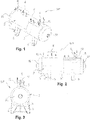
- Figs. 1-7 show a preferred embodiment of a reservoir 501 of a flash separator 500 according to the invention for the treatment of a fluid mixture containing liquefied methane and carbon dioxide.
- the flash separator 500 is used in preferred, although not exclusive manner, in a plant for the production of liquefied biomethane or liquefied natural gas, diagrammatically shown in Figs. 11 and 12 and described in greater detail below, to purify or enrich in methane a fluid mixture originating from a liquefaction unit.
- the flash separator 500 further comprises a pressure reducing device 502 installed in a reservoir supply line 501, diagrammatically shown in Figs. 11 and 12 .
- the pressure reducing device 502 can be, for example, a pressure reducing valve or a lamination valve, and is in any case of known type and therefore will not be described in greater detail here.
- the reservoir 501 is a cylindrical reservoir with a horizontal working position.
- terms or expressions indicating or implying a given spatial position in relative terms such as, for example, lower or below, upper or above, laterally adjacent, top, bottom, are to be understood with reference to such an operative position.
- the reservoir 501 has a double-shell structure, with an inner shell 1, which delimits an inner chamber 2 of reservoir 501, and an outer shell 3, which encloses the inner shell 1, forming a cavity 4 therewith.
- the inner shell 1 and the outer shell 3 have preferably a similar structure, comprising a central cylindrical body, respectively 11 or 31, closed at the ends of the head by a pair of caps, respectively 12 or 32, which may be pseudo-elliptical, decinormal, torospherical or spherical.
- the cavity 4 is preferably filled with thermally insulating material (not shown).
- the thermally insulating material is a pourable incoherent material, e.g. perlite or other similar thermally insulating mineral-based material.
- a vacuum can also be created therein.
- the reservoir 501 is equipped with individual or interconnected support elements to form a support frame to support the reservoir 501 in its horizontal operating position.
- support legs 5 there are four support legs 5, respectively two of which are visible in each of the views of Figs. 1-3 .
- the reservoir 501 comprises a mixture inlet 6, to introduce a fluid mixture to be treated into the inner chamber 2, comprising liquefied methane and carbon dioxide, after this mixture has passed through the pressure reducing device 502.
- the mixture inlet 6 is preferably arranged in a portion of the reservoir top 501, at one of its longitudinal ends.
- the reservoir 501 thus comprises a liquid phase outlet 7, to extract a separate liquid phase, enriched with methane, from the inner chamber 2.
- the liquid phase outlet 7 is preferably arranged in a portion of the bottom of the reservoir 501, at another longitudinal end, opposite to the one at which the mixture inlet 6 is located.
- the reservoir 501 further comprises a gas phase outlet 20, to extract a separated gas fraction, containing more volatile substances and any other non-condensable substances present in the mixture, which separate from it following the expansion resulting from the pressure reduction obtained through the pressure reducer device 502, from the inner chamber 2.
- the gas phase outlet 20 is preferably arranged in a portion of the top of the reservoir 501, at its longitudinal end, opposite to the one at which the mixture inlet 6 is located.
- accesses 8, 9 for measuring and controlling instruments for the inner chamber 2.
- the accesses 8, 9 are also preferably arranged in a portion of the top of the reservoir 501 and distributed longitudinally along the latter, aligned between them and/or staggered angularly in a circumferential direction.
- the reservoir 501 further comprises an access 10 to the cavity 4, obtained in the outer shell 3, preferably in the top thereof at one longitudinal end, for installing measuring and monitoring instruments of the cavity 4 itself.
- connection assemblies of the type known for connecting the reservoir 501 to corresponding outer instrumentation lines.
- the exact configuration of such connection units depends on the specific installation conditions for the reservoir 501.
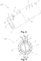
- Figs. 4-7 the same elements are instead shown without connection assemblies, as simple tubular sections.
- the dividing walls 13 and 14 are formed by plates with a circular segment shape and a diameter equal to an inner diameter of the cylindrical body 11 of the inner shell 1, and are both arranged in the cylindrical body 11 perpendicular to the longitudinal axis X-X thereof, and therefore parallel to each other.
- the partition walls 13, 14 do not completely occupy the cross section of the cylindrical body 11 but only a portion thereof.
- the first partition wall 13 may have a total surface area, including the surface area of openings made therein, preferably equal to about 90% of the surface area of the transverse section of the cylindrical body 11.
- the second partition wall 14 may have a smaller total surface area, preferably about 70% of the surface area of the cross section of the cylindrical body 11.
- the partition walls 13, 14 have preferably straight, free edges 15, 16 at the top.
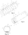
- the free edge 15 of the first partition wall 13, with a larger surface area, is at a height h1 greater than a height h2 of the free edge 16 of the second partition wall 14, which has a smaller surface area ( Fig. 6 ).
- the first dividing wall 13 divides the inner chamber 2 into two regions A, B, which are mutually adjacent side-by-side.
- the second partition wall 14 divides region B into two sub-regions B1, B2, in which sub-region B1 is laterally adjacent to region A and sub-region B2 is laterally adjacent to sub-region B1, on one side of the latter opposite to region A.
- the mixture inlet 6 is located in region A, while the liquid phase outlet 7 is located in sub-region B2, further away with respect to region A.
- Region A is in fluid communication with region B, more precisely with sub-region B1, through a number of openings17 in the first partition wall 13.
- the openings 17 are preferably configured as mutually parallel, preferably horizontal slits.
- the openings 17 are in particular located in a lower zone of the first partition wall 13, e.g. in a lower fifth or sixth thereof (see Fig. 10 ).
- the first sub-region B1 is, in turn, in fluid communication with the second sub-region B2 via an overflow port 18 defined between the second partition wall 14, in particular, its free edge 16, and a wall of the inner shell 1, in particular of its top.
- the first region A there is preferably a level sensor (not shown in the figures) to monitor the liquid level in that region. As shown in greater detail below, in relation to the operation of the reservoir 501, such a parameter is used to control the discontinuous operation of the flash separator 500.
- the first region A and the first sub-region B1 each preferably occupy a relatively small volume compared to the total volume of the inner chamber 2.
- the first region A may have a volume preferably equal to about 16% of the total volume of the inner chamber 2
- the first sub-region B1 may have a volume preferably equal to about 10% of the total volume of the invention.
- the reservoir 501 further comprises a cooling duct 19 extending in the cavity 4, through which it is possible to circulate the gas fraction separated and extracted from the inner chamber 2, which is still relatively cold, thus actively contributing to the thermal insulation of the reservoir 501, in the cavity 4.
- the cooling duct 19 preferably extends as a spiral around the inner shell 1 and is preferably anchored to the outer surface thereof.
- a first end 21 of the cooling duct 19 is connected to the gas phase outlet 20 described above, while a second end 22 of the cooling duct 19 is conducted out of the cavity 4, through the outer shell 3, at the longitudinal end of reservoir 501 where the mixture inlet 6 is located.
- the cooling duct 9 is passed through the gas phase in countercurrent with respect to the liquid phase flow in the inner chamber 2.
- the second end 22 of the cooling duct 19 is shown provided with a respective connection assembly of the type known for connecting to a corresponding outer line.
- the second end 22 of the cooling duct 19 is shown without connection assembly, as a simple tubular section.
- a fluid mixture containing liquefied methane and carbon dioxide after passing through the pressure reducing device 502, enters the reservoir 501, more precisely into region A of the inner chamber 2, by means of the mixture inlet 6.
- the fluid mixture undergoes an instantaneous expansion, with partial evaporation (flash evaporation) of the most volatile fraction of the fluid mixture, which begins to separate from the liquid phase.
- the gas phase which separates from the fluid mixture migrates freely towards and along the top of inner chamber 2 until it reaches the gas phase outlet 20 present there.
- the pressure reduction obtained by the pressure reducer device 502 also determines a decrease in the temperature that takes the fluid mixture to over-saturation condition, with consequent formation of carbon dioxide crystals and of water still present, which tend to deposit by gravity at the bottom of the inner chamber 2.
- the solid phase which separates from the fluid mixture remains confined to the first region A of inner chamber 2, while the liquid phase, enriched in methane, can pass into the adjacent sub-region B1 of inner chamber 2 through the openings 17 present in the lower zone of the first partition wall 13.
- the liquid phase accumulates in sub-region B1 until it reaches the upper free edge 16 of the second partition wall 14 and then overflows freely through the overflow port 18 into the adjacent sub-region B2.
- the liquid phase runs substantially along the bottom of the inner chamber 2 until it reaches the liquid phase outlet 7, through which it is discharged from the reservoir 501.
- the continuous operation of the flash separator 500 results in a progressive accumulation of the solid phase consisting of carbon dioxide ice crystals and water at the bottom of the inner chamber 2 in the region A. This makes it progressively more difficult for the liquid phase to pass towards sub-region B1 through the openings 17 in the first partition wall 13, so that during full operation of the flash separator 500 the level of liquid in region A, monitored by the specially designed level sensor, tends to progressively increase.
- the operation of the flash separator 500 is interrupted when the liquid level in region A exceeds a set level. As better explained below, this can be achieved by temporarily stopping the plant in which the flash separator 500 is used, or, where possible, more preferably temporarily excluding the flash separator 500 from a production line of the plant itself.
- the stopping of the flash separator 500 naturally causes an increase in temperature inside the reservoir 501, as a result of which the carbon dioxide and any water accumulated in solid form in the inner chamber 2, particularly in region A, evaporate and escape from the inner chamber 2 through the gas phase outlet 20.
- the solid phase which has separated from the fluid mixture to be treated and has accumulated inside the reservoir 501 during an operating cycle of the flash separator 500 can thus be eliminated from the reservoir 501 automatically and passively as gas phase, without needing to provide a special discharge system.
- the flash separator 500 can be put back into operation, restarting the plant in which it is used, if it had previously been stopped, or reconnecting it to a production line of the plant.
- Figs. 11 and 12 schematically show two preferred embodiments of a plant according to the invention for the production of biomethane or liquefied natural gas, which exploits the flash separator 500 described above.
- the plant shown is particularly suited for the production of liquefied biomethane from biogas from anaerobic digestion of organic residues or from landfills.
- the plant can receive at the inlet, at an inlet 100, a flow of a crude fluid mixture, essentially gaseous, containing methane and other substances, typically carbon dioxide, water vapor, oxygen, hydrogen, nitrogen and/or compounds thereof, at a pressure from 0.9 bar to 20 bar and at a substantially ambient temperature.
- a crude fluid mixture typically carbon dioxide, water vapor, oxygen, hydrogen, nitrogen and/or compounds thereof
- a conventional compression unit 200 by means of which the pressure of the crude fluid mixture is increased to process levels, if necessary, from 15 bar to 20 bar, is provided downstream of the inlet 100.
- a treatment unit 300 in which the crude fluid mixture is purified, eliminating to a large extent from it the typically present contaminants, in particular, carbon dioxide, water vapor, oxygen, hydrogen, nitrogen and/or compounds thereof, sulfur and/or compounds thereof, is provided downstream of the compression unit 200.
- the treatment unit 300 comprises, in succession, a pair of membrane separators 301, 302 and a TSA (Temperature Swing Adsorption) separator 303, e.g. four columns.
- TSA Tempoture Swing Adsorption
- the gas contaminant substances separated from the crude fluid mixture in the treatment unit 300, in particular in the membrane separators 301, 302, are sent to a gas phase outlet 700 of the plant by means of a corresponding gas phase discharge line 701, and can be taken there for further treatment, e.g. for the recovery of carbon dioxide and/or hydrogen, or for final disposal by burning.
- the purified fluid mixture leaving the treatment unit 300 has methane concentrations of 93.5% to 99% by volume, compatible with a subsequent liquefaction process.
- a liquefaction unit 400 by means of which the purified fluid mixture is liquefied, is provided downstream of the treatment unit 300.
- the liquefaction unit 400 comprises a regenerative exchanger 401, in which the purified fluid mixture is precooled by means of heat exchange with the relatively cold gas phase, discharged from a flash separator 500 downstream of the liquefaction unit 400, and a liquefactor 402, e.g. operating according to a Stirling cycle.
- the liquefaction unit 400 is operated so as to obtain a liquid liquefied mixture therefrom, preferably under saturation conditions at a temperature of -125°C and a pressure of 13 bar.
- a liquid liquefied mixture therefrom, preferably under saturation conditions at a temperature of -125°C and a pressure of 13 bar.
- residual fractions of non-condensable compounds, as well as of carbon dioxide and possibly liquefied water are typically still present.
- the liquefied fluid mixture leaving the liquefaction unit 400 is sent to a flash separator 500 of the type described above, comprising the reservoir 501 and the pressure reducer device 502.
- a flash separator 500 of the type described above, comprising the reservoir 501 and the pressure reducer device 502.
- Substantially pure biomethane or liquefied natural gas (concentrations of methane equal to 98-99% in volume) is obtained at the outlet of the flash separator 500, at a pressure between about 2 bar and about 4 bar and a temperature of about -140 °C, which is sent to a corresponding outlet 600 of the plant, from where it can be taken for storage or transport.
- the gas phase extracted from the reservoir 501 of the flash separator 500 is sent to the regenerative exchanger 401 of the liquefaction unit 400 and then to the gas phase discharge line 701 of the plant.
- the embodiment of the system shown in Fig. 12 differs from that shown in Fig. 11 only for the presence of two flash separators 500a, 500b of the type described above, comprising respective reservoirs 501a, 501b and pressure reducer devices 502a, 502b.
- the flash separators 500a, 500b are arranged in parallel and can be selectively inserted into the line coming from the liquefaction unit 400, e.g. by means of a three-way valve 800, or, in embodiments not shown, by means of two gate valves positioned in the respective branches of supply of the two flash separators 500a, 500b.
- the two flash separators 500a, 500b are mutually the same and are operated in alternating manner.
- the flow of the liquefied fluid mixture coming from the liquefaction unit 400 is diverted through the three-way valve 800 to the other flash separator, and vice versa. This ensures continuous operation of the system, eliminating downtime that would be required to allow periodic removal of the solid phase from a single flash separator.
Landscapes
- Engineering & Computer Science (AREA)
- Physics & Mathematics (AREA)
- Mechanical Engineering (AREA)
- Thermal Sciences (AREA)
- General Engineering & Computer Science (AREA)
- Chemical & Material Sciences (AREA)
- Chemical Kinetics & Catalysis (AREA)
- Oil, Petroleum & Natural Gas (AREA)
- General Chemical & Material Sciences (AREA)
- Organic Chemistry (AREA)
- Organic Low-Molecular-Weight Compounds And Preparation Thereof (AREA)
- Carbon And Carbon Compounds (AREA)
Applications Claiming Priority (1)
| Application Number | Priority Date | Filing Date | Title |
|---|---|---|---|
| IT201800008921 | 2018-09-26 |
Publications (2)
| Publication Number | Publication Date |
|---|---|
| EP3628951A1 true EP3628951A1 (fr) | 2020-04-01 |
| EP3628951B1 EP3628951B1 (fr) | 2023-06-28 |
Family
ID=64607183
Family Applications (1)
| Application Number | Title | Priority Date | Filing Date |
|---|---|---|---|
| EP19199177.7A Active EP3628951B1 (fr) | 2018-09-26 | 2019-09-24 | Séparateur flash pour le traitement d'un mélange liquide contenant du méthane liquéfié et du dioxyde de carbone de gaz et installation de production de biométhane ou de gaz naturel liquéfié comprenant un tel séparateur flash |
Country Status (2)
| Country | Link |
|---|---|
| EP (1) | EP3628951B1 (fr) |
| ES (1) | ES2954384T3 (fr) |
Cited By (2)
| Publication number | Priority date | Publication date | Assignee | Title |
|---|---|---|---|---|
| WO2023180391A1 (fr) * | 2022-03-23 | 2023-09-28 | Engie | Procédé de liquéfaction d'un gaz d'alimentation riche en méthane, et installation correspondante |
| CN118882289A (zh) * | 2024-09-29 | 2024-11-01 | 浙江盛洋气体设备制造有限公司 | 一种用于气体分离提纯的深冷空分装置 |
Citations (6)
| Publication number | Priority date | Publication date | Assignee | Title |
|---|---|---|---|---|
| WO2010141996A1 (fr) * | 2009-06-12 | 2010-12-16 | Cool Energy Limited | Dispositif et procédé pour séparer un gaz acide en gaz adouci et liquide acide |
| WO2011002277A1 (fr) * | 2009-07-01 | 2011-01-06 | Twister B.V. | Procédé d'élimination du dioxyde de carbone présent dans un flux de fluide et ensemble séparateur pour fluides |
| US20130340475A1 (en) * | 2012-06-20 | 2013-12-26 | Battelle Energy Alliance, Llc | Natural gas liquefaction employing independent refrigerant path |
| US20150316333A1 (en) * | 2014-05-01 | 2015-11-05 | Conocophillips Company | Liquid drains in core-in-shell heat exchanger |
| WO2016126159A2 (fr) | 2015-02-03 | 2016-08-11 | Ilng B.V. | Système et procédé de traitement d'un fluide comprenant des hydrocarbures |
| US20180023891A1 (en) * | 2014-10-23 | 2018-01-25 | Petroliam Nasional Berhad (Petronas) | Methods and apparatus for mechanical separation of co2 |
-
2019
- 2019-09-24 ES ES19199177T patent/ES2954384T3/es active Active
- 2019-09-24 EP EP19199177.7A patent/EP3628951B1/fr active Active
Patent Citations (6)
| Publication number | Priority date | Publication date | Assignee | Title |
|---|---|---|---|---|
| WO2010141996A1 (fr) * | 2009-06-12 | 2010-12-16 | Cool Energy Limited | Dispositif et procédé pour séparer un gaz acide en gaz adouci et liquide acide |
| WO2011002277A1 (fr) * | 2009-07-01 | 2011-01-06 | Twister B.V. | Procédé d'élimination du dioxyde de carbone présent dans un flux de fluide et ensemble séparateur pour fluides |
| US20130340475A1 (en) * | 2012-06-20 | 2013-12-26 | Battelle Energy Alliance, Llc | Natural gas liquefaction employing independent refrigerant path |
| US20150316333A1 (en) * | 2014-05-01 | 2015-11-05 | Conocophillips Company | Liquid drains in core-in-shell heat exchanger |
| US20180023891A1 (en) * | 2014-10-23 | 2018-01-25 | Petroliam Nasional Berhad (Petronas) | Methods and apparatus for mechanical separation of co2 |
| WO2016126159A2 (fr) | 2015-02-03 | 2016-08-11 | Ilng B.V. | Système et procédé de traitement d'un fluide comprenant des hydrocarbures |
Cited By (3)
| Publication number | Priority date | Publication date | Assignee | Title |
|---|---|---|---|---|
| WO2023180391A1 (fr) * | 2022-03-23 | 2023-09-28 | Engie | Procédé de liquéfaction d'un gaz d'alimentation riche en méthane, et installation correspondante |
| FR3133908A1 (fr) * | 2022-03-23 | 2023-09-29 | Engie | Procédé de liquéfaction d’un gaz d’alimentation riche en méthane, et installation correspondante |
| CN118882289A (zh) * | 2024-09-29 | 2024-11-01 | 浙江盛洋气体设备制造有限公司 | 一种用于气体分离提纯的深冷空分装置 |
Also Published As
| Publication number | Publication date |
|---|---|
| ES2954384T3 (es) | 2023-11-21 |
| EP3628951B1 (fr) | 2023-06-28 |
Similar Documents
| Publication | Publication Date | Title |
|---|---|---|
| CA2857122C (fr) | Procede de separation du dioxyde de carbone de courants de gaz d'acide liquide | |
| US20230384027A1 (en) | Process for cryogenic separation of a feed stream containing methane and air gases, facility for producing biomethane by purification of biogases derived from non-hazardous waste storage facilities (nhwsf) implementing the process | |
| US9718618B2 (en) | System and method for treating hydrogen to be stored in a salt cavern and supplying therefrom | |
| CN108138599B (zh) | 基于卡林那循环的气体加工装置废热至电力的转换 | |
| DK176585B1 (da) | Fremgangsmåde til stripning af en gas ved afköling i nærvær af methanol | |
| US20060248921A1 (en) | Landfill gas purification and liquefaction process | |
| EP3625196B1 (fr) | Procédé de récupération d'un courant d'hydrocarbures en c2+ dans un gaz résiduel de raffinerie et installation associée | |
| RU2501593C2 (ru) | Очистка потока газа | |
| EP3628951B1 (fr) | Séparateur flash pour le traitement d'un mélange liquide contenant du méthane liquéfié et du dioxyde de carbone de gaz et installation de production de biométhane ou de gaz naturel liquéfié comprenant un tel séparateur flash | |
| CN108138596A (zh) | 基于改进的高斯瓦米循环的具有灵活性的气体加工装置废热至电力和冷却的转换 | |
| EP1931612A1 (fr) | Procédé et appareil pour la purification de flux gazeux riches en méthane | |
| EP3254038B1 (fr) | Système et procédé de traitement d'un fluide comprenant des hydrocarbures | |
| CN105080278A (zh) | 油气回收方法 | |
| CA2801228A1 (fr) | Procede et appareil pour la purification de dioxyde de carbone a l'aide de dioxyde de carbone liquide | |
| CN205501233U (zh) | 天然气脱水脱重烃集成设备 | |
| KR20170107271A (ko) | 이산화탄소 액화 회수장치 | |
| CN103256786A (zh) | 抑燃抑爆型低浓度煤层气深冷液化装置 | |
| EP2476477B1 (fr) | Procédé de séchage d'un flux de gaz humide riche en co2 pour un procédé d'oxy-combustion | |
| WO2016076755A1 (fr) | Procédé de traitement de gaz naturel et dispositif de mise en œuvre | |
| JP7339929B2 (ja) | 空気分離装置、酸素および/または窒素の製造方法 | |
| US8857212B2 (en) | Process for the separation of contaminant or mixture of contaminants from a CH4-comprising gaseous feed stream | |
| CN108043062B (zh) | 一种储罐呼吸排放挥发性气体的处理系统 | |
| US10905996B2 (en) | Systems and methods to manage heat in an integrated oil and gas processing plant with sour gas injection | |
| EP3456810B1 (fr) | Installation et procédé de valorisation de biogaz | |
| CN220861050U (zh) | 二氧化碳提纯系统 |
Legal Events
| Date | Code | Title | Description |
|---|---|---|---|
| PUAI | Public reference made under article 153(3) epc to a published international application that has entered the european phase |
Free format text: ORIGINAL CODE: 0009012 |
|
| STAA | Information on the status of an ep patent application or granted ep patent |
Free format text: STATUS: THE APPLICATION HAS BEEN PUBLISHED |
|
| AK | Designated contracting states |
Kind code of ref document: A1 Designated state(s): AL AT BE BG CH CY CZ DE DK EE ES FI FR GB GR HR HU IE IS IT LI LT LU LV MC MK MT NL NO PL PT RO RS SE SI SK SM TR |
|
| AX | Request for extension of the european patent |
Extension state: BA ME |
|
| STAA | Information on the status of an ep patent application or granted ep patent |
Free format text: STATUS: REQUEST FOR EXAMINATION WAS MADE |
|
| 17P | Request for examination filed |
Effective date: 20200930 |
|
| RBV | Designated contracting states (corrected) |
Designated state(s): AL AT BE BG CH CY CZ DE DK EE ES FI FR GB GR HR HU IE IS IT LI LT LU LV MC MK MT NL NO PL PT RO RS SE SI SK SM TR |
|
| RIC1 | Information provided on ipc code assigned before grant |
Ipc: F25J 1/00 20060101ALI20221116BHEP Ipc: F25J 1/02 20060101ALI20221116BHEP Ipc: C10L 3/10 20060101ALI20221116BHEP Ipc: B01D 53/00 20060101ALI20221116BHEP Ipc: F25J 3/06 20060101AFI20221116BHEP |
|
| GRAP | Despatch of communication of intention to grant a patent |
Free format text: ORIGINAL CODE: EPIDOSNIGR1 |
|
| STAA | Information on the status of an ep patent application or granted ep patent |
Free format text: STATUS: GRANT OF PATENT IS INTENDED |
|
| INTG | Intention to grant announced |
Effective date: 20230119 |
|
| RIN1 | Information on inventor provided before grant (corrected) |
Inventor name: IELPO, GAETANO Inventor name: MARCHISIO, LUIGI Inventor name: FARINA, CORRADO Inventor name: SALDIVIA, ANDRES Inventor name: SOLARO, SIMONE Inventor name: ANTONINI, MASSIMILIANO |
|
| GRAS | Grant fee paid |
Free format text: ORIGINAL CODE: EPIDOSNIGR3 |
|
| GRAA | (expected) grant |
Free format text: ORIGINAL CODE: 0009210 |
|
| STAA | Information on the status of an ep patent application or granted ep patent |
Free format text: STATUS: THE PATENT HAS BEEN GRANTED |
|
| AK | Designated contracting states |
Kind code of ref document: B1 Designated state(s): AL AT BE BG CH CY CZ DE DK EE ES FI FR GB GR HR HU IE IS IT LI LT LU LV MC MK MT NL NO PL PT RO RS SE SI SK SM TR |
|
| REG | Reference to a national code |
Ref country code: CH Ref legal event code: EP |
|
| P01 | Opt-out of the competence of the unified patent court (upc) registered |
Effective date: 20230525 |
|
| REG | Reference to a national code |
Ref country code: AT Ref legal event code: REF Ref document number: 1583025 Country of ref document: AT Kind code of ref document: T Effective date: 20230715 |
|
| REG | Reference to a national code |
Ref country code: IE Ref legal event code: FG4D |
|
| REG | Reference to a national code |
Ref country code: DE Ref legal event code: R096 Ref document number: 602019031611 Country of ref document: DE |
|
| REG | Reference to a national code |
Ref country code: NL Ref legal event code: FP |
|
| REG | Reference to a national code |
Ref country code: SE Ref legal event code: TRGR Ref country code: LT Ref legal event code: MG9D |
|
| REG | Reference to a national code |
Ref country code: NO Ref legal event code: T2 Effective date: 20230628 |
|
| REG | Reference to a national code |
Ref country code: AT Ref legal event code: MK05 Ref document number: 1583025 Country of ref document: AT Kind code of ref document: T Effective date: 20230628 |
|
| REG | Reference to a national code |
Ref country code: ES Ref legal event code: FG2A Ref document number: 2954384 Country of ref document: ES Kind code of ref document: T3 Effective date: 20231121 |
|
| PG25 | Lapsed in a contracting state [announced via postgrant information from national office to epo] |
Ref country code: RS Free format text: LAPSE BECAUSE OF FAILURE TO SUBMIT A TRANSLATION OF THE DESCRIPTION OR TO PAY THE FEE WITHIN THE PRESCRIBED TIME-LIMIT Effective date: 20230628 Ref country code: LV Free format text: LAPSE BECAUSE OF FAILURE TO SUBMIT A TRANSLATION OF THE DESCRIPTION OR TO PAY THE FEE WITHIN THE PRESCRIBED TIME-LIMIT Effective date: 20230628 Ref country code: LT Free format text: LAPSE BECAUSE OF FAILURE TO SUBMIT A TRANSLATION OF THE DESCRIPTION OR TO PAY THE FEE WITHIN THE PRESCRIBED TIME-LIMIT Effective date: 20230628 Ref country code: HR Free format text: LAPSE BECAUSE OF FAILURE TO SUBMIT A TRANSLATION OF THE DESCRIPTION OR TO PAY THE FEE WITHIN THE PRESCRIBED TIME-LIMIT Effective date: 20230628 Ref country code: GR Free format text: LAPSE BECAUSE OF FAILURE TO SUBMIT A TRANSLATION OF THE DESCRIPTION OR TO PAY THE FEE WITHIN THE PRESCRIBED TIME-LIMIT Effective date: 20230929 |
|
| PG25 | Lapsed in a contracting state [announced via postgrant information from national office to epo] |
Ref country code: FI Free format text: LAPSE BECAUSE OF FAILURE TO SUBMIT A TRANSLATION OF THE DESCRIPTION OR TO PAY THE FEE WITHIN THE PRESCRIBED TIME-LIMIT Effective date: 20230628 |
|
| PG25 | Lapsed in a contracting state [announced via postgrant information from national office to epo] |
Ref country code: SK Free format text: LAPSE BECAUSE OF FAILURE TO SUBMIT A TRANSLATION OF THE DESCRIPTION OR TO PAY THE FEE WITHIN THE PRESCRIBED TIME-LIMIT Effective date: 20230628 |
|
| PG25 | Lapsed in a contracting state [announced via postgrant information from national office to epo] |
Ref country code: IS Free format text: LAPSE BECAUSE OF FAILURE TO SUBMIT A TRANSLATION OF THE DESCRIPTION OR TO PAY THE FEE WITHIN THE PRESCRIBED TIME-LIMIT Effective date: 20231028 |
|
| PG25 | Lapsed in a contracting state [announced via postgrant information from national office to epo] |
Ref country code: SM Free format text: LAPSE BECAUSE OF FAILURE TO SUBMIT A TRANSLATION OF THE DESCRIPTION OR TO PAY THE FEE WITHIN THE PRESCRIBED TIME-LIMIT Effective date: 20230628 Ref country code: SK Free format text: LAPSE BECAUSE OF FAILURE TO SUBMIT A TRANSLATION OF THE DESCRIPTION OR TO PAY THE FEE WITHIN THE PRESCRIBED TIME-LIMIT Effective date: 20230628 Ref country code: RO Free format text: LAPSE BECAUSE OF FAILURE TO SUBMIT A TRANSLATION OF THE DESCRIPTION OR TO PAY THE FEE WITHIN THE PRESCRIBED TIME-LIMIT Effective date: 20230628 Ref country code: PT Free format text: LAPSE BECAUSE OF FAILURE TO SUBMIT A TRANSLATION OF THE DESCRIPTION OR TO PAY THE FEE WITHIN THE PRESCRIBED TIME-LIMIT Effective date: 20231030 Ref country code: IS Free format text: LAPSE BECAUSE OF FAILURE TO SUBMIT A TRANSLATION OF THE DESCRIPTION OR TO PAY THE FEE WITHIN THE PRESCRIBED TIME-LIMIT Effective date: 20231028 Ref country code: EE Free format text: LAPSE BECAUSE OF FAILURE TO SUBMIT A TRANSLATION OF THE DESCRIPTION OR TO PAY THE FEE WITHIN THE PRESCRIBED TIME-LIMIT Effective date: 20230628 Ref country code: CZ Free format text: LAPSE BECAUSE OF FAILURE TO SUBMIT A TRANSLATION OF THE DESCRIPTION OR TO PAY THE FEE WITHIN THE PRESCRIBED TIME-LIMIT Effective date: 20230628 Ref country code: AT Free format text: LAPSE BECAUSE OF FAILURE TO SUBMIT A TRANSLATION OF THE DESCRIPTION OR TO PAY THE FEE WITHIN THE PRESCRIBED TIME-LIMIT Effective date: 20230628 |
|
| PG25 | Lapsed in a contracting state [announced via postgrant information from national office to epo] |
Ref country code: PL Free format text: LAPSE BECAUSE OF FAILURE TO SUBMIT A TRANSLATION OF THE DESCRIPTION OR TO PAY THE FEE WITHIN THE PRESCRIBED TIME-LIMIT Effective date: 20230628 |
|
| REG | Reference to a national code |
Ref country code: DE Ref legal event code: R097 Ref document number: 602019031611 Country of ref document: DE |
|
| PG25 | Lapsed in a contracting state [announced via postgrant information from national office to epo] |
Ref country code: DK Free format text: LAPSE BECAUSE OF FAILURE TO SUBMIT A TRANSLATION OF THE DESCRIPTION OR TO PAY THE FEE WITHIN THE PRESCRIBED TIME-LIMIT Effective date: 20230628 |
|
| REG | Reference to a national code |
Ref country code: CH Ref legal event code: PL |
|
| PLBE | No opposition filed within time limit |
Free format text: ORIGINAL CODE: 0009261 |
|
| STAA | Information on the status of an ep patent application or granted ep patent |
Free format text: STATUS: NO OPPOSITION FILED WITHIN TIME LIMIT |
|
| PG25 | Lapsed in a contracting state [announced via postgrant information from national office to epo] |
Ref country code: LU Free format text: LAPSE BECAUSE OF NON-PAYMENT OF DUE FEES Effective date: 20230924 |
|
| REG | Reference to a national code |
Ref country code: BE Ref legal event code: MM Effective date: 20230930 |
|
| GBPC | Gb: european patent ceased through non-payment of renewal fee |
Effective date: 20230928 |
|
| PG25 | Lapsed in a contracting state [announced via postgrant information from national office to epo] |
Ref country code: LU Free format text: LAPSE BECAUSE OF NON-PAYMENT OF DUE FEES Effective date: 20230924 Ref country code: MC Free format text: LAPSE BECAUSE OF FAILURE TO SUBMIT A TRANSLATION OF THE DESCRIPTION OR TO PAY THE FEE WITHIN THE PRESCRIBED TIME-LIMIT Effective date: 20230628 |
|
| 26N | No opposition filed |
Effective date: 20240402 |
|
| REG | Reference to a national code |
Ref country code: IE Ref legal event code: MM4A |
|
| PG25 | Lapsed in a contracting state [announced via postgrant information from national office to epo] |
Ref country code: IE Free format text: LAPSE BECAUSE OF NON-PAYMENT OF DUE FEES Effective date: 20230924 |
|
| PG25 | Lapsed in a contracting state [announced via postgrant information from national office to epo] |
Ref country code: GB Free format text: LAPSE BECAUSE OF NON-PAYMENT OF DUE FEES Effective date: 20230928 |
|
| PG25 | Lapsed in a contracting state [announced via postgrant information from national office to epo] |
Ref country code: CH Free format text: LAPSE BECAUSE OF NON-PAYMENT OF DUE FEES Effective date: 20230930 |
|
| PG25 | Lapsed in a contracting state [announced via postgrant information from national office to epo] |
Ref country code: IE Free format text: LAPSE BECAUSE OF NON-PAYMENT OF DUE FEES Effective date: 20230924 Ref country code: GB Free format text: LAPSE BECAUSE OF NON-PAYMENT OF DUE FEES Effective date: 20230928 Ref country code: CH Free format text: LAPSE BECAUSE OF NON-PAYMENT OF DUE FEES Effective date: 20230930 Ref country code: SI Free format text: LAPSE BECAUSE OF FAILURE TO SUBMIT A TRANSLATION OF THE DESCRIPTION OR TO PAY THE FEE WITHIN THE PRESCRIBED TIME-LIMIT Effective date: 20230628 |
|
| PG25 | Lapsed in a contracting state [announced via postgrant information from national office to epo] |
Ref country code: BE Free format text: LAPSE BECAUSE OF NON-PAYMENT OF DUE FEES Effective date: 20230930 |
|
| PG25 | Lapsed in a contracting state [announced via postgrant information from national office to epo] |
Ref country code: BG Free format text: LAPSE BECAUSE OF FAILURE TO SUBMIT A TRANSLATION OF THE DESCRIPTION OR TO PAY THE FEE WITHIN THE PRESCRIBED TIME-LIMIT Effective date: 20230628 |
|
| PG25 | Lapsed in a contracting state [announced via postgrant information from national office to epo] |
Ref country code: BG Free format text: LAPSE BECAUSE OF FAILURE TO SUBMIT A TRANSLATION OF THE DESCRIPTION OR TO PAY THE FEE WITHIN THE PRESCRIBED TIME-LIMIT Effective date: 20230628 |
|
| REG | Reference to a national code |
Ref country code: DE Ref legal event code: R081 Ref document number: 602019031611 Country of ref document: DE Owner name: HYSYTECH S.R.L., IT Free format text: FORMER OWNER: HYSYTECH S.R.L., TORINO, IT |
|
| PG25 | Lapsed in a contracting state [announced via postgrant information from national office to epo] |
Ref country code: CY Free format text: LAPSE BECAUSE OF FAILURE TO SUBMIT A TRANSLATION OF THE DESCRIPTION OR TO PAY THE FEE WITHIN THE PRESCRIBED TIME-LIMIT; INVALID AB INITIO Effective date: 20190924 |
|
| PG25 | Lapsed in a contracting state [announced via postgrant information from national office to epo] |
Ref country code: HU Free format text: LAPSE BECAUSE OF FAILURE TO SUBMIT A TRANSLATION OF THE DESCRIPTION OR TO PAY THE FEE WITHIN THE PRESCRIBED TIME-LIMIT; INVALID AB INITIO Effective date: 20190924 |
|
| PGFP | Annual fee paid to national office [announced via postgrant information from national office to epo] |
Ref country code: IT Payment date: 20250926 Year of fee payment: 7 Ref country code: NL Payment date: 20250925 Year of fee payment: 7 |
|
| PGFP | Annual fee paid to national office [announced via postgrant information from national office to epo] |
Ref country code: FR Payment date: 20250925 Year of fee payment: 7 |
|
| PGFP | Annual fee paid to national office [announced via postgrant information from national office to epo] |
Ref country code: SE Payment date: 20250929 Year of fee payment: 7 |
|
| PG25 | Lapsed in a contracting state [announced via postgrant information from national office to epo] |
Ref country code: TR Free format text: LAPSE BECAUSE OF FAILURE TO SUBMIT A TRANSLATION OF THE DESCRIPTION OR TO PAY THE FEE WITHIN THE PRESCRIBED TIME-LIMIT Effective date: 20230628 |
|
| PGFP | Annual fee paid to national office [announced via postgrant information from national office to epo] |
Ref country code: DE Payment date: 20250930 Year of fee payment: 7 |
|
| PGFP | Annual fee paid to national office [announced via postgrant information from national office to epo] |
Ref country code: NO Payment date: 20251009 Year of fee payment: 7 |
|
| PGFP | Annual fee paid to national office [announced via postgrant information from national office to epo] |
Ref country code: ES Payment date: 20251029 Year of fee payment: 7 |