EP3629077A1 - Verbessertes verfahren zur herstellung einer komponente eines brillengestells - Google Patents
Verbessertes verfahren zur herstellung einer komponente eines brillengestells Download PDFInfo
- Publication number
- EP3629077A1 EP3629077A1 EP19198821.1A EP19198821A EP3629077A1 EP 3629077 A1 EP3629077 A1 EP 3629077A1 EP 19198821 A EP19198821 A EP 19198821A EP 3629077 A1 EP3629077 A1 EP 3629077A1
- Authority
- EP
- European Patent Office
- Prior art keywords
- wire
- component
- ring
- lens
- outer perimeter
- Prior art date
- Legal status (The legal status is an assumption and is not a legal conclusion. Google has not performed a legal analysis and makes no representation as to the accuracy of the status listed.)
- Withdrawn
Links
- 238000000034 method Methods 0.000 title claims abstract description 17
- 239000002184 metal Substances 0.000 claims abstract description 12
- 238000003466 welding Methods 0.000 claims abstract description 10
- 238000004519 manufacturing process Methods 0.000 claims description 5
- 229910003460 diamond Inorganic materials 0.000 claims description 2
- 239000010432 diamond Substances 0.000 claims description 2
- 238000005034 decoration Methods 0.000 abstract description 3
- 238000005452 bending Methods 0.000 description 3
- 238000003486 chemical etching Methods 0.000 description 2
- 238000003801 milling Methods 0.000 description 2
- 238000003672 processing method Methods 0.000 description 2
- 238000010008 shearing Methods 0.000 description 2
- 239000000853 adhesive Substances 0.000 description 1
- 238000004026 adhesive bonding Methods 0.000 description 1
- 230000001070 adhesive effect Effects 0.000 description 1
- 238000010276 construction Methods 0.000 description 1
- 238000005520 cutting process Methods 0.000 description 1
- 238000005516 engineering process Methods 0.000 description 1
- 230000004927 fusion Effects 0.000 description 1
- 239000011521 glass Substances 0.000 description 1
- 239000000463 material Substances 0.000 description 1
- 230000003287 optical effect Effects 0.000 description 1
Images
Classifications
-
- G—PHYSICS
- G02—OPTICS
- G02C—SPECTACLES; SUNGLASSES OR GOGGLES INSOFAR AS THEY HAVE THE SAME FEATURES AS SPECTACLES; CONTACT LENSES
- G02C1/00—Assemblies of lenses with bridges or browbars
- G02C1/10—Special mounting grooves in the rim or on the lens
-
- G—PHYSICS
- G02—OPTICS
- G02C—SPECTACLES; SUNGLASSES OR GOGGLES INSOFAR AS THEY HAVE THE SAME FEATURES AS SPECTACLES; CONTACT LENSES
- G02C5/00—Constructions of non-optical parts
- G02C5/14—Side-members
- G02C5/18—Side-members reinforced
-
- G—PHYSICS
- G02—OPTICS
- G02C—SPECTACLES; SUNGLASSES OR GOGGLES INSOFAR AS THEY HAVE THE SAME FEATURES AS SPECTACLES; CONTACT LENSES
- G02C1/00—Assemblies of lenses with bridges or browbars
- G02C1/06—Bridge or browbar secured to or integral with closed rigid rims for the lenses
-
- G—PHYSICS
- G02—OPTICS
- G02C—SPECTACLES; SUNGLASSES OR GOGGLES INSOFAR AS THEY HAVE THE SAME FEATURES AS SPECTACLES; CONTACT LENSES
- G02C1/00—Assemblies of lenses with bridges or browbars
- G02C1/06—Bridge or browbar secured to or integral with closed rigid rims for the lenses
- G02C1/08—Bridge or browbar secured to or integral with closed rigid rims for the lenses the rims being tranversely split and provided with securing means
-
- G—PHYSICS
- G02—OPTICS
- G02C—SPECTACLES; SUNGLASSES OR GOGGLES INSOFAR AS THEY HAVE THE SAME FEATURES AS SPECTACLES; CONTACT LENSES
- G02C2200/00—Generic mechanical aspects applicable to one or more of the groups G02C1/00 - G02C5/00 and G02C9/00 - G02C13/00 and their subgroups
- G02C2200/10—Frame or frame portions made from wire
-
- G—PHYSICS
- G02—OPTICS
- G02C—SPECTACLES; SUNGLASSES OR GOGGLES INSOFAR AS THEY HAVE THE SAME FEATURES AS SPECTACLES; CONTACT LENSES
- G02C5/00—Constructions of non-optical parts
- G02C5/008—Spectacles frames characterized by their material, material structure and material properties
Definitions
- the invention refers to an improved method for producing a metal component of a frame for eyeglasses, in particular for producing a frame for lens of eyeglasses.
- the component is the whole frame for eyeglasses or part of such frame as for example a front mask suitable to support one or two lenses and/or a lateral rod that can be articulated to the mask.
- the invention also refers to a component that can be manufactured with the method.
- spectacle frames It is known to produce spectacle frames through chemical etching (or photo-shearing) of a metal sheet. Or a laser beam is used for cutting the sheet.
- decorations are then applied to the frame, such as surface geometrical patterns, in bas-relief as well.
- Another object is to obtain a method for producing an aforesaid metallic component with a decoration.
- Another object is to obtain a method for producing an aforesaid component with improved structural strength.
- frame it is meant here the support that supports a transparent medium fixed thereto to keep it in a suitable position before the eyes.
- Eyeglasses are the optical instrument consisting of the frame and the associated transparent medium.
- a first aspect of the invention concerns a method for producing a metal component of a frame for eyeglasses, with the steps of
- the wire is laid along a portion of the outer perimeter of the component, and the wire is fixed, e.g. welded, to the outer perimeter at least at two points.
- the aforementioned wire can have many functions and advantages, e.g. to strengthen or stiffen the component structure, decorate the component structure, and/or dampen the impacts that occur on the external edge of the component (if the wire dents it can be replaced but the structure of the component it is applied to remains intact).
- the component comprises or consists of a temple rod or bar, wherein the application of the wire is made on an edge or perimeter of the temple rod or bar.
- the component comprises or consists of a ring to support a lens along the perimeter of the lens
- the method has the steps of laying the wire along a portion of the outer perimeter of the ring, and fixing, e.g. welding or gluing, the wire to said outer perimeter at least at two points.
- a groove is formed along said portion of the outer perimeter (e.g. of the ring), a groove which serves as a seat for the wire and in which the wire is laid.
- the groove seat for the wire has a depth such as to leave the wire protruding from the groove. In this way the wire protrudes from the external edge of the component and protects it better.
- the ring has an inner edge that surrounds a pass-through opening, seat of or for a lens.
- a second groove is made on said inner edge, opposite to the one where the wire is placed; this second groove serves as a seat for the lens.
- Said ring can be closed or opened.
- a closed ring is a metal ring without interruptions in his perimeter, while an open ring has at least one interruption in the perimeter, such as for instance a C or a U, and therefore has at least two free ends.
- said at least two points are made at the - or at least at - two free ends.
- a clamping element in correspondence with the - or of at least - two free ends of the ring a clamping element is fixed able to tighten the ring around the lens.
- the clamping element comprises or consists of two approachable threaded tubes which can approach each other by rotating a screw that connects them.
- the wire is a metal wire or a diamond wire.
- the welding step takes place by laser welding, TIG or material fusion.
- the wire is placed inside a furrow on the outer perimeter (or edge) of the frame, and preferably the wire is welded at two points.
- a second aspect of the invention concerns an object obtained through the method, of which it shares the advantages and the variants described herein.
- the object is a pair of metallic eyeglasses or metal component of a pair of glasses (e.g. a frame, a front mask or a temple rod).
- the metal frame component for eyeglasses comprises a wire laid and fixed, e.g. welded or glued, to a portion of outer perimeter of the component.
- the outer perimeter is defined as the edge of the component that is diametrically opposite the lens.
- the component comprises or consists of a ring to support a lens along the perimeter of the lens.
- the ring comprises a groove, which acts as a seat for the wire.
- the groove for the wire has a depth such as to leave the wire protruding from the groove.
- the ring has an inner edge that surrounds a pass-through opening seat for a lens, and comprises a second groove on said inner edge, opposite to the one where the wire is placed.
- This ring can be closed or opened.
- said at least two points are located at the - or at least at - two free ends.
- the ring in correspondence with the - or with at least - two free ends of the ring, the ring comprises a clamping element able to tighten the ring around the lens.
- the clamping element comprises or consists of two threaded tubes that can approach each other by turning a screw that connects them.
- the frame comprises a furrow on its outer perimeter (or edge) and the wire is placed inside the furrow, preferably the wire being welded at two points.
- a third aspect of the invention concerns the use of a wire laid and fixed, e.g. welded, to a portion of the outer perimeter of a pair of metallic eyeglasses or a metallic component of eyeglasses (e.g. a frame, a front mask or a side rod).
- This third aspect shares advantages and variants described for the method.
- furrow here indicates a depression or a channel present on the perimeter of the frame.
- the depression or channel is defined by a bottom and two side walls, the wire being placed between the two side walls.
- the furrow is formed on the edge of the frame which is diametrically opposite the lens.
- the furrow is formed on the edge of the frame which is diametrically opposite to the edge on which said second groove is formed
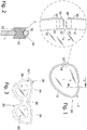
- the processing method is able to produce a component 10 as visible in fig. 1 . It is a metal ring 12 capable of supporting at the center a lens L.
- the outer perimeter of the ring 12 ( fig. 2 ) is furrowed by a groove 32 to receive the edge of the lens L.
- the groove 32 is obtained by internally milling the ring 12 or a bar from which it is obtained then by bending.
- the groove 32 is e.g. a flared channel and/or
- the processing method is able to equip the component 10 with a wire 30 arranged along its outer perimeter P.
- the outer perimeter P ( fig. 2 ) has a groove 34 for receiving snugly all or part of the wire 30.
- the groove 34 is obtained by milling externally the perimeter P or a rod from which the ring 12 is then obtained by bending.
- the groove 34 is e.g. a flared channel and/or
- the wire 30 is laid inside the groove 34 and then fixed to the ring 12 at least at two points. E.g. the wire 30 is fixed by welding.
- the wire 30 can be single and cover alone the whole perimeter P, completely surrounding the ring 12, in which case the wire 20 is preferably fixed to the ring 12 at two its ends which touch or almost touch ( fig. 2 ). Or the perimeter P is partially surrounded by a single wire 30, or the whole perimeter P is surrounded by wire but by two or more wires 30 arranged in tandem series.
- the ring 12 can have more than one structure. It can be closed, i.e. for example a circle or an oval or an ellipse without interruptions. Otherwise, a particular case of ring 12 is visible in fig. 1 , see also the zoomed view.
- the ring 12 is interrupted at a point K, so as to be slightly widened to facilitate the assembly of the lens L.
- two threaded tubes 22 are fixed, e.g. by welding, on the free and facing ends of the ring 12, and with a screw 24, which can be screwed into the tubes 22, the ends of the ring 12 are brought together to reduce the section of the ring 12 and tighten the lens L inside the groove 32.
- the ends of the wire 30 are preferably fixed in correspondence of the small tubes 22, for ease of construction and to hide the fixing points.
- two welding points 38 are shown as an example.
- the ring 12 can also be obtained by bending an extruded bar having cross-section visible in fig. 2 .
- Fig. 3 shows in plan view a second component of eyeglasses that can be produced with the method. It is a front-piece of eyeglasses, consisting of a single-piece metal flat mask 62 formed by two rings 64 connected by a bridge 68. Each ring 64 has a pass-through opening 66 in which to place a respective lens L. On the perimeter PP of the mask 62 the wire 30 is fixed, shown for sake of simplicity when detached and with dashed lines.
- the mask 62 can be produced e.g. by shearing from a sheet, by chemical etching or other.
- the groove 34 is then made on the mask 62 as described for the component 10, and the wire 30 is laid in the same way.
- the lens L can be fixed to the mask 62 e.g. with adhesive, screws or interlocking.
Landscapes
- Physics & Mathematics (AREA)
- Health & Medical Sciences (AREA)
- General Physics & Mathematics (AREA)
- Ophthalmology & Optometry (AREA)
- Optics & Photonics (AREA)
- Eyeglasses (AREA)
Applications Claiming Priority (1)
| Application Number | Priority Date | Filing Date | Title |
|---|---|---|---|
| IT201800008977 | 2018-09-27 |
Publications (1)
| Publication Number | Publication Date |
|---|---|
| EP3629077A1 true EP3629077A1 (de) | 2020-04-01 |
Family
ID=64607212
Family Applications (1)
| Application Number | Title | Priority Date | Filing Date |
|---|---|---|---|
| EP19198821.1A Withdrawn EP3629077A1 (de) | 2018-09-27 | 2019-09-21 | Verbessertes verfahren zur herstellung einer komponente eines brillengestells |
Country Status (1)
| Country | Link |
|---|---|
| EP (1) | EP3629077A1 (de) |
Citations (4)
| Publication number | Priority date | Publication date | Assignee | Title |
|---|---|---|---|---|
| DE3413827A1 (de) * | 1984-01-31 | 1985-08-01 | Mario 5503 Konz Hoffmann | Randlose brille |
| FR2580824A1 (fr) * | 1985-04-23 | 1986-10-24 | Claveau Jean Noel | Profile pour la realisation des cercles porte-verres des montures de lunettes du type a decor |
| FR2677465A1 (fr) * | 1991-06-10 | 1992-12-11 | Essilor Int | Monture de lunettes. |
| EP0937276B1 (de) * | 1996-11-05 | 2003-04-02 | FN Optik A/S | Brille |
-
2019
- 2019-09-21 EP EP19198821.1A patent/EP3629077A1/de not_active Withdrawn
Patent Citations (4)
| Publication number | Priority date | Publication date | Assignee | Title |
|---|---|---|---|---|
| DE3413827A1 (de) * | 1984-01-31 | 1985-08-01 | Mario 5503 Konz Hoffmann | Randlose brille |
| FR2580824A1 (fr) * | 1985-04-23 | 1986-10-24 | Claveau Jean Noel | Profile pour la realisation des cercles porte-verres des montures de lunettes du type a decor |
| FR2677465A1 (fr) * | 1991-06-10 | 1992-12-11 | Essilor Int | Monture de lunettes. |
| EP0937276B1 (de) * | 1996-11-05 | 2003-04-02 | FN Optik A/S | Brille |
Similar Documents
| Publication | Publication Date | Title |
|---|---|---|
| CN101373276B (zh) | 一种无框眼镜 | |
| JP3210661U (ja) | 近視用サングラス | |
| WO2009090733A1 (ja) | 鼻当てパッド無し眼鏡フレーム及びその眼鏡支持方法 | |
| EP1298482A2 (de) | Randlose Brille und zugehöriges Herstellungsverfahren | |
| KR101325465B1 (ko) | 교체형 안경 | |
| EP3629077A1 (de) | Verbessertes verfahren zur herstellung einer komponente eines brillengestells | |
| TWM455882U (zh) | 眼鏡框、邊緣以及掛腳 | |
| KR20180069234A (ko) | 조립식 안경 | |
| JPH0850263A (ja) | メガネ枠 | |
| JPH01274112A (ja) | メガネフレームに太陽光線面を着脱自在に固定する装置 | |
| FR2638247A1 (fr) | Dispositif pour la fabrication de lunettes sans monture, avec un entourage de protection des oculaires | |
| IT250277Y1 (it) | Famiglia di occhiali con montature di diverse ncurvature con astine intercambiabili | |
| JP6764008B1 (ja) | 眼鏡フレーム | |
| US6217169B1 (en) | Rimless or semi-rimless safety eyeglasses | |
| CN115053169B (zh) | 镜框与镜片结构 | |
| AU2017293435B2 (en) | Eyeglasses with easy snap-on lenses | |
| US2331666A (en) | Zylonite part for ophthalmic mountings | |
| KR200441972Y1 (ko) | 와이어 타입 안경테 | |
| US1151641A (en) | Goggles. | |
| JP3124890U (ja) | 眼鏡セット | |
| KR200231378Y1 (ko) | 안경조립용 나사 | |
| JP2011227376A (ja) | 前掛眼鏡 | |
| HK30034873A2 (en) | An eyewear product and a method of producing same | |
| US7731355B2 (en) | Eyeglass assembly | |
| JP2006119342A (ja) | メガネの作製方法 |
Legal Events
| Date | Code | Title | Description |
|---|---|---|---|
| PUAI | Public reference made under article 153(3) epc to a published international application that has entered the european phase |
Free format text: ORIGINAL CODE: 0009012 |
|
| STAA | Information on the status of an ep patent application or granted ep patent |
Free format text: STATUS: THE APPLICATION HAS BEEN PUBLISHED |
|
| AK | Designated contracting states |
Kind code of ref document: A1 Designated state(s): AL AT BE BG CH CY CZ DE DK EE ES FI FR GB GR HR HU IE IS IT LI LT LU LV MC MK MT NL NO PL PT RO RS SE SI SK SM TR |
|
| AX | Request for extension of the european patent |
Extension state: BA ME |
|
| STAA | Information on the status of an ep patent application or granted ep patent |
Free format text: STATUS: REQUEST FOR EXAMINATION WAS MADE |
|
| 17P | Request for examination filed |
Effective date: 20200928 |
|
| RBV | Designated contracting states (corrected) |
Designated state(s): AL AT BE BG CH CY CZ DE DK EE ES FI FR GB GR HR HU IE IS IT LI LT LU LV MC MK MT NL NO PL PT RO RS SE SI SK SM TR |
|
| P01 | Opt-out of the competence of the unified patent court (upc) registered |
Effective date: 20230515 |
|
| STAA | Information on the status of an ep patent application or granted ep patent |
Free format text: STATUS: EXAMINATION IS IN PROGRESS |
|
| 17Q | First examination report despatched |
Effective date: 20240402 |
|
| STAA | Information on the status of an ep patent application or granted ep patent |
Free format text: STATUS: THE APPLICATION IS DEEMED TO BE WITHDRAWN |
|
| 18D | Application deemed to be withdrawn |
Effective date: 20240803 |