EP3629171A1 - Schlossverwalter für multikernarchitekturen - Google Patents
Schlossverwalter für multikernarchitekturen Download PDFInfo
- Publication number
- EP3629171A1 EP3629171A1 EP19198447.5A EP19198447A EP3629171A1 EP 3629171 A1 EP3629171 A1 EP 3629171A1 EP 19198447 A EP19198447 A EP 19198447A EP 3629171 A1 EP3629171 A1 EP 3629171A1
- Authority
- EP
- European Patent Office
- Prior art keywords
- lock
- message
- manager
- managers
- mov
- Prior art date
- Legal status (The legal status is an assumption and is not a legal conclusion. Google has not performed a legal analysis and makes no representation as to the accuracy of the status listed.)
- Ceased
Links
Images


Classifications
-
- G—PHYSICS
- G06—COMPUTING OR CALCULATING; COUNTING
- G06F—ELECTRIC DIGITAL DATA PROCESSING
- G06F9/00—Arrangements for program control, e.g. control units
- G06F9/06—Arrangements for program control, e.g. control units using stored programs, i.e. using an internal store of processing equipment to receive or retain programs
- G06F9/46—Multiprogramming arrangements
- G06F9/52—Program synchronisation; Mutual exclusion, e.g. by means of semaphores
- G06F9/526—Mutual exclusion algorithms
-
- G—PHYSICS
- G06—COMPUTING OR CALCULATING; COUNTING
- G06F—ELECTRIC DIGITAL DATA PROCESSING
- G06F9/00—Arrangements for program control, e.g. control units
- G06F9/06—Arrangements for program control, e.g. control units using stored programs, i.e. using an internal store of processing equipment to receive or retain programs
- G06F9/44—Arrangements for executing specific programs
- G06F9/448—Execution paradigms, e.g. implementations of programming paradigms
- G06F9/4498—Finite state machines
-
- G—PHYSICS
- G06—COMPUTING OR CALCULATING; COUNTING
- G06F—ELECTRIC DIGITAL DATA PROCESSING
- G06F9/00—Arrangements for program control, e.g. control units
- G06F9/06—Arrangements for program control, e.g. control units using stored programs, i.e. using an internal store of processing equipment to receive or retain programs
- G06F9/46—Multiprogramming arrangements
- G06F9/52—Program synchronisation; Mutual exclusion, e.g. by means of semaphores
- G06F9/524—Deadlock detection or avoidance
-
- G—PHYSICS
- G06—COMPUTING OR CALCULATING; COUNTING
- G06F—ELECTRIC DIGITAL DATA PROCESSING
- G06F9/00—Arrangements for program control, e.g. control units
- G06F9/06—Arrangements for program control, e.g. control units using stored programs, i.e. using an internal store of processing equipment to receive or retain programs
- G06F9/46—Multiprogramming arrangements
- G06F9/54—Interprogram communication
- G06F9/542—Event management; Broadcasting; Multicasting; Notifications
Definitions
- the present disclosure relates generally to the field of multi-core computer architectures, and in particular to a circuit and method for managing locks.
- a lock or mutex is a synchronization mechanism that limits access to a resource, for example access to one or more addresses in a memory.
- Such locks are used when there are multiple threads of execution being executed in parallel based on shared data, risking an incorrect operation if mutual exclusion of memory accesses is not imposed.
- a lock ensures that a single, unique processing thread has access rights to the resource at a given time.
- a system is needed to manage the locks, including creating locks, and handling the requests from processors for ownership of a lock.
- the number of processors in a multi-core architecture increases, the complexity of handling the locks also increases. Indeed, in general, the greater the number of processors, the greater the number of tasks that will be executed in parallel, and the greater the number of locks that need to be generated and managed.
- communications between the processors or CPUs are generally performed via a network on chip (NoC) in which channels are provided between the processors.
- NoC network on chip
- the management of locks in a multi-core architecture increases the number of messages to be transmitted over the NoC, leading to an increase in the communications load, which can in turn lead to communications delays.
- Embodiments of the present disclosure address one or more needs in the prior art.
- a multi-core architecture comprising: a plurality of processing devices, each processing device comprising a single processor or a cluster of processors; and a lock manager associated with each processing device, each lock manager being configured to: store a first data value indicating of whether or not it currently owns a first lock, the first lock authorizing access to a resource; and permit an owner of the first lock to be determined by one or more lock managers by broadcasting, over an interconnection network to each of the other lock managers, at least one message.
- the message broadcast to each of the other lock managers is either: a message indicating that ownership of the first lock has or will move to another processing device; or a message requesting ownership of the first lock.
- each lock manager comprises a lock manager circuit comprising a logic circuit implementing a finite state machine.
- each lock manager further comprises a memory storing a table having an entry associated with the first lock, the entry including the first data value.
- each lock manager is partially implemented by one or more software modules providing an interface between a user application and the lock manager circuit.
- the interconnection network is a network-on-chip.
- the interconnection network is a 2D mesh implementing x-first message routing.
- the lock managers are configured to transmit messages to each other over the interconnection network on at least three separate channels.
- At least one of the plurality of processing devices is a cluster of two or more processors sharing one of said lock managers.
- each lock manager is configured to transmit over the interconnection network some or all of the following messages to one or more other lock managers: a lock initiation broadcast message; a lock initiation acknowledgement message; a lock deletion message; a lock request message or a lock request broadcast message; a lock request acknowledgement message acknowledging receipt of the lock request message; a lock move message indicating when a lock has or will be moved to another lock manager; a lock move acknowledgement message acknowledging receipt of the lock move message; a lock denied message indicating that a lock is in use and cannot be transferred; and a lock moved message indicating that responsibility for a lock has been entirely transferred from one lock manager to another lock manager.
- the lock managers are configured to store a distributed waiting list for lock ownership.
- a processing thread executed by a first of the processing devices is only permitted to modify a lock when it is owned by the lock manager associated with the first processing device.
- a method of lock management in a multi-core architecture comprising a plurality of processing devices, each processing device comprising a single processor or a cluster of processors, the method comprising: storing, by a lock manager associated with each processing device, a first data value indicating whether or not the lock manager currently owns a first lock, the first lock authorizing access to a resource; and broadcasting, by one lock manager over an interconnection network to each of the other lock managers, at least one message permitting a current owner of the first lock to be identified.
- the message broadcast to each of the other lock managers is either: a message indicating that ownership of the first lock has or will move to another processing device; or a message requesting ownership of the first lock.
- the method further comprises: initiating a new lock by a first of the lock managers; and broadcasting, by the first lock manager, a lock initiation message to each of the other lock managers informing them of the initiation of the new lock.
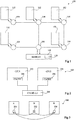
- FIG. 1 schematically illustrates a multi-core computer architecture 100 according to an example embodiment.
- the architecture 100 comprises processing devices 102, five being illustrated in the example of Figure 1 .
- Each processing device 102 may correspond to a single CPU or to a cluster of CPUs.
- Each processing device 102 is for example coupled to a corresponding node 104 of an interconnection network, which is for example an NoC.
- a further node 106 of the network is for example coupled to a memory (MEMORY) 108, which is for example accessible by all of the processing devices 102 via the NoC.
- MEMORY memory
- the NoC is for example a mesh network based on message routing.
- the nodes 104, 106 of the network are for example arranged in a 2D grid, interconnected by wired connections in x and y directions.
- Each node 104, 106 for example corresponds to a switch that is capable of temporarily storing messages, or subparts of messages known as flits, and routing them towards their destination.
- the transmission of messages across the network is for example performed using x-first routing, in other words messages are transmitted along the wired connections in the x-direction until they arrive in a column corresponding to their destination node, and they are then routed along the wired connections in the y-direction until they reach the destination node.
- the memory 108 is for example a random access memory, and comprises at least one shared portion 110 corresponding to one or more addresses to be protected using one or more locks.
- the shared portion 110 is shared by at least two, and in some cases all, of the processing devices 102.
- a lock also known as a mutex, is a property that can be assigned to any one of the processing devices 102 at a given time that allows only that processing device 102 to access and/or modify a portion of a memory.
- each lock corresponds to a single memory address, or to a range of memory addresses.
- a protocol is implemented that ensures that the lock can be owned by a single processing device 102 at any given time, thereby preventing simultaneous memory accesses that could lead to incorrect execution of one or more execution threads.
- the creation of a lock for a given memory address or memory address range is for example initiated by a software application running on one of the processing devices of the multi-core architecture.
- FIG. 2 schematically illustrates one of the processing devices 102 in more detail according to an example in which it corresponds to a cluster of processors.
- the device 102 comprises CPUs 202 (CPU1) and 204 (CPU2).
- Each CPU 202, 204 has a private local cache memory (CACHE) 206, and the CPUs of the cluster for example further share a level 2 cache memory (CACHE L2) 208.
- CACHE private local cache memory
- Figure 3 represents a system for managing locks that has been proposed. For example, a similar approach was proposed in the publication by Kuo, Carter and Kuramkote entitled “MP-LOCKs: Replacing Hardware Synchronization Primitives with Message Passing", Proceedings fifth international symposium on High-Computer Architectures, 9-13 Jan, 1999 .
- Figure 3 shows processors A and B, and a server M.
- the server M is responsible for creating locks, and Figure 3 shows the case in which a lock 302 is created.
- the lock may then be passed, upon request, to either of the processors A and B, as will now be described in more detail with reference to Figure 4 .
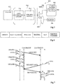
- Figure 4 is a diagram representing lock management communications in the architecture of Figure 3 .
- Solid vertical lines in Figure 4 represent the server M and the execution threads A and B of the processors A and B respectively.
- the dotted vertical lines represent memory zones LockBuf(M), LockBuf(A) and LockBuf(B), which are memory zones respectively associated with the server M and with the processors A and B and reserved for lock management.
- the server M creates a new lock (CREATE), and it is instantiated (c) in the local memory LockBuf(M) of the server M.
- the server M is the manager of this lock.
- the processing thread A wishes to take ownership (LOCK) of the lock, and makes a lock request (1) to its local memory LockBuf(A), but obtains a miss. It for example issues a request (REQUEST LOCK) to the server M.
- the request is processed at the software level, and as the lock is available (s), the lock is moved (MOVE LOCK) to the local memory of the processor A.
- the lock is thus physically located in this local memory LockBuf(A), and when the lock is subsequently released (u) by the processing thread A at a time t3 (UNLOCK), it remains physically in the local memory LockBuf(A).
- LOCK a hit is obtained from the local memory LockBuf(A), and the lock is directly obtained by the processing thread A.
- the processing thread B wishes to acquire the lock, and obtains a miss from its local memory LockBuf(B). Not knowing who owns the lock, the processing thread B makes a request for the lock (REQUEST LOCK) to the server M. The request is forwarded by the server M to the processor A (REQUEST LOCK (TRANSFERRED)). As the lock is available, it is physically moved (MOVE LOCK) to the local memory LockBuf(B) of the processor B.
- An advantage of the approach represented in Figures 3 and 4 is that, by physically storing the lock in the local memory of the processor that most recently obtained ownership of the lock, reassigning the lock to the same processor is straight-forward. This is beneficial, as studies have shown that there is statistically more chance of a lock being retaken by a same processor than the lock being requested by another processor.
- a drawback of the approach of Figures 3 and 4 is that when a lock is to be transferred, the process is relatively demanding on processing resources and network communications. In particular, it involves a lock request to the server M, followed by a transfer of the request to the current owner, and then a move of the lock to the requesting processing thread.
- Each of these messages traverses the interconnection network between the server M, the processor A and the processor B, and thus leads to a relatively high burden on this network.
- the use of the central server M for lock management leads to a hot spot in the network, and as the size of the network increases, this can lead to communication issues such as congestion.
- the lock management being performed by software implies that each message received by a processor causes an interruption of the processor in order for the message to be processed, slowing the execution by the processors.
- in general software implementations are relatively slow to execute.
- FIG. 5 schematically illustrates a lock manager 500 according to an example embodiment of the present disclosure.
- a lock manager similar to the one of Figure 5 is for example implemented in association with each processing device 102 of the architecture of Figure 1 .
- the implementation of the lock manager 500 is for example at least partially in hardware.
- the approach is for example a decentralized approach, the lock managers 500 of the processing devices 102 managing the creation and transfers of locks without any centralized management.
- the lock manager 500 comprises a lock manager circuit (LOCK MANAGER CIRCUIT) 502 comprising a memory 504 storing a table of one or more locks (LOCKS) that are implemented in the system.
- the memory 504 is for example implemented by a volatile memory, such as a bank of registers.
- the circuit 502 is for example accessed via an MMU 506, which directs messages from the operating system of the processing device 102 to either the lock manager circuit 502 or to a memory (MEMORY) 508, which is for example a cache memory such as the cache 208 of Figure 2 .
- MMU 506 which directs messages from the operating system of the processing device 102 to either the lock manager circuit 502 or to a memory (MEMORY) 508, which is for example a cache memory such as the cache 208 of Figure 2 .
- MEMORY memory
- the lock manager circuit 502 for example operates based on the virtual address space of the user application 512
- address conversion is for example provided in the MMU 506 to translate virtual addresses
- a block 510 in Figure 5 represents functions of the lock manager 500 that are for example implemented in software executed by the host processing device 102.
- This software for example provides an interface between a user application (USER APP) 512 and the lock manager circuit 502.
- the software modules 510 for example comprises a lock commands library (LOCK COMMANDS LIBRARY) 514, and a control module (CONTROL MODULE) 516. These modules 510 for example generate commands for controlling the lock manager circuit 502.
- these software modules are configured to operate in the Linux environment, although other solutions would be possible.
- the lock commands library for example contains one or more of the following four functions for controlling the lock manager circuit 502:
- Figure 6 illustrates an example of an entry in the table of locks 504 stored by the lock manager circuit 502 of Figure 5 .
- Each entry for example includes some or all of the following fields:
- the lock management protocol implemented by the lock managers 500 for example guarantees some or all of the following conditions:
- the conditions 6 and 7 above are for example met by using a waiting list that is distributed among the lock managers in order to minimize the memory space for storing the list.
- a lock manager 500 requests a lock that is already attributed to another lock manager 500
- the lock manager requesting the lock receives a negative response, but the request is taken into account by addition of an identifier of the lock manager to the waiting list.
- the lock manager that currently possesses the lock for example writes to the "next cluster" field in its table of locks the identifier of the lock manager requesting the lock, unless this field already indicates another lock manager.
- the lock manager currently possessing the lock forwards the request to the next lock manager identified in the "next cluster” field, which in turns stores the identifier in its "next cluster” field, or forwards the request if this field already indicates another lock manager. In this way, the lock manager making the latest request for the lock will be added to the end of the waiting list.
- Figure 7 is a diagram representing an example of lock management communications using the lock manager 500 of Figure 5 .
- the diagram of Figure 7 is similar to that of Figure 4 , except that in view of the decentralized approach, there is no longer a server M, and the number of messages transmitted during a transfer of the lock is reduced.
- FIG. 7 assumes that the processing thread A creates (CREATE, c) a lock at a time t1, and requests ownership of the lock (LOCK, 1) at a time t2, which is granted.
- the "owner" field is initiated in the lock table 504 of the lock manager corresponding to the processing thread A.
- the lock manager circuit A indicates the identifier of the lock owner in the table, and broadcasts a message (LOCK INIT) to the other lock managers such that they also initiate the lock in their respective lock tables and initiate the pointer to the identifier of the owner.
- the lock is for example unlocked (UNLOCK, u) by the processing thread A at a time t3, requested again by the processing thread A at a time t4, and then unlocked again by the processing thread A at a time t5.
- a time t6 which may be before the time t5
- the processing thread B requests ownership of the lock.
- the lock manager of the processing thread B knows from the lock table 504 the identifier of the current lock owner, and thus the request (REQUEST LOCK) is for example transmitted directly to the lock manager of the processing thread A.
- This request arrives at the lock manager of the processing thread A once the lock has already been released, and thus, finding the lock available, the lock manager of the processing thread A for example replies with a positive response (MOVE LOCK) to the lock manager of the processing thread B, which becomes the new owner of the lock at a time t6 following its transfer.
- MOVE LOCK positive response
- the move lock signal indicating when a lock is moved from one lock manager to another is for example a broadcast signal sent to all of the lock managers, as will now be described in more detail with reference to Figure 8 .
- Figure 8 is a diagram representing an example of communications between lock managers.
- the multi-core computing architecture comprises three processing devices having lock managers LM0, LM1 and LM2 respectively.
- Vertical lines in Figure 8 associated with each lock manager represent time, and arrows between the vertical lines represent messages transmitted between the lock managers.
- the communication protocol between the lock managers supports some or all of the messages defined in the following table, the names of these messages being provided by way of example only: [Table 1] LOCK_INIT Broadcast message generated following the creation of a new lock instructing the destination lock managers to instantiate a new lock in their lock tables for a lock identifier provided in the message LOCK_INIT_ACK Acknowledgement message sent in response to the message LOCK_INIT if the lock instantiation of the new lock has been performed successfully LOCK_DEL Request for the deletion of a lock, the identifier of the lock being indicated in the message LOCK_REQ Request to acquire a lock, the identifier of the lock being indicated in the message LOCK_MOV Broadcast message indicating that a request for a lock can be accepted and partially transferring responsibility to the new lock manager LOCK_LOCKED Refusal of a request to access a lock LOCK_MOVED Final transfer of responsibility of the lock to the new lock manager LOCK_
- Figure 8 illustrates an example of messages transmitted between lock managers in response to the initialization of a lock by the lock manager LM0 and then the transfer of this lock to the lock manager LM1.
- the lock manager circuit of the lock manager LM0 receives a software request from the software modules 510 of its lock manager requesting the creation of a new lock for a given address @.
- the lock manager LM0 upon creation of the new lock by the lock manager LM0, it asserts its owner bit, sets the pointer to LM0, and the message LOCK_INIT is for example transmitted by the lock manager LM0 to each of the other lock managers LM1 and LM2 such that this lock can be added to their respective lock tables.
- Each of the lock managers instantiates the lock, sets its pointer to LM0, and responds with the acknowledgement message LOCK_INIT_ACK.
- the lock manager LM1 After receiving the message LOCK_INIT, the lock manager LM1 for example requests to acquire the lock by transmitting the message LOCK_REQ to the lock manager LM0.
- the lock is for example moved to the lock manager LM1 by bringing low the "owner” bit and asserting the "old” bit in the lock manager LM0, and transmitting from the lock manager LM0 the broadcast of the message LOCK_MOV to both of the lock managers LM1 and LM2.
- the lock managers LM1 and LM2 for example receive the message LOCK_MOV, update their "pointer" fields to point to LM1, and reply with the LOCK_MOV_ACK message.
- the lock manager LM1 also asserts its "owner" bit. Once the lock manager LM0 has received the acknowledge message LOCK_MOV_ACK from each of the lock managers, it for example brings low its "old” bit, and sends the LOCK_MOVED message to the new lock manager LM1 to finalize the transfer. Until the lock manager LM1 has received the message LOCK_MOVED, it for example manages the state of the lock as either locked or released, but cannot transfer the lock.
- the messages are for example transmitted using at least three separate channels.
- Each channel for example corresponds to an independent transmission path for messages, for example achieved using multiple wires and/or using virtual channels (i.e. time multiplexing) on one or more shared wires.
- any message that results in the transmission of an acknowledgement message or other form of response message is transmitted on a separate channel from the acknowledgement message.
- the messages LOCK_INIT and LOCK_INIT_ACK are for example transmitted on separate channels
- the messages LOCK_MOV and LOCK_MOV_ACK are for example transmitted on separate channels.
- the solid-line arrows represent messages transmitted on a first channel
- the dashed-line arrows represent messages transmitted on a second channel
- the dotted line arrows represent messages transmitted on a third channel.
- the messages transmitted on the channels are represented in the following table, in which the channel names are provided merely as an example: [Table 2] Channel Name Messages Description Response LOCK_ERR This channel is for example used to transmit messages that do not directly result in the generation of new reply messages LOCK_INIT_ACK LOCK_MOVED LOCK_NEXT_ACK Request LOCK_REQ This channel is used for the message LOCK_REQ, which may potentially result in the generation of many more messages.
- An advantage of providing the message LOCK_MOV_ACK in this channel is that it ensures that no request is waiting in the network LOCK_MOV_ACK Move LOCK_MOV
- This channel is used for broadcast messages, such as the messages LOCK_MOV, LOCK_INIT and LOCK_DEL.
- the message LOCK_LOCKED is for example transmitted in the same channel as LOCK_MOV to prevent the order of arrival of these messages being altered LOCK_NEXT_CLUSTER LOCK_LOCKED LOCK_INIT LOCK_DEL
- Figure 9 is a diagram representing an example of messages transmitted between lock managers according to a further example embodiment.
- values O, L, P, OLD and NEXT are shown for each lock manager.
- the value OLD indicates whether the field "old” is true or false.
- the value NEXT is a pointer towards the next lock manager waiting for the lock.
- the lock manager LM0 transmits a request message LOCK_REQ for the lock to the lock manager LM1, which is identified in the "pointer" field of the entry for the lock in the lock table of the lock manager LM0.
- the lock manager LM1 replies by indicating, with the message LOCK_LOCKED, that the lock is locked by a processing thread, and the lock manager LM1 stores, in its "next cluster” field, an identifier of the lock manager LM0 as being the next lock manager waiting for the lock. For example, an identifier "0" is written to the "next cluster” field.
- the lock manager LM0 thus places the processing thread requesting the lock in waiting mode, for example in a sleep mode as described above.
- the "waiting" field in the lock manager LM0 is for example set to true to indicate to any other processing threads executed by the same processing device that the lock has already been requested, thereby avoiding the transmission of further lock requests by the lock manager LM0 for the same lock.
- the lock manager LM3 also sends a lock request message LOCK_REQ to the lock manager LM1 indicated by its "pointer" field.
- the lock manager LM1 replies by indicating, with the message LOCK_LOCKED, that the lock is locked by a processing thread.
- the lock manager LM1 also for example sends a message LOCK_NEXT_CLUSTER to the lock manager indicated in its "next cluster” field, which is the lock manager LM0, in order to request that the identifier of the lock manager LM3 be added to the waiting list.
- the lock manager LM0 receives this message LOCK_NEXT_CLUSTER, updates its "next cluster" field to indicate the identifier of the lock manager LM3, and sends the message LOCK_NEXT_ACK to the lock manager LM1.
- This message also indicates to the lock manager LM1 that the transmission channel is now free in case a new LOCK_NEXT_CLUSTER message needs to be sent from the lock manager LM1 to the lock manager LM0, and thus avoids deadlocks in the message transmissions.
- the lock is then released by the lock manager LM1, which broadcasts to all of the other lock managers the message LOCK_MOV indicating that the new owner is the lock manager LM0 (i.e. identifier "0"), as indicated in its "next cluster” field.
- the lock manager LM1 sets its "pointer” field to the identifier of the next owner LM0, and also sets its "old” field to true.
- the other lock managers receiving the message LOCK_MOV also set their "pointer” fields to the identifier of lock manager LM0, and send back a message LOCK_MOV_ACK to the previous owner LM1 confirming that the new ownership has been recorded.
- the lock manager LM2 then for example requests the lock by sending a message LOCK_REQ to the owner indicated in its "pointer" field.
- the lock manager LM0 replies with the LOCK_LOCKED message. This would have been the case even if the lock was not already locked, as the lock manager LM0 does not yet have complete responsibility of the lock and cannot therefore transfer the lock until it has received the message LOCK_MOVED. This time the "next cluster" field is not empty but contains the identifier of the lock manager LM2, which is on the waiting list for the lock.
- the lock manager LM0 thus sends the message LOCK_NEXT_CLUSTER to the lock manager LM2.
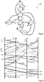
- Figure 10 is a diagram representing an example of messages transmitted between lock managers according to yet a further example embodiment.
- the labelling in Figure 10 is similar to that of Figure 9 , and will not be described again in detail.
- Figure 10 demonstrates the benefit of including in a same channel the messages LOCK_REQ and LOCK_MOV_ACK. Indeed, this ensures that when a lock manager that was a previous owner of a lock receives the message LOCK_MOV_ACK from another lock manager, such as the message issued by the lock manager LM3 in Figure 10 , all of the messages LOCK_REQ from the previous lock manager have been received.
- FIG 11 schematically illustrates the lock manager circuit 502 of Figure 5 in more detail according to an example embodiment.
- the circuit for example comprises, for each lock, a circuit block 1102 comprising a compute logic block (COMPUTE) 1104 and a register (REG) 1106, which stores an entry having the fields of Figure 6 .
- the compute logic block 1104 is for example implemented by a finite state machine.
- the compute logic block 1104 for each lock for example receives a corresponding output of four demultiplexers 1108, 1110, 1112 and 1114 that respectively receive, as the target (TGT), signals from: the host processing device (CPU CMD); the response channel (RESPONSE TGT); the move channel (MOVE TGT); and the request channel (REQUEST TGT).
- the demultiplexers 1108, 1110, 1112 and 1114 are for example controlled by the lock address indicated in each message to direct the message to the compute logic block 1104 of the corresponding lock.
- Buffers 1116 are for example provided between each demultiplexer 1108, 1110, 1112 and 1114 and the respective compute logic blocks 1104. In some embodiments, the buffers 1116 are FIFOs.
- the number Nb of locks and thus the number of circuit blocks 1102, is for example chosen based on the maximum number of locks expected to be used in the multi-core architecture. In some embodiments Nb is equal to at least 16, and in some cases is equal to up to 256.
- the compute logic block 1104 for example generates output signals to four round robin switches (RR) 1118, 1120, 1122 and 1124, which respectively provide the messages from the compute logic blocks 1104 to: a host processing device output (CPU CMD RSP); and signals to the message initiators (INI) on the response channel (RESPONSE INI); the move channel (MOVE INI); and the request channel (REQUEST INI).
- RR round robin switches
- Figure 11 corresponds to a case in which there is one compute logic block 1104 per lock, in alternatively embodiments it would be possible to mutualize one or more compute logic blocks 1104 for use by more than one lock.
- Figure 12 is a state diagram 1200 representing operation of the compute logic block 1104 of Figure 11 according to an example embodiment.
- a lock manager remains in a state NO INIT until a transition to a state INIT, represented by an arrow "1", in response to the reception of a lock creation command from the host processing device.
- the broadcast message LOCK_INIT is for example transmitted.
- an arrow "A” if however, while in the state NO INIT, the lock manager receives a message other than LOCK_INIT, or a CPU message other than lock create, an error message LOCK_ERR is for example generated.
- the lock manager remains in the state INIT until the message LOCK_ACK has been received from each other lock manager.
- the "owner” field is set to true
- the "pointer” field is set to the ID of the lock manager
- the state transitions to a state FREE, as represented by an arrow "2”.
- the state transitions back to the state NO INIT as represented by an arrow "F"
- a return error is for example generated.
- the state FREE is also for example reached directly from the state NO INIT if the message LOCK_INIT is received.
- the "owner” field is set to false and the "pointer” field is set to the identifier of the requesting lock manager indicated in the LOCK_INIT message.
- a transition to a state LOCKED occurs if the lock is requested by a processing thread and the lock is owned by the lock manager.
- the fairness counter is for example decremented, and a response to the host processing device is generated indicating that the lock has been successfully acquired.
- a transition from the state FREE to a state PENDING occurs if the lock is not currently owned by the lock manager and the "waiting" field is false, or if the "waiting" field is true and the lock is not currently owned by the lock manager.
- the message LOCK_REQ is sent to the lock manager designated in the "pointer" field.
- a transition to the state LOCKED for example occurs if the message LOCK_MOV is received and the new pointer is equal to the ID of the lock manager.
- the fairness counter is decremented, the "owner" field is set to true, the pointer is updated, and the message LOCK_MOV_ACK is sent.
- a transition from the state PENDING to a state WAIT occurs when the message LOCK_LOCKED is received.
- the "waiting" field is set to true, and the host processing device is informed that the lock is locked.
- a transition from the state FREE to the state WAIT occurs if the lock manager is not the owner of the lock and the "waiting" field is true, the host processing device is also informed that the lock is locked.
- a transition from the state WAIT to a state RESERVED occurs if the signal LOCK_MOV is received and the new pointer is equal to the ID of the lock manager.
- the "owner” field is then set to true, the “waiting” field is set to false, the "pointer” field is updated, and the signal LOCK_MOV_ACK is sent.
- a transition from the state LOCKED to a state TRANSFER for example occurs if the host processing device requests the release of the lock, the "next cluster” field is not empty, and the "waiting" field is false or the fairness counter has reached zero, the "owner” field is set to false, the "old” field is set to true, the pointer is set to the next cluster, and the counter of the messages MOV_ACK is set low.
- the broadcast message LOCK_MOV is also sent to the other lock managers.
- a transition from the state TRANSFER to the state FREE for example occurs if the message LOCK_MOV_ACK has been received from all of the other lock managers, the message LOCK_NEXT_ACK has been received in response to each transmitted message LOCK_NEXT_CLUSTER, and there is a lock manager in the waiting list. In response, the "owner" and “old” fields are set to false, and the message LOCK_MOVED is sent.
- a transition from the state FREE to the state TRANSFER for example occurs if the message LOCK_REQ is received and the "owner" field is true.
- the "owner” field is set to false, the pointer field is set to the ID of the requesting lock manager, the "old” field is set to true, the message LOCK_MOV is sent, and the counter of the number of received messages MOV_ACK is set to zero.
- the arrows "C" indicates when the lock manager will remain in the states LOCKED and RESERVED.
- the conditions for this, and the response, are for example any of the following:
- the arrow “D” indicates when the lock manager will transition from the state LOCKED to the state RESERVED, which for example occurs when the host processing devices issues an unlock command, the "waiting" field is true, and the “fairness counter” field is not at zero. In response, the "waiting" field is for example set to false, and an interrupt is sent to the host processing device to wake the processing thread.
- the arrow "G" indicates when the lock manager will remain in the state TRANSFER.
- the conditions for this, and the response, are for example any of the following:
- lock requests could be broadcast, as will now be described in relation with Figure 13 .
- Figure 13 is a diagram representing an example of messages transmitted between lock managers. The labelling in Figure 13 is similar to that of Figure 9 , and will not be described again in detail.
- a lock manager receiving the message LOCK_REQ always responds according to one of the following:
- a lock manager receives a message LOCK_NEXT_CLUSTER for a lock that it owns, but which has already been freed, the lock is directly transferred to the next lock manager.
- the true state of the "old" field implies that all messages should be responded to with the message LOCK_LOCKED, and the requests are sent to the new owner by sending the message LOCK_NEXT_CLUSTER.
- the "pointer” field for example stores a pointer to the lock manager to which the lock was transferred.
- the message LOCK_REQ is responded to by all of the other lock managers with either the message LOCK_LOCKED, the message LOCK_MOV or the message LOCK_REQ_ACK.
- a lock manager receives, in response to the message LOCK_REQ, more than one reply that is different to LOCK_REQ_ACK. If the first response is the message LOCK_LOCKED, the lock manager for example enters the WAIT state, and transitions again when the message LOCK_MOV is received. If however the first response is the message LOCK_MOV, the lock manager for example transitions to the state RESERVED or LOCKED, and ignores the other responses, although they are still read in order to empty the reception buffers 1116 of the lock manager.
- a new type of message LOCK_REQ_ACK is for example used in this modified protocol, this message being sent by a lock manager that does not own a lock in order to acknowledge the request.
- a timeout is set so that the message LOCK_REQ is retransmitted if a response has not been received from all of the lock managers within a certain time delay.
- the message LOCK_MOV_ACK can be omitted, and the "old" field in each lock entry can also be omitted.
- the message LOCK_MOVED can be omitted.
- transitions represented by the arrows "3", “6", “8” and “11” are modified as follows with respect to the above description of Figure 12 , the other transitions for example being the same.
- An advantage of the embodiments described herein is that a decentralized lock management system is implemented in which the lock management involves relatively few message transmissions between lock managers, thereby leading to a relatively low communications burden on the network.
- the decentralization of the lock management permits information of the state of a lock to be obtained in only two network requests, compared to at least three in the prior art.
- the protocol described herein based on a fairness counter and lock waiting list which favors a lock being reused by a processing thread of the processing device associated with the lock manager that owns the lock over a transfer of the lock, leads to an overall reduction in the number of lock transfers, and thus a gain in performance.
- one or more of the processing devices corresponds to a cluster of processors sharing a same lock manager, it has been found that the probability of reuse of a lock by a processor in a same cluster is relatively high, leading to a further reduction in the number of lock transfers.
- a function of task migration between processing devices could be implemented using one or more further message types, allowing lock ownership to transfer when the corresponding processing thread using the lock migrates.
Landscapes
- Engineering & Computer Science (AREA)
- Software Systems (AREA)
- Theoretical Computer Science (AREA)
- Physics & Mathematics (AREA)
- General Engineering & Computer Science (AREA)
- General Physics & Mathematics (AREA)
- Multimedia (AREA)
- Multi Processors (AREA)
Applications Claiming Priority (1)
| Application Number | Priority Date | Filing Date | Title |
|---|---|---|---|
| FR1858803A FR3086426B1 (fr) | 2018-09-26 | 2018-09-26 | Gestionnaire de verrous pour architecture multicoeurs |
Publications (1)
| Publication Number | Publication Date |
|---|---|
| EP3629171A1 true EP3629171A1 (de) | 2020-04-01 |
Family
ID=65243887
Family Applications (1)
| Application Number | Title | Priority Date | Filing Date |
|---|---|---|---|
| EP19198447.5A Ceased EP3629171A1 (de) | 2018-09-26 | 2019-09-19 | Schlossverwalter für multikernarchitekturen |
Country Status (3)
| Country | Link |
|---|---|
| US (1) | US11397625B2 (de) |
| EP (1) | EP3629171A1 (de) |
| FR (1) | FR3086426B1 (de) |
Families Citing this family (3)
| Publication number | Priority date | Publication date | Assignee | Title |
|---|---|---|---|---|
| US11782720B2 (en) * | 2020-11-16 | 2023-10-10 | Ronald Chi-Chun Hui | Processor architecture with micro-threading control by hardware-accelerated kernel thread |
| CN113377795B (zh) * | 2021-06-23 | 2025-03-18 | 北京沃东天骏信息技术有限公司 | 一种消息处理的方法和装置 |
| US12411761B1 (en) * | 2024-03-07 | 2025-09-09 | Nvidia Corporation | Fully cache coherent virtual partitions in multitenant configurations in a multiprocessor system |
Citations (4)
| Publication number | Priority date | Publication date | Assignee | Title |
|---|---|---|---|---|
| US20050216461A1 (en) * | 2004-03-27 | 2005-09-29 | Cisco Technology, Inc., A California Corporation | Bypassing native storage operations by communicating protected data within locking messages using a lock manager independent of the storage mechanism |
| US8086579B1 (en) * | 2002-01-22 | 2011-12-27 | Oracle International Corporation | Semantic response to lock requests to reduce coherence overhead in multi-node systems |
| EP2983089A1 (de) * | 2013-04-01 | 2016-02-10 | Huawei Technologies Co., Ltd. | Verfahren, vorrichtung und chip zur durchführung eines gegenseitigen exklusiven betriebs von mehreren threads |
| WO2017018976A1 (en) * | 2015-07-24 | 2017-02-02 | Hewlett Packard Enterprise Development Lp | Lock manager |
Family Cites Families (1)
| Publication number | Priority date | Publication date | Assignee | Title |
|---|---|---|---|---|
| US6950913B2 (en) * | 2002-11-08 | 2005-09-27 | Newisys, Inc. | Methods and apparatus for multiple cluster locking |
-
2018
- 2018-09-26 FR FR1858803A patent/FR3086426B1/fr active Active
-
2019
- 2019-09-19 EP EP19198447.5A patent/EP3629171A1/de not_active Ceased
- 2019-09-24 US US16/580,039 patent/US11397625B2/en active Active
Patent Citations (4)
| Publication number | Priority date | Publication date | Assignee | Title |
|---|---|---|---|---|
| US8086579B1 (en) * | 2002-01-22 | 2011-12-27 | Oracle International Corporation | Semantic response to lock requests to reduce coherence overhead in multi-node systems |
| US20050216461A1 (en) * | 2004-03-27 | 2005-09-29 | Cisco Technology, Inc., A California Corporation | Bypassing native storage operations by communicating protected data within locking messages using a lock manager independent of the storage mechanism |
| EP2983089A1 (de) * | 2013-04-01 | 2016-02-10 | Huawei Technologies Co., Ltd. | Verfahren, vorrichtung und chip zur durchführung eines gegenseitigen exklusiven betriebs von mehreren threads |
| WO2017018976A1 (en) * | 2015-07-24 | 2017-02-02 | Hewlett Packard Enterprise Development Lp | Lock manager |
Non-Patent Citations (1)
| Title |
|---|
| KUOCARTERKURAMKOTE: "MP-LOCKs: Replacing Hardware Synchronization Primitives with Message Passing", PROCEEDINGS FIFTH INTERNATIONAL SYMPOSIUM ON HIGH-COMPUTER ARCHITECTURES, 9 January 1999 (1999-01-09) |
Also Published As
| Publication number | Publication date |
|---|---|
| FR3086426A1 (fr) | 2020-03-27 |
| US11397625B2 (en) | 2022-07-26 |
| US20200097336A1 (en) | 2020-03-26 |
| FR3086426B1 (fr) | 2021-10-29 |
Similar Documents
| Publication | Publication Date | Title |
|---|---|---|
| Nowatzyk et al. | The S3. mp scalable shared memory multiprocessor | |
| US6502136B1 (en) | Exclusive control method with each node controlling issue of an exclusive use request to a shared resource, a computer system therefor and a computer system with a circuit for detecting writing of an event flag into a shared main storage | |
| US9400821B2 (en) | Memory bus protocol to enable clustering between nodes of distinct physical domain address spaces | |
| US5434975A (en) | System for interconnecting a synchronous path having semaphores and an asynchronous path having message queuing for interprocess communications | |
| TW544589B (en) | Loosely coupled-multi processor server | |
| JP3987162B2 (ja) | 読取り−共有トランザクションのための強化ブロッキング・メカニズムを含むマルチプロセス・システム | |
| CN101625664B (zh) | 满足部分写和非监听存取之间的存储器排序要求 | |
| JP3748774B2 (ja) | キャッシュコヒーレンス共用ディスクコンピュータシステムにおけるi/o転送 | |
| EP0801349B1 (de) | Deterministisches Kohärenzprotokoll für verteilten Multicache-Speicher | |
| US6986005B2 (en) | Low latency lock for multiprocessor computer system | |
| US5179665A (en) | Microprocessor information exchange with updating of messages by asynchronous processors using assigned and/or available buffers in dual port memory | |
| US20070079074A1 (en) | Tracking cache coherency in an extended multiple processor environment | |
| EP1906313A1 (de) | Speicherverwaltung in einem gemeinsam genutzten Speichersystem | |
| US20100115195A1 (en) | Hardware memory locks | |
| JP2018109965A (ja) | データ処理 | |
| JP2000112910A (ja) | 非一様メモリ・アクセス・コンピュ―タ・システム及びその操作方法 | |
| JP2009525536A (ja) | 適応型の領域ロック処理 | |
| US5852719A (en) | System for transferring data over a network in which a data source sends only a descriptor which a data sink uses to retrieve data | |
| JPH10187470A (ja) | スピンロック動作を最適化する装置を含むマルチプロセス・システム | |
| JP2002182976A (ja) | マルチプロセッサ・システムにおけるメモリ・アクセスの動的直列化 | |
| US11397625B2 (en) | Lock manager for multi-core architectures | |
| US20040215773A1 (en) | Distributed shared resource management | |
| EP0296862B1 (de) | Nachrichtenaustausch zwischen Prozessoren | |
| US10229073B2 (en) | System-on-chip and method for exchanging data between computation nodes of such a system-on-chip | |
| US20190146845A1 (en) | Lock Allocation Method and Apparatus, and Computing Device |
Legal Events
| Date | Code | Title | Description |
|---|---|---|---|
| PUAI | Public reference made under article 153(3) epc to a published international application that has entered the european phase |
Free format text: ORIGINAL CODE: 0009012 |
|
| STAA | Information on the status of an ep patent application or granted ep patent |
Free format text: STATUS: REQUEST FOR EXAMINATION WAS MADE |
|
| 17P | Request for examination filed |
Effective date: 20190919 |
|
| AK | Designated contracting states |
Kind code of ref document: A1 Designated state(s): AL AT BE BG CH CY CZ DE DK EE ES FI FR GB GR HR HU IE IS IT LI LT LU LV MC MK MT NL NO PL PT RO RS SE SI SK SM TR |
|
| AX | Request for extension of the european patent |
Extension state: BA ME |
|
| STAA | Information on the status of an ep patent application or granted ep patent |
Free format text: STATUS: EXAMINATION IS IN PROGRESS |
|
| 17Q | First examination report despatched |
Effective date: 20210708 |
|
| STAA | Information on the status of an ep patent application or granted ep patent |
Free format text: STATUS: THE APPLICATION HAS BEEN REFUSED |
|
| 18R | Application refused |
Effective date: 20231021 |