EP3629355B1 - Appareil électrique et relais électromagnétique - Google Patents
Appareil électrique et relais électromagnétique Download PDFInfo
- Publication number
- EP3629355B1 EP3629355B1 EP19198894.8A EP19198894A EP3629355B1 EP 3629355 B1 EP3629355 B1 EP 3629355B1 EP 19198894 A EP19198894 A EP 19198894A EP 3629355 B1 EP3629355 B1 EP 3629355B1
- Authority
- EP
- European Patent Office
- Prior art keywords
- terminal
- section
- specific area
- seal
- electric apparatus
- Prior art date
- Legal status (The legal status is an assumption and is not a legal conclusion. Google has not performed a legal analysis and makes no representation as to the accuracy of the status listed.)
- Active
Links
Images


Classifications
-
- H—ELECTRICITY
- H01—ELECTRIC ELEMENTS
- H01H—ELECTRIC SWITCHES; RELAYS; SELECTORS; EMERGENCY PROTECTIVE DEVICES
- H01H50/00—Details of electromagnetic relays
- H01H50/14—Terminal arrangements
-
- H—ELECTRICITY
- H01—ELECTRIC ELEMENTS
- H01H—ELECTRIC SWITCHES; RELAYS; SELECTORS; EMERGENCY PROTECTIVE DEVICES
- H01H1/00—Contacts
-
- H—ELECTRICITY
- H01—ELECTRIC ELEMENTS
- H01H—ELECTRIC SWITCHES; RELAYS; SELECTORS; EMERGENCY PROTECTIVE DEVICES
- H01H50/00—Details of electromagnetic relays
- H01H50/02—Bases; Casings; Covers
- H01H50/023—Details concerning sealing, e.g. sealing casing with resin
-
- H—ELECTRICITY
- H01—ELECTRIC ELEMENTS
- H01H—ELECTRIC SWITCHES; RELAYS; SELECTORS; EMERGENCY PROTECTIVE DEVICES
- H01H2223/00—Casings
- H01H2223/002—Casings sealed
Definitions
- the present disclosure relates generally to electric apparatuses and electromagnetic relays and, specifically, to an electric apparatus and an electromagnetic relay which include a terminal.
- JP H05-234447 discloses a terminal seal structure of an electric apparatus.
- a seal groove is formed in an electric apparatus body, a terminal protrudes from a terminal hole formed in the seal groove, and a seal member is injected in the seal groove to seal a gap between the terminal and the terminal hole.
- the seal member may cure in a state where the seal member creeps up a surface of the terminal.
- the seal member on the surface of the terminal may result in that the terminal is not strongly bound to a printed wiring board.
- EP 0 468 096 A1 describes a casing for an electrical component.
- filling containers are formed into the outer wall of the bottom part, from which distribution channels lead to the individual sealing points.
- the distribution channels are split into partial channels by means of a centrally running distribution rib, as a result of which double channels with a correspondingly increased capillary effect lead to the individual sealing points.
- JP 2007 184132 A describes an electromagnetic relay composed of an electromagnetic relay main body installed on a base, a terminal protruding downward from the bottom face of the base, and a cover installed so as to cover the electromagnetic relay main body and the side wall part of the base.
- a groove part of nearly constant width and constant depth is installed at the bottom face of the base, and a sealing agent made of resin for insulating sealing is filled in the groove part, in the spacing between the side wall part of the base and the cover, and in the spacing between the base and the cover and the terminal, and the relay is adhered, fixed, and sealed.
- the present invention relates to an electric apparatus according to claim 1 or 2, and an electromagnetic relay according to claim 8.
- Claims 3 to 7 refer to specifically advantageous realizations of the electric apparatus according to claim 1 or 2.
- an electric apparatus 100 includes a resin member 1, a wall section 21, a terminal 3, and a projection section 4.
- the resin member 1 includes an attachment surface 10 facing a substrate 300.
- the wall section 21 surrounds a specific area 20 of the attachment surface 10.
- the terminal 3 protrudes from the specific area 20 to an outer side of the resin member 1.
- the projection section 4 is provided between the wall section 21 and a base 30 of the terminal 3.
- the projection section 4 has a tip end 40 exposed from a seal member 5 covering the base 30 of the terminal 3 in a state where the seal member 5 is formed in the specific area 20.
- the tip end 40 is provided apart from the terminal 3 and the wall section 21.
- the terminal 3 is disposed in a pore 301 formed in the substrate 300, and in this state, for example, solder 302 which is melted is poured into the pore 301 and cures, which enables the terminal 3 to be bound to the substrate 300.
- FIG. 1B shows a conventional electric apparatus 100 in which a resin member 1 is not provided with a projection section 4.
- a base 30 of a terminal 3 is sealed with a seal member 5.
- the seal member 5 before curing is in a liquid state (hereinafter the seal member 5 before curing is also referred to as seal liquid).
- seal liquid When the base 30 is covered with the seal liquid, the seal liquid may creep up a surface of the terminal 3.
- a reason for the creeping up is that the seal liquid disposed around the base 30 moves along the surface of the terminal 3 due to surface tension.
- a reason for the movement is probably that the wettability of the terminal 3 made of metal is higher than that of the resin member 1.
- the terminal 3 is disposed in a pore 301, and in this state, solder 302 which is melted is poured into the pore 301, but at this time, part of the seal member 5 which is located in the pore 301 may hinder the solder 302 from flowing into the pore 301. In this case, it may not be possible to strongly bind the terminal 3 to the substrate 300.
- the electric apparatus 100 of the present embodiment includes the projection section 4 as illustrated in FIG. 1A , and the tip end 40 of the projection section 4 is apart from the terminal 3 and the wall section 21. That is, between the terminal 3 and the wall section 21, the projection section 4 is provided. Due to the projection section 4, a location from where the seal liquid starts creeping up is close to the terminal 3, and therefore, it is possible to reduce the creeping up of the seal liquid on the surface of the terminal 3.
- the tip end 40 of the projection section 4 is exposed from the seal member 5, and therefore, it is also possible to reduce spreading of the seal liquid around the projection section 4 to creep up the surface of the terminal 3.
- the creeping up of the seal member 5 is reduced, and therefore, when the solder 302, which is melted, is poured into the pore 301 formed in the substrate 300 with the terminal 3 being disposed in the pore 301, the seal member 5 is less likely to hinder the solder 302 to flow into the pore 301.
- the solder 302 easily flows into the pore 301, and therefore, it is easy to strongly bind the terminal 3 to the substrate 300.
- the electric apparatus 100 according to the present embodiment will be described in detail below.
- the electric apparatus 100 includes the resin member 1. First, the resin member 1 will be described.
- the resin member 1 includes the attachment surface 10, and the shape of the resin member 1 is not particularly limited. As illustrated in FIG. 2A , the resin member 1 of the present embodiment has a rectangular box shape. Specifically, the resin member 1 includes the attachment surface 10, an opposite surface 11 which is apart from the attachment surface 10 and which is on an opposite side of the attachment surface 10, and four side surfaces 12 located between the attachment surface 10 and the opposite surface 11. Thus, the resin member 1 of the present embodiment has a shape of a box including the opposite surface 11, the attachment surface 10, and the four side surfaces 12.
- the attachment surface 10, the side surfaces 12, and the opposite surface 11 may be a surface of a single member or surfaces of separate members.
- a member including the attachment surface 10 and the four side surfaces 12 and a member including the opposite surface 11 are separate members.
- the member including the opposite surface 11 may function as a lid of a container which is the member including the attachment surface 10 and the four side surfaces 12.
- various components may be accommodated in a space in the container.
- the material for the resin member 1 is not particularly limited as long as a resin is adopted.
- the material for the resin member 1 may be, for example, a thermoplastic resin or a thermosetting resin.
- the thermoplastic resin include polyethylene (PE), polypropylene (PP), polystyrene (PS), an AS resin, an ABS resin, a methacrylate (PMMA) resin , a polyvinyl chloride (PVC) resin, polyoxymethylene (POM), polyamide (PA), polycarbonate (PC), modified polyphenylene ether (PPE), polybutylene terephthalate (PBT), polyethylene terephthalate (PET), polysulfone (PSF), polyethersulfone (PES), polyphenylene sulfide (PPS), polyamideimide (PEI), polymethylpentene (TPX), and liquid crystal polymer (LCP).
- PE polyethylene
- PP polypropylene
- PS polystyrene
- AS resin an AS resin
- thermosetting resin examples include phenolic (PF) resin, a urea (UF) resin, a melamine (MF) resin, an epoxy (EP) resin, a diallyl phthalate (PDAP) resin, an unsaturated polyester (UP) resin, polyimide (PI), and polyurethane (PUR).
- PF phenolic
- UF urea
- MF melamine
- EP epoxy
- PDAP diallyl phthalate
- UP unsaturated polyester
- PI polyimide
- PUR polyurethane
- the attachment surface 10 has a rectangular shape and includes a plurality of seal areas 2 in each of which the seal member 5 is to be formed. Specifically, the attachment surface 10 includes four seal areas 2 (see FIG. 2A ). Each of the seal areas 2 is surrounded by the wall section 21 rising to the outer side of the resin member 1. From each of the seal areas 2, the terminal 3 protrudes to the outer side of the resin member 1.
- the plurality of seal areas 2 include one or more specific areas 20.
- the four seal areas 2 include two specific areas 20.
- the specific area 20 means an area which is included in the plurality of seal areas 2 and in which the projection section 4 is further provided.
- one terminal 3 protrudes from one specific area 20. In this case, it is possible to more securely seal the base 30 of the terminal 3 with the seal member 5.
- the attachment surface 10 is provided with a plurality of leg sections 13 (see FIG. 2A ).
- the leg sections 13 enable a gap to be provided between the substrate 300 and the attachment surface 10 when the electric apparatus 100 is attached to the substrate 300. That is, the leg sections 13 are configured to serve as spacers.
- the shape and the height of the leg sections 13 are not particularly limited as long as they enable a gap to be provided between the substrate 300 and the attachment surface 10.
- locations where the leg sections 13 are provided on the attachment surface 10 are not particularly limited as long as they enable a gap to be provided between the substrate 300 and the attachment surface 10.
- the number of leg sections 13 provided on the attachment surface 10 is not particularly limited as long as it enables a gap to be provided between the substrate 300 and the attachment surface 10.
- the base 30 of the terminal 3 protruding from each seal area 2 is covered with the seal member 5 (see FIG. 2B ).
- respective seal members 5 are formed in the plurality of seal areas 2.
- the seal member 5 is accommodated in a space surrounded by one seal area 2 and one wall section 21, and one terminal 3 protrudes from the seal member 5.
- the seal member 5 is formed in each of the four seal areas 2.
- At least two of the plurality of seal areas 2 preferably align to at least partially overlap with each other in a direction along one side of the attachment surface 10.
- two seal areas 2 (two specific areas 20) align to partially overlap with each other.
- the seal liquid is supplied to one of the seal areas 2, and then, the seal liquid is supplied to the other of the seal areas 2.
- the two seal areas 2 align to partially overlap with each other in the direction along the side 101. Therefore, it is possible to reduce a travel distance of a device for supplying the seal liquid and to efficiently supply the seal liquid.
- two seal areas 2 align to partially overlap with each other.
- two seal areas 2 align to partially overlap with each other.
- the material for the seal member 5 is not particularly limited as long as a resin is adopted, but the seal member 5 is preferably made of a thermosetting resin.
- the seal member 5 is preferably made of a thermosetting resin.
- the thermosetting resin has a property of liquefying before curing. Therefore, supplying the seal liquid to the seal area 2 enables the seal liquid to cure with the seal liquid being provided in the seal area 2. Thus, the seal member 5 easily seals the base 30 of the terminal 3.
- the thermosetting resin for example, an epoxy resin may be used.
- the attachment surface 10 includes the specific areas 20.
- the shape of each specific area 20 is not particularly limited, but each specific area 20 of the present embodiment has a rectangular shape (see FIG. 3 ).
- the location of the specific area 20 in the attachment surface 10 is not particularly limited. In other words, the location of the specific area 20 in the attachment surface 10 is determined based on the location of the terminal 3.
- the wall section 21 surrounds, as described above, the specific area 20.
- the wall section 21 is continuous to the specific area 20 and rises from the specific area 20.
- the angle between the specific area 20 and the wall section 21 may be 90°, may be larger than or equal to 90°, or may be smaller than or equal to 90°.
- the height of the wall section 21 is not particularly limited but is determined such that the seal member 5 can be accommodated in a space formed by the specific area 20 and the wall section 21.
- the height of the wall section 21 may be uniform or may be non-uniform.
- each specific area 20 and its corresponding wall section 21 form a recess in the attachment surface 10 (see FIG. 2A ).
- the seal member 5 can be accommodated in the recess formed by the specific area 20 and the wall section 21.
- the specific area 20 is a bottom surface
- the wall section 21 is a sidewall.
- each wall section 21 surrounds its corresponding specific area 20.
- an upper edge of the wall section 21 defines an opening.
- a virtual surface including the opening is referred to as an opening surface 210 (see FIG. 4 ).
- the specific area 20 and the wall section 21 form the recess in the attachment surface 10, and therefore, the opening surface 210 is also a virtual surface representing a case where the recess is not formed in the attachment surface 10.
- the terminal 3 protrudes from the specific area 20 to the outer side of the resin member 1. Specifically, the terminal 3 protrudes from an inner part of the resin member 1 through the opening formed in the specific area 20 to the outer side of the resin member 1. In the present embodiment, the terminal 3 protrudes from a location deviated from the center of the specific area 20.
- the base 30 of the terminal 3 in the present disclosure is a base of a portion of the terminal 3 protruding from the resin member 1, in other words, a root part (part close to the specific area 20) of the terminal 3 of portion protruding from the specific area 20 (opening of the specific area 20).
- the terminal 3 of the present embodiment has a flat plate shape and includes a flat surface 31 and a flat surface 32 located on an opposite side of the flat surface 31 (see FIG. 3 ).
- the specific area 20 is divided into a region at the side of the flat surface 31 and a region at the side of the flat surface 32 with the terminal 3 as a boarder.
- the area of the region at the side of the flat surface 31 is equal to the region at the side of the flat surface 32.
- the area of the region at the side of the flat surface 31 is not equal to the area of the region at the side of the flat surface 32.
- the seal liquid is preferably supplied to the larger in area of the region at the side of the flat surface 31 and the region at the side of the flat surface 32.
- the area of the region at the side of the flat surface 32 is larger than the area of the region at the side of the flat surface 31, and therefore, the seal liquid is more easily supplied to the region of the specific area 20 at the side of the flat surface 32.
- the projection section 4 of the present embodiment has a rectangular shape and extends in a width direction of the flat surface 32 of the terminal 3. As described above, the projection section 4 reduces creeping up of the seal liquid on the surface of the terminal 3, the seal liquid being formed in the specific area 20 (see FIG. 1A ). As in the present embodiment, when the terminal 3 has flat plate shape having a flat surface 32, the seal liquid attempts to creep up the flat surface 32, but the projection section 4 extending in the width direction of the flat surface 32 enables creeping up of the seal liquid on the flat surface 32 to effectively be reduced.
- the distance L1 between the wall section 21 and the projection section 4 in the first order is preferably longer than a distance L2 between the terminal 3 and the projection section 4.
- Providing the projection section 4 can reduce the creeping up of the seal liquid more than not providing the projection section 4, but when the distance L2 is longer than the distance L1, the projection section 4 may not satisfactorily reduce the creeping up of the seal liquid.
- the projection section 4 when the distance L1 is longer than the distance L2, the projection section 4 satisfactorily reduce the creeping up of the seal liquid on the surface of the terminal 3.
- the projection section 4 is provided in each specific area 20. Specifically, the projection section 4 is provided between the wall section 21 and the terminal 3 in the specific area 20. More specifically, the projection section 4 is provided between the flat surface 32 of the terminal 3 and a portion of the wall section 21 facing the flat surface 32 in the specific area 20.
- the seal liquid When the seal liquid is supplied to the region at the side of the flat surface 32 in the specific area 20, the seal liquid cannot linearly reach the flat surface 31 but has to spread in a curved manner toward the flat surface 31. Thus, the seal liquid at first reaches the flat surface 32 and then reaches the flat surface 31. In the course of flow of the seal liquid, the viscosity of the seal liquid continues increasing. Thus, the viscosity of the seal liquid reaching the flat surface 32 tends to be lower than the viscosity of the seal liquid reaching the flat surface 31. When the viscosity of the seal liquid is low, the seal liquid easily creeps up the surface of the terminal 3, and therefore, the seal liquid reaching the flat surface 32 more easily creeps up the surface of the terminal 3 than the seal liquid reaching the flat surface 31 does.
- the projection section 4 between the flat surface 32 of the terminal 3 and a portion of the wall section 21 facing the flat surface 32 enables a time required for the seal liquid to reach the flat surface 32 and to cover the flat surface 32 to be increased, and thereby, it is possible to increase the viscosity of the seal liquid when the seal liquid covers the flat surface 32. This enables creeping up of the seal liquid on the flat surface 32 to effectively be reduced.
- the projection section 4 has a flat surface (counter surface) facing the flat surface 32 of the terminal 3.
- the dimension in a width direction of the flat surface (counter surface) of the projection section 4 is larger than the dimension in a width direction of the flat surface 32 of the terminal 3. In this case, it is possible to further increase a time required for the seal liquid to reach the flat surface 32.
- the distance L2 between the projection section 4 and the terminal 3 is preferably shorter than a distance L3 between the wall section 21 and the terminal 3 in the second order.
- the distance L2 is shorter than the distance L3
- the seal liquid is less likely to spread between the flat surface 31 of the terminal 3 and the wall section 21, but when the distance L3 is longer than the distance L2, it is possible to facilitate spreading of the seal liquid between the flat surface 32 of the terminal 3 and the wall section 21.
- the surface roughness of the specific area 20 facing the opening surface 210 of the wall section 21 is preferably greater than the surface roughness of projection section 4.
- the seal liquid easily flows in a region having a greater surface roughness.
- the surface roughness of the specific area 20 is greater than the surface roughness of the side surface of the projection section 4, which enables the seal liquid to easily flow on the specific area 20.
- the seal liquid supplied to the specific area 20 easily covers the base 30 of the terminal 3, and it becomes easy to seal the base 30 of the terminal 3 by the seal member 5.
- An example of a method for increasing the surface roughness of the specific area 20 is, for example, emboss processing or the like performed on the surface of the specific area 20.
- each specific area 20 preferably has a slope section 201 formed such that the distance (L4 in FIG. 4 ) between the opening surface 210 of the wall section 21 and the specific area 20 facing the opening surface 210 increases as the distance from the wall section 21 to the terminal 3 decreases.
- the seal liquid is supplied to the slope section 201, thereby allowing the seal liquid to spread along the slope of the slope section 201. Since the slope section 201 of the present embodiment slopes from the wall section 21 toward the terminal 3, it is possible to allow the seal liquid to spread toward the terminal 3. Thus, it becomes easy to cover the base 30 of the terminal 3 with the seal liquid, and it becomes easy to seal the base 30 of the terminal 3 with the seal member 5.
- the slope section 201 reduces the time required for the seal liquid to cover the base 30 of the terminal 3, and thereby, it is easy to cover the base 30 of the terminal 3 with the seal liquid before the viscosity of the seal liquid is excessively increased.
- the specific area 20 has the slope section 201, but it is also preferable, as illustrated in FIG. 2A , that the seal area 2 provided with no projection section 4 has the slope section 201.
- the seal liquid is supplied to the slope section 201 of each seal area 2.
- the slope sections 201 of at least two of the plurality of seal areas 2 preferably align to partially overlap with each other in a direction along one side of the attachment surface 10. It is possible to reduce a travel distance of a device for supplying the seal liquid, which enables the seal liquid to be efficiently supplied.
- the electric apparatus 100 of the present embodiment includes a guide section 202 provided in the specific area 20 and extending in a direction from the wall section 21 toward the terminal 3.
- the guide section 202 is preferably a projection or a groove.
- the guide section 202 of the present embodiment extends in the direction from the wall section 21 toward the terminal 3 and thus allows the seal liquid to flow toward the terminal 3.
- it becomes easy to cover the base 30 of the terminal 3 with the seal liquid and it becomes easy to seal the base 30 of the terminal 3 with the seal member 5.
- the guide section 202 reduces the time required for the seal liquid to cover the base 30 of the terminal 3, and thereby, it is possible to cover the base 30 of the terminal 3 with the seal liquid before the viscosity of the seal liquid is excessively increased.
- Only one guide section 202 may be provided, two guide sections 202 may be provided, or three or more guide sections 202 may be provided. In the electric apparatus 100 of the present embodiment, two guide sections 202 are provided.
- the guide sections 202 are provided in the specific area 20, but as illustrated in FIG. 2A , it is also preferable that the guide sections 202 are provided in the seal area 2 provided with no projection section 4. Also in this case, it is easy to cover the base 30 of the terminal 3 protruding from the seal area 2 with the seal liquid.
- the specific area 20 has the slope section 201 and the guide sections 202, and the guide sections 202 are provided in the slope section 201.
- the seal liquid supplied to the slope section 201 flows to spread toward the terminal 3, and additionally, the guide section 202 enables the seal liquid to spread toward the terminal 3.
- the slope section 201 and the guide sections 202 particularly reduces a time required for the seal liquid to cover the bae 30 of the terminal 3.
- a seal area 2 other than the specific area 20 is not provided with the projection section 4.
- the projection section 4 enables creeping up of the seal liquid on the surface of the terminal 3 to be reduced.
- the seal area 2 provided with no projection section 4 for example, the distance between the flat surface 31 of the terminal 3 and the wall section 21 and the distance between the flat surface 32 of the terminal 3 and the wall section 21 are reduced, thereby reducing creeping up of the seal liquid.
- the distance between the flat surface 31 and the wall section 21 and the distance between the flat surface 32 and the wall section 21 are adjustable by the location at which the terminal 3 protrudes from the seal area 2 or the shape of the seal area 2.
- the seal area 2 is determined at least such that each of the distance between the flat surface 31 and the wall section 21 and the distance between the flat surface 32 and the wall section 21 is larger than the distance between the side surface of the terminal 3 and the wall section 21.
- the configuration of the electric apparatus 100 is not limited to the above-described example.
- the specific area 20 and the wall section 21 form a recess in the attachment surface 10. That is, the specific area 20 is surrounded by the wall section 21 recessed from the attachment surface 10, but this should not be construed as limiting.
- the specific area 20 may be surrounded by the wall section 21 protruding from the attachment surface 10.
- the seal member 5 can be accommodated in a space surrounded by the specific area 20 and the wall section 21.
- the seal area 2 provided with no projection section 4 is also surround by the wall section 21 recessed from the attachment surface 10, but this should not be construed as limiting.
- the seal area 2 may be surrounded by the wall section 21 protruding from the attachment surface 10.
- the specific area 20 has the slope section 201, but this should not be construed as limiting.
- the specific area 20 does not have to have the slope section 201.
- the guide sections 202 are provided in the specific area 20, but this should not be construed as limiting.
- the guide sections 202 do not have to be provided in the specific area 20.
- the guide sections 202 are projections provided in the specific area 20, but this should not be construed as limiting.
- the guide sections 202 may be grooves formed in the specific area 20.
- the terminal 3 has a flat plate shape having the flat surface 32, and the projection section 4 extends in a width direction of the flat surface 32, but this should not be construed as limiting.
- the terminal 3 has a flat plate shape having the flat surface 32, and in a width direction of the flat surface 32, a central part of the projection section 4 is located between the terminal 3 and an end of the projection section 4.
- the seal liquid creeps up the flat surface 32 of the terminal 3
- the seal liquid more easily creeps up at the central part than at the end in the width direction of the flat surface 32.
- the central part of the projection section 4 is between the end and the terminal 3, it is possible to reduce creeping up of the seal liquid at the central part in the width direction of the flat surface 32. This enables creeping up of the seal liquid to effectively be reduced.
- a projection section 4 is provided in a specific area 20, and the center of the projection section 4 is closest to a flat surface 32 of a terminal 3 in a width direction of the flat surface 32 of the terminal 3. Moreover, a distance between the projection section 4 and the terminal 3 (flat surface 32) increases as a distance from the center to each end of the projection section 4 decreases.
- a projection section 4 is provided in a specific area 20, and the center of the projection section 4 and a peripheral part of the center are closest to a flat surface 32 of a terminal 3 in a width direction of the flat surface 32 of the terminal 3. Moreover, a distance between the projection section 4 and the terminal 3 (flat surface 32) increases as a distance from the peripheral part of the center to each end of the projection section 4 decreases.
- a projection section 4 is provided in a specific area 20, the center of the projection section 4 is closest to a flat surface 32 of a terminal 3 in a width direction of the flat surface 32 of the terminal 3. Moreover, a distance between the projection section 4 and the terminal 3 (flat surface 32) gradually increases as a distance from the center to each end of the projection section 4 decreases.
- a projection section 4 is provided in a specific area 20, and the center of the projection section 4 is closest to a flat surface 32 of a terminal 3 in a width direction of the flat surface 32 of the terminal 3. Moreover, a distance between the projection section 4 and the terminal 3 (flat surface 32) gradually increases as a distance from the center to each end of the projection section 4 decreases.
- the projection section 4 shown in FIG. 5D has a round shape in plan view.
- the projection section 4 is provided in the specific area 20 and includes a first projection section 41 and a second projection section 42.
- the first projection section 41 is located, in a width direction of a flat surface 32 of a terminal 3, at a central part of the flat surface 32 of the terminal 3 and is located between the second projection section 42 and the flat surface 32.
- the second projection section 42 is located farther away from the flat surface 32 than the first projection section 41 is, and the second projection section 42 extends in the width direction of the flat surface 32 of the terminal 3.
- the projection section 4 in FIG. 5E also has a central part and ends in the width direction of the flat surface 32 of the terminal 3, and the central part is closer to the terminal 3 than the ends are.
- a projection section 4 is provided in a specific area 20, and the center of the projection section 4 is closest to a flat surface 32 of a terminal 3 in a width direction of the flat surface 32 of the terminal 3. Moreover, a distance between the projection section 4 and the terminal 3 (flat surface 32) increases as a distance from the center to each end of the projection section 4 decreases.
- the projection section 4 shown in FIG. 5F has a triangular shape in plan view.
- a projection section 4 is provided in a specific area 20, and the center of the projection section 4 and a peripheral part of the center are closest to a flat surface 32 of a terminal 3 in a width direction of the flat surface 32 of the terminal 3. Moreover, a distance between the projection section 4 and the terminal 3 (flat surface 32) increases as a distance from the peripheral part of the center to each end of the projection section 4 decreases.
- the projection section 4 shown in FIG. 6A has a trapezoidal shape in plan view.
- the terminal 3 has a flat plate shape having the flat surface 32, and the projection section 4 extends in a width direction of the flat surface 32, but this should not be construed as limiting.
- the projection section 4 does not have to extend in the width direction of the flat surface 32 of the terminal 3.
- a projection section 4 provided in a specific area 20 is provided only in the periphery of the center in a width direction of a flat surface 32 of a terminal 3.
- the terminal 3 protrudes from the location deviated from the center of the specific area 20, but this should not be construed as limiting.
- the terminal 3 may protrude from the center of the specific area 20.
- a terminal 3 which has a flat plate shape protrudes from the center of a specific area 20.
- a projection section 4 is provided between a flat surface 31 of the terminal 3 and a wall section 21, and between a flat surface 32 of the terminal 3 and the wall section 21, a projection section 4 is provided.
- the projection section 4 provided between the flat surface 31 and the wall section 21 is divided at the center of the projection section 4 in a width direction of the flat surface 31.
- the projection section 4 provided between the flat surface 32 and the wall section 21 is divided at the center of the projection section 4 in a width direction of the flat surface 32.
- a terminal 3 having a columnar shape protrudes from the center of the specific area 20.
- two projection sections 4 are provided in the circumference of the terminal 3. The projection sections 4 are located along the circumference of the terminal 3, and it is thus possible to effectively reduce creeping up of the seal liquid on the surface of the terminal 3.
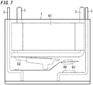
- An electromagnetic relay 600 of the present embodiment will be described below with reference to FIG. 7 .
- the electromagnetic relay 600 shown in FIG. 7 is a mere example, and design of the dimension, shape, and the like of the electromagnetic relay 600 may accordingly be changed and is not limited to the configuration shown in FIG. 7 .
- the electromagnetic relay 600 includes, for example, the electric apparatus 100 as shown in FIG. 2A .
- the electromagnetic relay 600 shown in FIG. 7 includes one resin member 1 and four terminals 3.
- the driver includes a coil 63 and an armature 62.
- the armature 62 is driven by magnetic flux generated by energization of the coil 63.
- the armature 62 drives the movable contact 61.
- the electromagnetic relay 600 includes the fixed contact 60, the movable contact 61, and the driver. Of the four terminals 3, one terminal 3 is electrically connected to the fixed contact 60, one terminal 3 is electrically connected to the movable contact 61, and two terminals 3 are electrically connected to the coil 63 included in the driver.
- the movable contact 61 is configured to come into contact with or come out of contact with the fixed contact 60.
- the driver is configured to bring the movable contact 61 into contact with or out of contact with the fixed contact 60.
- the driver may bring the movable contact 61 out of contact with the fixed contact 60 into contact with the fixed contact 60, and the driver may bring the movable contact 61 in contact with the fixed contact 60 out of contact with the fixed contact 60.
- the solder 302 is easily injected into the pore 301 with the terminal 3 being disposed in the pore 301 formed in the substrate 300, and therefore, it is possible to strongly bind the terminal 3 to the substrate 300.
- the terminal 3 can be strongly bound to the substrate 300.
- FIG. 7 shows the electromagnetic relay 600 including the electric apparatus 100.
- the electric apparatus 100 is applicable to components other than the electromagnetic relay 600.
Landscapes
- Physics & Mathematics (AREA)
- Electromagnetism (AREA)
- Connector Housings Or Holding Contact Members (AREA)
- Casings For Electric Apparatus (AREA)
Claims (8)
- Appareil électrique (100), comprenant :un élément en résine (1) ayant une surface de fixation (10) faisant face à un substrat (300) ;une section paroi (21) entourant une zone spécifique (20) de la surface de fixation (10) ;au moins une borne (3) faisant saillie à partir de la zone spécifique (20) vers un côté externe de l'élément en résine (1) ; etune section saillie (4) prévue entre la section paroi (21) et une base (30) de l'au moins une borne (3),la section saillie (4) ayant un embout (40) exposé à partir d'un élément d'étanchéité (5) recouvrant la base (30) de l'au moins une borne (3) dans un état où l'élément d'étanchéité (5) est dans la zone spécifique (20),l'embout (40) étant prévu séparément de l'au moins une borne (3) et de la section paroi (21),caractérisé en ce que :i) la zone spécifique (20) a une section pente (201) formée de telle sorte qu'une distance (L4) entre une surface d'ouverture (210) de la section paroi (21) et la zone spécifique (20) faisant face à la surface d'ouverture (210) augmente lorsqu'une distance de la section paroi (21) à l'au moins une borne (3) diminue, de telle sorte que lorsqu'un liquide d'étanchéité est appliqué sur la section pente (201), le liquide d'étanchéité est conçu pour s'étaler le long de la pente de la section pente (201) vers la borne (3), ouii) l'appareil électrique (100) comprend en outre une section guide (202) prévue dans la zone spécifique (20) et s'étendant dans une direction de la section paroi (21) vers l'au moins une borne (3), dans lequel la section guide (202) est une saillie ou une gorge, de telle sorte que lorsqu'un liquide d'étanchéité appliqué sur la zone spécifique (20) vient en contact avec la section guide (202), le liquide d'étanchéité est conçu pour s'écouler le long de la section guide (202) vers la borne (3), ouiii) une rugosité de surface de la zone spécifique (20) faisant face à une surface d'ouverture (210) de la section paroi (21) est supérieure à une rugosité de surface de la section saillie (4).
- Appareil électrique (100), comprenant :un élément en résine (1) ayant une surface de fixation (10) faisant face à un substrat (300) ;une section paroi (21) entourant une zone spécifique (20) de la surface de fixation (10) ;au moins une borne (3) faisant saillie de la zone spécifique (20) vers un côté externe de l'élément en résine (1) ; etune section saillie (4) est prévue entre la section paroi (21) et la base (30) de l'au moins une borne (3),la section saillie (4) ayant un embout (40) exposé à partir d'un élément d'étanchéité (5) recouvrant la base (30) de l'au moins une borne (3) dans un état où l'élément d'étanchéité (5) est dans la zone spécifique (20),l'embout (40) étant prévu séparément de l'au moins une borne (3) et de la section paroi (21),caractérisé en ce que :dans une direction dans laquelle la section paroi (21), la section saillie (4) et l'au moins une borne (3) sont alignées dans cet ordre étant un premier ordre, une distance (L1) entre la section paroi (21) et la section saillie (4) dans le premier ordre est plus longue qu'une distance (L2) entre l'au moins une borne (3) et la section saillie (4), oudans une direction dans laquelle la section saillie (4), l'au moins une borne (3) et la section paroi (21) sont alignées dans cet ordre étant un second ordre, une distance (L2) entre la section saillie (4) et l'au moins une borne (3) est plus courte qu'une distance (L3) entre la section paroi (21) et l'au moins une borne (3) dans le second ordre.
- Appareil électrique selon la revendication 1 ou 2, dans lequell'au moins une borne (3) inclut une seule borne (3), etla seule borne (3) fait saillie à partir de la zone spécifique (20).
- Appareil électrique (100) selon l'une quelconque des revendications 1 à 3, dans lequell'au moins une borne (3) a une forme de plaque plane ayant une surface plane (32), etla section saillie (4) s'étend dans une direction de largeur de la surface plane (32) de l'au moins une borne (3).
- Appareil électrique (100) selon l'une quelconque des revendications 1 à 4, dans lequell'au moins une borne (3) a une forme de plaque plane ayant une surface plane (32),la section faisant saillie (4) a une partie centrale et des extrémités dans une direction de largeur de la surface plane (32), etla partie centrale est plus proche de l'au moins une borne (3) que ne le sont les extrémités.
- Appareil électrique (100) selon l'une quelconque des revendications 1 à 5, dans lequel
l'élément d'étanchéité (5) est composé d'une résine thermodurcissable. - Appareil électrique (100) selon l'une quelconque des revendications 1 à 6, dans lequella surface de fixation (10) a une forme rectangulaire,la surface de fixation (10) inclut une pluralité de zones d'étanchéité (2) qui inclut la zone spécifique (20) et dans chacune desquelles l'élément d'étanchéité (5) doit être formé,chacune de la pluralité de zones d'étanchéité (2) est entourée par une section correspondante d'une pluralité de sections paroi (21) incluant la section paroi (21),une pluralité de bornes (3) incluant l'au moins une borne (3) font saillie de la pluralité de zones d'étanchéité (2) vers le côté externe de l'élément en résine (1), etau moins deux de la pluralité de zones d'étanchéité (2) s'alignent pour se chevaucher au moins partiellement dans une direction le long d'un côté de la surface de fixation (10).
- Relais électromagnétique (600), comprenant :l'appareil électrique (100) selon l'une quelconque des revendications 1 à 7 ;un contact fixe (60) ;un contact mobile (61) conçu pour se mettre en contact ou hors de contact avec le contact fixe (60) ; etun excitateur conçu pour mettre le contact mobile (61) en contact ou hors de contact avec le contact fixe (60).
Applications Claiming Priority (1)
| Application Number | Priority Date | Filing Date | Title |
|---|---|---|---|
| JP2018182926A JP7122674B2 (ja) | 2018-09-27 | 2018-09-27 | 電気機器及び電磁継電器 |
Publications (2)
| Publication Number | Publication Date |
|---|---|
| EP3629355A1 EP3629355A1 (fr) | 2020-04-01 |
| EP3629355B1 true EP3629355B1 (fr) | 2022-07-20 |
Family
ID=68051673
Family Applications (1)
| Application Number | Title | Priority Date | Filing Date |
|---|---|---|---|
| EP19198894.8A Active EP3629355B1 (fr) | 2018-09-27 | 2019-09-23 | Appareil électrique et relais électromagnétique |
Country Status (3)
| Country | Link |
|---|---|
| EP (1) | EP3629355B1 (fr) |
| JP (1) | JP7122674B2 (fr) |
| CN (1) | CN110957184A (fr) |
Family Cites Families (9)
| Publication number | Priority date | Publication date | Assignee | Title |
|---|---|---|---|---|
| JPS571418Y2 (fr) * | 1978-03-23 | 1982-01-09 | ||
| JPS6341732Y2 (fr) * | 1980-07-11 | 1988-11-01 | ||
| JPS5732526A (en) * | 1980-07-31 | 1982-02-22 | Matsushita Electric Works Ltd | Sealing unit structure for seal relay |
| JPS63152135U (fr) * | 1987-03-26 | 1988-10-06 | ||
| DE9011111U1 (de) * | 1990-07-27 | 1991-11-21 | Siemens AG, 8000 München | Gehäuse für ein elektrisches Bauelement, insbesondere ein Relais |
| JP3240670B2 (ja) * | 1992-02-24 | 2001-12-17 | オムロン株式会社 | 電気機器の端子シール構造 |
| JP2007184132A (ja) * | 2006-01-05 | 2007-07-19 | Nec Tokin Corp | 電磁継電器 |
| JP5660148B2 (ja) * | 2013-02-22 | 2015-01-28 | Tdk株式会社 | 端子台及びそれを含む電子機器 |
| JP6291931B2 (ja) * | 2014-03-14 | 2018-03-14 | オムロン株式会社 | 電子機器のシール構造およびこの電子機器のシール構造を用いた電磁継電器 |
-
2018
- 2018-09-27 JP JP2018182926A patent/JP7122674B2/ja active Active
-
2019
- 2019-09-20 CN CN201910893168.2A patent/CN110957184A/zh active Pending
- 2019-09-23 EP EP19198894.8A patent/EP3629355B1/fr active Active
Also Published As
| Publication number | Publication date |
|---|---|
| JP7122674B2 (ja) | 2022-08-22 |
| EP3629355A1 (fr) | 2020-04-01 |
| JP2020053312A (ja) | 2020-04-02 |
| CN110957184A (zh) | 2020-04-03 |
Similar Documents
| Publication | Publication Date | Title |
|---|---|---|
| US20180358172A1 (en) | Reactor | |
| JP5500681B2 (ja) | 電子制御装置 | |
| JP7067210B2 (ja) | コンデンサ、その製造方法およびコンデンサ用の台座 | |
| US11011316B2 (en) | Capacitor and method for manufacturing same | |
| EP1841303A2 (fr) | Dispositif de commande électronique | |
| JP5843444B2 (ja) | 液体吐出ヘッドの製造方法および液体吐出ヘッド | |
| JP2004072990A (ja) | モータのステータ構造 | |
| US9221259B2 (en) | Liquid ejection head and manufacturing method thereof | |
| EP3629355B1 (fr) | Appareil électrique et relais électromagnétique | |
| JP6747383B2 (ja) | リアクトル | |
| WO2020031831A1 (fr) | Réacteur | |
| JP2006013170A (ja) | 電子部品並びに電子部品の製造方法 | |
| US10650953B2 (en) | Reactor | |
| JP2022528828A (ja) | 膨張弁コイルアセンブリ | |
| JP2012151223A (ja) | 収容ケース、電子部品モジュール及び電子機器 | |
| US12237116B2 (en) | Capacitor and method for manufacturing same | |
| JP2009049215A (ja) | 密封筐体 | |
| CN109983854B (zh) | 载体组件,特别是汽车控制装置的载体组件 | |
| US20100038858A1 (en) | seal apparatus and method of manufacturing the same | |
| JP7793294B2 (ja) | リアクトル | |
| JP5488896B2 (ja) | 回路構成体の製造方法、回路構成体、および電気接続箱 | |
| JP2018047573A (ja) | 液体吐出ヘッドの製造方法及び液体吐出ヘッド | |
| JPH0252433B2 (fr) | ||
| WO2022264814A1 (fr) | Boîte de jonction électrique | |
| JP2011155735A (ja) | 回路構成体、回路構成体の製造方法、および電気接続箱 |
Legal Events
| Date | Code | Title | Description |
|---|---|---|---|
| PUAI | Public reference made under article 153(3) epc to a published international application that has entered the european phase |
Free format text: ORIGINAL CODE: 0009012 |
|
| STAA | Information on the status of an ep patent application or granted ep patent |
Free format text: STATUS: THE APPLICATION HAS BEEN PUBLISHED |
|
| AK | Designated contracting states |
Kind code of ref document: A1 Designated state(s): AL AT BE BG CH CY CZ DE DK EE ES FI FR GB GR HR HU IE IS IT LI LT LU LV MC MK MT NL NO PL PT RO RS SE SI SK SM TR |
|
| AX | Request for extension of the european patent |
Extension state: BA ME |
|
| STAA | Information on the status of an ep patent application or granted ep patent |
Free format text: STATUS: REQUEST FOR EXAMINATION WAS MADE |
|
| 17P | Request for examination filed |
Effective date: 20200930 |
|
| RBV | Designated contracting states (corrected) |
Designated state(s): AL AT BE BG CH CY CZ DE DK EE ES FI FR GB GR HR HU IE IS IT LI LT LU LV MC MK MT NL NO PL PT RO RS SE SI SK SM TR |
|
| GRAP | Despatch of communication of intention to grant a patent |
Free format text: ORIGINAL CODE: EPIDOSNIGR1 |
|
| STAA | Information on the status of an ep patent application or granted ep patent |
Free format text: STATUS: GRANT OF PATENT IS INTENDED |
|
| INTG | Intention to grant announced |
Effective date: 20220217 |
|
| GRAS | Grant fee paid |
Free format text: ORIGINAL CODE: EPIDOSNIGR3 |
|
| GRAA | (expected) grant |
Free format text: ORIGINAL CODE: 0009210 |
|
| STAA | Information on the status of an ep patent application or granted ep patent |
Free format text: STATUS: THE PATENT HAS BEEN GRANTED |
|
| AK | Designated contracting states |
Kind code of ref document: B1 Designated state(s): AL AT BE BG CH CY CZ DE DK EE ES FI FR GB GR HR HU IE IS IT LI LT LU LV MC MK MT NL NO PL PT RO RS SE SI SK SM TR |
|
| REG | Reference to a national code |
Ref country code: CH Ref legal event code: EP |
|
| REG | Reference to a national code |
Ref country code: DE Ref legal event code: R096 Ref document number: 602019017139 Country of ref document: DE |
|
| REG | Reference to a national code |
Ref country code: AT Ref legal event code: REF Ref document number: 1506079 Country of ref document: AT Kind code of ref document: T Effective date: 20220815 |
|
| REG | Reference to a national code |
Ref country code: IE Ref legal event code: FG4D |
|
| REG | Reference to a national code |
Ref country code: LT Ref legal event code: MG9D |
|
| REG | Reference to a national code |
Ref country code: NL Ref legal event code: MP Effective date: 20220720 |
|
| PG25 | Lapsed in a contracting state [announced via postgrant information from national office to epo] |
Ref country code: SE Free format text: LAPSE BECAUSE OF FAILURE TO SUBMIT A TRANSLATION OF THE DESCRIPTION OR TO PAY THE FEE WITHIN THE PRESCRIBED TIME-LIMIT Effective date: 20220720 Ref country code: RS Free format text: LAPSE BECAUSE OF FAILURE TO SUBMIT A TRANSLATION OF THE DESCRIPTION OR TO PAY THE FEE WITHIN THE PRESCRIBED TIME-LIMIT Effective date: 20220720 Ref country code: PT Free format text: LAPSE BECAUSE OF FAILURE TO SUBMIT A TRANSLATION OF THE DESCRIPTION OR TO PAY THE FEE WITHIN THE PRESCRIBED TIME-LIMIT Effective date: 20221121 Ref country code: NO Free format text: LAPSE BECAUSE OF FAILURE TO SUBMIT A TRANSLATION OF THE DESCRIPTION OR TO PAY THE FEE WITHIN THE PRESCRIBED TIME-LIMIT Effective date: 20221020 Ref country code: NL Free format text: LAPSE BECAUSE OF FAILURE TO SUBMIT A TRANSLATION OF THE DESCRIPTION OR TO PAY THE FEE WITHIN THE PRESCRIBED TIME-LIMIT Effective date: 20220720 Ref country code: LV Free format text: LAPSE BECAUSE OF FAILURE TO SUBMIT A TRANSLATION OF THE DESCRIPTION OR TO PAY THE FEE WITHIN THE PRESCRIBED TIME-LIMIT Effective date: 20220720 Ref country code: LT Free format text: LAPSE BECAUSE OF FAILURE TO SUBMIT A TRANSLATION OF THE DESCRIPTION OR TO PAY THE FEE WITHIN THE PRESCRIBED TIME-LIMIT Effective date: 20220720 Ref country code: FI Free format text: LAPSE BECAUSE OF FAILURE TO SUBMIT A TRANSLATION OF THE DESCRIPTION OR TO PAY THE FEE WITHIN THE PRESCRIBED TIME-LIMIT Effective date: 20220720 Ref country code: ES Free format text: LAPSE BECAUSE OF FAILURE TO SUBMIT A TRANSLATION OF THE DESCRIPTION OR TO PAY THE FEE WITHIN THE PRESCRIBED TIME-LIMIT Effective date: 20220720 |
|
| REG | Reference to a national code |
Ref country code: AT Ref legal event code: MK05 Ref document number: 1506079 Country of ref document: AT Kind code of ref document: T Effective date: 20220720 |
|
| PG25 | Lapsed in a contracting state [announced via postgrant information from national office to epo] |
Ref country code: PL Free format text: LAPSE BECAUSE OF FAILURE TO SUBMIT A TRANSLATION OF THE DESCRIPTION OR TO PAY THE FEE WITHIN THE PRESCRIBED TIME-LIMIT Effective date: 20220720 Ref country code: IS Free format text: LAPSE BECAUSE OF FAILURE TO SUBMIT A TRANSLATION OF THE DESCRIPTION OR TO PAY THE FEE WITHIN THE PRESCRIBED TIME-LIMIT Effective date: 20221120 Ref country code: HR Free format text: LAPSE BECAUSE OF FAILURE TO SUBMIT A TRANSLATION OF THE DESCRIPTION OR TO PAY THE FEE WITHIN THE PRESCRIBED TIME-LIMIT Effective date: 20220720 Ref country code: GR Free format text: LAPSE BECAUSE OF FAILURE TO SUBMIT A TRANSLATION OF THE DESCRIPTION OR TO PAY THE FEE WITHIN THE PRESCRIBED TIME-LIMIT Effective date: 20221021 |
|
| REG | Reference to a national code |
Ref country code: DE Ref legal event code: R097 Ref document number: 602019017139 Country of ref document: DE |
|
| PG25 | Lapsed in a contracting state [announced via postgrant information from national office to epo] |
Ref country code: SM Free format text: LAPSE BECAUSE OF FAILURE TO SUBMIT A TRANSLATION OF THE DESCRIPTION OR TO PAY THE FEE WITHIN THE PRESCRIBED TIME-LIMIT Effective date: 20220720 Ref country code: RO Free format text: LAPSE BECAUSE OF FAILURE TO SUBMIT A TRANSLATION OF THE DESCRIPTION OR TO PAY THE FEE WITHIN THE PRESCRIBED TIME-LIMIT Effective date: 20220720 Ref country code: MC Free format text: LAPSE BECAUSE OF FAILURE TO SUBMIT A TRANSLATION OF THE DESCRIPTION OR TO PAY THE FEE WITHIN THE PRESCRIBED TIME-LIMIT Effective date: 20220720 Ref country code: DK Free format text: LAPSE BECAUSE OF FAILURE TO SUBMIT A TRANSLATION OF THE DESCRIPTION OR TO PAY THE FEE WITHIN THE PRESCRIBED TIME-LIMIT Effective date: 20220720 Ref country code: CZ Free format text: LAPSE BECAUSE OF FAILURE TO SUBMIT A TRANSLATION OF THE DESCRIPTION OR TO PAY THE FEE WITHIN THE PRESCRIBED TIME-LIMIT Effective date: 20220720 Ref country code: AT Free format text: LAPSE BECAUSE OF FAILURE TO SUBMIT A TRANSLATION OF THE DESCRIPTION OR TO PAY THE FEE WITHIN THE PRESCRIBED TIME-LIMIT Effective date: 20220720 |
|
| REG | Reference to a national code |
Ref country code: CH Ref legal event code: PL |
|
| REG | Reference to a national code |
Ref country code: BE Ref legal event code: MM Effective date: 20220930 |
|
| PLBE | No opposition filed within time limit |
Free format text: ORIGINAL CODE: 0009261 |
|
| STAA | Information on the status of an ep patent application or granted ep patent |
Free format text: STATUS: NO OPPOSITION FILED WITHIN TIME LIMIT |
|
| PG25 | Lapsed in a contracting state [announced via postgrant information from national office to epo] |
Ref country code: SK Free format text: LAPSE BECAUSE OF FAILURE TO SUBMIT A TRANSLATION OF THE DESCRIPTION OR TO PAY THE FEE WITHIN THE PRESCRIBED TIME-LIMIT Effective date: 20220720 Ref country code: EE Free format text: LAPSE BECAUSE OF FAILURE TO SUBMIT A TRANSLATION OF THE DESCRIPTION OR TO PAY THE FEE WITHIN THE PRESCRIBED TIME-LIMIT Effective date: 20220720 |
|
| 26N | No opposition filed |
Effective date: 20230421 |
|
| PG25 | Lapsed in a contracting state [announced via postgrant information from national office to epo] |
Ref country code: LU Free format text: LAPSE BECAUSE OF NON-PAYMENT OF DUE FEES Effective date: 20220923 Ref country code: AL Free format text: LAPSE BECAUSE OF FAILURE TO SUBMIT A TRANSLATION OF THE DESCRIPTION OR TO PAY THE FEE WITHIN THE PRESCRIBED TIME-LIMIT Effective date: 20220720 |
|
| PG25 | Lapsed in a contracting state [announced via postgrant information from national office to epo] |
Ref country code: LI Free format text: LAPSE BECAUSE OF NON-PAYMENT OF DUE FEES Effective date: 20220930 Ref country code: IE Free format text: LAPSE BECAUSE OF NON-PAYMENT OF DUE FEES Effective date: 20220923 Ref country code: FR Free format text: LAPSE BECAUSE OF NON-PAYMENT OF DUE FEES Effective date: 20220930 Ref country code: CH Free format text: LAPSE BECAUSE OF NON-PAYMENT OF DUE FEES Effective date: 20220930 |
|
| PG25 | Lapsed in a contracting state [announced via postgrant information from national office to epo] |
Ref country code: SI Free format text: LAPSE BECAUSE OF FAILURE TO SUBMIT A TRANSLATION OF THE DESCRIPTION OR TO PAY THE FEE WITHIN THE PRESCRIBED TIME-LIMIT Effective date: 20220720 |
|
| PG25 | Lapsed in a contracting state [announced via postgrant information from national office to epo] |
Ref country code: BE Free format text: LAPSE BECAUSE OF NON-PAYMENT OF DUE FEES Effective date: 20220930 |
|
| PG25 | Lapsed in a contracting state [announced via postgrant information from national office to epo] |
Ref country code: HU Free format text: LAPSE BECAUSE OF FAILURE TO SUBMIT A TRANSLATION OF THE DESCRIPTION OR TO PAY THE FEE WITHIN THE PRESCRIBED TIME-LIMIT; INVALID AB INITIO Effective date: 20190923 |
|
| PG25 | Lapsed in a contracting state [announced via postgrant information from national office to epo] |
Ref country code: CY Free format text: LAPSE BECAUSE OF FAILURE TO SUBMIT A TRANSLATION OF THE DESCRIPTION OR TO PAY THE FEE WITHIN THE PRESCRIBED TIME-LIMIT Effective date: 20220720 |
|
| GBPC | Gb: european patent ceased through non-payment of renewal fee |
Effective date: 20230923 |
|
| PG25 | Lapsed in a contracting state [announced via postgrant information from national office to epo] |
Ref country code: MK Free format text: LAPSE BECAUSE OF FAILURE TO SUBMIT A TRANSLATION OF THE DESCRIPTION OR TO PAY THE FEE WITHIN THE PRESCRIBED TIME-LIMIT Effective date: 20220720 Ref country code: IT Free format text: LAPSE BECAUSE OF FAILURE TO SUBMIT A TRANSLATION OF THE DESCRIPTION OR TO PAY THE FEE WITHIN THE PRESCRIBED TIME-LIMIT Effective date: 20220720 |
|
| PG25 | Lapsed in a contracting state [announced via postgrant information from national office to epo] |
Ref country code: TR Free format text: LAPSE BECAUSE OF FAILURE TO SUBMIT A TRANSLATION OF THE DESCRIPTION OR TO PAY THE FEE WITHIN THE PRESCRIBED TIME-LIMIT Effective date: 20220720 |
|
| PG25 | Lapsed in a contracting state [announced via postgrant information from national office to epo] |
Ref country code: GB Free format text: LAPSE BECAUSE OF NON-PAYMENT OF DUE FEES Effective date: 20230923 |
|
| PG25 | Lapsed in a contracting state [announced via postgrant information from national office to epo] |
Ref country code: GB Free format text: LAPSE BECAUSE OF NON-PAYMENT OF DUE FEES Effective date: 20230923 Ref country code: BG Free format text: LAPSE BECAUSE OF FAILURE TO SUBMIT A TRANSLATION OF THE DESCRIPTION OR TO PAY THE FEE WITHIN THE PRESCRIBED TIME-LIMIT Effective date: 20220720 |
|
| PG25 | Lapsed in a contracting state [announced via postgrant information from national office to epo] |
Ref country code: MT Free format text: LAPSE BECAUSE OF FAILURE TO SUBMIT A TRANSLATION OF THE DESCRIPTION OR TO PAY THE FEE WITHIN THE PRESCRIBED TIME-LIMIT Effective date: 20220720 |
|
| PGFP | Annual fee paid to national office [announced via postgrant information from national office to epo] |
Ref country code: DE Payment date: 20250919 Year of fee payment: 7 |