EP3629440B1 - System und verfahren zur steuerung einer unterbrechungsfreien stromversorgung von elektrischen energiesystemen - Google Patents
System und verfahren zur steuerung einer unterbrechungsfreien stromversorgung von elektrischen energiesystemen Download PDFInfo
- Publication number
- EP3629440B1 EP3629440B1 EP19200163.4A EP19200163A EP3629440B1 EP 3629440 B1 EP3629440 B1 EP 3629440B1 EP 19200163 A EP19200163 A EP 19200163A EP 3629440 B1 EP3629440 B1 EP 3629440B1
- Authority
- EP
- European Patent Office
- Prior art keywords
- power
- health check
- rotor
- power supply
- uninterruptible
- Prior art date
- Legal status (The legal status is an assumption and is not a legal conclusion. Google has not performed a legal analysis and makes no representation as to the accuracy of the status listed.)
- Active
Links
Images


Classifications
-
- H—ELECTRICITY
- H02—GENERATION; CONVERSION OR DISTRIBUTION OF ELECTRIC POWER
- H02J—ELECTRIC POWER NETWORKS; CIRCUIT ARRANGEMENTS OR SYSTEMS FOR SUPPLYING OR DISTRIBUTING ELECTRIC POWER; SYSTEMS FOR STORING ELECTRIC ENERGY
- H02J11/00—Circuit arrangements for providing service supply to auxiliaries of stations in which electric power is generated, distributed or converted
-
- H—ELECTRICITY
- H02—GENERATION; CONVERSION OR DISTRIBUTION OF ELECTRIC POWER
- H02J—ELECTRIC POWER NETWORKS; CIRCUIT ARRANGEMENTS OR SYSTEMS FOR SUPPLYING OR DISTRIBUTING ELECTRIC POWER; SYSTEMS FOR STORING ELECTRIC ENERGY
- H02J9/00—Circuit arrangements for emergency or stand-by power supply, e.g. for emergency lighting
- H02J9/04—Circuit arrangements for emergency or stand-by power supply, e.g. for emergency lighting in which the distribution system is disconnected from the normal source and connected to a standby source
- H02J9/06—Circuit arrangements for emergency or stand-by power supply, e.g. for emergency lighting in which the distribution system is disconnected from the normal source and connected to a standby source with automatic change-over, e.g. UPS systems
-
- F—MECHANICAL ENGINEERING; LIGHTING; HEATING; WEAPONS; BLASTING
- F03—MACHINES OR ENGINES FOR LIQUIDS; WIND, SPRING, OR WEIGHT MOTORS; PRODUCING MECHANICAL POWER OR A REACTIVE PROPULSIVE THRUST, NOT OTHERWISE PROVIDED FOR
- F03D—WIND MOTORS
- F03D9/00—Adaptations of wind motors for special use; Combinations of wind motors with apparatus driven thereby; Wind motors specially adapted for installation in particular locations
- F03D9/10—Combinations of wind motors with apparatus storing energy
- F03D9/11—Combinations of wind motors with apparatus storing energy storing electrical energy
-
- F—MECHANICAL ENGINEERING; LIGHTING; HEATING; WEAPONS; BLASTING
- F03—MACHINES OR ENGINES FOR LIQUIDS; WIND, SPRING, OR WEIGHT MOTORS; PRODUCING MECHANICAL POWER OR A REACTIVE PROPULSIVE THRUST, NOT OTHERWISE PROVIDED FOR
- F03D—WIND MOTORS
- F03D9/00—Adaptations of wind motors for special use; Combinations of wind motors with apparatus driven thereby; Wind motors specially adapted for installation in particular locations
- F03D9/20—Wind motors characterised by the driven apparatus
- F03D9/25—Wind motors characterised by the driven apparatus the apparatus being an electrical generator
- F03D9/255—Wind motors characterised by the driven apparatus the apparatus being an electrical generator connected to electrical distribution networks; Arrangements therefor
-
- G—PHYSICS
- G01—MEASURING; TESTING
- G01R—MEASURING ELECTRIC VARIABLES; MEASURING MAGNETIC VARIABLES
- G01R15/00—Details of measuring arrangements of the types provided for in groups G01R17/00 - G01R29/00, G01R33/00 - G01R33/26 or G01R35/00
- G01R15/04—Voltage dividers
-
- G—PHYSICS
- G01—MEASURING; TESTING
- G01R—MEASURING ELECTRIC VARIABLES; MEASURING MAGNETIC VARIABLES
- G01R31/00—Arrangements for testing electric properties; Arrangements for locating electric faults; Arrangements for electrical testing characterised by what is being tested not provided for elsewhere
- G01R31/36—Arrangements for testing, measuring or monitoring the electrical condition of accumulators or electric batteries, e.g. capacity or state of charge [SoC]
- G01R31/382—Arrangements for monitoring battery or accumulator variables, e.g. SoC
- G01R31/3835—Arrangements for monitoring battery or accumulator variables, e.g. SoC involving only voltage measurements
-
- G—PHYSICS
- G01—MEASURING; TESTING
- G01R—MEASURING ELECTRIC VARIABLES; MEASURING MAGNETIC VARIABLES
- G01R31/00—Arrangements for testing electric properties; Arrangements for locating electric faults; Arrangements for electrical testing characterised by what is being tested not provided for elsewhere
- G01R31/36—Arrangements for testing, measuring or monitoring the electrical condition of accumulators or electric batteries, e.g. capacity or state of charge [SoC]
- G01R31/392—Determining battery ageing or deterioration, e.g. state of health
-
- H—ELECTRICITY
- H02—GENERATION; CONVERSION OR DISTRIBUTION OF ELECTRIC POWER
- H02J—ELECTRIC POWER NETWORKS; CIRCUIT ARRANGEMENTS OR SYSTEMS FOR SUPPLYING OR DISTRIBUTING ELECTRIC POWER; SYSTEMS FOR STORING ELECTRIC ENERGY
- H02J3/00—Circuit arrangements for AC mains or AC distribution networks
- H02J3/38—Arrangements for feeding a single network from two or more generators or sources in parallel; Arrangements for feeding already energised networks from additional generators or sources in parallel
-
- H—ELECTRICITY
- H02—GENERATION; CONVERSION OR DISTRIBUTION OF ELECTRIC POWER
- H02J—ELECTRIC POWER NETWORKS; CIRCUIT ARRANGEMENTS OR SYSTEMS FOR SUPPLYING OR DISTRIBUTING ELECTRIC POWER; SYSTEMS FOR STORING ELECTRIC ENERGY
- H02J3/00—Circuit arrangements for AC mains or AC distribution networks
- H02J3/38—Arrangements for feeding a single network from two or more generators or sources in parallel; Arrangements for feeding already energised networks from additional generators or sources in parallel
- H02J3/381—Dispersed generators
-
- H—ELECTRICITY
- H02—GENERATION; CONVERSION OR DISTRIBUTION OF ELECTRIC POWER
- H02J—ELECTRIC POWER NETWORKS; CIRCUIT ARRANGEMENTS OR SYSTEMS FOR SUPPLYING OR DISTRIBUTING ELECTRIC POWER; SYSTEMS FOR STORING ELECTRIC ENERGY
- H02J9/00—Circuit arrangements for emergency or stand-by power supply, e.g. for emergency lighting
- H02J9/04—Circuit arrangements for emergency or stand-by power supply, e.g. for emergency lighting in which the distribution system is disconnected from the normal source and connected to a standby source
- H02J9/06—Circuit arrangements for emergency or stand-by power supply, e.g. for emergency lighting in which the distribution system is disconnected from the normal source and connected to a standby source with automatic change-over, e.g. UPS systems
- H02J9/062—Circuit arrangements for emergency or stand-by power supply, e.g. for emergency lighting in which the distribution system is disconnected from the normal source and connected to a standby source with automatic change-over, e.g. UPS systems for AC powered loads
-
- H—ELECTRICITY
- H02—GENERATION; CONVERSION OR DISTRIBUTION OF ELECTRIC POWER
- H02J—ELECTRIC POWER NETWORKS; CIRCUIT ARRANGEMENTS OR SYSTEMS FOR SUPPLYING OR DISTRIBUTING ELECTRIC POWER; SYSTEMS FOR STORING ELECTRIC ENERGY
- H02J2101/00—Supply or distribution of decentralised, dispersed or local electric power generation
- H02J2101/10—Dispersed power generation using fossil fuels, e.g. diesel generators
-
- H—ELECTRICITY
- H02—GENERATION; CONVERSION OR DISTRIBUTION OF ELECTRIC POWER
- H02J—ELECTRIC POWER NETWORKS; CIRCUIT ARRANGEMENTS OR SYSTEMS FOR SUPPLYING OR DISTRIBUTING ELECTRIC POWER; SYSTEMS FOR STORING ELECTRIC ENERGY
- H02J2101/00—Supply or distribution of decentralised, dispersed or local electric power generation
- H02J2101/20—Dispersed power generation using renewable energy sources
- H02J2101/28—Wind energy
-
- H—ELECTRICITY
- H02—GENERATION; CONVERSION OR DISTRIBUTION OF ELECTRIC POWER
- H02J—ELECTRIC POWER NETWORKS; CIRCUIT ARRANGEMENTS OR SYSTEMS FOR SUPPLYING OR DISTRIBUTING ELECTRIC POWER; SYSTEMS FOR STORING ELECTRIC ENERGY
- H02J9/00—Circuit arrangements for emergency or stand-by power supply, e.g. for emergency lighting
- H02J9/04—Circuit arrangements for emergency or stand-by power supply, e.g. for emergency lighting in which the distribution system is disconnected from the normal source and connected to a standby source
- H02J9/06—Circuit arrangements for emergency or stand-by power supply, e.g. for emergency lighting in which the distribution system is disconnected from the normal source and connected to a standby source with automatic change-over, e.g. UPS systems
- H02J9/062—Circuit arrangements for emergency or stand-by power supply, e.g. for emergency lighting in which the distribution system is disconnected from the normal source and connected to a standby source with automatic change-over, e.g. UPS systems for AC powered loads
- H02J9/063—Common neutral, e.g. AC input neutral line connected to AC output neutral line and DC middle point
-
- Y—GENERAL TAGGING OF NEW TECHNOLOGICAL DEVELOPMENTS; GENERAL TAGGING OF CROSS-SECTIONAL TECHNOLOGIES SPANNING OVER SEVERAL SECTIONS OF THE IPC; TECHNICAL SUBJECTS COVERED BY FORMER USPC CROSS-REFERENCE ART COLLECTIONS [XRACs] AND DIGESTS
- Y02—TECHNOLOGIES OR APPLICATIONS FOR MITIGATION OR ADAPTATION AGAINST CLIMATE CHANGE
- Y02B—CLIMATE CHANGE MITIGATION TECHNOLOGIES RELATED TO BUILDINGS, e.g. HOUSING, HOUSE APPLIANCES OR RELATED END-USER APPLICATIONS
- Y02B10/00—Integration of renewable energy sources in buildings
- Y02B10/70—Hybrid systems, e.g. uninterruptible or back-up power supplies integrating renewable energies
-
- Y—GENERAL TAGGING OF NEW TECHNOLOGICAL DEVELOPMENTS; GENERAL TAGGING OF CROSS-SECTIONAL TECHNOLOGIES SPANNING OVER SEVERAL SECTIONS OF THE IPC; TECHNICAL SUBJECTS COVERED BY FORMER USPC CROSS-REFERENCE ART COLLECTIONS [XRACs] AND DIGESTS
- Y02—TECHNOLOGIES OR APPLICATIONS FOR MITIGATION OR ADAPTATION AGAINST CLIMATE CHANGE
- Y02E—REDUCTION OF GREENHOUSE GAS [GHG] EMISSIONS, RELATED TO ENERGY GENERATION, TRANSMISSION OR DISTRIBUTION
- Y02E10/00—Energy generation through renewable energy sources
- Y02E10/70—Wind energy
- Y02E10/72—Wind turbines with rotation axis in wind direction
-
- Y—GENERAL TAGGING OF NEW TECHNOLOGICAL DEVELOPMENTS; GENERAL TAGGING OF CROSS-SECTIONAL TECHNOLOGIES SPANNING OVER SEVERAL SECTIONS OF THE IPC; TECHNICAL SUBJECTS COVERED BY FORMER USPC CROSS-REFERENCE ART COLLECTIONS [XRACs] AND DIGESTS
- Y02—TECHNOLOGIES OR APPLICATIONS FOR MITIGATION OR ADAPTATION AGAINST CLIMATE CHANGE
- Y02E—REDUCTION OF GREENHOUSE GAS [GHG] EMISSIONS, RELATED TO ENERGY GENERATION, TRANSMISSION OR DISTRIBUTION
- Y02E10/00—Energy generation through renewable energy sources
- Y02E10/70—Wind energy
- Y02E10/76—Power conversion electric or electronic aspects
-
- Y—GENERAL TAGGING OF NEW TECHNOLOGICAL DEVELOPMENTS; GENERAL TAGGING OF CROSS-SECTIONAL TECHNOLOGIES SPANNING OVER SEVERAL SECTIONS OF THE IPC; TECHNICAL SUBJECTS COVERED BY FORMER USPC CROSS-REFERENCE ART COLLECTIONS [XRACs] AND DIGESTS
- Y02—TECHNOLOGIES OR APPLICATIONS FOR MITIGATION OR ADAPTATION AGAINST CLIMATE CHANGE
- Y02E—REDUCTION OF GREENHOUSE GAS [GHG] EMISSIONS, RELATED TO ENERGY GENERATION, TRANSMISSION OR DISTRIBUTION
- Y02E70/00—Other energy conversion or management systems reducing GHG emissions
- Y02E70/30—Systems combining energy storage with energy generation of non-fossil origin
Definitions
- the present disclosure relates generally to electrical power systems, and more particular to a system and method for controlling an uninterruptible power supply of an electrical power system.
- Wind power is considered one of the cleanest, most environmentally friendly energy sources presently available, and wind turbines have gained increased attention in this regard.
- a modern wind turbine typically includes a tower, generator, gearbox, nacelle, and one or more rotor blades.
- the rotor blades capture kinetic energy of wind using known airfoil principles.
- rotor blades typically have the cross-sectional profile of an airfoil such that, during operation, air flows over the blade producing a pressure difference between the sides. Consequently, a lift force, which is directed from a pressure side towards a suction side, acts on the blade. The lift force generates torque on the main rotor shaft, which is geared to a generator for producing electricity.
- the low-speed shaft is configured to drive the gearbox that subsequently steps up the low rotational speed of the low-speed shaft to drive a high-speed shaft at an increased rotational speed.
- the high-speed shaft is generally rotatably coupled to a generator so as to rotatably drive a generator rotor. As such, a rotating magnetic field may be induced by the generator rotor and a voltage may be induced within a generator stator that is magnetically coupled to the generator rotor.
- the associated electrical power can be transmitted to a turbine transformer that is typically connected to a power grid via a grid breaker.
- the turbine transformer steps up the voltage amplitude of the electrical power such that the transformed electrical power may be further transmitted to the power grid.
- the generator rotor may be electrically coupled to a bi-directional power converter that includes a rotor side converter joined to a line side converter via a regulated DC link.
- a bi-directional power converter that includes a rotor side converter joined to a line side converter via a regulated DC link.
- some wind turbines such as wind-driven doubly-fed induction generator (DFIG) systems or full power conversion systems, may include a power converter with an AC-DC-AC topology.
- the generator stator is separately connected to the power grid via a main transformer.
- the power converter usually includes several switching devices such as insulated gate bipolar transistors (IGBTs), integrated gate commutated thyristors (IGCTs or GCTs), diodes, or metal oxide semiconductor field effect transistors (MOSFETs) that are switched at certain frequencies to generate the desired converter output voltage and frequency.
- IGBTs insulated gate bipolar transistors
- IGCTs or GCTs integrated gate commutated thyristors
- diodes diodes
- MOSFETs metal oxide semiconductor field effect transistors
- Some grid and/or wind conditions can cause a full or partial power failure which disrupts power to the switching devices, which then disables the power converter. Such power failures are undesirable and can cause maintenance issues.
- Typical solutions involve large, heavy, lead-acid battery-based back-up power supplies to provide power to the control system, thereby retaining operation of the power converter during power failures.
- lead-acid battery systems involve increased cost and complexity in integration.
- Other controllable systems may be more desirable.
- US 2004/145188 discloses a wind generator having a converter and an UPS for providing a stable voltage to the wind generator controller and other components during moments of low voltage.
- an electrical power system connected to a power grid can include a generator comprising a stator and a rotor, the stator connected to the power grid via a stator power path, a power converter coupled to a rotor bus of the rotor, and a control system comprising one or more control devices, the one or more control devices configured to operate the power converter to provide an AC signal for the rotor bus.
- the system can also include an uninterruptible power supply (UPS).
- the UPS can include a power storage element configured to receive and store electrical power, and configured to power the control system during a power failure, and, a health check circuit configured to verify a health status of the power storage element, and including a health check disable component configured to disable the health check circuit during the power failure.
- a method of operating an uninterruptible power supply for a doubly fed induction generator system can include converting an AC power at a line-side converter to a DC power for a DC link, storing power in the uninterruptible power supply, performing a health check on a rate of decay of a power storage element in the uninterruptible power supply with health check circuitry, sensing a first condition in the AC power, and, disabling the health check in response to sensing the first condition.
- a wind turbine system can include a generator having a stator and a rotor, the stator connected to the power grid via a stator power path.
- the system can also include a power converter having a line-side converter coupled to the power grid via a converter power path, and, a rotor-side converter coupled to a rotor bus of the rotor and the line-side converter via a DC link.
- the system can also include a control system having one or more control devices, the one or more control devices configured to operate the rotor-side converter to provide the AC signal for the rotor bus.
- the system can also include an uninterruptible power supply including a power storage element configured to receive and store electrical power, and configured to power the control system during a power failure, and, a health check circuit configured to verify a health status of the power storage element, and including a health check disable component configured to disable the health check circuit during the power failure.
- an uninterruptible power supply including a power storage element configured to receive and store electrical power, and configured to power the control system during a power failure, and, a health check circuit configured to verify a health status of the power storage element, and including a health check disable component configured to disable the health check circuit during the power failure.
- Example aspect of the present disclosure are directed to systems and methods for controlling uninterruptible power supplies of electrical power systems, such as DFIG power systems, using a health check circuit and a health check disable component. More specifically, example aspects of the present disclosure provide a system for controlling the uninterruptible power supply in response to various operating conditions, such as phase voltage, DC link voltage, DC link current, system current feedbacks, and/or system voltage feedbacks for the purpose of ensuring control system operation during a power failure with integrated health checks to ensure the health of the uninterruptible power supply. For example, the voltage decay of rechargeable power supply storage devices can be measured against tolerance bands to ensure healthy operation. In other instances, the health check can be disabled to ensure a control system is powered by the rechargeable power supply storage devices.
- the method for controlling the uninterruptible power supply may include disabling a health check and disabling health check circuitry in response to a sensed condition in AC power associated with the electrical power system.
- the system and method may be applied to any electrical power system, including but not limiting to wind conversion systems, solar conversions systems, energy storage systems, and combinations thereof.
- the present disclosure has many technical effects and advantages.
- the system and method of the present disclosure provides a higher system reliability (e.g. periodic health checks, etc.) as well as lower system cost (e.g. lower weight of components, lower cost of components, and/or lower maintenance costs).
- FIG. 1 illustrates an example wind driven doubly-fed induction generator (DFIG) system 100 according to one embodiment of the present disclosure.
- DFIG doubly-fed induction generator
- a rotor 106 includes a plurality of rotor blades 108 coupled to a rotatable hub 110.
- the rotatable hub 110 is coupled to an optional gearbox 118, which is, in turn, coupled to a generator 120 having a rotor 122 and a stator 124.
- the generator 120 may be any suitable generator, including for example, a doubly fed induction generator (DFIG).
- the generator 120 is typically coupled to a stator bus 154 and a power converter 162 via a rotor bus 156.
- the stator bus 154 provides an output multiphase power (e.g. three-phase power) from a stator of the generator 120 and the rotor bus 156 provides an output multiphase power (e.g. three-phase power) of a rotor of the generator 120.
- the power converter 162 includes a rotor-side converter 166 coupled to a line-side converter 168.
- the DFIG 120 is coupled to the rotor-side converter 166 via the rotor bus 156.
- the line-side converter 168 is coupled to a line-side bus 188.
- the stator bus 154 may be directly connected to the line-side bus 188.
- the rotor-side converter 166 and the line-side converter 168 are configured for normal operating mode in a three-phase, PWM arrangement using insulated gate bipolar transistor (IGBT) switching devices.
- the rotor-side converter 166 and the line-side converter 168 can be coupled via a DC link 136 across which is the DC link capacitor 138.
- the stator bus 154 and the power converter 162 may be connected to separate isolated windings of a transformer (not shown), i.e. at the junction of the generator breaker 158 and the converter breaker 186.
- the power converter 162 can be coupled to a control system 174 to control the operation of the rotor-side converter 166 and the line-side converter 168 and other aspects of the power system 100.
- the control system 174 can include any number of control devices.
- the control system 174 can include one or more processor(s) 176 and associated memory device(s) 178 configured to perform a variety of computer-implemented functions and/or instructions (e.g., performing the methods, steps, calculations and the like and storing relevant data as disclosed herein).
- the instructions when executed by the processor 176 can cause the processor 176 to perform operations, including providing control commands (e.g.
- control system 174 may also include a communications module 180 to facilitate communications between the control system 174 and the various components of the power system 100, e.g. any of the components of FIG. 1 .
- the communications module 180 may include a sensor interface 182 (e.g., one or more analog-to-digital converters) to permit signals transmitted from one or more sensors to be converted into signals that can be understood and processed by the processors 176.
- the sensors may be communicatively coupled to the communications module 180 using any suitable means.
- the sensors can be coupled to the sensor interface 182 via a wired connection.
- the sensors may be coupled to the sensor interface 182 via a wireless connection, such as by using any suitable wireless communications protocol known in the art.
- the processor 176 may be configured to receive one or more signals from the sensors.
- processor refers not only to integrated circuits referred to in the art as being included in a computer, but also refers to a controller, a microcontroller, a microcomputer, a programmable logic controller (PLC), an application specific integrated circuit, and other programmable circuits.
- the processor 176 is also configured to compute advanced control algorithms and communicate to a variety of Ethernet or serial-based protocols (Modbus, OPC, CAN, etc.).
- the memory device(s) 178 may generally comprise memory element(s) including, but not limited to, computer readable medium (e.g., random access memory (RAM)), computer readable non-volatile medium (e.g., a flash memory), a floppy disk, a compact disc-read only memory (CD-ROM), a magnetooptical disk (MOD), a digital versatile disc (DVD) and/or other suitable memory elements.
- RAM random access memory
- RAM computer readable non-volatile medium
- CD-ROM compact disc-read only memory
- MOD magnetooptical disk
- DVD digital versatile disc
- Such memory device(s) 178 may generally be configured to store suitable computer-readable instructions that, when implemented by the processor(s) 176, configure the control system 174 to perform the various functions as described herein.
- alternating current power generated at the DFIG 120 by rotation of the rotor 106 is provided via a dual path to an electrical grid 160.
- the dual paths are defined by a generator power path 130 and a converter power path 132.
- sinusoidal multi-phase (e.g. three-phase) alternating current (AC) power is provided to the power converter 162 via the rotor bus 156.
- the rotor-side power converter 166 converts the AC power provided from the rotor bus 156 into direct current (DC) power and provides the DC power to the DC link 136.
- Switching devices e.g. IGBTs
- IGBTs IGBTs
- the line-side converter 168 converts the DC power on the DC link 136 into AC output power suitable for the electrical grid 160.
- switching devices e.g. IGBTs
- the AC power from the power converter 162 can be combined with the power from the stator of the DFIG 120 to provide multi-phase power (e.g. three-phase power) having a frequency maintained substantially at the frequency of the electrical grid 160 (e.g. 50 Hz/60 Hz).
- circuit breakers and switches such as a generator breaker 158 and converter breaker 186, can be included in the system 100 to connect or disconnect corresponding buses, for example, when current flow is excessive and can damage components of the wind turbine system 100 or for other operational considerations. Additional protection components can also be included in the wind turbine system 100.
- the power converter 162 can receive control signals from, for instance, the control system 174.
- the control signals can be based, among other things, on sensed conditions or operating characteristics of the wind turbine system 100.
- the control signals provide for control of the operation of the power converter 162.
- feedback in the form of sensed speed of the DFIG 120 can be used to control the conversion of the output power from the rotor bus 156 to maintain a proper and balanced multi-phase (e.g. three-phase) power supply.
- Other feedback from other sensors can also be used by the control system 174 to control the power converter 162, including, for example, stator and rotor bus voltages and current feedbacks.
- switching control signals e.g. gate timing commands for IGBTs
- stator synchronizing control signals e.g. gate timing commands for IGBTs
- circuit breaker signals can be generated.
- an uninterruptible power supply 190 may be configured to receive and store electrical power and power the control system 174 in the event of a power failure, partial power failure, or sensed power condition (e.g., an under-current or under-voltage condition).
- a power failure refers to a condition where electrical power has been disrupted for more than about 1 second.
- a partial power failure refers to a condition where at least one phase of electrical power has been disrupted for more than about 1 second.
- a sensed power condition can include a power failure or a partial power failure, as well as a sensed under-voltage or under-current condition.
- a sensed under-voltage condition can include any condition where electrical voltage has been reduced to under nominal voltage, or to under about 90% of nominal voltage (e.g., a 10% reduction).
- a sensed under-current condition can include any condition where electrical current has been reduced to under nominal current, or to under about 90% of nominal current (e.g., a 10% reduction).
- the uninterruptible power supply 190 may include a health check circuit 192 or health check circuitry configured to verify the healthy operation of power cells contained in the uninterruptible power supply 190.
- the uninterruptible power supply 190 may also include a power storage element configured to receive and store electrical power received from at least one phase of AC electrical power from the generator 120 (illustrated in FIG. 3 ).
- the uninterruptible power supply may receive power from a power supply (e.g., 24VDC power supply) in electrical communication with an auxiliary tap of a main transformer of the wind turbine 100.
- the uninterruptible power supply 190 is configured to sense at least one phase of power from a three-phase bus 188 of the system 100. It should be understood that voltage/current feedback from any phase is possible. Accordingly, for the purposes of clarity in discussion, a particular phase has been illustrated as being sensed. In other implementations, other phases or multiple phases may be sensed to determine a power condition such as failure, under-current, or under-voltage.
- the uninterruptible power supply 190 can include the health check 192 described above.
- the health check circuit 192 can include a health check disable component 193 configured to disable a health check and disable the health check circuit 192.
- the health check disable component 193 can be a relay, such as an electro-mechanical relay or solid state relay configured to interrupt a health check by physically disconnecting the health check circuit 190 from power cells 194. In this manner, any health check being performed on power cells 194 is immediately ceased such that the power cells 194 can be used to power the control system 174 with leads274 instead.
- the health check circuit 194 further includes a power failure component 195.
- the power failure component 195 is configured to aid in performing a health check.
- the power failure component may include a relay, such as an electro-mechanical relay or solid state relay.
- the health check circuit 192 also includes power resistor 197 of a known value. During a health check, the relay 195 physically connects the cells 194 to this power resistor 197, and the rate of voltage decay is monitored by the control system (through 275) to determine if the cells are healthy or not.
- the components 193 and 195 may include more or fewer components including multiple relays, switching devices, sensors, and other components performing similar functions.
- two or more relays connected in series or parallel may provide basic health check disable functionality as well as providing additional signals for control operations.
- two or more relays connected in series or parallel may provide basic uninterruptible power as well as provided additional signals for control operations. All such modifications are within the scope of this disclosure.
- the power cells 194 may include any suitable power cells.
- the power cells 194 are a number of series-connected or parallel-connected ultracapacitor cells.
- the ultracapacitor cells have a storage capacity of at least 300 Farads and are coupled in series.
- the uninterruptible power supply 190 further includes a plurality of balancing resistors 196.
- the plurality of balancing resistors 196 may be coupled to the bank of ultracapacitors 194.
- the plurality of balancing resistors 196 are configured to distribute voltage imbalance across the bank of ultracapacitors 194.
- each balancing resistor of the plurality of balancing resistors 196 is coupled across an individual ultracapacitor of the bank of ultracapacitors 194.
- the individual resistors may be connected across terminals of each individual capacitor cell, to distribute voltage imbalance caused by varying levels of capacitance in a series chain. Other connections may be possible depending upon the particular configuration of the bank of ultracapacitors.
- control system 174 is configured to monitor the uninterruptible power supply 190 via a voltage divider circuit 198 coupled to the power storage cells 194 and/or balancing resistors 196. For example, feedback signals of the + and - legs of the uninterruptible power supply 190 are monitored by the control system 174 through the voltage divider circuit 198 at 275.
- the control system 174 may have an analog input voltage range that is limited. Thus, the voltage divider circuit 198 can drop down the stored voltage to fall within the control system's range.
- the health check circuit 192 is operative to evaluate the health of the uninterruptible power supply 190, and more particularly, the ultracapacitor cells 194.
- FIG. 4 illustrates a graph of measured voltage decay for a health check of the uninterruptible power supply 190.
- Periodically a health check of the ultracapacitor cells 194 is necessary to give confidence the uninterruptible power supply 190 can deliver backup power when necessary. This is achieved by switching the ultracapacitor cells 194 to connect to a load of known resistance (e.g., a power resistor).
- the voltage decay 404 is then measured against the expected decay curve for the load, within certain tolerance bands 402, 406, and the general health of the uninterruptible power supply 190 can then be ascertained.
- the voltage decay 404 may be measured against a single one of the tolerance bands, tolerance band 406, such that the general health of the uninterruptible power supply 190 can be ascertained.
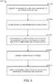
- FIG. 5 illustrates a flow diagram of one embodiment of a method 500 for controlling an uninterruptible power supply 190 of an electrical power system according to the present disclosure.
- the method 500 can include converting an AC power at a line-side converter 168 to a DC power for a DC link 136, at block 502.
- the method 500 also includes storing power from the DC link 136 in the uninterruptible power supply 190, at block 504.
- the ultracapacitor cells 194 may be charged with DC voltage from the power supply 236.
- the method 500 also includes periodically performing a health check on a rate of decay of a power storage element (e.g., the ultrcapacitor cells 194) in the uninterruptible power supply 194 with health check circuitry 192, at block 506.
- a power storage element e.g., the ultrcapacitor cells 194
- the health check may be performed as described with reference to FIG. 4 .
- performing the health check on the rate of decay can include coupling the power storage element 194 to a resistance of known value (e.g., a power resistor) and measuring the rate of decay 404over time. Then, the measured rate of decay can be compared against a set of tolerance decay bands 402, 406, or at least one of the tolerance decay bands 406.
- a resistance of known value e.g., a power resistor
- the method 500 further includes sensing a first condition in the AC power, at block 508, and, disabling the health check in response to sensing the first condition, at block 510.
- the method 500 also includes disabling the health check circuitry 192 in response to sensing the first condition.
- the first condition may include a full or partial power failure at any phase of the 3-phase power buses illustrated in FIG. 1 .
- the first condition is sensed at a first phase of a power bus.
- an uninterruptible power supply may be integrated with an electrical power system.
- the uninterruptible power supply may include a health check circuit that periodically verifies the health of a power storage element, or elements, contained therein.
- the health check circuit and associated functions may be disabled and disabled using a health check disable component, such as a relay, to ensure power is always supplied to a control system of the electrical power system during a power failure.
- Example embodiments of a wind turbine, a control system for a wind turbine, and methods of controlling a wind turbine are described above in detail.
- the methods, wind turbine, and control system are not limited to the specific embodiments described herein, but rather, components of the wind turbine and/or the control system and/or steps of the methods may be utilized independently and separately from other components and/or steps described herein.
- the control system and methods may also be used in combination with other wind turbine power systems and methods, and are not limited to practice with only the power system as described herein.
- the exemplary embodiment can be implemented and utilized in connection with many other wind turbine or power system applications, such as solar power systems and energy storage systems.
Landscapes
- Engineering & Computer Science (AREA)
- Power Engineering (AREA)
- Physics & Mathematics (AREA)
- General Physics & Mathematics (AREA)
- Business, Economics & Management (AREA)
- Emergency Management (AREA)
- Life Sciences & Earth Sciences (AREA)
- Sustainable Development (AREA)
- Sustainable Energy (AREA)
- Chemical & Material Sciences (AREA)
- Combustion & Propulsion (AREA)
- Mechanical Engineering (AREA)
- General Engineering & Computer Science (AREA)
- Control Of Eletrric Generators (AREA)
- Inverter Devices (AREA)
Claims (15)
- Elektrisches Energiesystem, das mit einem Stromnetz verbunden ist, umfassend:einen Generator, der einen Stator und einen Rotor umfasst, wobei der Stator über einen Statorstrompfad mit dem Stromnetz verbunden ist;einen Stromwandler, der mit einem Rotorbus des Rotors gekoppelt ist; ein Steuersystem, das eine oder mehrere Steuervorrichtungen umfasst, wobei die eine oder die mehreren Steuervorrichtungen zum Betreiben des Stromwandlers zum Bereitstellen eines Wechselstromsignals für den Rotorbus konfiguriert sind; undeine unterbrechungsfreie Stromversorgung, umfassend:ein Energiespeicherelement, das zum Empfangen und Speichern von elektrischem Strom konfiguriert ist und zum Versorgen des Steuersystems während eines Stromausfalls mit Strom konfiguriert ist; undeine Integritätsüberprüfungsschaltung, die zum Verifizieren des Integritätsstatus des Energiespeicherelements konfiguriert ist, wobei die Integritätsüberprüfungsschaltung eine Integritätsüberprüfungsdeaktivierungskomponente umfasst, die zum Deaktivieren der Integritätsüberprüfungsschaltung während des Stromausfalls konfiguriert ist.
- Elektrisches Energiesystem nach Anspruch 1, wobei die unterbrechungsfreie Stromversorgung ferner einen Stromausfallsensor umfasst, der zum Erfassen eines Stromausfallzustands an mindestens einer Phase des Rotorbusses konfiguriert ist.
- Elektrisches Energiesystem nach Anspruch 2, wobei das Steuersystem zum Anweisen der unterbrechungsfreien Stromversorgung zum Versorgen des Steuersystems mit Strom während des Stromausfalls konfiguriert ist.
- Elektrisches Energiesystem nach einem der vorstehenden Ansprüche, wobei das Energiespeicherelement mindestens einen Ultrakondensator umfasst.
- Elektrisches Energiesystem nach Anspruch 4, wobei der mindestens eine Ultrakondensator eine Speicherkapazität von mindestens 300 Farad umfasst.
- Elektrisches Energiesystem nach einem der vorstehenden Ansprüche, wobei das Energiespeicherelement umfasst:eine Bank von Ultrakondensatoren, die in Reihe gekoppelt sind; undeine Vielzahl von Ausgleichswiderständen, die mit der Bank von Ultrakondensatoren gekoppelt sind, wobei die Vielzahl von Ausgleichswiderständen zum Verteilen von Spannungsungleichgewichten über die Bank von Ultrakondensatoren konfiguriert ist.
- Elektrisches Energiesystem nach Anspruch 6, wobei jeder Ausgleichswiderstand aus der Vielzahl von Ausgleichswiderständen über einen einzelnen Ultrakondensator aus der Bank von Ultrakondensatoren gekoppelt ist.
- Elektrisches Energiesystem nach einem der vorstehenden Ansprüche, wobei das Steuersystem ferner zum Überwachen der unterbrechungsfreien Stromversorgung über eine Spannungsteilerschaltung konfiguriert ist, die mit dem Energiespeicherelement gekoppelt ist.
- Verfahren zum Betreiben einer unterbrechungsfreien Stromversorgung für ein doppelt gespeistes Induktionsgeneratorsystem, wobei das Verfahren umfasst:Umwandeln einer AC-Leistung an einem netzseitigen Wandler in eine DC-Leistung für einen DC-Zwischenkreis;Speichern von Energie in der unterbrechungsfreien Stromversorgung;Durchführen einer Integritätsüberprüfung einer Abklingrate eines Energiespeicherelements in der unterbrechungsfreien Stromversorgung mit einer Integritätsüberprüfungsschaltung;Erfassen eines Stromausfalls in der AC-Leistung; undDeaktivieren der Integritätsüberprüfung als Reaktion auf das Erfassen des Stromausfalls.
- Verfahren nach Anspruch 9, ferner umfassend das Deaktivieren der Integritätsüberprüfungsschaltung als Reaktion auf das Erfassen des Stromausfalls.
- Verfahren nach den Ansprüchen 9-10, wobei das Durchführen der Integritätsüberprüfung der Abklingrate umfasst:Koppeln des Energiespeicherelements mit einem Widerstand eines bekannten Werts; undMessen der Abklingrate über die Zeit.
- Verfahren nach Anspruch 11, wobei das Durchführen der Integritätsüberprüfung der Abklingrate ferner das Vergleichen der gemessenen Abklingrate mit einem Satz von Toleranzabklingbändern umfasst.
- Windturbinensystem, umfassend:einen Generator, der einen Stator und einen Rotor umfasst, wobei der Stator über einen Statorstrompfad mit dem Stromnetz verbunden ist;einen Stromwandler, umfassend einen netzseitigen Wandler, der über einen Wandlerstrompfad mit dem Stromnetz gekoppelt ist, und einen rotorseitigen Wandler, der über einen DC-Zwischenkreis mit einem Rotorbus des Rotors und dem netzseitigen Wandler gekoppelt ist;ein Steuersystem, das eine oder mehrere Steuervorrichtungen umfasst, wobei die eine oder die mehreren Steuervorrichtungen zum Betreiben des rotorseitigen Wandlers zum Bereitstellen des Wechselstromsignals für den Rotorbus konfiguriert sind; undeine unterbrechungsfreie Stromversorgung, umfassend:ein Energiespeicherelement, das zum Empfangen und Speichern von elektrischem Strom konfiguriert ist und zum Versorgen des Steuersystems während eines Stromausfalls mit Strom konfiguriert ist; undeine Integritätsüberprüfungsschaltung, die zum Verifizieren eines Integritätsstatus des Energiespeicherelements konfiguriert ist und eine Integritätsüberprüfungsdeaktivierungskomponente umfasst, die zum Deaktivieren der Integritätsüberprüfungsschaltung während des Stromausfalls konfiguriert ist.
- Windturbinensystem nach Anspruch 13, wobei die unterbrechungsfreie Stromversorgung ferner einen Stromausfallsensor umfasst, der zum Erfassen eines Stromausfallzustands an mindestens einer Phase des Rotorbusses konfiguriert ist.
- Windturbinensystem nach Anspruch 14, wobei der Stromausfallsensor zum Anweisen der unterbrechungsfreien Stromversorgung konfiguriert ist, das Steuersystem während des Stromausfalls mit Strom zu versorgen.
Applications Claiming Priority (1)
| Application Number | Priority Date | Filing Date | Title |
|---|---|---|---|
| US16/144,409 US10998760B2 (en) | 2018-09-27 | 2018-09-27 | System and method for controlling uninterruptible power supply of electrical power systems |
Publications (2)
| Publication Number | Publication Date |
|---|---|
| EP3629440A1 EP3629440A1 (de) | 2020-04-01 |
| EP3629440B1 true EP3629440B1 (de) | 2021-09-22 |
Family
ID=68084639
Family Applications (1)
| Application Number | Title | Priority Date | Filing Date |
|---|---|---|---|
| EP19200163.4A Active EP3629440B1 (de) | 2018-09-27 | 2019-09-27 | System und verfahren zur steuerung einer unterbrechungsfreien stromversorgung von elektrischen energiesystemen |
Country Status (5)
| Country | Link |
|---|---|
| US (1) | US10998760B2 (de) |
| EP (1) | EP3629440B1 (de) |
| CN (1) | CN110957753A (de) |
| DK (1) | DK3629440T3 (de) |
| ES (1) | ES2902140T3 (de) |
Families Citing this family (10)
| Publication number | Priority date | Publication date | Assignee | Title |
|---|---|---|---|---|
| US10826297B2 (en) * | 2018-11-06 | 2020-11-03 | General Electric Company | System and method for wind power generation and transmission in electrical power systems |
| CN112196739B (zh) * | 2020-10-10 | 2022-04-26 | 国电联合动力技术有限公司 | 一种风力发电机组不间断电源智能调控系统和方法 |
| US11996236B2 (en) * | 2021-05-26 | 2024-05-28 | Eaton Intelligent Power Limited | Current balancing apparatus and methods for parallel connected circuit breakers |
| JP2025506565A (ja) | 2022-02-08 | 2025-03-11 | フラワー ターバインズ インコーポレイテッド | 流体タービン群を動作させるためのシステムおよび方法 |
| CN119452163A (zh) | 2022-04-12 | 2025-02-14 | 马克·丹尼尔·法博 | 用于操作流体涡轮机集群的系统和方法 |
| WO2023201214A2 (en) * | 2022-04-12 | 2023-10-19 | Mark Daniel Farb | Systems and methods for operating a cluster of fluid turbines |
| WO2024050317A1 (en) | 2022-08-28 | 2024-03-07 | Flower Turbines, Inc. | Systems and methods for operating a cluster of fluid turbines |
| CN119895139A (zh) | 2022-09-18 | 2025-04-25 | 花卉涡轮机股份有限公司 | 用于涡轮轴的套筒 |
| WO2024151908A2 (en) | 2023-01-15 | 2024-07-18 | Mark Daniel Farb | Systems and methods for fluid turbine operations |
| CN121311675A (zh) | 2023-04-09 | 2026-01-09 | 花卉涡轮机股份有限公司 | 流体涡轮机操作系统和方法 |
Family Cites Families (36)
| Publication number | Priority date | Publication date | Assignee | Title |
|---|---|---|---|---|
| US5886503A (en) * | 1996-05-29 | 1999-03-23 | Peco Ii, Inc. | Back-up battery management apparatus for charging and testing individual battery cells in a string of battery cells |
| US6316917B1 (en) | 1999-03-09 | 2001-11-13 | Asahi Glass Company, Limited | Apparatus having plural electric double layer capacitors and method for adjusting voltages of the capacitors |
| JP2003032908A (ja) | 2001-07-19 | 2003-01-31 | Nisshinbo Ind Inc | キャパシタ組電池、その制御方法、その制御装置及び自動車用蓄電システム |
| US6921985B2 (en) | 2003-01-24 | 2005-07-26 | General Electric Company | Low voltage ride through for wind turbine generators |
| DE10327344A1 (de) * | 2003-06-16 | 2005-01-27 | Repower Systems Ag | Windenergieanlage |
| US20060018073A1 (en) | 2004-07-23 | 2006-01-26 | Maxwell Technologies, Inc. | Active protection against transients |
| JP4738206B2 (ja) * | 2006-02-28 | 2011-08-03 | 三菱重工業株式会社 | 風力発電システム、及びその制御方法 |
| EP2044326B1 (de) | 2006-07-06 | 2018-08-22 | Acciona Windpower, S.A. | Systeme, verfahren und vorrichtungen für eine windturbinensteuerung |
| US8049364B2 (en) * | 2007-06-04 | 2011-11-01 | Electrikus, Inc. | Back-up power system |
| DE102007039697A1 (de) * | 2007-08-22 | 2009-02-26 | Woodward Seg Gmbh & Co. Kg | Verfahren und Vorrichtung zur Kompensation von Schwingungseffekten bei Netzunsymmetrie bei einer doppeltgespeisten Asynchronmaschine |
| EP2221934A4 (de) * | 2007-12-14 | 2012-01-18 | Mitsubishi Heavy Ind Ltd | Aerogeneratorsystem |
| AU2007362448B2 (en) * | 2007-12-14 | 2012-12-20 | Mitsubishi Heavy Industries, Ltd. | Wind power generation system and operation control method therof |
| US7952232B2 (en) | 2008-03-13 | 2011-05-31 | General Electric Company | Wind turbine energy storage and frequency control |
| JP4834691B2 (ja) * | 2008-05-09 | 2011-12-14 | 株式会社日立製作所 | 風力発電システム |
| ES2345645B1 (es) * | 2008-06-09 | 2011-07-13 | GAMESA INNOVATION & TECHNOLOGY, S.L. | Instalacion de energia eolica y procedimiento de modificacion del paso de pala en una instalacion de energia eolica. |
| BRPI0822536A2 (pt) * | 2008-10-16 | 2015-06-23 | Mitsubishi Heavy Ind Ltd | Sistema de gerador de turbina eólica, e, método para controlar o mesmo |
| CA2763646C (en) | 2009-05-29 | 2015-11-17 | Toshiba Mitsubishi-Electric Industrial Systems Corporation | Uninterruptible power supply device |
| US8482151B2 (en) * | 2009-07-02 | 2013-07-09 | Electrical Power Worx Corp. | Auxiliary power systems and methods thereof |
| US9494138B2 (en) * | 2009-08-14 | 2016-11-15 | Vestas Wind Systems A/S | Variable speed wind turbine, and a method for operating the variable speed wind turbine during a power imbalance event |
| CN101692502B (zh) * | 2009-09-25 | 2011-08-17 | 深圳市航盛电子股份有限公司 | 电池管理系统 |
| SE536419C2 (sv) | 2010-06-02 | 2013-10-15 | Balansering av superkondensatorer | |
| DE102011079360A1 (de) | 2011-07-19 | 2013-01-24 | Sb Limotive Company Ltd. | Vorrichtung und Verfahren zur Messung einer maximalen Zellspannung |
| US9077204B2 (en) * | 2011-07-20 | 2015-07-07 | Inventus Holdings, Llc | Dispatchable renewable energy generation, control and storage facility |
| CN104024821B (zh) * | 2011-12-28 | 2016-05-18 | 本田技研工业株式会社 | 车辆诊断系统、车辆诊断方法和车辆 |
| US9587628B2 (en) * | 2012-01-17 | 2017-03-07 | General Electric Company | Method for operating a wind turbine |
| US9966758B2 (en) | 2012-06-11 | 2018-05-08 | Panduit Corp. | Capacitor-based UPS |
| DK3004637T4 (da) * | 2013-06-04 | 2021-02-15 | Gen Electric | Fremgangsmåder til at drive vindmøllesystem med dynamisk bremse |
| CH708109B1 (de) | 2013-08-01 | 2014-12-15 | Chypsotech Gmbh Michael Müller | Unterbrechungsfreie Stromversorgung (USV) für elektronische Geräte. |
| US9337685B2 (en) * | 2013-12-23 | 2016-05-10 | General Electric Company | Optimized filter for battery energy storage on alternate energy systems |
| US9667057B2 (en) * | 2014-06-18 | 2017-05-30 | General Electric Company | System and method for protecting a power converter during an adverse voltage event |
| CN105548899B (zh) * | 2016-01-04 | 2019-03-01 | 朱建强 | 一种机器人的电池管理方法及装置 |
| US10003214B2 (en) | 2016-03-21 | 2018-06-19 | General Electric Company | Battery management system |
| EP3226380B1 (de) | 2016-03-31 | 2022-04-06 | Konica Minolta Business Solutions Europe GmbH | Ununterbrechbare stromversorgung |
| US20180191236A1 (en) * | 2017-01-05 | 2018-07-05 | General Electric Company | Filter Device for Power Converters with Silicon Carbide Mosfets |
| CN107317386A (zh) * | 2017-06-21 | 2017-11-03 | 江南大学 | 基于风光互补的土壤墒情监测系统供能 |
| US11283275B2 (en) * | 2018-03-07 | 2022-03-22 | Isac Tabib | Smart uninterruptible power supply and method |
-
2018
- 2018-09-27 US US16/144,409 patent/US10998760B2/en active Active
-
2019
- 2019-09-27 EP EP19200163.4A patent/EP3629440B1/de active Active
- 2019-09-27 ES ES19200163T patent/ES2902140T3/es active Active
- 2019-09-27 DK DK19200163.4T patent/DK3629440T3/da active
- 2019-09-27 CN CN201910922057.XA patent/CN110957753A/zh active Pending
Also Published As
| Publication number | Publication date |
|---|---|
| US20200106295A1 (en) | 2020-04-02 |
| ES2902140T3 (es) | 2022-03-25 |
| CN110957753A (zh) | 2020-04-03 |
| DK3629440T3 (da) | 2022-01-03 |
| US10998760B2 (en) | 2021-05-04 |
| EP3629440A1 (de) | 2020-04-01 |
Similar Documents
| Publication | Publication Date | Title |
|---|---|---|
| EP3629440B1 (de) | System und verfahren zur steuerung einer unterbrechungsfreien stromversorgung von elektrischen energiesystemen | |
| CN103370873B (zh) | 能够在应急模式下操作的变桨距电机驱动电路 | |
| US9667057B2 (en) | System and method for protecting a power converter during an adverse voltage event | |
| US9337685B2 (en) | Optimized filter for battery energy storage on alternate energy systems | |
| US10519933B2 (en) | Method of operating a wind turbine system including an energy storage system | |
| US9447772B2 (en) | Systems and methods for increasing wind turbine power output | |
| EP2876769B1 (de) | System und Verfahren zum Betrieb eines Stromerzeugungssystems in einem Energiespeicherungs-/Entlade- oder dynamischen Bremsmodus | |
| US10523088B2 (en) | Energy storage system for doubly fed induction generator | |
| EP3004637A1 (de) | Verfahren zum betreiben eines windturbinensystems mit dynamischer bremse | |
| US20170145989A1 (en) | Wind turbine auxiliary circuit control | |
| US20150249414A1 (en) | Wind turbine systems and methods for operating the same | |
| US10855079B1 (en) | System and method for reducing oscillations in a renewable energy power system | |
| CN102804592B (zh) | 风能设备的叶片调整系统的紧急调整装置 | |
| EP3617497B1 (de) | System und verfahren zur erhöhung der mechanischen trägheit des rotors einer windturbine zum unterstützen des netzes während eines frequenzereignisses | |
| WO2018231422A2 (en) | Methods for operating electrical power systems | |
| CN112994545B (zh) | 用于缓解设备失效的功率转换器的选择性撬棍响应 | |
| EP3487066B1 (de) | System und verfahren zum betreiben eines doppelt gespeisten induktionsgeneratorsystems zur reduzierung von oberschwingungen | |
| CN112443455B (zh) | 在低风速期间操作风力涡轮功率系统的系统和方法 | |
| JP5852441B2 (ja) | 風力発電システム |
Legal Events
| Date | Code | Title | Description |
|---|---|---|---|
| PUAI | Public reference made under article 153(3) epc to a published international application that has entered the european phase |
Free format text: ORIGINAL CODE: 0009012 |
|
| STAA | Information on the status of an ep patent application or granted ep patent |
Free format text: STATUS: THE APPLICATION HAS BEEN PUBLISHED |
|
| AK | Designated contracting states |
Kind code of ref document: A1 Designated state(s): AL AT BE BG CH CY CZ DE DK EE ES FI FR GB GR HR HU IE IS IT LI LT LU LV MC MK MT NL NO PL PT RO RS SE SI SK SM TR |
|
| AX | Request for extension of the european patent |
Extension state: BA ME |
|
| STAA | Information on the status of an ep patent application or granted ep patent |
Free format text: STATUS: REQUEST FOR EXAMINATION WAS MADE |
|
| 17P | Request for examination filed |
Effective date: 20200916 |
|
| RBV | Designated contracting states (corrected) |
Designated state(s): AL AT BE BG CH CY CZ DE DK EE ES FI FR GB GR HR HU IE IS IT LI LT LU LV MC MK MT NL NO PL PT RO RS SE SI SK SM TR |
|
| GRAP | Despatch of communication of intention to grant a patent |
Free format text: ORIGINAL CODE: EPIDOSNIGR1 |
|
| STAA | Information on the status of an ep patent application or granted ep patent |
Free format text: STATUS: GRANT OF PATENT IS INTENDED |
|
| INTG | Intention to grant announced |
Effective date: 20201123 |
|
| GRAJ | Information related to disapproval of communication of intention to grant by the applicant or resumption of examination proceedings by the epo deleted |
Free format text: ORIGINAL CODE: EPIDOSDIGR1 |
|
| STAA | Information on the status of an ep patent application or granted ep patent |
Free format text: STATUS: REQUEST FOR EXAMINATION WAS MADE |
|
| GRAP | Despatch of communication of intention to grant a patent |
Free format text: ORIGINAL CODE: EPIDOSNIGR1 |
|
| STAA | Information on the status of an ep patent application or granted ep patent |
Free format text: STATUS: GRANT OF PATENT IS INTENDED |
|
| INTC | Intention to grant announced (deleted) | ||
| INTG | Intention to grant announced |
Effective date: 20210428 |
|
| GRAS | Grant fee paid |
Free format text: ORIGINAL CODE: EPIDOSNIGR3 |
|
| GRAA | (expected) grant |
Free format text: ORIGINAL CODE: 0009210 |
|
| STAA | Information on the status of an ep patent application or granted ep patent |
Free format text: STATUS: THE PATENT HAS BEEN GRANTED |
|
| AK | Designated contracting states |
Kind code of ref document: B1 Designated state(s): AL AT BE BG CH CY CZ DE DK EE ES FI FR GB GR HR HU IE IS IT LI LT LU LV MC MK MT NL NO PL PT RO RS SE SI SK SM TR |
|
| REG | Reference to a national code |
Ref country code: GB Ref legal event code: FG4D |
|
| REG | Reference to a national code |
Ref country code: DE Ref legal event code: R096 Ref document number: 602019007824 Country of ref document: DE |
|
| REG | Reference to a national code |
Ref country code: IE Ref legal event code: FG4D |
|
| REG | Reference to a national code |
Ref country code: CH Ref legal event code: EP Ref country code: AT Ref legal event code: REF Ref document number: 1433061 Country of ref document: AT Kind code of ref document: T Effective date: 20211015 |
|
| REG | Reference to a national code |
Ref country code: DK Ref legal event code: T3 Effective date: 20211221 |
|
| REG | Reference to a national code |
Ref country code: LT Ref legal event code: MG9D |
|
| REG | Reference to a national code |
Ref country code: NL Ref legal event code: MP Effective date: 20210922 |
|
| PG25 | Lapsed in a contracting state [announced via postgrant information from national office to epo] |
Ref country code: HR Free format text: LAPSE BECAUSE OF FAILURE TO SUBMIT A TRANSLATION OF THE DESCRIPTION OR TO PAY THE FEE WITHIN THE PRESCRIBED TIME-LIMIT Effective date: 20210922 Ref country code: NO Free format text: LAPSE BECAUSE OF FAILURE TO SUBMIT A TRANSLATION OF THE DESCRIPTION OR TO PAY THE FEE WITHIN THE PRESCRIBED TIME-LIMIT Effective date: 20211222 Ref country code: LT Free format text: LAPSE BECAUSE OF FAILURE TO SUBMIT A TRANSLATION OF THE DESCRIPTION OR TO PAY THE FEE WITHIN THE PRESCRIBED TIME-LIMIT Effective date: 20210922 Ref country code: BG Free format text: LAPSE BECAUSE OF FAILURE TO SUBMIT A TRANSLATION OF THE DESCRIPTION OR TO PAY THE FEE WITHIN THE PRESCRIBED TIME-LIMIT Effective date: 20211222 Ref country code: FI Free format text: LAPSE BECAUSE OF FAILURE TO SUBMIT A TRANSLATION OF THE DESCRIPTION OR TO PAY THE FEE WITHIN THE PRESCRIBED TIME-LIMIT Effective date: 20210922 Ref country code: RS Free format text: LAPSE BECAUSE OF FAILURE TO SUBMIT A TRANSLATION OF THE DESCRIPTION OR TO PAY THE FEE WITHIN THE PRESCRIBED TIME-LIMIT Effective date: 20210922 Ref country code: SE Free format text: LAPSE BECAUSE OF FAILURE TO SUBMIT A TRANSLATION OF THE DESCRIPTION OR TO PAY THE FEE WITHIN THE PRESCRIBED TIME-LIMIT Effective date: 20210922 |
|
| REG | Reference to a national code |
Ref country code: AT Ref legal event code: MK05 Ref document number: 1433061 Country of ref document: AT Kind code of ref document: T Effective date: 20210922 |
|
| PG25 | Lapsed in a contracting state [announced via postgrant information from national office to epo] |
Ref country code: LV Free format text: LAPSE BECAUSE OF FAILURE TO SUBMIT A TRANSLATION OF THE DESCRIPTION OR TO PAY THE FEE WITHIN THE PRESCRIBED TIME-LIMIT Effective date: 20210922 Ref country code: GR Free format text: LAPSE BECAUSE OF FAILURE TO SUBMIT A TRANSLATION OF THE DESCRIPTION OR TO PAY THE FEE WITHIN THE PRESCRIBED TIME-LIMIT Effective date: 20211223 |
|
| REG | Reference to a national code |
Ref country code: ES Ref legal event code: FG2A Ref document number: 2902140 Country of ref document: ES Kind code of ref document: T3 Effective date: 20220325 |
|
| PG25 | Lapsed in a contracting state [announced via postgrant information from national office to epo] |
Ref country code: AT Free format text: LAPSE BECAUSE OF FAILURE TO SUBMIT A TRANSLATION OF THE DESCRIPTION OR TO PAY THE FEE WITHIN THE PRESCRIBED TIME-LIMIT Effective date: 20210922 |
|
| REG | Reference to a national code |
Ref country code: BE Ref legal event code: MM Effective date: 20210930 |
|
| PG25 | Lapsed in a contracting state [announced via postgrant information from national office to epo] |
Ref country code: IS Free format text: LAPSE BECAUSE OF FAILURE TO SUBMIT A TRANSLATION OF THE DESCRIPTION OR TO PAY THE FEE WITHIN THE PRESCRIBED TIME-LIMIT Effective date: 20220122 Ref country code: SK Free format text: LAPSE BECAUSE OF FAILURE TO SUBMIT A TRANSLATION OF THE DESCRIPTION OR TO PAY THE FEE WITHIN THE PRESCRIBED TIME-LIMIT Effective date: 20210922 Ref country code: RO Free format text: LAPSE BECAUSE OF FAILURE TO SUBMIT A TRANSLATION OF THE DESCRIPTION OR TO PAY THE FEE WITHIN THE PRESCRIBED TIME-LIMIT Effective date: 20210922 Ref country code: PT Free format text: LAPSE BECAUSE OF FAILURE TO SUBMIT A TRANSLATION OF THE DESCRIPTION OR TO PAY THE FEE WITHIN THE PRESCRIBED TIME-LIMIT Effective date: 20220124 Ref country code: PL Free format text: LAPSE BECAUSE OF FAILURE TO SUBMIT A TRANSLATION OF THE DESCRIPTION OR TO PAY THE FEE WITHIN THE PRESCRIBED TIME-LIMIT Effective date: 20210922 Ref country code: NL Free format text: LAPSE BECAUSE OF FAILURE TO SUBMIT A TRANSLATION OF THE DESCRIPTION OR TO PAY THE FEE WITHIN THE PRESCRIBED TIME-LIMIT Effective date: 20210922 Ref country code: EE Free format text: LAPSE BECAUSE OF FAILURE TO SUBMIT A TRANSLATION OF THE DESCRIPTION OR TO PAY THE FEE WITHIN THE PRESCRIBED TIME-LIMIT Effective date: 20210922 Ref country code: CZ Free format text: LAPSE BECAUSE OF FAILURE TO SUBMIT A TRANSLATION OF THE DESCRIPTION OR TO PAY THE FEE WITHIN THE PRESCRIBED TIME-LIMIT Effective date: 20210922 Ref country code: AL Free format text: LAPSE BECAUSE OF FAILURE TO SUBMIT A TRANSLATION OF THE DESCRIPTION OR TO PAY THE FEE WITHIN THE PRESCRIBED TIME-LIMIT Effective date: 20210922 |
|
| REG | Reference to a national code |
Ref country code: DE Ref legal event code: R097 Ref document number: 602019007824 Country of ref document: DE |
|
| PG25 | Lapsed in a contracting state [announced via postgrant information from national office to epo] |
Ref country code: MC Free format text: LAPSE BECAUSE OF FAILURE TO SUBMIT A TRANSLATION OF THE DESCRIPTION OR TO PAY THE FEE WITHIN THE PRESCRIBED TIME-LIMIT Effective date: 20210922 |
|
| PG25 | Lapsed in a contracting state [announced via postgrant information from national office to epo] |
Ref country code: LU Free format text: LAPSE BECAUSE OF NON-PAYMENT OF DUE FEES Effective date: 20210927 Ref country code: IE Free format text: LAPSE BECAUSE OF NON-PAYMENT OF DUE FEES Effective date: 20210927 Ref country code: BE Free format text: LAPSE BECAUSE OF NON-PAYMENT OF DUE FEES Effective date: 20210930 |
|
| PLBE | No opposition filed within time limit |
Free format text: ORIGINAL CODE: 0009261 |
|
| STAA | Information on the status of an ep patent application or granted ep patent |
Free format text: STATUS: NO OPPOSITION FILED WITHIN TIME LIMIT |
|
| 26N | No opposition filed |
Effective date: 20220623 |
|
| PG25 | Lapsed in a contracting state [announced via postgrant information from national office to epo] |
Ref country code: SI Free format text: LAPSE BECAUSE OF FAILURE TO SUBMIT A TRANSLATION OF THE DESCRIPTION OR TO PAY THE FEE WITHIN THE PRESCRIBED TIME-LIMIT Effective date: 20210922 Ref country code: FR Free format text: LAPSE BECAUSE OF NON-PAYMENT OF DUE FEES Effective date: 20211122 |
|
| PG25 | Lapsed in a contracting state [announced via postgrant information from national office to epo] |
Ref country code: IT Free format text: LAPSE BECAUSE OF FAILURE TO SUBMIT A TRANSLATION OF THE DESCRIPTION OR TO PAY THE FEE WITHIN THE PRESCRIBED TIME-LIMIT Effective date: 20210922 |
|
| REG | Reference to a national code |
Ref country code: CH Ref legal event code: PL |
|
| PG25 | Lapsed in a contracting state [announced via postgrant information from national office to epo] |
Ref country code: CY Free format text: LAPSE BECAUSE OF FAILURE TO SUBMIT A TRANSLATION OF THE DESCRIPTION OR TO PAY THE FEE WITHIN THE PRESCRIBED TIME-LIMIT Effective date: 20210922 |
|
| P01 | Opt-out of the competence of the unified patent court (upc) registered |
Effective date: 20230530 |
|
| PG25 | Lapsed in a contracting state [announced via postgrant information from national office to epo] |
Ref country code: SM Free format text: LAPSE BECAUSE OF FAILURE TO SUBMIT A TRANSLATION OF THE DESCRIPTION OR TO PAY THE FEE WITHIN THE PRESCRIBED TIME-LIMIT Effective date: 20210922 Ref country code: LI Free format text: LAPSE BECAUSE OF NON-PAYMENT OF DUE FEES Effective date: 20220930 Ref country code: HU Free format text: LAPSE BECAUSE OF FAILURE TO SUBMIT A TRANSLATION OF THE DESCRIPTION OR TO PAY THE FEE WITHIN THE PRESCRIBED TIME-LIMIT; INVALID AB INITIO Effective date: 20190927 Ref country code: CH Free format text: LAPSE BECAUSE OF NON-PAYMENT OF DUE FEES Effective date: 20220930 |
|
| REG | Reference to a national code |
Ref country code: DE Ref legal event code: R081 Ref document number: 602019007824 Country of ref document: DE Owner name: GENERAL ELECTRIC RENOVABLES ESPANA, S.L., ES Free format text: FORMER OWNER: GENERAL ELECTRIC COMPANY, SCHENECTADY, NY, US Ref country code: DE Ref legal event code: R082 Ref document number: 602019007824 Country of ref document: DE Ref country code: DE Ref legal event code: R082 Ref document number: 602019007824 Country of ref document: DE Representative=s name: ZIMMERMANN & PARTNER PATENTANWAELTE MBB, DE |
|
| REG | Reference to a national code |
Ref country code: DE Ref legal event code: R082 Ref document number: 602019007824 Country of ref document: DE Representative=s name: ZIMMERMANN & PARTNER PATENTANWAELTE MBB, DE |
|
| PG25 | Lapsed in a contracting state [announced via postgrant information from national office to epo] |
Ref country code: MK Free format text: LAPSE BECAUSE OF FAILURE TO SUBMIT A TRANSLATION OF THE DESCRIPTION OR TO PAY THE FEE WITHIN THE PRESCRIBED TIME-LIMIT Effective date: 20210922 |
|
| GBPC | Gb: european patent ceased through non-payment of renewal fee |
Effective date: 20230927 |
|
| PG25 | Lapsed in a contracting state [announced via postgrant information from national office to epo] |
Ref country code: TR Free format text: LAPSE BECAUSE OF FAILURE TO SUBMIT A TRANSLATION OF THE DESCRIPTION OR TO PAY THE FEE WITHIN THE PRESCRIBED TIME-LIMIT Effective date: 20210922 |
|
| PG25 | Lapsed in a contracting state [announced via postgrant information from national office to epo] |
Ref country code: GB Free format text: LAPSE BECAUSE OF NON-PAYMENT OF DUE FEES Effective date: 20230927 |
|
| PG25 | Lapsed in a contracting state [announced via postgrant information from national office to epo] |
Ref country code: GB Free format text: LAPSE BECAUSE OF NON-PAYMENT OF DUE FEES Effective date: 20230927 |
|
| REG | Reference to a national code |
Ref country code: ES Ref legal event code: PC2A Owner name: GENERAL ELECTRIC RENOVABLES ESPANA S.L. Effective date: 20240809 |
|
| PG25 | Lapsed in a contracting state [announced via postgrant information from national office to epo] |
Ref country code: MT Free format text: LAPSE BECAUSE OF FAILURE TO SUBMIT A TRANSLATION OF THE DESCRIPTION OR TO PAY THE FEE WITHIN THE PRESCRIBED TIME-LIMIT Effective date: 20210922 |
|
| PGFP | Annual fee paid to national office [announced via postgrant information from national office to epo] |
Ref country code: DK Payment date: 20250820 Year of fee payment: 7 Ref country code: DE Payment date: 20250820 Year of fee payment: 7 |
|
| PGFP | Annual fee paid to national office [announced via postgrant information from national office to epo] |
Ref country code: ES Payment date: 20251001 Year of fee payment: 7 |