EP3629450A1 - Moteur électrique à refroidissement par liquide - Google Patents
Moteur électrique à refroidissement par liquide Download PDFInfo
- Publication number
- EP3629450A1 EP3629450A1 EP18197448.6A EP18197448A EP3629450A1 EP 3629450 A1 EP3629450 A1 EP 3629450A1 EP 18197448 A EP18197448 A EP 18197448A EP 3629450 A1 EP3629450 A1 EP 3629450A1
- Authority
- EP
- European Patent Office
- Prior art keywords
- cooling
- electric motor
- cooling channel
- sprayed
- layer
- Prior art date
- Legal status (The legal status is an assumption and is not a legal conclusion. Google has not performed a legal analysis and makes no representation as to the accuracy of the status listed.)
- Withdrawn
Links
- 238000001816 cooling Methods 0.000 title claims abstract description 152
- 239000007788 liquid Substances 0.000 title description 9
- 238000004519 manufacturing process Methods 0.000 claims abstract description 40
- 238000000034 method Methods 0.000 claims abstract description 30
- 239000000126 substance Substances 0.000 claims abstract description 27
- 229910052782 aluminium Inorganic materials 0.000 claims abstract description 13
- XAGFODPZIPBFFR-UHFFFAOYSA-N aluminium Chemical compound [Al] XAGFODPZIPBFFR-UHFFFAOYSA-N 0.000 claims abstract description 13
- 229910001220 stainless steel Inorganic materials 0.000 claims abstract description 13
- 239000010935 stainless steel Substances 0.000 claims abstract description 13
- 239000000654 additive Substances 0.000 claims abstract description 11
- 230000000996 additive effect Effects 0.000 claims abstract description 11
- 238000005507 spraying Methods 0.000 claims abstract description 10
- 230000008569 process Effects 0.000 claims abstract description 6
- RYGMFSIKBFXOCR-UHFFFAOYSA-N Copper Chemical compound [Cu] RYGMFSIKBFXOCR-UHFFFAOYSA-N 0.000 claims description 5
- 229910052802 copper Inorganic materials 0.000 claims description 5
- 239000010949 copper Substances 0.000 claims description 5
- 238000003754 machining Methods 0.000 claims description 5
- 229910052751 metal Inorganic materials 0.000 claims description 3
- 239000002184 metal Substances 0.000 claims description 3
- 239000000843 powder Substances 0.000 claims description 3
- 239000000463 material Substances 0.000 abstract description 8
- XLYOFNOQVPJJNP-UHFFFAOYSA-N water Substances O XLYOFNOQVPJJNP-UHFFFAOYSA-N 0.000 description 4
- 238000005260 corrosion Methods 0.000 description 3
- 230000007797 corrosion Effects 0.000 description 3
- 230000000694 effects Effects 0.000 description 3
- 239000002826 coolant Substances 0.000 description 2
- 239000012530 fluid Substances 0.000 description 2
- 239000000110 cooling liquid Substances 0.000 description 1
- 238000010586 diagram Methods 0.000 description 1
- 230000017525 heat dissipation Effects 0.000 description 1
- 230000006872 improvement Effects 0.000 description 1
- 230000003993 interaction Effects 0.000 description 1
- 238000003801 milling Methods 0.000 description 1
- 230000009467 reduction Effects 0.000 description 1
- 238000007789 sealing Methods 0.000 description 1
- 125000006850 spacer group Chemical group 0.000 description 1
- 239000007921 spray Substances 0.000 description 1
- 230000007704 transition Effects 0.000 description 1
Images

Classifications
-
- H—ELECTRICITY
- H02—GENERATION; CONVERSION OR DISTRIBUTION OF ELECTRIC POWER
- H02K—DYNAMO-ELECTRIC MACHINES
- H02K15/00—Processes or apparatus specially adapted for manufacturing, assembling, maintaining or repairing of dynamo-electric machines
- H02K15/14—Casings; Enclosures; Supports
-
- B—PERFORMING OPERATIONS; TRANSPORTING
- B29—WORKING OF PLASTICS; WORKING OF SUBSTANCES IN A PLASTIC STATE IN GENERAL
- B29C—SHAPING OR JOINING OF PLASTICS; SHAPING OF MATERIAL IN A PLASTIC STATE, NOT OTHERWISE PROVIDED FOR; AFTER-TREATMENT OF THE SHAPED PRODUCTS, e.g. REPAIRING
- B29C64/00—Additive manufacturing, i.e. manufacturing of three-dimensional [3D] objects by additive deposition, additive agglomeration or additive layering, e.g. by 3D printing, stereolithography or selective laser sintering
- B29C64/10—Processes of additive manufacturing
- B29C64/188—Processes of additive manufacturing involving additional operations performed on the added layers, e.g. smoothing, grinding or thickness control
-
- B—PERFORMING OPERATIONS; TRANSPORTING
- B29—WORKING OF PLASTICS; WORKING OF SUBSTANCES IN A PLASTIC STATE IN GENERAL
- B29C—SHAPING OR JOINING OF PLASTICS; SHAPING OF MATERIAL IN A PLASTIC STATE, NOT OTHERWISE PROVIDED FOR; AFTER-TREATMENT OF THE SHAPED PRODUCTS, e.g. REPAIRING
- B29C64/00—Additive manufacturing, i.e. manufacturing of three-dimensional [3D] objects by additive deposition, additive agglomeration or additive layering, e.g. by 3D printing, stereolithography or selective laser sintering
- B29C64/40—Structures for supporting 3D objects during manufacture and intended to be sacrificed after completion thereof
-
- H—ELECTRICITY
- H02—GENERATION; CONVERSION OR DISTRIBUTION OF ELECTRIC POWER
- H02K—DYNAMO-ELECTRIC MACHINES
- H02K41/00—Propulsion systems in which a rigid body is moved along a path due to dynamo-electric interaction between the body and a magnetic field travelling along the path
- H02K41/02—Linear motors; Sectional motors
-
- H—ELECTRICITY
- H02—GENERATION; CONVERSION OR DISTRIBUTION OF ELECTRIC POWER
- H02K—DYNAMO-ELECTRIC MACHINES
- H02K5/00—Casings; Enclosures; Supports
- H02K5/04—Casings or enclosures characterised by the shape, form or construction thereof
- H02K5/20—Casings or enclosures characterised by the shape, form or construction thereof with channels or ducts for flow of cooling medium
- H02K5/203—Casings or enclosures characterised by the shape, form or construction thereof with channels or ducts for flow of cooling medium specially adapted for liquids, e.g. cooling jackets
Definitions
- the invention relates to an electric motor with at least one cooling channel.
- Electric motors can be designed, for example, as a linear motor or as a rotary motor.
- such motors are provided with liquid cooling, usually water cooling, the water cooling dissipating heat from the motor.
- the linear motor has a primary part and a secondary part, the primary part and the secondary part being movable in a direction of movement of the linear motor.
- the linear motor has cooling consisting of cooling channels, the individual sheets of the laminated core of the primary part and / or secondary part being designed such that when the individual sheets of the laminated core are joined together, the cooling channels are formed.
- the invention is based on the object of producing an electric motor with liquid cooling with improved heat transfer and improved cooling performance in a simple and inexpensive manner and also of specifying such a method for producing such an electric motor.
- an electric motor with at least one cooling duct, the cooling duct being generated by means of a generative manufacturing process in that the cooling duct is formed by a first sprayed-on layer into which a groove corresponding to the cooling duct is milled, which groove forms a groove that forms the cooling duct water-soluble substance is filled, which is then sealed with a second sprayed-on layer, so that after rinsing the water-soluble substance of the cooling channel for cooling the electric motor is formed.
- a cooling duct is generated by means of a generative manufacturing process in that the cooling duct is formed by a first sprayed-on layer, into which a groove corresponding to the cooling duct is milled, which groove corresponds to the Cooling channel-forming water-soluble substance is filled, which is then closed with a second sprayed-on layer, so that after rinsing out the water-soluble substance, the cooling channel for cooling the electric motor is formed.
- a cooler in particular for a linear motor, the cooler having at least one cooling duct, the cooling duct being generated by means of a generative manufacturing process in that the cooling duct is formed by a first sprayed-on layer into which a groove corresponding to the cooling duct is formed is milled, which is filled with a water-soluble substance forming the cooling channel, which is then closed with a second sprayed-on layer, so that after the water-soluble substance is rinsed out, the cooling channel for cooling the electric motor is formed.
- the invention is based on the finding that, in the case of electric motors conventionally cooled via cooling pipes or cooling coils, liquid cooling, usually water cooling, usually only allows a small contact area for structural reasons, so that cooling of the electric motor is not optimal.
- a so-called precision cooler which is also liquid-cooled, is often used for the thermal shielding of the so-called active part.
- the cooling pipes attached there usually only have a limited cooling capacity due to the constructionally rather problematic heat transfer.
- a cooling duct produced with a generative manufacturing process enables optimal heat transfer that can be specifically adapted to the respective thermal conditions.
- the cooling channel is formed by a first sprayed-on layer, into which a groove corresponding to the cooling channel is then milled. This is then filled with a water-soluble substance forming the cooling channel, which in the next step is sealed again with a second sprayed-on layer. After rinsing out the water-soluble substance, an optimal cooling channel for cooling the electric motor is created.
- cooling channels of this type can be introduced into a separate precision cooler, while in the case of rotary motors, the cooling channels are provided in a corresponding manner in the housing of the motor at the points to be cooled.
- cooling duct is manufactured by means of the additive manufacturing process of cold gas spraying.
- MPA Metal Powder Application Technique
- Stainless steel, aluminum or copper are preferably used as materials for the first and / or the second sprayed-on layer.
- these materials are dimensionally stable and, at the same time, corrosion-resistant and therefore durable.
- Advantageous applications are in all liquid-cooled, in particular water-cooled electric motors, the electric motor being a liquid-cooled linear motor or a liquid-cooled rotary motor.
- a low-cost and safe supply of the coolant to the cooling channel can be made even safer and simpler by integrally forming connecting pieces on the cooling channel, which are also produced in a generative manufacturing process.
- Optimal cooling results can be achieved by designing the first and / or the second sprayed-on layer in terms of shape and properties in such a way that the largest possible contact area is created.
- a familiar and proven design of a linear motor is made possible by the fact that the electric motor is a liquid-cooled linear motor with a primary part and at least one secondary part and the cooling duct is arranged in a separate cooler arranged on the primary part.
- a familiar and proven design of a rotary motor is made possible by the fact that the electric motor is a liquid-cooled rotary motor, the cooling channel being produced in a die-cast housing by the combination of additive and machining processes.
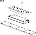
- FIG. 1 shows an exploded view of a linear motor 1 with a cooler 2 for liquid cooling.
- the linear motor 1 consists of a primary part 3 and one or more secondary parts 4.
- the cooler 5 is provided, which has connecting pieces 6 and 7 for supplying a cooling liquid.
- the cooling channel 5 between the inlet and the outlet via the connecting pieces 6 and 7 is visualized with a dashed line.
- the cooling channel is not in a conventional manner (compare FIG 2 ) consists of an attached cooling tube, which has only a limited cooling effect, but that the cooling channel 5 is generated by means of a generative manufacturing process, whereby for ensuring a connection that is as fluid as possible and thus for one improved heat transfer and an improved cooling capacity of the cooling channel 5 is generated by the use of the additive method cold gas spraying.
- the cooling channel 5 is formed by a first sprayed-on layer, in particular made of stainless steel or aluminum, into which a groove corresponding to the cooling channel 5 is milled, which is then filled with a water-soluble substance using the same method and then again with stainless steel or aluminum using a second sprayed layer is closed. In the last manufacturing step, the water-soluble substance is then rinsed out, so that the cooling channel 5 is created.
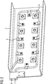
- FIG 2 shows a view of a cooler 2 for a linear motor from below.
- the cooler 2 consists of cooling channels 5 with connecting pieces 6 and 7 for supplying liquid cooling.
- the cooling tubes forming the cooling duct 5 are fastened to the base body of the cooler 2 by means of a holding device. Spacers 9 are also provided, which serve as distance compensation.
- cooler 2 for example around a precision cooler for a linear motor, as has been used up to now.
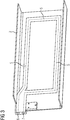
- FIG 3 shows a view of a first exemplary embodiment of a cooler 2 with additively manufactured cooling duct 5 for a linear motor from below.
- the ones already related to FIG 2 introduced reference numerals used.
- the illustrated embodiment of a known cooler is that in FIG 3 shown cooler 2, ie the cooling channel 5 generated by means of a generative manufacturing process.
- a first sprayed-on layer is formed, into which a groove corresponding to the cooling channel 5 is milled (cf. FIG 6 ), which is filled with a water-soluble substance using the same process and then closed again with stainless steel or aluminum.
- the last step in the manufacturing process is the water-soluble substance rinsed out so that the cooling channel 5 is formed.
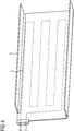
- FIG 4 shows a further embodiment of a cooler 2 with additively manufactured cooling duct 5 for a linear motor from below, as shown, for example, in interaction with a linear motor FIG. 1 is used.
- the dashed line visualizes a cooling channel 5, which compared to the in FIG 3
- the illustrated embodiment shows several meandering cooling coils. This ensures a further improvement in heat dissipation in the areas to be cooled. Due to the meandering shape, the coolant can flow without problems and thus ensure safe and optimal cooling.
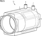
- FIG 5 shows a housing of a rotary motor 10, with additively manufactured cooling duct 5.
- the cooling duct 5 in turn has connecting pieces 6 and 7 for supplying liquid cooling, in particular water.
- Rotary motor 10 shown or its housing consists in that the cooling channel 5 or the cooling channels 5 is in turn generated in the housing by means of a generative method, namely the generative method "cold gas spraying".
- a first sprayed-on layer in particular made of stainless steel, aluminum or copper, is applied in a first production step, into which a groove is then milled in a second production step or introduced using another method.
- this groove is then filled with a water-soluble substance, onto which a second sprayed-on layer made of stainless steel, aluminum or copper is then sprayed in a fourth manufacturing step, while in a fifth manufacturing step, the water-soluble substance is again rinsed out of the cooling channel 5 thus created .
- the method presented enables a tightly closed and filigree cooling channel structure if required. In addition, no subsequent sealing or redirection measures are required. Due to the filigree cooling structure, the cooling effect can be optimized and the cooling channels 5 can also be designed in terms of strength in such a way that an excessive reduction in strength is prevented by either too large channels.
- the cooling channels 5 can also be formed axially meandering in the housing with a rotary motor in this embodiment.
- the axial stiffness compared to circumferential cooling channels can thus be significantly increased by the axial rib structure.
- the cooling channels 5 can additionally also be configured with a corrosion-resistant material, so that a corrosion-insensitive cooling channel is formed in the material.
- the connecting pieces 6, 7 can also be molded onto the cooling channel in a generative manufacturing process.
- FIG 6 shows a schematic diagram of a section of a motor part of an electric motor with additively manufactured cooling duct.
- FIG 6 thus once again illustrates the manufacturing process of the cooling duct 5.
- a first sprayed-on layer applied by means of the generative method of cold gas spraying, is applied to a base material 14 of the engine part or the radiator part, and this first sprayed-on layer 11 is then used in the second manufacturing step 21 introduced a groove, for example by means of a machining process such as milling.
- this groove is then filled with a water-soluble substance 12 again using the additive method of cold gas spraying.
- the water-soluble substance 12 and the first sprayed-on layer 11 are again provided with a second sprayed-on layer 13 using the cold gas spray process, so that the in FIG 6 shown basic structure for a cooling channel 5 arises.
- the water-soluble substance 12 is then rinsed out of the cooler 2 or the engine part, so that the cooling duct 5, as in FIGS Figures 3 to 5 shown, generative arises.
- the invention thus relates to an electric motor 1, 10 with at least one cooling duct, the cooling duct 5 being generated by means of a generative manufacturing process.
- the cooling channel 5 is generated by the use of the additive cold gas spraying method.
- the cooling channel is formed by a sprayed-on layer of stainless steel or aluminum, into which a groove corresponding to the cooling channel 5 is milled, which is filled with a water-soluble substance using the same method and then closed again with stainless steel or aluminum. In the last manufacturing step, the water-soluble substance is rinsed out, so that the cooling channel 5 is created.
- the method can be used both with liquid-cooled linear motors and with liquid-cooled rotary motors.
Landscapes
- Engineering & Computer Science (AREA)
- Power Engineering (AREA)
- Manufacturing & Machinery (AREA)
- Motor Or Generator Cooling System (AREA)
Priority Applications (1)
| Application Number | Priority Date | Filing Date | Title |
|---|---|---|---|
| EP18197448.6A EP3629450A1 (fr) | 2018-09-28 | 2018-09-28 | Moteur électrique à refroidissement par liquide |
Applications Claiming Priority (1)
| Application Number | Priority Date | Filing Date | Title |
|---|---|---|---|
| EP18197448.6A EP3629450A1 (fr) | 2018-09-28 | 2018-09-28 | Moteur électrique à refroidissement par liquide |
Publications (1)
| Publication Number | Publication Date |
|---|---|
| EP3629450A1 true EP3629450A1 (fr) | 2020-04-01 |
Family
ID=63708207
Family Applications (1)
| Application Number | Title | Priority Date | Filing Date |
|---|---|---|---|
| EP18197448.6A Withdrawn EP3629450A1 (fr) | 2018-09-28 | 2018-09-28 | Moteur électrique à refroidissement par liquide |
Country Status (1)
| Country | Link |
|---|---|
| EP (1) | EP3629450A1 (fr) |
Cited By (1)
| Publication number | Priority date | Publication date | Assignee | Title |
|---|---|---|---|---|
| WO2022258735A1 (fr) * | 2021-06-11 | 2022-12-15 | Valeo Equipements Electriques Moteur | Carter machine électrique tournante et machine électrique tournante |
Citations (8)
| Publication number | Priority date | Publication date | Assignee | Title |
|---|---|---|---|---|
| DE102007020057A1 (de) | 2007-04-27 | 2008-11-13 | Siemens Ag | Linearmotor mit integrierter Kühlung |
| US20130011562A1 (en) * | 2011-05-26 | 2013-01-10 | Solidscape, Inc. | Method for fabricating three dimensional models |
| DE102015219763A1 (de) * | 2015-10-13 | 2017-04-13 | Robert Bosch Gmbh | Einteiliges kühlsystem für elektrische maschineund verfahren zur herstellung eines kühlsystems für eine elektrische maschine |
| DE102016203945A1 (de) * | 2016-03-10 | 2017-09-14 | Siemens Aktiengesellschaft | Statoreinrichtung für eine elektrische Maschine und Verfahren zu deren Herstellung |
| DE102016122612A1 (de) * | 2016-11-23 | 2018-05-24 | Kessler energy GmbH | Motorkomponente, Primärteil und Linearmotor |
| EP3337019A1 (fr) * | 2016-12-16 | 2018-06-20 | Etel S. A.. | Part primaire comprenant une plaque de refroidissement |
| US20180194076A1 (en) * | 2017-01-12 | 2018-07-12 | Voxei8, Inc. | Techniques for hybrid additive and substractive manufacturing |
| EP3364525A1 (fr) * | 2017-02-21 | 2018-08-22 | Siemens Aktiengesellschaft | Composants des machines électriques formés par des processus de fabrication additive et procédés de fabrication correspondants |
-
2018
- 2018-09-28 EP EP18197448.6A patent/EP3629450A1/fr not_active Withdrawn
Patent Citations (8)
| Publication number | Priority date | Publication date | Assignee | Title |
|---|---|---|---|---|
| DE102007020057A1 (de) | 2007-04-27 | 2008-11-13 | Siemens Ag | Linearmotor mit integrierter Kühlung |
| US20130011562A1 (en) * | 2011-05-26 | 2013-01-10 | Solidscape, Inc. | Method for fabricating three dimensional models |
| DE102015219763A1 (de) * | 2015-10-13 | 2017-04-13 | Robert Bosch Gmbh | Einteiliges kühlsystem für elektrische maschineund verfahren zur herstellung eines kühlsystems für eine elektrische maschine |
| DE102016203945A1 (de) * | 2016-03-10 | 2017-09-14 | Siemens Aktiengesellschaft | Statoreinrichtung für eine elektrische Maschine und Verfahren zu deren Herstellung |
| DE102016122612A1 (de) * | 2016-11-23 | 2018-05-24 | Kessler energy GmbH | Motorkomponente, Primärteil und Linearmotor |
| EP3337019A1 (fr) * | 2016-12-16 | 2018-06-20 | Etel S. A.. | Part primaire comprenant une plaque de refroidissement |
| US20180194076A1 (en) * | 2017-01-12 | 2018-07-12 | Voxei8, Inc. | Techniques for hybrid additive and substractive manufacturing |
| EP3364525A1 (fr) * | 2017-02-21 | 2018-08-22 | Siemens Aktiengesellschaft | Composants des machines électriques formés par des processus de fabrication additive et procédés de fabrication correspondants |
Cited By (2)
| Publication number | Priority date | Publication date | Assignee | Title |
|---|---|---|---|---|
| WO2022258735A1 (fr) * | 2021-06-11 | 2022-12-15 | Valeo Equipements Electriques Moteur | Carter machine électrique tournante et machine électrique tournante |
| FR3124038A1 (fr) * | 2021-06-11 | 2022-12-16 | Valeo Equipements Electriques Moteur | Carter machine électrique tournante et machine électrique tournante |
Similar Documents
| Publication | Publication Date | Title |
|---|---|---|
| DE3542185C2 (fr) | ||
| EP2204628B1 (fr) | Échangeur de chaleur en plastique | |
| DE102017220297B4 (de) | Wärmetauscher | |
| EP3489603A1 (fr) | Echangeur de chaleur | |
| DE102016225521A1 (de) | Kühlmantel-Gehäuse, insbesondere für eine elektrische Maschine | |
| EP3056847B1 (fr) | Dispositif et procede destines a la thermoregulation d'un corps | |
| DE102011076140A1 (de) | Kühlmantel für Elektromotor | |
| DE102009037548A1 (de) | Gehäuseteil für ein Getriebe und Verfahren zur Herstellung | |
| DE2016991A1 (fr) | ||
| DE102006044785A1 (de) | Anordnung zur Kühlung einer flüssigkeitsgekühlten elektrischen Maschine mit Korrosionsschutz durch Hochtemperaturverzinken | |
| EP3629450A1 (fr) | Moteur électrique à refroidissement par liquide | |
| DE2928710C2 (de) | Strombegrenzungsvorrichtung | |
| DE60212568T2 (de) | Raketentriebwerksglied und verfahren zur herstellung eines raketentriebwerksglied | |
| DE102015219763A1 (de) | Einteiliges kühlsystem für elektrische maschineund verfahren zur herstellung eines kühlsystems für eine elektrische maschine | |
| DE102019218885B4 (de) | Stützstift für Katalysator mit elektrischer Heizscheibe | |
| DE102018106341A1 (de) | Zylinderrohr für eine Hubkolbenmaschine | |
| DE2303699A1 (de) | Fluessigkeitsgekuehltes auslassventil fuer eine brennkraftmaschine und herstellungsverfahren | |
| DE69113588T2 (de) | Zylinder für Einzel- oder Doppelrollenstranggiessen. | |
| DE102013002097B4 (de) | Verfahren zum Herstellen eines kühlbaren Werkzeugteils für ein Formwerkzeug zum Warmumformen und/oder Presshärten, sowie hiermit hergestelltes Formwerkzeug | |
| DE2856762A1 (de) | Stromzufuehrungseinrichtung fuer die rotorwicklung einer elektrischen maschine | |
| EP3754702A1 (fr) | Procédé de fabrication d'un dissipateur thermique | |
| DE202022104389U1 (de) | Effiziente Wärmeabfuhr über Gleitlager einer Drehanode | |
| DE102018212654A1 (de) | Kühlung einer elektrischen Maschine | |
| DE102018206138A1 (de) | Gehäuse eines Elektromotors | |
| DE2156959A1 (fr) |
Legal Events
| Date | Code | Title | Description |
|---|---|---|---|
| PUAI | Public reference made under article 153(3) epc to a published international application that has entered the european phase |
Free format text: ORIGINAL CODE: 0009012 |
|
| STAA | Information on the status of an ep patent application or granted ep patent |
Free format text: STATUS: THE APPLICATION HAS BEEN PUBLISHED |
|
| AK | Designated contracting states |
Kind code of ref document: A1 Designated state(s): AL AT BE BG CH CY CZ DE DK EE ES FI FR GB GR HR HU IE IS IT LI LT LU LV MC MK MT NL NO PL PT RO RS SE SI SK SM TR |
|
| AX | Request for extension of the european patent |
Extension state: BA ME |
|
| STAA | Information on the status of an ep patent application or granted ep patent |
Free format text: STATUS: THE APPLICATION IS DEEMED TO BE WITHDRAWN |
|
| 18D | Application deemed to be withdrawn |
Effective date: 20201002 |