EP3629510B1 - Procédé de transmission de données, dispositif, équipement côté réseau, et équipement d'utilisateur - Google Patents
Procédé de transmission de données, dispositif, équipement côté réseau, et équipement d'utilisateur Download PDFInfo
- Publication number
- EP3629510B1 EP3629510B1 EP18817379.3A EP18817379A EP3629510B1 EP 3629510 B1 EP3629510 B1 EP 3629510B1 EP 18817379 A EP18817379 A EP 18817379A EP 3629510 B1 EP3629510 B1 EP 3629510B1
- Authority
- EP
- European Patent Office
- Prior art keywords
- data transmission
- srs
- sri
- layer
- srs resources
- Prior art date
- Legal status (The legal status is an assumption and is not a legal conclusion. Google has not performed a legal analysis and makes no representation as to the accuracy of the status listed.)
- Active
Links
Images


Classifications
-
- H—ELECTRICITY
- H04—ELECTRIC COMMUNICATION TECHNIQUE
- H04L—TRANSMISSION OF DIGITAL INFORMATION, e.g. TELEGRAPHIC COMMUNICATION
- H04L5/00—Arrangements affording multiple use of the transmission path
- H04L5/003—Arrangements for allocating sub-channels of the transmission path
- H04L5/0048—Allocation of pilot signals, i.e. of signals known to the receiver
- H04L5/0051—Allocation of pilot signals, i.e. of signals known to the receiver of dedicated pilots, i.e. pilots destined for a single user or terminal
-
- H—ELECTRICITY
- H04—ELECTRIC COMMUNICATION TECHNIQUE
- H04W—WIRELESS COMMUNICATION NETWORKS
- H04W72/00—Local resource management
- H04W72/20—Control channels or signalling for resource management
- H04W72/23—Control channels or signalling for resource management in the downlink direction of a wireless link, i.e. towards a terminal
-
- H—ELECTRICITY
- H04—ELECTRIC COMMUNICATION TECHNIQUE
- H04B—TRANSMISSION
- H04B7/00—Radio transmission systems, i.e. using radiation field
- H04B7/02—Diversity systems; Multi-antenna system, i.e. transmission or reception using multiple antennas
- H04B7/04—Diversity systems; Multi-antenna system, i.e. transmission or reception using multiple antennas using two or more spaced independent antennas
- H04B7/0404—Diversity systems; Multi-antenna system, i.e. transmission or reception using multiple antennas using two or more spaced independent antennas the mobile station comprising multiple antennas, e.g. to provide uplink diversity
-
- H—ELECTRICITY
- H04—ELECTRIC COMMUNICATION TECHNIQUE
- H04B—TRANSMISSION
- H04B7/00—Radio transmission systems, i.e. using radiation field
- H04B7/02—Diversity systems; Multi-antenna system, i.e. transmission or reception using multiple antennas
- H04B7/04—Diversity systems; Multi-antenna system, i.e. transmission or reception using multiple antennas using two or more spaced independent antennas
- H04B7/06—Diversity systems; Multi-antenna system, i.e. transmission or reception using multiple antennas using two or more spaced independent antennas at the transmitting station
- H04B7/0613—Diversity systems; Multi-antenna system, i.e. transmission or reception using multiple antennas using two or more spaced independent antennas at the transmitting station using simultaneous transmission
- H04B7/0615—Diversity systems; Multi-antenna system, i.e. transmission or reception using multiple antennas using two or more spaced independent antennas at the transmitting station using simultaneous transmission of weighted versions of same signal
- H04B7/0617—Diversity systems; Multi-antenna system, i.e. transmission or reception using multiple antennas using two or more spaced independent antennas at the transmitting station using simultaneous transmission of weighted versions of same signal for beam forming
-
- H—ELECTRICITY
- H04—ELECTRIC COMMUNICATION TECHNIQUE
- H04B—TRANSMISSION
- H04B7/00—Radio transmission systems, i.e. using radiation field
- H04B7/02—Diversity systems; Multi-antenna system, i.e. transmission or reception using multiple antennas
- H04B7/04—Diversity systems; Multi-antenna system, i.e. transmission or reception using multiple antennas using two or more spaced independent antennas
- H04B7/06—Diversity systems; Multi-antenna system, i.e. transmission or reception using multiple antennas using two or more spaced independent antennas at the transmitting station
- H04B7/0613—Diversity systems; Multi-antenna system, i.e. transmission or reception using multiple antennas using two or more spaced independent antennas at the transmitting station using simultaneous transmission
- H04B7/0615—Diversity systems; Multi-antenna system, i.e. transmission or reception using multiple antennas using two or more spaced independent antennas at the transmitting station using simultaneous transmission of weighted versions of same signal
- H04B7/0619—Diversity systems; Multi-antenna system, i.e. transmission or reception using multiple antennas using two or more spaced independent antennas at the transmitting station using simultaneous transmission of weighted versions of same signal using feedback from receiving side
- H04B7/0621—Feedback content
- H04B7/063—Parameters other than those covered in groups H04B7/0623 - H04B7/0634, e.g. channel matrix rank or transmit mode selection
-
- H—ELECTRICITY
- H04—ELECTRIC COMMUNICATION TECHNIQUE
- H04L—TRANSMISSION OF DIGITAL INFORMATION, e.g. TELEGRAPHIC COMMUNICATION
- H04L5/00—Arrangements affording multiple use of the transmission path
- H04L5/0091—Signalling for the administration of the divided path, e.g. signalling of configuration information
- H04L5/0094—Indication of how sub-channels of the path are allocated
-
- H—ELECTRICITY
- H04—ELECTRIC COMMUNICATION TECHNIQUE
- H04W—WIRELESS COMMUNICATION NETWORKS
- H04W72/00—Local resource management
- H04W72/04—Wireless resource allocation
- H04W72/044—Wireless resource allocation based on the type of the allocated resource
- H04W72/046—Wireless resource allocation based on the type of the allocated resource the resource being in the space domain, e.g. beams
-
- H—ELECTRICITY
- H04—ELECTRIC COMMUNICATION TECHNIQUE
- H04L—TRANSMISSION OF DIGITAL INFORMATION, e.g. TELEGRAPHIC COMMUNICATION
- H04L5/00—Arrangements affording multiple use of the transmission path
- H04L5/0001—Arrangements for dividing the transmission path
- H04L5/0003—Two-dimensional division
- H04L5/0005—Time-frequency
- H04L5/0007—Time-frequency the frequencies being orthogonal, e.g. OFDM(A) or DMT
-
- H—ELECTRICITY
- H04—ELECTRIC COMMUNICATION TECHNIQUE
- H04L—TRANSMISSION OF DIGITAL INFORMATION, e.g. TELEGRAPHIC COMMUNICATION
- H04L5/00—Arrangements affording multiple use of the transmission path
- H04L5/0091—Signalling for the administration of the divided path, e.g. signalling of configuration information
- H04L5/0096—Indication of changes in allocation
Definitions
- the present disclosure relates to the field of communication technology, and more particularly to a data transmission method, and a data transmission device.
- MIMO Multiple Input Multiple Output
- LTE Long Term Evolution
- LTE-A LTE-Advanced
- OFDM Orthogonal Frequency Division Multiplexing
- the LTE Rel-8 supports up to 4 layers of MIMO transmission.
- Rel-9 focuses on the enhancement of Multi-User MIMO (MU-MIMO) technology.
- Transmission Mode (TM)-8 MU-MIMO transmission can support up to 4 Downlink (DL) data layers.
- the Rel-10 introduces 8 antenna ports to further improve the spatial resolution of channel state information, and further extend the transmission capability of Single-User MIMO (SU-MIMO) to up to 8 data layers.
- the Rel-13 and Rel-14 introduce the Frequency Division-MIMO (FD-MIMO) technology to support port 32 to achieve full dimensions and vertical beam forming.
- FD-MIMO Frequency Division-MIMO
- large-scale antenna technology is introduced into the mobile communication system.
- fully digital large-scale antennas can have up to 128/256/512 antenna units and up to 128/256/512 transceiver units and each antenna unit connects to a transceiver unit.
- pilot signals up to 128/256/512 antenna ports
- the terminal measures channel state information and feeds back.
- an antenna array with up to 32/64 antenna units can also be configured.
- a huge beam forming gain is obtained to make up for the signal attenuation caused by path loss.
- path loss makes the coverage of wireless signal extremely limited.
- the coverage of the wireless signal can be extended to a practical range.
- Beam forming can be implemented by simulating beam forming and digital-analog hybrid beam forming, both of which require to adjust weights of the analog beam forming of the transmitting end and receiving end, so that the beams formed by them can be aligned with the opposite end of the communication.
- For DL transmission the weight of the beam forming transmitted by the base station side and weight of the beam forming received by the terminal side require to be adjusted.
- For Uplink (UL) transmission the weight of the beam forming transmitted by the terminal side and weight of the beam forming received by the base station side require to be adjusted.
- the weight of the beam forming is usually obtained by transmitting training signals.
- the base station transmits the DL beam training signal
- the terminal measures the DL beam training signal, selects the best beam transmitted by the base station, and feeds back the information related to beam to the base station, meanwhile selects the corresponding best received beam and saves it locally.
- the UE equipped with multiple transmitting antennas can perform UL beam forming, but in the existing mode, the UE is impossible to determine the specific UL data transmission implementation process via the UL Sounding Reference Signal (SRS) resources indicated by the received Transmission Reference Point (TRP).
- SRS Sounding Reference Signal
- EP 3 493 418 A1 was filed before the priority date of the present invention and published after that. Therefore, this document is not relevant to the question of inventive step. It discloses a data sending method, a signaling sending method, an apparatus, and a system, and relates to the communications field.
- EP3493418A1 is prior art according to Article 54(3) EPC.
- An objective of the present disclosure is to provide a data transmission method, a data transmission device, a network side device and UE to implement the UL data transmission indicated by the TRP.
- an embodiment of the present disclosure provides a data transmission method, applied to a first device, including:
- the method further includes:
- Each layer of the UL data transmission has a corresponding relationship with at least one SRS resource indicated by the SRI.
- a UL beam forming matrix adopted by each layer of the UL data transmission is consistent with a UL beam forming matrix of SRS resources corresponding to the layer of the UL data transmission.
- the corresponding relationship between the each layer of the UL data transmission and the at least one SRS resource in the L SRS resources is indicated by a Layer-to-SRI mapping Indicator (LSI) and the method further includes: transmitting the LSI to the second device.
- LSI Layer-to-SRI mapping Indicator
- the corresponding relationship between the each layer of the UL data transmission and the at least one SRS resource in the L SRS resources is indicated by the SRI.
- the number L of SRS resources indicated by the SRI is consistent with the layer number of the UL data transmission or codeword number.
- a k-th SRS resource indicated by the SRI has a corresponding relationship with a k-th layer of the UL data transmission or k-th codeword, 1 ⁇ k ⁇ L, k is an integer.
- an embodiment of the present disclosure provides a data transmission method, applied to a second device, including:
- the method further includes:
- Each layer of the UL data transmission has a corresponding relationship with at least one SRS resource indicated by the SRI.
- a UL beam forming matrix adopted by each layer of the UL data transmission is consistent with a UL beam forming matrix of SRS resources corresponding to the layer of the UL data transmission.
- the corresponding relationship between the each layer of the UL data transmission and the at least one SRS resource in the L SRS resources is indicated by a Layer-to-SRI mapping Indicator (LSI); and the method further includes:
- the corresponding relationship between the each layer of the UL data transmission and the at least one SRS resource in the L SRS resources is indicated by the SRI; performing the UL data transmission according to the SRI includes:
- the number L of SRS resources indicated by the SRI is consistent with layer number of the UL data transmission or codeword number.
- a k-th SRS resource indicated by the SRI has a corresponding relationship with a k-th layer of the UL data transmission or k-th codeword, 1 ⁇ k ⁇ L, k is an integer.
- an embodiment of the present disclosure further provides a data transmission device, applied to a first device, including:
- the device further includes:
- Each layer of the UL data transmission has a corresponding relationship with at least one SRS resource indicated by the SRI.
- a UL beam forming matrix adopted by each layer of the UL data transmission is consistent with a UL beam forming matrix of SRS resources corresponding to the layer of the UL data transmission.
- the corresponding relationship between the each layer of the UL data transmission and the at least one SRS resource in the L SRS resources is indicated by a Layer-to-SRI mapping Indicator (LSI); and the device further includes: a fourth transmission module, configured to transmit the LSI to the second device.
- LSI Layer-to-SRI mapping Indicator
- the corresponding relationship between the each layer of the UL data transmission and the at least one SRS resource in the L SRS resources is indicated by the SRI.
- the number L of SRS resources indicated by the SRI is consistent with layer number of the UL data transmission or codeword number.
- a k-th SRS resource indicated by the SRI has a corresponding relationship with a k-th layer of the UL data transmission or k-th codeword, 1 ⁇ k ⁇ L, k is an integer.
- an embodiment of the present disclosure further provides a data transmission device, applied to a second device, including:
- the device further includes:
- Each layer of the UL data transmission has a corresponding relationship with at least one SRS resource indicated by the SRI.
- a UL beam forming matrix adopted by each layer of the UL data transmission is consistent with a UL beam forming matrix of SRS resources corresponding to the layer of the UL data transmission.
- the corresponding relationship between the each layer of the UL data transmission and the at least one SRS resource in the L SRS resources is indicated by a Layer-to-SRI mapping Indicator (LSI); and the device further includes:
- the UL data transmission module includes:
- the number L of SRS resources indicated by the SRI is consistent with the layer number of the UL data transmission or codeword number.
- a k-th SRS resource indicated by the SRI has a corresponding relationship with a k-th layer of the UL data transmission or k-th codeword, 1 ⁇ k ⁇ L, k is an integer.
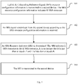
- the data transmission method in embodiments of the present disclosure first transmits the SRS resource configuration information, which indicates K SRS resources and is configured for the second device, to the second device.
- the second device receives the SRS resource configuration information, and then transmits the SRS through K SRS resources according to the SRS resource configuration information.
- the first device optimally selects L SRS resources from K SRS resources and determines the SRI indicating the L SRS resources.
- the first device transmits the SRI to the second device to inform the second device of the SRS resources of UL data transmission. Therefore, after receiving the SRI, the second device can use the L optimal SRS resources to complete the UL data transmission, so as to solve the problem that the existing mode cannot determine the specific implementation process of UL data transmission.
- embodiments of the present disclosure provide a data transmission method.
- the UL data transmission is implemented via instructing the UE to use preferred SRS resources in the originally configured SRS resources.
- embodiments of the present disclosure provide a data transmission method, applied to a first device, including:
- the first device first transmits the SRS resource configuration information, which indicates K SRS resources and is configured for the second device, to the second device.
- the second device receives the SRS resource configuration information, and then transmits the SRS through K SRS resources according to the SRS resource configuration information.
- the first device optimally selects L SRS resources from K SRS resources and determines the SRI indicating the L SRS resources.
- the first device transmits the SRI to the second device to inform the second device of the SRS resources of UL data transmission. Therefore, after receiving the SRI, the second device can use the L optimal SRS resources to complete the UL data transmission, so as to solve the problem that the existing mode cannot determine the specific implementation process of UL data transmission.
- the first device can select L SRS resources (1 ⁇ L ⁇ K) and determine SRI based on the measurement of signal quality of the K SRS resources. Specifically, the first device selects L SRS resources, such as L SRS resources (target SRS resources) with the highest receiving quality, according to the preset mode of the system. Preferably, L is greater than or equal to 1.
- the SRI value determined by the first device can include L SRS resources, that is, each SRI value corresponds to one target SRS resource.
- the SRI can be transmitted through the Downlink Control Information (DCI).
- DCI Downlink Control Information
- the value of the SRI can be a variable and therefore the payload of the DCI is variable or a fixed value determined by the maximum number of the SRIs.
- the actual number of SRI values indicated in the DCI can be equal to or less than the maximum number of SRI values.
- Some SRI values (if not specified) in the DCI field can be retained.
- the SRI in the DCI is a fixed s-bit information field and each state of the s-bit information field is configured as being associated with a set of SRS resources by a high-level signaling.
- Table 1 SRI Information 0 ⁇ SRS resource 0 ⁇ 1 ⁇ SRS resource 0 , SRS resource 1 ⁇ 2 ⁇ SRS resource 2, SRS resource 3 ⁇ 3 reserved
- the second device performs the UL data transmission and needs to know the layer number of the UL data transmission besides knowing the target SRS resource determined by the first device for it via receiving the SRI.
- the second device cannot determine the layer number of its UL data transmission and cannot complete the UL data transmission. Therefore, on the basis of the above embodiment, the data transmission method in embodiments of the present disclosure further includes:
- the first device determines the TRI corresponding to the UL data transmission of the second device and transmits the TRI to the second device, so that the second device may obtain the layer number of the UL data transmission configured by the first device for the second device in a situation that the system does not predefine the number of the layers of the UL data transmission, thereby completing the final UL data transmission.
- the TRI may be transmitted to the second device together with the SRI or both of them are separately transmitted.
- each layer of the UL data transmission has a corresponding relationship with at least one SRS resource indicated by the SRI.
- the second device can use the SRS resources indicated by the SRI to transmit the corresponding layer of the UL data transmission according to the corresponding relationship.
- a UL beam forming matrix adopted by each layer of the UL data transmission is consistent with a UL beam forming matrix of SRS resources corresponding to the layer of the UL data transmission.
- the second device may optimally select the UL beam forming matrix corresponding to the target SRS resources and definitely obtain the UL beam forming matrix of each layer of the UL data transmission according to the corresponding relationship between the at least one SRS resource in the target SRS resources and the layers of the UL data transmission.
- the corresponding layers of the UL data transmission are transmitted via the UL beam forming matrix of the L SRS resources.
- an antenna panel adopted by each layer of the UL data transmission is consistent with the antenna panel of the SRS resources corresponding to the layer of the UL data transmission.
- the second device can definitely obtain the antenna panel of each layer of the UL data transmission via the antenna panel corresponding to the optimally selected target SRS resources and the corresponding relationship between the target SRS resources and the layer of the UL data transmission.
- the layer of the UL data transmission is transmitted via the antenna panel of the L SRS resources.
- the corresponding relationship between the each layer of the UL data transmission and the at least one SRS resource in the L SRS resources is indicated by a Layer-to-SRI mapping Indicator (LSI), and the method further includes: transmitting the LSI to the second device.
- LSI Layer-to-SRI mapping Indicator
- the corresponding relationship between each layer of the UL data transmission and L SRS resources is indicated via the dedicated LSI.
- the LSI is transmitted to the second device to inform the second device, so that the second device implements the UL data transmission.
- each layer of the UL data transmission and the target SRS resource indicated by the LSI may be the indication of each layer of the UL data transmission or indication of each codeword.
- Each codeword is generated by a channel coding module and is subsequently divided into at least one layer of the UL data transmission according to a preset rule.
- the LSI is the indication of the each layer of the UL data transmission.
- the LSI is a sequence of R variables.
- R denotes the layer number of the UL data transmission.
- Each value in the R variable points to one of the L SRI values.
- the first variable represents transmitting layer-1 using the antenna panel and/or UL beam forming matrix of the SRS resource indicated by the first SRI, and transmitting layer-2 using the antenna panel and/or UL beam forming matrix of the SRS resource indicated by the second SRI.
- the LSI is the indication of each codeword.
- the LSI is a sequence of C variables.
- C denotes the codeword number of the UL data transmission.
- Each value in the C variable points to one of the L SRI values.
- the first variable represents transmitting all layers of the first codeword using the antenna panel and/or UL beam forming matrix of the SRS resource indicated by the first SRI, and transmitting all layers of the second codeword using the antenna panel and/or UL beam forming matrix of the SRS resource indicated by the second SRI.
- the corresponding relationship between the each layer of the UL data transmission and the at least one SRS resource in the L SRS resources is indicated by the SRI.
- New indicator is not required and the SRI is used to indicate the corresponding relationship between the each layer of the UL data transmission and at least one SRS resource in the L SRS resources to reduce the information transmission and improve resource utilization.
- the SRI indicates the corresponding relationship between the each layer of the UL data transmission and at least one SRS resource in the L SRS resources, specifically, the number L of the SRS resources indicated by SRI is consistent with the layer number of the UL data transmission or codeword number.
- the layer-1 is transmitted using the antenna panel and/or UL beam forming matrix of the SRS resource indicated by the first SRI, and the layer-2 is transmitted using the antenna panel and/or UL beam forming matrix of the SRS resource indicated by the second SRI.
- the k-th SRS resource indicated by the SRI has a corresponding relationship with the k-th layer or k-th codeword of the UL data transmission, 1 ⁇ k ⁇ L, k is an integer.
- the first SRS resource (first SRS resource) is used to transmit the first UL data transmission layer (the first layer of the UL data transmission), or the first SRS resource (first SRS rcsourcc) is used to transmit all layers of the UL data transmission of the first codeword (first codeword).
- the first device may be a cell base station, micro station or wireless network Wireless Fidelity (WIFI) router and other network-side devices.
- the second device can be a mobile phone, tablet or computer and other user devices, which are not listed here.
- the data transmission method in embodiments of the present disclosure first transmits the SRS resource configuration information indicating K SRS resources configured for the second device to the second device; and the second device receives the SRS resource configuration information, then transmits the SRS through K SRS resources according to the SRS resource configuration information.
- L SRS resources are preferably selected from the K SRS resources according to the SRS signal, and the SRI indicating the L SRS resources can be determined.
- the first device then transmits the SRI to the second device to inform the second device of the SRS resource for its UL data transmission.
- the second device can use the preferably-selected L SRS resources to complete the UL data transmission, so as to solve the problem that the existing mode cannot determine the specific implementation process of UL data transmission.
- embodiments of the present disclosure provide a data transmission method, applied to a second device, including:
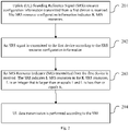
- the second device first receives the SRS resource configuration information, which is configured by the first device for the second device and is used to indicate the K SRS resources, then transmits the SRS to the first device using K SRS resources according to the SRS resource configuration information, so that after the first device receives the SRS signal, the first device preferably selects L SRS resources from the K SRS resources, determines the SRI indicating the L SRS resources and transmits the SRI to the second device. After receiving the SRI, the second device can use the preferably-selected L SRS resources to complete the UL data transmission, so as to solve the problem that the existing mode cannot determine the specific implementation process of UL data transmission.
- the method in this embodiment further includes:
- the second device may obtain the layer number of the UL data transmission determined for it by the first device via parsing the TRI to implement the final UL data transmission.
- each layer of the UL data transmission has a corresponding relationship with at least one SRS resource indicated by the SRI.
- a UL beam forming matrix adopted by each layer of the UL data transmission is consistent with a UL beam forming matrix of SRS resources corresponding to the layer of the UL data transmission.
- the method further includes:
- the second device obtains the corresponding relationship between the at least one SRS resource in the L SRS resources and each layer of the UL data transmission via parsing the LSI to implement the UL data transmission.
- the corresponding relationship between each layer of the UL data transmission and at least one SRS resource in the target SRS resources indicated by the LSI may be the indication of each layer of the UL data transmission or indication of each codeword, which is not repeated here.
- the corresponding relationship between the each layer of the UL data transmission and the at least one SRS resource in the L SRS resources is indicated by the SRI.
- the block 204 includes:
- the first device uses the SRI to indicate the corresponding relationship between at least one SRS resources in L SRS resources and each layer of the UL data transmission.
- the second device obtains the corresponding relationship between at least one SRS resources in L SRS resources and each layer of the UL data transmission via parsing the SRI and respectively transmits the layer of the UL data transmission using the L SRS rcsourccs.
- number L of the SRS resources indicated by the SRI is consistent with layer number of the UL data transmission or codeword number.
- the k-th SRS resource indicated by the SRI has a corresponding relationship with the k-th layer of the UL data transmission or the k-th codeword, 1 ⁇ k ⁇ L, k is an integer.
- the second device first receives the SRS resource configuration information, which is configured by the first device for the second device and is used to indicate K SRS resources, then transmits the SRS to the first device using K SRS resources according to the SRS resource configuration information, so that after the first device receives the SRS signal, the first device preferably selects L SRS resources from the K SRS resources, determines the SRI indicating the L SRS resources and transmits the SRI to the second device. After receiving the SRI, the second device can use the preferably-selected L SRS resources to complete the UL data transmission, so as to solve the problem that the existing mode cannot determine the specific implementation process of UL data transmission.
- the data transmission method applied to the second device in this embodiment is used to cooperate with the data transmission method applied to the first device in the above embodiment.
- the implementation mode of the data transmission method applied to the first device in the above embodiment is also suitable for this method, also can achieve the same technical effect, which is not repeated here.
- embodiments of the present disclosure further provide a data transmission device, applied to a first device, including:
- the device further includes:
- the each layer of the UL data transmission has a corresponding relationship with at least one SRS resource indicated by the SRI.
- a UL beam forming matrix adopted by the each layer of the UL data transmission is consistent with a UL beam forming matrix of SRS resources corresponding to the layer of the UL data transmission.
- the corresponding relationship between the each layer of the UL data transmission and the at least one SRS resource in the L SRS resources is indicated by the LSI, and the device further includes: a fourth transmission module, configured to transmit the LSI to the second device.
- the corresponding relationship between the each layer of the UL data transmission and the at least one SRS resource in the L SRS resources is indicated by the SRI.
- Number L of SRS resources indicated by the SRI is consistent with layer number of the UL data transmission or codeword number.
- the k-th SRS resource indicated by the SRI has a corresponding relationship with the k-th layer of the UL data transmission or k-th codeword, 1 ⁇ k ⁇ L, k is an integer.
- the data transmission device in this embodiment of the present disclosure first transmits the SRS resource configuration information indicating K SRS resources configured for the second device to the second device; and the second device receives the SRS resource configuration information, then transmits the SRS through K SRS resources according to the SRS resource configuration information.
- L SRS resources arc preferably selected, and SRI indicating the L SRS resources can be determined.
- the first device then transmits the SRI to the second device to inform the second device of the SRS resource for its UL data transmission.
- the second device can use the preferably-selected L SRS resources to complete the UL data transmission, so as to solve the problem that the existing mode cannot determine the specific implementation process of UL data transmission.
- the device is that adopting the data transmission method applied to the first device.
- the implementation mode of the data transmission method applied to the first device in the above embodiment is also suitable for this device, also can achieve the same technical effect.
- embodiments of the present disclosure further provide a data transmission device, applied to a second device, including:
- the device further includes:
- the each layer of the UL data transmission has a corresponding relationship with at least one SRS resource indicated by the SRI.
- a UL beam forming matrix adopted by the each layer of the UL data transmission is consistent with a UL beam forming matrix of SRS resources corresponding to the layer of the UL data transmission.
- the corresponding relationship between the each layer of the UL data transmission and the at least one SRS resource in the L SRS resources is indicated by the LSI, and the device further includes:
- the UL data transmission module includes:
- Number L of SRS resources indicated by the SRI is consistent with layer number of the UL data transmission or codeword number.
- the k-th SRS resource indicated by the SRI has a corresponding relationship with the k-th layer of the UL data transmission or k-th codeword, 1 ⁇ k ⁇ L, k is an integer.
- the device in this embodiment first receives SRS resource configuration information, which is configured by the first device for the second device and is used to indicate K SRS resources, then transmits the SRS to the first device using K SRS resources according to the SRS resource configuration information, so that after the first device receives the SRS signal, the first device preferably selects L SRS resources, determines the SRI indicating the L SRS resources and transmits the SRI to the second device.
- the second device can use the preferably-selected L SRS resources to complete the UL data transmission, so as to solve the problem that the existing mode cannot determine the specific implementation process of the UL data transmission.
- the device is that adopting the data transmission method applied to the second device.
- the implementation mode of the data transmission method is also suitable for this device, also can achieve the same technical effect.
- Another embodiment of the present disclosure provides a computer readable storage medium, in which computer programs arc stored.
- the computer programs are executed by the processor, following steps are performed: transmitting Uplink (UL) Sounding Reference Signal (SRS) resource configuration information to a second device, where the SRS resource configuration information indicates K SRS resources; receiving an SRS signal transmitted from the second device according to the SRS resource configuration information; determining an SRS Resource Indicator (SRI), where the SRI indicates L SRS resources in the K SRS resources, L is an integer that is larger than or equals 1 and L is less than or equals K; and transmitting the SRI to the second device.
- UL Uplink
- SRS Sounding Reference Signal
- TRI Transmission Rank Indicator
- each layer of the UL data transmission has a corresponding relationship with at least one SRS resource indicated by the SRI.
- a UL beam forming matrix adopted by each layer of the UL data transmission is consistent with a UL beam forming matrix of SRS resources corresponding to the layer of the UL data transmission.
- the corresponding relationship between the each layer of the UL data transmission and the at least one SRS resource in the L SRS resources is indicated by the LSI.
- following steps may be implemented: transmitting the LSI to the second device.
- the corresponding relationship between the each layer of the UL data transmission and the at least one SRS resource in the L SRS resources is indicated by the SRI.
- number L of SRS resources indicated by the SRI is consistent with layer number of the UL data transmission or codeword number.
- the k-th SRS resource indicated by the SRI has a corresponding relationship with the k-th layer of the UL data transmission or k-th codeword, 1 ⁇ k ⁇ L, k is an integer.
- the computer readable medium includes permanent and non-permanent, mobile and non-mobile media and can be implemented by any method or technology to store information.
- the information can be computer-readable instructions, data structures, program modules, or other data.
- Examples of the computer storage medium include, but are not limited to, Phase-Change Random Access Memory (PRAM), Static Random Access Memory (SRAM), Dynamic Random Access Memory (DRAM), and other types of RAMs, Read-Only Memory (ROM), Electrically Erasable Programmable Read Only Memory (EEPROM), flash memory, or other memory technologies, Compact Disc Read-Only Memory (CD-ROM), Digital Versatile Disc (DVD) or other optical storages, magnetic tape cassettes, magnetic tape storages or other magnetic storage devices or any other non-transmission mediums that can be used to store information that can be accessed by computing devices.
- the computer readable medium does not include transitory media, such as modulated data signals and carriers.
- Another embodiment of the present disclosure provides a computer readable storage medium in which computer programs are stored.
- the computer programs are executed by the processor, following steps are performed: receiving Uplink (UL) Sounding Reference Signal (SRS) resource configuration information transmitted from a first device, where the SRS resource configuration information indicates K SRS resources; transmitting an SRS signal to the first device according to the SRS resource configuration information; receiving an SRS Resource Indicator (SRI) transmitted from the first device, where the SRI indicates L SRS resources in the K SRS resources, L is an integer that is larger than or equals 1 and L is less than or equals K; and performing UL data transmission according to the SRI.
- SRS Uplink
- SRS Sounding Reference Signal
- TRI Transmission Rank Indicator
- each layer of the UL data transmission has a corresponding relationship with at least one SRS resource indicated by the SRI.
- a UL beam forming matrix adopted by each layer of the UL data transmission is consistent with a UL beam forming matrix of SRS resources corresponding to the layer of the UL data transmission.
- the corresponding relationship between the each layer of the UL data transmission and the at least one SRS resource in the L SRS resources is indicated by the LSI.
- following steps may be implemented: receiving the LSI transmitted from the first dcvicc; parsing the LSI to obtain the corresponding relationship between the each layer of the UL data transmission and the at least one SRS resource in the L SRS resources.
- the corresponding relationship between the each layer of the UL data transmission and the at least one SRS resource in the L SRS resources is indicated by the SRI.
- following steps may be executed: parsing the SRI to obtain the corresponding relationship between the each layer of the UL data transmission and the at least one SRS resource in the L SRS resources; respectively transmitting corresponding layers of UL data transmission using the L SRS resources.
- number L of SRS resources indicated by the SRI is consistent with layer number of the UL data transmission or codeword number.
- the k-th SRS resource indicated by the SRI has a corresponding relationship with the k-th layer of the UL data transmission or k-th codeword, 1 ⁇ k ⁇ L, k is an integer.
- the computer readable medium includes permanent and non-permanent, mobile and non-mobile media and can be implemented by any method or technology to store information.
- the information can be computer-readable instructions, data structures, program modules, or other data.
- Examples of the computer storage medium include, but are not limited to, Phase-Change Random Access Memory (PRAM), Static Random Access Memory (SRAM), Dynamic Random Access Memory (DRAM), and other types of RAMs, Read-Only Memory (ROM), Electrically Erasable Programmable Read Only Memory (EEPROM), flash memory, or other memory technologies, Compact Disc Read-Only Memory (CD-ROM), Digital Versatile Disc (DVD) or other optical storages, magnetic tape cassettes, magnetic tape storages or other magnetic storage devices or any other non-transmission mediums that can be used to store information that can be accessed by computing devices.
- the computer readable medium does not include transitory media, such as modulated data signals and carriers.
- embodiments of the present disclosure further provide a network side device, including: a storage 520, a transceiver 510, a processor 500 and computer programs, which are stored in the storage 520 and run on the processor 500.
- the processor 500 executes the programs, following steps are implemented: transmitting Uplink (UL) Sounding Reference Signal (SRS) resource configuration information to a second device via the transceiver 510, where the SRS resource configuration information indicates K SRS resources; receiving an SRS signal transmitted from the second device according to the SRS resource configuration information; determining an SRS Resource Indicator (SRI), where the SRI indicates L SRS resources in the K SRS resources, L is an integer that is larger than or equals 1 and L is less than or equals K; and transmitting the SRI to the second device.
- UL Uplink
- SRS Sounding Reference Signal
- the transceiver 510 is configured to receive and transmit data under the control of the processor 500.
- the processor 500 also may implement following steps: determining a Transmission Rank Indicator (TRI) corresponding to UL data transmission of the second device, where the TRI denotes layer number of the UL data transmission; and transmitting the TRI to the second device.
- TRI Transmission Rank Indicator
- each layer of the UL data transmission has a corresponding relationship with at least one SRS resource indicated by the SRI.
- a UL beam forming matrix adopted by each layer of the UL data transmission is consistent with a UL beam forming matrix of SRS resources corresponding to the layer of the UL data transmission.
- the processor 500 further may implement following steps: transmitting the LSI to the second device.
- the corresponding relationship between the each layer of the UL data transmission and the at least one SRS resource in the L SRS resources is indicated by the SRI.
- number L of SRS resources indicated by the SRI is consistent with layer number of the UL data transmission or codeword number.
- the k-th SRS resource indicated by the SRI has a corresponding relationship with the k-th layer of the UL data transmission or k-th codeword, 1 ⁇ k ⁇ L, k is an integer.
- the bus architecture can include any number of interconnected buses and bridges, which are specifically linked by various circuits, such as one or more processors represented by processor 500 and one or more storages represented by storage 520.
- the bus architecture can also link various other circuits such as peripheral devices, voltage regulators, and power management circuits, all of which are well known in this field and are therefore not further described in the present disclosure.
- the bus interface provides an interface.
- the transceiver 510 may include a plurality of components, i.e., a transmitter and a transceiver and provide a unit for communicating with various other devices on the transmission medium.
- the processor 500 is responsible for managing the bus architecture and general processing, and the storage 520 may store data used by the processor 500 in performing operations.
- embodiments of the present disclosure further provide a UE, including: a storage 620, a transceiver 610, a processor 600 and computer programs, which are stored in the storage 620 and run on the processor 600.
- the processor 600 executes the programs, following steps are implemented: receiving Uplink (UL) Sounding Reference Signal (SRS) resource configuration information transmitted from a first device via the transceiver 610, where the SRS resource configuration information indicates K SRS resources; transmitting an SRS signal to the first device according to the SRS resource configuration information; receiving an SRS Resource Indicator (SRI) transmitted from the first device, where the SRI indicates L SRS resources in the K SRS resources, L is an integer that is larger than or equals 1 and L is less than or equals K; and performing UL data transmission according to the SRI.
- SRS Uplink
- SRS Sounding Reference Signal
- the transceiver 610 is configured to receive and transmit data under the control of the processor 600.
- the processor 600 may further implement following steps: receiving a Transmission Rank Indicator (TRI) corresponding to the UL data transmission transmitted from the first device, where the TRI denotes layer number of the UL data transmission; and parsing the TRI to obtain the layer number of the UL data transmission determined by the first device for the second device.
- TRI Transmission Rank Indicator
- each layer of the UL data transmission has a corresponding relationship with at least one SRS resource indicated by the SRI.
- a UL beam forming matrix adopted by each layer of the UL data transmission is consistent with a UL beam forming matrix of SRS resources corresponding to the layer of the UL data transmission.
- the corresponding relationship between the each layer of the UL data transmission and the at least one SRS resource in the L SRS resources is indicated by the LSI.
- the processor 600 is further configured to implement following steps: receiving the LSI transmitted from the first device and parsing the LSI to obtain the corresponding relationship between each layer of the UL data transmission and L SRS resources.
- the corresponding relationship between the each layer of the UL data transmission and the at least one SRS resource in the L SRS resources is indicated by the SRI.
- the processor 600 may further implement following blocks: parsing the SRI to obtain the corresponding relationship between the each layer of the UL data transmission and the at least one SRS resource in the L SRS resources; respectively transmitting corresponding layers of UL data transmission using the L SRS resources.
- number L of SRS resources indicated by the SRI is consistent with layer number of the UL data transmission or codeword number.
- the k-th SRS resource indicated by the SRI has a corresponding relationship with the k-th layer of the UL data transmission or k-th codeword, 1 ⁇ k ⁇ L, k is an integer.
- the bus architecture can include any number of interconnected buses and bridges, which are specifically linked by various circuits, such as one or more processors represented by processor 600 and one or more storages represented by storage 620.
- the bus architecture can also link various other circuits such as peripheral devices, voltage regulators, and power management circuits, all of which are well known in this field and arc therefore not further described in the present disclosure.
- the bus interface provides an interface.
- the transceiver 610 may include a plurality of components, i.e., a transmitter and a transceiver, and provide a unit for communicating with various other devices on the transmission medium.
- the user interface 630 may further externally connect or internally connect interfaces of required devices.
- the connected devices may include but not be limited to a keypad, monitor, speaker, microphone, joystick, etc.
- the processor 600 is responsible for managing the bus architecture and usual processing and the storage 620 may store the data used by the processor 600 when executing the operations.
- the module may be implemented using software for execution by various types of processors.
- an identified executable code module can contain one or more physical or logical blocks of computer instructions, which can be built as objects, procedures, or functions, for example.
- executable codes of the identified module do not need to be physically placed together, but can include different instructions stored in different locations. When logically combined, these codes construct modules and may implement specified purpose of the module.
- executable code modules can be a single instruction or many instructions, and can even be distributed over many different code snippets, among different programs, and across multiple memory devices.
- operational data can be identified within a module, implemented in any appropriate form, and organized within any appropriate type of data structure. The operational data may be collected as a single data set or may be distributed in different locations (including in different storage devices) and may exist, at least in part, only as an electronic signal on a system or network.
- the modules can be implemented using the software, in consideration of the technological level of the existing hardware, the modules may be implemented using the software. In the case of not considering the cost, those skilled in the art of the present disclosure can set up the corresponding hardware circuit to realize the corresponding function.
- the hardware circuit includes conventional Very Large Scale Integration (VLSI) circuits or gate array, existing semiconductor, such as the logic chip, transistor, or other discrete components.
- VLSI Very Large Scale Integration
- Modules can also be implemented with a programmable hardware device, such as a field programmable gate array, a programmable array logic, a programmable logic device, etc.
Landscapes
- Engineering & Computer Science (AREA)
- Signal Processing (AREA)
- Computer Networks & Wireless Communication (AREA)
- Physics & Mathematics (AREA)
- Mathematical Physics (AREA)
- Mobile Radio Communication Systems (AREA)
Claims (13)
- Procédé de transmission de données, appliqué à un premier dispositif, comprenant :la transmission (101) d'informations de configuration de ressource d'un signal de référence de sondage, SRS, de liaison montante, UL, à un second dispositif ; les informations de configuration de ressource SRS UL indiquant K ressources SRS ;la réception (102) d'un signal SRS transmis à partir du second dispositif selon les informations de configuration de ressource SRS ;la détermination (103) d'un indicateur de ressource SRS, SRI ; le SRI indiquant L ressources SRS dans les K ressources SRS, L étant un entier qui est supérieur ou égal à 1 et L étant inférieur ou égal à K ; etla transmission (104) du SRI au second dispositif ;le procédé étant caractérisé en ce que chaque couche d'une transmission de données UL du second dispositif correspond à au moins une ressource SRS indiquée par le SRI.
- Procédé de transmission de données selon la revendication 1, comprenant en outre :la détermination d'un indicateur de rang de transmission, TRI, correspondant à la transmission de données UL du second dispositif ; le TRI désignant le nombre de couches de la transmission de données UL ; etla transmission du TRI au second dispositif.
- Procédé de transmission de données selon la revendication 1, une matrice de formation de faisceau UL adoptée par chaque couche de la transmission de données UL étant cohérente avec une matrice de formation de faisceau UL de ressources SRS correspondant à la couche de la transmission de données UL.
- Procédé de transmission de données selon la revendication 1, la correspondance entre chaque couche de la transmission de données UL et l'au moins une ressource SRS dans les L ressources SRS étant indiquée par un indicateur de mappage couche à SRI, LSI ; et le procédé comprenant en outre :la transmission du LSI au second dispositif ; ou,la correspondance entre chaque couche de la transmission de données UL et l'au moins une ressource SRS dans les L ressources SRS étant indiquée par le SRI.
- Procédé de transmission de données selon la revendication 4, le nombre L de ressources SRS indiqué par le SRI étant cohérent avec le numéro de couche de la transmission de données UL ou le numéro de mot de code ; et/ou,
une ke ressource SRS indiquée par le SRI correspondant à une ke couche de la transmission de données UL ou au ke mot de code, 1 < k < L, k étant un entier. - Procédé de transmission de données, appliqué à un second dispositif, comprenant :la réception (201) d'informations de configuration de ressource d'un signal de référence de sondage, SRS, de liaison montante, UL, transmises à partir d'un premier dispositif ; les informations de configuration de ressource SRS UL indiquant K ressources SRS ;la transmission (202) d'un signal SRS au premier dispositif selon les informations de configuration de ressource SRS ;la réception (203) d'un indicateur de ressource SRS, SRI, transmis à partir du premier dispositif ; le SRI indiquant L ressources SRS dans les K ressources SRS, L étant un entier qui est supérieur ou égal à 1 et L étant inférieur ou égal à K ; etla réalisation (204) d'une transmission de données UL selon le SRI ;le procédé étant caractérisé en ce que chaque couche de la transmission de données UL correspond à au moins une ressource SRS indiquée par le SRI.
- Procédé de transmission de données selon la revendication 6, comprenant en outre :la réception d'un indicateur de rang de transmission, TRI, correspondant à la transmission de données UL à partir du second dispositif ; le TRI désignant le nombre de couches de la transmission de données UL ; etl'analyse du TRI pour obtenir le nombre de couches de la transmission de données UL déterminé par le premier dispositif pour le second dispositif.
- Procédé de transmission de données selon la revendication 6, une matrice de formation de faisceau UL adoptée par chaque couche de la transmission de données UL étant cohérente avec une matrice de formation de faisceau UL de ressources SRS correspondant à la couche de la transmission de données UL.
- Procédé de transmission de données selon la revendication 6, la correspondance entre chaque couche de la transmission de données UL et l'au moins une ressource SRS dans les L ressources SRS étant indiquée par un indicateur de mappage couche à SRI, LSI ; et le procédé comprenant en outre :la réception du LSI transmis à partir du premier dispositif ;l'analyse du LSI pour obtenir la correspondance entre chaque couche de la transmission de données UL et l'au moins une ressource SRS dans les L ressources SRS.
- Procédé de transmission de données selon la revendication 6, la correspondance entre chaque couche de la transmission de données UL et l'au moins une ressource SRS dans les L ressources SRS étant indiquée par le SRI,
la réalisation de la transmission de données UL selon le SRI comprenant :l'analyse du SRI pour obtenir la correspondance entre chaque couche de la transmission de données UL et l'au moins une ressource SRS dans les L ressources SRS ; etla transmission respective des couches correspondantes de transmission de données UL à l'aide des L ressources SRS. - Procédé de transmission de données selon la revendication 10, le nombre L de ressources SRS indiqué par le SRI étant cohérent avec le numéro de couche de la transmission de données UL ou le nombre de mot de code ; et/ou,
une ke ressource SRS indiquée par le SRI correspondant à une ke couche de la transmission de données UL ou au ke mot de code, 1 < k < L, k étant un entier. - Dispositif de transmission de données, appliqué à un premier dispositif, comprenant :un premier module de transmission (301), configuré pour transmettre des informations de configuration de ressource d'un signal de référence de sondage, SRS, de liaison montante, UL, à un second dispositif ; les informations de configuration de ressource SRS UL indiquant K ressources SRS ;un premier module de réception (302), configuré pour recevoir un signal SRS transmis à partir du second dispositif selon les informations de configuration de ressource SRS;un premier module de détermination (303), configuré pour déterminer un indicateur de ressource SRS, SRI ; le SRI indiquant L ressources SRS dans les K ressources SRS, L étant un entier qui est supérieur ou égal à 1 et L étant inférieur ou égal à K ; etun deuxième module de transmission (304), configuré pour transmettre le SRI au second dispositif ;le dispositif de transmission de données étant caractérisé en ce que chaque couche d'une transmission de données UL du second dispositif correspond à au moins une ressource SRS indiquée par le SRI.
- Dispositif de transmission de données, appliqué à un second dispositif, comprenant :un deuxième module de réception (401), configuré pour recevoir des informations de configuration de ressource d'un signal de référence de sondage, SRS, de liaison montante, UL, transmises à partir d'un premier dispositif ; les informations de configuration de ressource SRS UL indiquant K ressources SRS ;un cinquième module de transmission (402), configuré pour transmettre un signal SRS au premier dispositif selon les informations de configuration de ressource SRS ;un troisième module de réception (403), configuré pour recevoir un indicateur de ressource SRS, SRI, transmis à partir du premier dispositif ; le SRI indiquant L ressources SRS dans les K ressources SRS, L étant un entier qui est supérieur ou égal à 1 et L étant inférieur ou égal à K ; etun module de transmission de données UL (404), configuré pour réaliser une transmission de données UL selon le SRI ;le dispositif de transmission de données étant caractérisé en ce que chaque couche de la transmission de données UL correspond à au moins une ressource SRS indiquée par le SRL.
Applications Claiming Priority (2)
| Application Number | Priority Date | Filing Date | Title |
|---|---|---|---|
| CN201710456992.2A CN109150439B (zh) | 2017-06-16 | 2017-06-16 | 一种数据传输方法、装置、网络侧设备和用户设备 |
| PCT/CN2018/089021 WO2018228195A1 (fr) | 2017-06-16 | 2018-05-30 | Procédé de transmission de données, dispositif, équipement côté réseau, et équipement d'utilisateur |
Publications (3)
| Publication Number | Publication Date |
|---|---|
| EP3629510A1 EP3629510A1 (fr) | 2020-04-01 |
| EP3629510A4 EP3629510A4 (fr) | 2020-06-03 |
| EP3629510B1 true EP3629510B1 (fr) | 2022-05-04 |
Family
ID=64658895
Family Applications (1)
| Application Number | Title | Priority Date | Filing Date |
|---|---|---|---|
| EP18817379.3A Active EP3629510B1 (fr) | 2017-06-16 | 2018-05-30 | Procédé de transmission de données, dispositif, équipement côté réseau, et équipement d'utilisateur |
Country Status (7)
| Country | Link |
|---|---|
| US (1) | US11304187B2 (fr) |
| EP (1) | EP3629510B1 (fr) |
| JP (2) | JP7241707B2 (fr) |
| KR (1) | KR102328004B1 (fr) |
| CN (1) | CN109150439B (fr) |
| TW (1) | TWI679871B (fr) |
| WO (1) | WO2018228195A1 (fr) |
Families Citing this family (17)
| Publication number | Priority date | Publication date | Assignee | Title |
|---|---|---|---|---|
| CN108260217B (zh) * | 2018-03-05 | 2024-06-04 | 中兴通讯股份有限公司 | 一种信息传输的方法、装置和通信节点 |
| CN110838857B (zh) * | 2018-08-17 | 2022-01-07 | 大唐移动通信设备有限公司 | 一种数据传输方法、终端及网络设备 |
| CN110838860B (zh) * | 2018-08-17 | 2023-06-27 | 大唐移动通信设备有限公司 | 一种信号传输方法、装置、终端及网络侧设备 |
| CN111405663A (zh) * | 2019-01-03 | 2020-07-10 | 索尼公司 | 用于无线通信的电子设备和方法、计算机可读存储介质 |
| CN111464273B (zh) * | 2019-01-18 | 2023-01-13 | 中国移动通信有限公司研究院 | 基于码本传输的探测参考信号资源的指示方法及设备 |
| CN111586858B (zh) * | 2019-02-15 | 2023-06-20 | 华为技术有限公司 | 信号传输方法和通信装置 |
| CN111586855B (zh) * | 2019-02-15 | 2024-02-09 | 华为技术有限公司 | 信号传输的方法与装置 |
| CN113966000B (zh) * | 2020-07-20 | 2025-04-04 | 华为技术有限公司 | 用于波束训练的方法和装置 |
| CN115956383B (zh) * | 2020-09-18 | 2025-01-28 | Oppo广东移动通信有限公司 | 无线通信方法、终端设备和网络设备 |
| EP4268406A1 (fr) * | 2020-12-28 | 2023-11-01 | Qualcomm Incorporated | Techniques de signalisation d'ensemble de rangs et de ressources pour des communications à multiples points de transmission-réception |
| WO2022147714A1 (fr) * | 2021-01-07 | 2022-07-14 | Oppo广东移动通信有限公司 | Procédé de transmission, dispositif de terminal, dispositif de réseau et système de communication |
| CN115190614A (zh) * | 2021-04-06 | 2022-10-14 | 华为技术有限公司 | 一种信息指示方法以及装置 |
| JP7710043B2 (ja) * | 2021-07-21 | 2025-07-17 | 株式会社Nttドコモ | 端末、無線通信方法、基地局及びシステム |
| US12101147B2 (en) * | 2021-11-15 | 2024-09-24 | Qualcomm Incorporated | Heterogenous beamforming capability with mixed beamforming architecture |
| CN116997016A (zh) * | 2022-04-22 | 2023-11-03 | 大唐移动通信设备有限公司 | 一种上行数据传输方法及终端设备 |
| CN118947193A (zh) * | 2022-04-29 | 2024-11-12 | 中兴通讯股份有限公司 | 无线通信系统中的多个面板传输 |
| US20240064050A1 (en) * | 2022-08-03 | 2024-02-22 | Samsung Electronics Co., Ltd. | Method and apparatus for determining bandwidth for transmission of srs resources |
Family Cites Families (20)
| Publication number | Priority date | Publication date | Assignee | Title |
|---|---|---|---|---|
| KR20070118269A (ko) | 2005-04-28 | 2007-12-14 | 마츠시타 덴끼 산교 가부시키가이샤 | 무선 통신 장치 및 피드백 정보 생성 방법 |
| US8059524B2 (en) * | 2008-01-04 | 2011-11-15 | Texas Instruments Incorporated | Allocation and logical to physical mapping of scheduling request indicator channel in wireless networks |
| US8811353B2 (en) * | 2008-04-22 | 2014-08-19 | Texas Instruments Incorporated | Rank and PMI in download control signaling for uplink single-user MIMO (UL SU-MIMO) |
| KR101240138B1 (ko) * | 2008-06-02 | 2013-03-11 | 후지쯔 가부시끼가이샤 | 상향 송신 제어 방법, 이동국, 기지국 및 이동 통신 시스템 |
| CN103260234B (zh) * | 2008-06-02 | 2016-08-03 | 富士通株式会社 | 上行发送控制方法、移动通信系统以及移动站 |
| CN101330325B (zh) * | 2008-07-29 | 2012-09-05 | 中兴通讯股份有限公司 | 一种上行信道测量参考信号的传输方法 |
| CN101335969B (zh) | 2008-08-01 | 2012-11-28 | 中兴通讯股份有限公司 | 一种时分双工系统上行信道测量参考信号的发送方法 |
| US8320267B2 (en) * | 2009-06-23 | 2012-11-27 | Motorola Mobility Llc | Reference signal sounding for uplink pilot time slot in wireless communication system |
| CN102036302B (zh) | 2011-01-06 | 2014-01-01 | 华为技术有限公司 | 一种资源管理的方法、基站和系统 |
| US10396942B2 (en) * | 2016-03-29 | 2019-08-27 | Samsung Electronics Co., Ltd. | Method and apparatus for transmitting and receiving data in a communication system |
| US20170331606A1 (en) * | 2016-05-13 | 2017-11-16 | Mediatek Inc. | Sounding Reference Signal Design for LAA |
| KR102362246B1 (ko) * | 2016-07-22 | 2022-02-14 | 삼성전자주식회사 | 무선 통신 시스템에서 시스템 정보 획득을 위한 방법 및 시스템 |
| CN107733496A (zh) | 2016-08-12 | 2018-02-23 | 华为技术有限公司 | 数据发送方法、信令发送方法、装置及系统 |
| US10484064B2 (en) * | 2016-09-01 | 2019-11-19 | Samsung Electronics Co., Ltd. | Method and apparatus for downlink and uplink CSI acquisition |
| AU2017332423B2 (en) * | 2016-09-26 | 2020-11-19 | Lg Electronics Inc. | Uplink transmission/reception method in wireless communication system and device therefor |
| US10560851B2 (en) * | 2017-01-13 | 2020-02-11 | Samsung Electronics Co., Ltd. | Method and apparatus for uplink beam management in next generation wireless systems |
| ES2932355T3 (es) * | 2017-02-14 | 2023-01-18 | Lg Electronics Inc | Método para recibir información de configuración de SRS y terminal para ello |
| CN120166456A (zh) * | 2017-03-15 | 2025-06-17 | 高通股份有限公司 | 用于指示pdsch/pusch资源元素映射的方法 |
| RU2720462C1 (ru) * | 2017-03-31 | 2020-04-30 | ЭлДжи ЭЛЕКТРОНИКС ИНК. | Способ и устройство для передачи данных восходящей линии связи в системе беспроводной связи |
| WO2018214116A1 (fr) | 2017-05-25 | 2018-11-29 | Oppo广东移动通信有限公司 | Procédé, dispositif et système de précodage de liaison montante |
-
2017
- 2017-06-16 CN CN201710456992.2A patent/CN109150439B/zh active Active
-
2018
- 2018-05-30 KR KR1020207001156A patent/KR102328004B1/ko active Active
- 2018-05-30 EP EP18817379.3A patent/EP3629510B1/fr active Active
- 2018-05-30 JP JP2019569744A patent/JP7241707B2/ja active Active
- 2018-05-30 WO PCT/CN2018/089021 patent/WO2018228195A1/fr not_active Ceased
- 2018-05-30 US US16/622,887 patent/US11304187B2/en active Active
- 2018-06-11 TW TW107119989A patent/TWI679871B/zh active
-
2022
- 2022-11-28 JP JP2022189030A patent/JP7542591B2/ja active Active
Also Published As
| Publication number | Publication date |
|---|---|
| JP2023025118A (ja) | 2023-02-21 |
| KR102328004B1 (ko) | 2021-11-17 |
| WO2018228195A1 (fr) | 2018-12-20 |
| CN109150439A (zh) | 2019-01-04 |
| JP2020523932A (ja) | 2020-08-06 |
| EP3629510A1 (fr) | 2020-04-01 |
| EP3629510A4 (fr) | 2020-06-03 |
| TWI679871B (zh) | 2019-12-11 |
| US11304187B2 (en) | 2022-04-12 |
| KR20200016381A (ko) | 2020-02-14 |
| TW201906360A (zh) | 2019-02-01 |
| JP7542591B2 (ja) | 2024-08-30 |
| US20200213979A1 (en) | 2020-07-02 |
| JP7241707B2 (ja) | 2023-03-17 |
| CN109150439B (zh) | 2021-02-05 |
Similar Documents
| Publication | Publication Date | Title |
|---|---|---|
| EP3629510B1 (fr) | Procédé de transmission de données, dispositif, équipement côté réseau, et équipement d'utilisateur | |
| US11206618B2 (en) | Uplink power control method, terminal and network device | |
| US11284246B2 (en) | Uplink transmission method, uplink transmission configuration method, user equipment and base station | |
| US11985654B2 (en) | Data transmission method, terminal, and network device | |
| EP2940885B1 (fr) | Procédé de transmission multi-antennes, terminal et station de base | |
| US11516813B2 (en) | Method and apparatus for sending transmission configuration indicator, method and apparatus for receiving transmission configuration indicator, storage medium, base station, and terminal | |
| US20230170952A1 (en) | Precoding matrix determining method and apparatus | |
| US10826574B2 (en) | Beam processing method, base station, and mobile terminal | |
| EP3840245A1 (fr) | Procédé et appareil de transmission de signal, et terminal et dispositif côté réseau | |
| US11910376B2 (en) | Data transmission method, and terminal and network device | |
| US10972166B2 (en) | Method and apparatus for MIMO transmission | |
| US10972197B2 (en) | Channel calibration method and network device | |
| KR20170048195A (ko) | 차세대 무선 통신 시스템을 위한 프리코더 코드북 | |
| CN117676549A (zh) | 一种能力上报的方法和通信装置 | |
| EP4482049A1 (fr) | Procédé de détermination d'une matrice de précodage de liaison montante, et appareil de communication | |
| US12300897B2 (en) | Antenna arrangement having unequally many physical antenna elements for transmission and reception | |
| EP4734424A1 (fr) | Procédé de communication et dispositif de communication | |
| WO2025025192A1 (fr) | Livre de codes de combinaison de faisceaux pour forme d'onde basée sur un faible rapport de puissance crête/moyenne | |
| US20260081650A1 (en) | Multiple transmit antenna codebook enhancement methods and systems for wireless communication | |
| CN119010968A (zh) | 上行预编码矩阵的指示方法及通信装置 |
Legal Events
| Date | Code | Title | Description |
|---|---|---|---|
| STAA | Information on the status of an ep patent application or granted ep patent |
Free format text: STATUS: THE INTERNATIONAL PUBLICATION HAS BEEN MADE |
|
| PUAI | Public reference made under article 153(3) epc to a published international application that has entered the european phase |
Free format text: ORIGINAL CODE: 0009012 |
|
| STAA | Information on the status of an ep patent application or granted ep patent |
Free format text: STATUS: REQUEST FOR EXAMINATION WAS MADE |
|
| 17P | Request for examination filed |
Effective date: 20191227 |
|
| AK | Designated contracting states |
Kind code of ref document: A1 Designated state(s): AL AT BE BG CH CY CZ DE DK EE ES FI FR GB GR HR HU IE IS IT LI LT LU LV MC MK MT NL NO PL PT RO RS SE SI SK SM TR |
|
| AX | Request for extension of the european patent |
Extension state: BA ME |
|
| A4 | Supplementary search report drawn up and despatched |
Effective date: 20200506 |
|
| RIC1 | Information provided on ipc code assigned before grant |
Ipc: H04L 5/00 20060101AFI20200428BHEP Ipc: H04W 72/04 20090101ALI20200428BHEP |
|
| DAV | Request for validation of the european patent (deleted) | ||
| DAX | Request for extension of the european patent (deleted) | ||
| STAA | Information on the status of an ep patent application or granted ep patent |
Free format text: STATUS: EXAMINATION IS IN PROGRESS |
|
| 17Q | First examination report despatched |
Effective date: 20210218 |
|
| RAP1 | Party data changed (applicant data changed or rights of an application transferred) |
Owner name: DATANG MOBILE COMMUNICATIONS EQUIPMENT CO., LTD. |
|
| RIC1 | Information provided on ipc code assigned before grant |
Ipc: H04B 7/0404 20170101ALI20220112BHEP Ipc: H04B 7/06 20060101ALI20220112BHEP Ipc: H04W 72/04 20090101ALI20220112BHEP Ipc: H04L 5/00 20060101AFI20220112BHEP |
|
| GRAP | Despatch of communication of intention to grant a patent |
Free format text: ORIGINAL CODE: EPIDOSNIGR1 |
|
| STAA | Information on the status of an ep patent application or granted ep patent |
Free format text: STATUS: GRANT OF PATENT IS INTENDED |
|
| GRAS | Grant fee paid |
Free format text: ORIGINAL CODE: EPIDOSNIGR3 |
|
| INTG | Intention to grant announced |
Effective date: 20220304 |
|
| GRAA | (expected) grant |
Free format text: ORIGINAL CODE: 0009210 |
|
| STAA | Information on the status of an ep patent application or granted ep patent |
Free format text: STATUS: THE PATENT HAS BEEN GRANTED |
|
| AK | Designated contracting states |
Kind code of ref document: B1 Designated state(s): AL AT BE BG CH CY CZ DE DK EE ES FI FR GB GR HR HU IE IS IT LI LT LU LV MC MK MT NL NO PL PT RO RS SE SI SK SM TR |
|
| REG | Reference to a national code |
Ref country code: GB Ref legal event code: FG4D |
|
| REG | Reference to a national code |
Ref country code: CH Ref legal event code: EP |
|
| REG | Reference to a national code |
Ref country code: AT Ref legal event code: REF Ref document number: 1490319 Country of ref document: AT Kind code of ref document: T Effective date: 20220515 |
|
| REG | Reference to a national code |
Ref country code: IE Ref legal event code: FG4D Ref country code: DE Ref legal event code: R096 Ref document number: 602018035109 Country of ref document: DE |
|
| REG | Reference to a national code |
Ref country code: LT Ref legal event code: MG9D |
|
| REG | Reference to a national code |
Ref country code: NL Ref legal event code: MP Effective date: 20220504 |
|
| REG | Reference to a national code |
Ref country code: AT Ref legal event code: MK05 Ref document number: 1490319 Country of ref document: AT Kind code of ref document: T Effective date: 20220504 |
|
| PG25 | Lapsed in a contracting state [announced via postgrant information from national office to epo] |
Ref country code: SE Free format text: LAPSE BECAUSE OF FAILURE TO SUBMIT A TRANSLATION OF THE DESCRIPTION OR TO PAY THE FEE WITHIN THE PRESCRIBED TIME-LIMIT Effective date: 20220504 Ref country code: PT Free format text: LAPSE BECAUSE OF FAILURE TO SUBMIT A TRANSLATION OF THE DESCRIPTION OR TO PAY THE FEE WITHIN THE PRESCRIBED TIME-LIMIT Effective date: 20220905 Ref country code: NO Free format text: LAPSE BECAUSE OF FAILURE TO SUBMIT A TRANSLATION OF THE DESCRIPTION OR TO PAY THE FEE WITHIN THE PRESCRIBED TIME-LIMIT Effective date: 20220804 Ref country code: NL Free format text: LAPSE BECAUSE OF FAILURE TO SUBMIT A TRANSLATION OF THE DESCRIPTION OR TO PAY THE FEE WITHIN THE PRESCRIBED TIME-LIMIT Effective date: 20220504 Ref country code: LT Free format text: LAPSE BECAUSE OF FAILURE TO SUBMIT A TRANSLATION OF THE DESCRIPTION OR TO PAY THE FEE WITHIN THE PRESCRIBED TIME-LIMIT Effective date: 20220504 Ref country code: HR Free format text: LAPSE BECAUSE OF FAILURE TO SUBMIT A TRANSLATION OF THE DESCRIPTION OR TO PAY THE FEE WITHIN THE PRESCRIBED TIME-LIMIT Effective date: 20220504 Ref country code: GR Free format text: LAPSE BECAUSE OF FAILURE TO SUBMIT A TRANSLATION OF THE DESCRIPTION OR TO PAY THE FEE WITHIN THE PRESCRIBED TIME-LIMIT Effective date: 20220805 Ref country code: FI Free format text: LAPSE BECAUSE OF FAILURE TO SUBMIT A TRANSLATION OF THE DESCRIPTION OR TO PAY THE FEE WITHIN THE PRESCRIBED TIME-LIMIT Effective date: 20220504 Ref country code: ES Free format text: LAPSE BECAUSE OF FAILURE TO SUBMIT A TRANSLATION OF THE DESCRIPTION OR TO PAY THE FEE WITHIN THE PRESCRIBED TIME-LIMIT Effective date: 20220504 Ref country code: BG Free format text: LAPSE BECAUSE OF FAILURE TO SUBMIT A TRANSLATION OF THE DESCRIPTION OR TO PAY THE FEE WITHIN THE PRESCRIBED TIME-LIMIT Effective date: 20220804 Ref country code: AT Free format text: LAPSE BECAUSE OF FAILURE TO SUBMIT A TRANSLATION OF THE DESCRIPTION OR TO PAY THE FEE WITHIN THE PRESCRIBED TIME-LIMIT Effective date: 20220504 |
|
| PG25 | Lapsed in a contracting state [announced via postgrant information from national office to epo] |
Ref country code: RS Free format text: LAPSE BECAUSE OF FAILURE TO SUBMIT A TRANSLATION OF THE DESCRIPTION OR TO PAY THE FEE WITHIN THE PRESCRIBED TIME-LIMIT Effective date: 20220504 Ref country code: PL Free format text: LAPSE BECAUSE OF FAILURE TO SUBMIT A TRANSLATION OF THE DESCRIPTION OR TO PAY THE FEE WITHIN THE PRESCRIBED TIME-LIMIT Effective date: 20220504 Ref country code: LV Free format text: LAPSE BECAUSE OF FAILURE TO SUBMIT A TRANSLATION OF THE DESCRIPTION OR TO PAY THE FEE WITHIN THE PRESCRIBED TIME-LIMIT Effective date: 20220504 Ref country code: IS Free format text: LAPSE BECAUSE OF FAILURE TO SUBMIT A TRANSLATION OF THE DESCRIPTION OR TO PAY THE FEE WITHIN THE PRESCRIBED TIME-LIMIT Effective date: 20220904 |
|
| REG | Reference to a national code |
Ref country code: CH Ref legal event code: PL |
|
| REG | Reference to a national code |
Ref country code: BE Ref legal event code: MM Effective date: 20220531 |
|
| PG25 | Lapsed in a contracting state [announced via postgrant information from national office to epo] |
Ref country code: SM Free format text: LAPSE BECAUSE OF FAILURE TO SUBMIT A TRANSLATION OF THE DESCRIPTION OR TO PAY THE FEE WITHIN THE PRESCRIBED TIME-LIMIT Effective date: 20220504 Ref country code: SK Free format text: LAPSE BECAUSE OF FAILURE TO SUBMIT A TRANSLATION OF THE DESCRIPTION OR TO PAY THE FEE WITHIN THE PRESCRIBED TIME-LIMIT Effective date: 20220504 Ref country code: RO Free format text: LAPSE BECAUSE OF FAILURE TO SUBMIT A TRANSLATION OF THE DESCRIPTION OR TO PAY THE FEE WITHIN THE PRESCRIBED TIME-LIMIT Effective date: 20220504 Ref country code: LU Free format text: LAPSE BECAUSE OF NON-PAYMENT OF DUE FEES Effective date: 20220530 Ref country code: LI Free format text: LAPSE BECAUSE OF NON-PAYMENT OF DUE FEES Effective date: 20220531 Ref country code: EE Free format text: LAPSE BECAUSE OF FAILURE TO SUBMIT A TRANSLATION OF THE DESCRIPTION OR TO PAY THE FEE WITHIN THE PRESCRIBED TIME-LIMIT Effective date: 20220504 Ref country code: DK Free format text: LAPSE BECAUSE OF FAILURE TO SUBMIT A TRANSLATION OF THE DESCRIPTION OR TO PAY THE FEE WITHIN THE PRESCRIBED TIME-LIMIT Effective date: 20220504 Ref country code: CZ Free format text: LAPSE BECAUSE OF FAILURE TO SUBMIT A TRANSLATION OF THE DESCRIPTION OR TO PAY THE FEE WITHIN THE PRESCRIBED TIME-LIMIT Effective date: 20220504 Ref country code: CH Free format text: LAPSE BECAUSE OF NON-PAYMENT OF DUE FEES Effective date: 20220531 |
|
| REG | Reference to a national code |
Ref country code: DE Ref legal event code: R097 Ref document number: 602018035109 Country of ref document: DE |
|
| PG25 | Lapsed in a contracting state [announced via postgrant information from national office to epo] |
Ref country code: MC Free format text: LAPSE BECAUSE OF FAILURE TO SUBMIT A TRANSLATION OF THE DESCRIPTION OR TO PAY THE FEE WITHIN THE PRESCRIBED TIME-LIMIT Effective date: 20220504 |
|
| PLBE | No opposition filed within time limit |
Free format text: ORIGINAL CODE: 0009261 |
|
| STAA | Information on the status of an ep patent application or granted ep patent |
Free format text: STATUS: NO OPPOSITION FILED WITHIN TIME LIMIT |
|
| PG25 | Lapsed in a contracting state [announced via postgrant information from national office to epo] |
Ref country code: AL Free format text: LAPSE BECAUSE OF FAILURE TO SUBMIT A TRANSLATION OF THE DESCRIPTION OR TO PAY THE FEE WITHIN THE PRESCRIBED TIME-LIMIT Effective date: 20220504 |
|
| 26N | No opposition filed |
Effective date: 20230207 |
|
| PG25 | Lapsed in a contracting state [announced via postgrant information from national office to epo] |
Ref country code: IE Free format text: LAPSE BECAUSE OF NON-PAYMENT OF DUE FEES Effective date: 20220530 |
|
| PG25 | Lapsed in a contracting state [announced via postgrant information from national office to epo] |
Ref country code: SI Free format text: LAPSE BECAUSE OF FAILURE TO SUBMIT A TRANSLATION OF THE DESCRIPTION OR TO PAY THE FEE WITHIN THE PRESCRIBED TIME-LIMIT Effective date: 20220504 Ref country code: BE Free format text: LAPSE BECAUSE OF NON-PAYMENT OF DUE FEES Effective date: 20220531 |
|
| P01 | Opt-out of the competence of the unified patent court (upc) registered |
Effective date: 20230512 |
|
| PG25 | Lapsed in a contracting state [announced via postgrant information from national office to epo] |
Ref country code: IT Free format text: LAPSE BECAUSE OF FAILURE TO SUBMIT A TRANSLATION OF THE DESCRIPTION OR TO PAY THE FEE WITHIN THE PRESCRIBED TIME-LIMIT Effective date: 20220504 |
|
| PG25 | Lapsed in a contracting state [announced via postgrant information from national office to epo] |
Ref country code: MK Free format text: LAPSE BECAUSE OF FAILURE TO SUBMIT A TRANSLATION OF THE DESCRIPTION OR TO PAY THE FEE WITHIN THE PRESCRIBED TIME-LIMIT Effective date: 20220504 Ref country code: CY Free format text: LAPSE BECAUSE OF FAILURE TO SUBMIT A TRANSLATION OF THE DESCRIPTION OR TO PAY THE FEE WITHIN THE PRESCRIBED TIME-LIMIT Effective date: 20220504 |
|
| PG25 | Lapsed in a contracting state [announced via postgrant information from national office to epo] |
Ref country code: HU Free format text: LAPSE BECAUSE OF FAILURE TO SUBMIT A TRANSLATION OF THE DESCRIPTION OR TO PAY THE FEE WITHIN THE PRESCRIBED TIME-LIMIT; INVALID AB INITIO Effective date: 20180530 |
|
| PG25 | Lapsed in a contracting state [announced via postgrant information from national office to epo] |
Ref country code: MT Free format text: LAPSE BECAUSE OF FAILURE TO SUBMIT A TRANSLATION OF THE DESCRIPTION OR TO PAY THE FEE WITHIN THE PRESCRIBED TIME-LIMIT Effective date: 20220504 |
|
| PG25 | Lapsed in a contracting state [announced via postgrant information from national office to epo] |
Ref country code: BG Free format text: LAPSE BECAUSE OF FAILURE TO SUBMIT A TRANSLATION OF THE DESCRIPTION OR TO PAY THE FEE WITHIN THE PRESCRIBED TIME-LIMIT Effective date: 20220504 |
|
| PG25 | Lapsed in a contracting state [announced via postgrant information from national office to epo] |
Ref country code: BG Free format text: LAPSE BECAUSE OF FAILURE TO SUBMIT A TRANSLATION OF THE DESCRIPTION OR TO PAY THE FEE WITHIN THE PRESCRIBED TIME-LIMIT Effective date: 20220504 |
|
| PGFP | Annual fee paid to national office [announced via postgrant information from national office to epo] |
Ref country code: DE Payment date: 20250521 Year of fee payment: 8 |
|
| PGFP | Annual fee paid to national office [announced via postgrant information from national office to epo] |
Ref country code: GB Payment date: 20250527 Year of fee payment: 8 |
|
| PGFP | Annual fee paid to national office [announced via postgrant information from national office to epo] |
Ref country code: FR Payment date: 20250528 Year of fee payment: 8 |
|
| PG25 | Lapsed in a contracting state [announced via postgrant information from national office to epo] |
Ref country code: TR Free format text: LAPSE BECAUSE OF FAILURE TO SUBMIT A TRANSLATION OF THE DESCRIPTION OR TO PAY THE FEE WITHIN THE PRESCRIBED TIME-LIMIT Effective date: 20220504 |