EP3629652B1 - Datenübertragungsverfahren, zugangsnetzwerkvorrichtung und endgerät - Google Patents
Datenübertragungsverfahren, zugangsnetzwerkvorrichtung und endgerät Download PDFInfo
- Publication number
- EP3629652B1 EP3629652B1 EP18822695.5A EP18822695A EP3629652B1 EP 3629652 B1 EP3629652 B1 EP 3629652B1 EP 18822695 A EP18822695 A EP 18822695A EP 3629652 B1 EP3629652 B1 EP 3629652B1
- Authority
- EP
- European Patent Office
- Prior art keywords
- terminal device
- access network
- network device
- resource
- downlink data
- Prior art date
- Legal status (The legal status is an assumption and is not a legal conclusion. Google has not performed a legal analysis and makes no representation as to the accuracy of the status listed.)
- Active
Links
Images


Classifications
-
- H—ELECTRICITY
- H04—ELECTRIC COMMUNICATION TECHNIQUE
- H04L—TRANSMISSION OF DIGITAL INFORMATION, e.g. TELEGRAPHIC COMMUNICATION
- H04L1/00—Arrangements for detecting or preventing errors in the information received
- H04L1/12—Arrangements for detecting or preventing errors in the information received by using return channel
- H04L1/16—Arrangements for detecting or preventing errors in the information received by using return channel in which the return channel carries supervisory signals, e.g. repetition request signals
- H04L1/18—Automatic repetition systems, e.g. Van Duuren systems
- H04L1/1812—Hybrid protocols; Hybrid automatic repeat request [HARQ]
-
- H—ELECTRICITY
- H04—ELECTRIC COMMUNICATION TECHNIQUE
- H04W—WIRELESS COMMUNICATION NETWORKS
- H04W88/00—Devices specially adapted for wireless communication networks, e.g. terminals, base stations or access point devices
- H04W88/02—Terminal devices
- H04W88/04—Terminal devices adapted for relaying to or from another terminal or user
-
- H—ELECTRICITY
- H04—ELECTRIC COMMUNICATION TECHNIQUE
- H04W—WIRELESS COMMUNICATION NETWORKS
- H04W72/00—Local resource management
- H04W72/12—Wireless traffic scheduling
- H04W72/1263—Mapping of traffic onto schedule, e.g. scheduled allocation or multiplexing of flows
- H04W72/1273—Mapping of traffic onto schedule, e.g. scheduled allocation or multiplexing of flows of downlink data flows
-
- H—ELECTRICITY
- H04—ELECTRIC COMMUNICATION TECHNIQUE
- H04L—TRANSMISSION OF DIGITAL INFORMATION, e.g. TELEGRAPHIC COMMUNICATION
- H04L1/00—Arrangements for detecting or preventing errors in the information received
- H04L1/0001—Systems modifying transmission characteristics according to link quality, e.g. power backoff
- H04L1/0002—Systems modifying transmission characteristics according to link quality, e.g. power backoff by adapting the transmission rate
- H04L1/0003—Systems modifying transmission characteristics according to link quality, e.g. power backoff by adapting the transmission rate by switching between different modulation schemes
- H04L1/0004—Systems modifying transmission characteristics according to link quality, e.g. power backoff by adapting the transmission rate by switching between different modulation schemes applied to control information
-
- H—ELECTRICITY
- H04—ELECTRIC COMMUNICATION TECHNIQUE
- H04L—TRANSMISSION OF DIGITAL INFORMATION, e.g. TELEGRAPHIC COMMUNICATION
- H04L1/00—Arrangements for detecting or preventing errors in the information received
- H04L1/12—Arrangements for detecting or preventing errors in the information received by using return channel
- H04L1/16—Arrangements for detecting or preventing errors in the information received by using return channel in which the return channel carries supervisory signals, e.g. repetition request signals
- H04L1/18—Automatic repetition systems, e.g. Van Duuren systems
-
- H—ELECTRICITY
- H04—ELECTRIC COMMUNICATION TECHNIQUE
- H04L—TRANSMISSION OF DIGITAL INFORMATION, e.g. TELEGRAPHIC COMMUNICATION
- H04L5/00—Arrangements affording multiple use of the transmission path
-
- H—ELECTRICITY
- H04—ELECTRIC COMMUNICATION TECHNIQUE
- H04L—TRANSMISSION OF DIGITAL INFORMATION, e.g. TELEGRAPHIC COMMUNICATION
- H04L5/00—Arrangements affording multiple use of the transmission path
- H04L5/003—Arrangements for allocating sub-channels of the transmission path
- H04L5/0053—Allocation of signalling, i.e. of overhead other than pilot signals
-
- H—ELECTRICITY
- H04—ELECTRIC COMMUNICATION TECHNIQUE
- H04W—WIRELESS COMMUNICATION NETWORKS
- H04W72/00—Local resource management
- H04W72/04—Wireless resource allocation
-
- H—ELECTRICITY
- H04—ELECTRIC COMMUNICATION TECHNIQUE
- H04W—WIRELESS COMMUNICATION NETWORKS
- H04W72/00—Local resource management
- H04W72/04—Wireless resource allocation
- H04W72/044—Wireless resource allocation based on the type of the allocated resource
- H04W72/0466—Wireless resource allocation based on the type of the allocated resource the resource being a scrambling code
-
- H—ELECTRICITY
- H04—ELECTRIC COMMUNICATION TECHNIQUE
- H04W—WIRELESS COMMUNICATION NETWORKS
- H04W72/00—Local resource management
- H04W72/20—Control channels or signalling for resource management
- H04W72/23—Control channels or signalling for resource management in the downlink direction of a wireless link, i.e. towards a terminal
-
- H—ELECTRICITY
- H04—ELECTRIC COMMUNICATION TECHNIQUE
- H04W—WIRELESS COMMUNICATION NETWORKS
- H04W92/00—Interfaces specially adapted for wireless communication networks
- H04W92/16—Interfaces between hierarchically similar devices
- H04W92/18—Interfaces between hierarchically similar devices between terminal devices
Definitions
- This application relates to communications technologies, and in particular, to a data transmission method, an access network device, and a terminal device.
- Ultra-reliable and low latency communications (Ultra-Reliable and Low Latency Communications, URLLC for short) is a most important application scenario of a 5G mobile communications system.
- Low latency and high stability are two most important features of the URLLC.
- a requirement of the URLLC for stability is 1 to 10 -5 , increased a lot compared with 1 to 10 -2 of LTE.
- a requirement for an end-to-end latency is even less than 1 ms.
- LTE Long Term Evolution
- the method can increase a probability of receiving the downlink URLLC data by an edge device (for example, a transmit end sends data of a same version or data of different retransmission versions a plurality of times, so that a receive end can be enabled to perform a combined process, to increase the correctly receiving probability), and can further reduce a related latency brought by an application hybrid automatic repeat request (Hybrid Automatic Repeat Request, HARQ for short) scheme by relying on the plurality of transmissions without requiring an acknowledgement (Acknowledgement, ACK for short) or negative acknowledge (Acknowledgement, NACK for short) feedback, thereby satisfying a latency requirement of the URLLC scenario.
- an edge device for example, a transmit end sends data of a same version or data of different retransmission versions a plurality of times, so that a receive end can be enabled to perform a combined process, to increase the correctly receiving probability
- a terminal device performs downlink receiving and uplink sending based on a ratio of an uplink slot to a downlink slot that has been configured by a network side device. If the network side device sends the downlink URLLC data at the last downlink position (DL slot) of the uplink and downlink configuration, the network side device has only one DL slot for sending the downlink URLLC data, and has no additional DL slot for transmitting the downlink URLLC data a plurality of consecutive times. Therefore, in this scenario, the solution in the prior art cannot improve the probability of receiving the URLLC data by the terminal device.
- TDD Time Division Duplex
- WO 2017/026970 A1 describes methods and apparatus for enabling high data rate relay operation using a device-to-device air interface including a User Equipment for transmitting and receiving data via a sidelink interface under control of an Evolved Node B.
- the present invention provides a data transmission method, an access network device, and a system according to the independent claims, to resolve a technical problem in the prior art that when there is no additional DL slot for transmitting downlink URLLC data a plurality of consecutive times, a probability of correctly receiving the URLLC data by the terminal device cannot be increased.
- the following aspects are to be considered to be embodiments of the present invention if they fall within the scope of one of the independent claims.
- this application provides a data transmission method for ultra-reliable and low latency communications, URLLC, transmission in a 5G communications system, including:
- the access network device sends the first control information to the first terminal device, so that the first terminal device transmits the downlink data received from the access network device, to the second terminal device the plurality of times through the sidelink based on the first control information, thereby increasing a probability of correctly receiving the downlink data by the second terminal device, and the plurality of transmissions through the sidelink is not limited to being affected by an uplink and downlink configuration of the access network device.
- the downlink data is downlink URLLC data
- the method in this application further improves reliability of the URLLC data and ensures a low latency requirement of a data transmission in a URLLC scenario.
- the first control information includes a coordinated transmission instruction, first resource information, and second resource information; and the coordinated transmission instruction is used to instruct the first terminal device to transmit the downlink data received by the first terminal device based on the first resource information, to the second terminal device the plurality of times through the sidelink based on the second resource information.
- the method further includes: forming, by the access network device, the second resource information based on a to-be-cancelled uplink scheduling resource, or forming, by the access network device, the second resource information based on a new uplink resource allocated by the access network device for the second terminal device, where the new uplink resource is different from an uplink resource that has been scheduled by the access network device.
- the first terminal device may obtain, by using the definite coordinated transmission instruction, whether coordinated transmission (to be specific, transmitting the data to the second terminal device through the sidelink the plurality of times) needs to be performed by the first terminal device, and a resource used for the coordinated transmission is clarified, ensuring accuracy of the coordinated transmission performed by the first terminal device.
- this application provides an access network device, including units or means (means) configured to perform the steps in the first aspect.
- the access network device sends the first control information to the first terminal device, so that the first terminal device transmits the downlink data received from the access network device, to the second terminal device the plurality of times through the sidelink based on the first control information, thereby increasing the probability of correctly receiving the downlink data by the second terminal device, and the plurality of transmissions through the sidelink is not limited to being affected by the uplink and downlink configuration of the access network device.
- the downlink data is downlink URLLC data
- the method in this application further improves the reliability of the URLLC data and ensures the low latency requirement of the data transmission in the URLLC scenario.
- a data transmission method provided in this application may be applicable to a schematic architectural diagram of a communications system shown in FIG. 2 .
- the communications system includes an access network device and a plurality of terminal devices. It is assumed that the plurality of terminal devices includes a terminal device 1, a terminal device 2, a terminal device 3, and a terminal device 4 shown in FIG. 2 . It should be noted that the communications system shown in FIG.
- the communications system may be a system in a scenario of an ultra-reliable and low latency communications (Ultra-Reliable and Low Latency Communications, URLLC) transmission in a 5G communications system.
- GSM Global System for Mobile communications
- CDMA Code Division Multiple Access
- WCDMA wideband code division multiple access
- WCDMA time division-synchronous code division multiple access
- TD-SCDMA time division-synchronous code division multiple access
- LTE Long Term Evolution
- the communications system may be a system in a scenario of an ultra-reliable and low latency communications (Ultra-Reliable and Low Latency Communications, URLLC) transmission in a 5G communications system.
- URLLC ultra-reliable and low Latency Communications
- a base station may be a base transceiver station (Base Transceiver Station, BTS for short) and/or a base station controller in the GSM or the CDMA, a NodeB (NodeB, NB for short) and/or a radio network controller (Radio Network Controller, RNC for short) in the WCDMA, an evolved NodeB (Evolved Node B, eNB or eNodeB for short), a relay node, or an access point in the LTE, or a gNB (gNB) in a 5G network.
- BTS Base Transceiver Station
- RNC Radio Network Controller
- the terminal device may be a wireless terminal or a wired terminal.
- the wireless terminal may refer to a device that provides a user with voice and/or another service data connectivity, a handheld device with a wireless connection function, or another processing device connected to a wireless modem.
- the wireless terminal may communicate with one or more core network devices through a radio access network (Radio Access Network, RAN for short).
- the wireless terminal may be a mobile terminal, such as a mobile phone (also referred to as a "cellular" phone) and a computer with a mobile terminal, for example, may be a portable, pocket-sized, handheld, computer built-in, or in-vehicle mobile apparatus, which exchanges voice and/or data with the radio access network.
- the wireless terminal may alternatively be a device such as a personal communication service (Personal Communication Service, PCS for short) phone, a cordless telephone set, a session initiation protocol (Session Initiation Protocol, SIP for short) phone, a wireless local loop (Wireless Local Loop, WLL for short) station, or a personal digital assistant (Personal Digital Assistant, PDA for short).
- PCS Personal Communication Service
- SIP Session Initiation Protocol
- WLL Wireless Local Loop
- PDA Personal Digital Assistant
- the wireless terminal may alternatively be referred to as a system, a subscriber unit (Subscriber Unit), a subscriber station (Subscriber Station), a mobile station (Mobile Station), a mobile station (Mobile), a remote station (Remote Station), a remote terminal (Remote Terminal), an access terminal (Access Terminal), a user terminal (User Terminal), a user agent (User Agent), or a user device (User Device or User Equipment).
- the terminal device may alternatively be a device such as a smartwatch or a tablet.
- the access network device transmits downlink data to the terminal device, where the downlink data is coded through channel coding, and the data obtained after the channel coding is transmitted to the terminal device after constellation modulation; and the terminal device sends uplink data to the access network device, where the uplink data may also be coded through the channel coding, and the data obtained after the coding is transmitted to the base station after the constellation modulation.
- the plurality of terminal devices may collaborate to communicate with each other.
- the terminal device 2 in FIG. 2 is located at an edge of the network coverage with poorer network quality, and the terminal device 1 is located at a center of the network coverage with better network quality.
- a requirement of the URLLC for stability is 1 to 10 -5 , increased a lot compared with 1 to 10 -2 of the LTE.
- a requirement for an end-to-end latency is even less than 1 ms.
- the method can increase a probability of receiving the downlink URLLC data by the terminal device 2, and can further reduce a related latency brought by an application HARQ mode by relying on the plurality of transmissions without requiring an acknowledgement ACK or NACK feedback, thereby satisfying the latency requirement of the URLLC scenario.
- the solution is in a TDD mode, if the access network device sends the downlink URLLC data at the last downlink position (DL slot) of an uplink and downlink configuration, a network side device has only one DL slot for sending the downlink URLLC data, and there is no additional DL slot for transmitting the downlink URLLC data the plurality of consecutive times.
- the solution in the prior art cannot improve the probability of correctly receiving the URLLC data by the terminal device 2.
- the "last downlink position (DL slot)" described above refers to the last downlink slot before a downlink is converted to an uplink, namely, the last downlink slot before a special slot, in the uplink and downlink configuration.
- the data transmission method provided in this application aims to resolve the foregoing technical problems in the prior art.
- FIG. 3 is a signaling flowchart of Embodiment 1 of a data transmission method according to this application.
- This embodiment relates to a specific process in which a first terminal device sends downlink data received from an access network device, to a second terminal device in an device-to-device (Device-to-Device, D2D for short) manner a plurality of times, thereby increasing a probability of correctly receiving the downlink data by the second terminal device.
- the first terminal device and the second terminal device are described before the specific embodiments are described.
- the first terminal device is the terminal device 1 and the second terminal device is the terminal device 2.
- the first terminal device and the second terminal device may constitute a cooperation group.
- the access network device may configure the first terminal device and the second terminal device to form a cooperation group, or the first terminal device and the second terminal device may form a cooperation group by negotiating with each other through D2D communication interaction between the first terminal device and the second terminal device.
- each of different cooperation groups in a cell corresponds to one cooperation group identifier, and the cooperation group identifier may be configured by the access network device and is notified to all members in the cooperation group.
- the access network device may multicast one piece of downlink data by using the cooperation group identifier, and a final destination address of the downlink data is the second terminal device.
- the second terminal device is a target user of the downlink data.
- the following method embodiment mainly relates to a case in which the first terminal device transmits, after receiving the downlink data, the downlink data to the second terminal device through a sidelink a plurality of times, thereby greatly increasing a probability of correctly decoding the data by the second terminal device.
- the access network device may or may not configure the cooperation group identifier for the cooperation group. This is not limited in this embodiment.
- the method includes the following steps.
- the access network device sends first control information to the first terminal device, where the first control information is used to instruct the first terminal device to transmit downlink data received from the access network device, to the second terminal device a plurality of times through the sidelink.
- the access network device needs to send the downlink data to the first terminal device.
- the access network device needs to send the first control information to the first terminal device, where the first control information is used to instruct the first terminal device to transmit the downlink data received from the access network device, to the second terminal device the plurality of times through the sidelink.
- the first control information may include information used to indicate a resource used by the first terminal device to receive the downlink data, and may further include information used to indicate a resource used by the first terminal device to transmit the downlink data to the second terminal device through the sidelink.
- a form of the first control information is not limited in this embodiment of this application.
- the downlink data sent by the access network device may be downlink URLLC data.
- the first terminal device receives the first control information sent by the access network device.
- the access network device sends the downlink data to the first terminal device.
- the first terminal device transmits, the downlink data received by the first terminal device from the access network device, to the second terminal device a plurality of times through the sidelink based on the first control information.
- the first terminal device transmits the received downlink data to the second terminal device a plurality of times through the sidelink based on the first control information.
- the plurality of transmissions herein may be that the first terminal device transmits downlink data of a same retransmission version to the second terminal device every time, and may alternatively be that the first terminal device transmits downlink data of a different retransmission version to the second terminal device every time, so that the second terminal device can perform a combined process.
- the second terminal device may receive the downlink data transmitted by the first terminal device through the sidelink the plurality of times, thereby improving a probability of correctly decoding the downlink data by the second terminal device.
- the downlink data mentioned in this application is data sent by the access network device to the terminal device; uplink data is data sent by the terminal device to the access network device; and sidelink data is data sent by the terminal device to the terminal device.
- the data transmitted by the first terminal device to the second terminal device through the sidelink in this embodiment of this application may actually be referred to as the sidelink data, and content of the sidelink data is essentially content of the downlink data received by the first terminal device from the access network device.
- the access network device determines, based on a service requirement and a scheduling request of the terminal device, a specific uplink and downlink configuration to be used. For example, referring to an uplink and downlink configuration shown in FIG. 4 , it is assumed that the access network device allocates the last DL slot for a downlink transmission of the second terminal device, and it is assumed that four consecutive UL slots after the last DL slot are respectively used for uplink transmissions of the first terminal device (namely, the terminal device 1 in FIG. 2 ), the second terminal device (namely, the terminal device 2 in FIG. 2 ), a terminal device 3, and a terminal device 4.
- the access network device may schedule any of the terminal devices to perform uplink transmission on the four UL slots, and the terminal device 1, the terminal device 2, the terminal device 3, and the terminal device 4 are merely an example.
- the access network device may schedule any of the terminal devices to perform uplink transmission on the UL slots.
- the downlink data arrives at the access network device. Because the access network device has only the last DL slot left, DL URLLC data cannot be sent to the second terminal device a plurality of times by using a multi-transmission mechanism of a DL URLLC transmission in the prior art, and consequently, a probability of correctly receiving the downlink data by a second terminal device cannot be improved.
- the first terminal device after receiving the downlink data sent by the access network device, transmits the downlink data to the second terminal device the plurality of times through the sidelink based on the first control information sent by the access network device.
- the plurality of transmissions herein may use resources of subsequent several UL slots shown in FIG. 4 , and when the sidelink data is transmitted, some or all of the resources of the UL slots may be used.
- the downlink data may be transmitted to the second terminal device through the sidelink the plurality of times by using a new uplink resource that is specially allocated by the access network device for a D2D transmission. In this case, when the sidelink data is transmitted, a part or all of the new uplink resource may be used.
- the data transmission method provided in this application can increase the probability of correctly receiving and decoding the downlink data by the second terminal device in the uplink and downlink configuration scenario shown in FIG. 4 .
- the method in this application further improves reliability of the URLLC data and ensures a low latency requirement of a data transmission in a URLLC scenario.
- this embodiment of this application is not only applicable to the scenario, as shown in FIG.4 , in which the access network device sends the downlink data at the last downlink slot after the downlink data arrives, and may further be applicable to the following scenario:
- the access network device may send the downlink data at any DL slot after the downlink data arrives at the access network device, for example, send the downlink data at the last second downlink slot before a special slot, send the downlink data at the last third downlink slot before a special slot, or the like.
- the access network device may transmit the downlink data through the sidelink between the first terminal device and the second terminal device the plurality of times by using the solution in this application, to improve the probability of correctly receiving the downlink data by the second terminal device.
- the access network device may also send the downlink data to the second terminal device through the sidelink the plurality of times by using the first terminal device while transmitting the downlink data to the second terminal device the plurality of times by using the plurality of downlink slots.
- sending the downlink data a plurality of times
- same sending configuration information and a same time-frequency resource position are used, avoiding generating data interference.
- the first terminal device assists the access network device in performing downlink transmission a plurality of times through the plurality of times of sending through the sidelink, and the probability of correctly receiving the downlink data by the second terminal device is further improved by using this solution.
- the access network device sends the first control information to the first terminal device, so that the first terminal device transmits the downlink data received from the access network device, to the second terminal device the plurality of times through the sidelink based on the first control information, thereby increasing the probability of correctly receiving the downlink data by the second terminal device, and the plurality of transmissions through the sidelink is not limited to being affected by an uplink and downlink configuration of the access network device.
- the downlink data is the downlink URLLC data
- the method in this application further improves reliability of the URLLC data and ensures the low latency requirement of the data transmission in the URLLC scenario.
- FIG. 5 is a signaling flowchart of Embodiment 2 of a data transmission method according to this application. This embodiment relates to a specific process of how a first terminal device receives downlink data based on first control information and how the first terminal device transmits the downlink data to a second terminal device based on the first control information a plurality of times.
- the method may specifically include the following steps.
- An access network device sends the first control information to the first terminal device, where the first control information includes a coordinated transmission instruction, first resource information, and second resource information; and the coordinated transmission instruction is used to instruct the first terminal device to transmit the downlink data received by the first terminal device based on the first resource information, to the second terminal device the plurality of times through the sidelink based on the second resource information.
- the first terminal device receives the first control information sent by the access network device.
- the first terminal device and the second terminal device constitute a cooperation group.
- the cooperation group may be referred to as a terminal device group.
- the access network device may or may not allocate a group identifier for the terminal device group.
- the group identifier may be a user equipment cooperation group-radio network temporary identity (UE Cooperation Group-Radio Network Temporary Identity, UCG-RNTI for short), and may alternatively be an identifier of another format. This is not limited in this embodiment.
- the access network device may bind the group identifier of the terminal device group with downlink control information (Downlink Control Information, DCI for short), to form first control information and then deliver the first control information to the first terminal device.
- DCI Downlink Control Information
- the term "bind" herein may be scrambling the DCI by using the group identifier of the terminal device group.
- the first control information is the DCI scrambled by the access network device by using the group identifier of the terminal device group, and the DCI may be represented as a DCI format X.
- the first terminal device belonging to the terminal device group detects that the identifier of the terminal device group exists in the first control information, the first terminal device receives the first control information, further parses the first control information, and obtains the coordinated transmission instruction, the first resource information, and the second resource information in the first control information.
- the access network device may bind an identifier of a target user (namely, the second terminal device) of the terminal device group with the DCI, to form the first control information and then deliver the first control information to the first terminal device.
- the term "bind" herein may be scrambling (Scrambling) the DCI by using the identifier of the second terminal device.
- the first control information is the DCI scrambled by the access network device by using the identifier of the second terminal device.
- the first terminal device When the first terminal device belonging to the terminal device group detects that the identifier of the second terminal device exists in the first control information, the first terminal device receives the first control information, further parses the first control information, and obtains the coordinated transmission instruction, the first resource information, and the second resource information in the first control information.
- the second resource information may include first time-frequency resource configuration information and first transmission configuration information that are used when the first terminal device sends the downlink data to the second terminal device the plurality of times.
- the first transmission configuration information may include at least one of a modulation and coding scheme (Modulation and Coding Scheme, MCS for short) parameter, antenna configuration information, a quantity of transmissions, and version number-related information for a data retransmission that are used when the first terminal device sends the downlink data to the second terminal device.
- MCS Modulation and Coding Scheme
- the first resource information may include second time-frequency resource configuration information and second transmission configuration information that are used when the first terminal device receives the downlink data; where the second transmission configuration information may include at least one of a modulation and coding scheme MCS parameter and antenna configuration information that are used when the first terminal device receives the downlink data.
- the access network device sends the downlink data to the first terminal device.
- the first terminal device receives, based on the first resource information, the downlink data sent by the access network device.
- the first terminal device transmits the downlink data to the second terminal device through the sidelink the plurality of times based on the coordinated transmission instruction and the second resource information.
- the first terminal device parses and obtains the coordinated transmission instruction, the first resource information, and the second resource information in the first control information, the first terminal device is aware, by using the coordinated transmission instruction, that the first terminal device needs to transmit the received downlink data to the second terminal device through the sidelink the plurality of times.
- the first terminal device may receive the downlink data based on content of the first resource information at a corresponding time-frequency resource position, and then transmit the received downlink data to the second terminal device the plurality of times through the sidelink based on the coordinated transmission instruction and content of the second resource information.
- the access network device forms the second resource information based on a new uplink resource allocated by the access network device for the second terminal device, and the new uplink resource is different from an uplink resource that has been scheduled by the access network device.
- a time-frequency resource indicated by the first time-frequency resource configuration information in the second resource information may be a new uplink resource allocated by the access network device, and the first terminal device may send the downlink data to the second terminal device through the sidelink the plurality of times by using the new uplink resource.
- the access network device because the access network device allocates the new uplink resource for the transmission through the sidelink, the access network device does not need to cancel uplink scheduling of another terminal device.
- the access network device alternatively forms the second resource information based on a to-be-cancelled uplink scheduling resource.
- a part or all of the cancelled uplink scheduling resource is used for the transmission through the sidelink between the first terminal device and the second terminal device.
- the access network device may send the second control information to the terminal devices covered by the access network device.
- the second control information carries an uplink scheduling cancellation instruction, to notify the terminal devices that the access network device has cancelled the uplink scheduling resources of the terminal devices.
- the access network device has used an uplink resource to schedule a terminal for performing uplink transmission
- at least a part of the uplink scheduling resource needs to be cancelled and used as a sidelink scheduling resource for sidelink communication between the first terminal device and the second terminal device, and the at least a part of the uplink scheduling resource that needs to be cancelled is referred to as the "to-be-cancelled uplink scheduling resource" in this application.
- the access network device may bind the group identifier of the terminal device group with DCI (the DCI may be represented as a DCI format Y, and the DCI format Y is different from the DCI format X), to form the second control information and then deliver the second control information.
- the term "bind" herein may be scrambling the DCI format Y by using the group identifier of the terminal device group.
- the second control information is the DCI scrambled by the access network device by using the group identifier of the terminal device group.
- the member of the terminal device group When the member of the terminal device group detects that the identifier of the terminal device group exists in the second control information, the member of the terminal device group receives the second control information, further parses the second control information, and obtains the uplink scheduling cancellation instruction. It should be noted that when the second control information is scrambled by using the group identifier of the terminal device group, only the member in the terminal device group can receive the second control information, and further learns that the access network device cancels the uplink scheduling resource of the member in the terminal device group.
- the access network device may bind an identifier of each terminal device in the some terminal devices with the DCI format Y, to obtain a plurality of pieces of second control information and send the plurality of pieces of second control information to the terminal device covered by the access network device.
- the terminal device detects that the second control information carries an identifier of the terminal device, the terminal device receives the second control information and parses the second control information, so that the terminal device learns that the access network device cancels the uplink scheduling resource of the terminal device according to an uplink scheduling cancellation instruction in the second control information.
- the identifier of the terminal device may be a radio network temporary identity (Radio Network Temporary Identity, RNTI for short) of the terminal device.
- RNTI Radio Network Temporary Identity
- an identifier of a terminal device that the access network device adds to the delivered one or more pieces of second control information indicates that an uplink scheduling resource of the terminal device is cancelled by the access network device.
- the some terminal devices covered by the access network device may be the first terminal device, all the terminal devices in the terminal device group, or may be a terminal device in a non-terminal device group. That the access network device sends the second control information may specifically include two cases.
- the access network device performs uplink scheduling for only the first terminal device (to be specific, allocates an uplink scheduling resource for only the first terminal device and allocate no uplink scheduling resource for another terminal device)
- the first terminal device is used as a device for assisting the second terminal device in improving a probability of correctly receiving the downlink data (to be specific, the first terminal device may be considered as a cooperation user).
- the first terminal device learns that the first terminal device is a user assisting the second terminal device.
- the first terminal device may transmit the downlink data to the second terminal device through the sidelink the plurality of times by directly using the uplink scheduling resource of the first terminal device.
- the access network device does not need to send the second control information to the first terminal device.
- the access network device not only performs uplink scheduling for the first terminal device (a terminal device 1), but also performs uplink scheduling for the second terminal device (a terminal device 2) and a terminal device 3, the first terminal device is used as a device for assisting the second terminal device in improving a probability of correctly receiving the downlink data (to be specific, the first terminal device may be considered as a cooperation user).
- the first terminal device learns that the first terminal device is a user assisting the second terminal device.
- the access network device needs to cancel uplink scheduling resources of the terminal device 2 and the terminal device 3, then combines the uplink scheduling resources of the terminal device 1, the terminal device 2, and the terminal device 3 together, to form a total uplink scheduling resource, and then uses a part or all of the total uplink scheduling resource as a resource for a sidelink transmission.
- the access network device needs to separately send the second control information to the terminal device 2 and the terminal device 3, to notify the terminal device 2 and the terminal device 3 that the access network device cancels the uplink scheduling resources of the terminal device 2 and the terminal device 3.
- the second control information sent to the terminal device 2 may be a DCI format Y scrambled by using the group identifier of the terminal device group, or may be a DCI format Y scrambled by using an identifier of the terminal device.
- the second control information sent to the terminal device 3 may be a DCI format Y scrambled by using an identifier of the terminal device 3.
- the access network device may form the second resource information by allocating the new uplink resource for the data transmission through the sidelink, to assist the first terminal device in transmitting the received downlink data to the second terminal device the plurality of times.
- the access network device may alternatively cancel an uplink scheduling resource that has been scheduled and that is of the terminal device, and use the cancelled uplink scheduling resource as a resource of the data transmission through the sidelink, to assist the first terminal device in transmitting the received downlink data to the second terminal device the plurality of times.
- the method provided in this application can be not limited to being affected by an uplink and downlink configuration used by the access network device, and can increase the probability of correctly receiving the downlink data by the second terminal device, improve network quality of service of the second terminal device, and ensure stability and reliability of the data transmission.
- cancelled uplink scheduling resource in this embodiment of this application may be not only used for a sidelink transmission, but may also be used for a downlink transmission.
- the access network device performs uplink scheduling for the terminal device 1, the terminal device 2, and the terminal device 3, the terminal device 1 and the terminal device 2 constitute a terminal device group, and the access network device allocates the group identifier for the terminal device group.
- three slots after a special slot are all uplink slots (UL slot).
- the downlink data arrives at the access network device before the last downlink slot (DL slot) (namely, a moment T1 in FIG. 4 ) before the special slot (S), and the access network device sends the downlink data on the last DL slot.
- DL slot last downlink slot
- S special slot
- the access network device Before sending the downlink data, the access network device needs to send the first control information to the first terminal device, where the first control information includes a coordinated transmission instruction, first resource information, and second resource information.
- the terminal device 2 is a user with poor network quality of service and is referred to as a target user.
- the terminal device 1 is a user with good network quality of service, and is referred to as a cooperation user.
- the terminal device 1 When detecting that the group identifier of the terminal device group or the identifier of the terminal device 2 exists in the first control information, the terminal device 1 determines to receive the first control information, and then obtains the coordinated transmission instruction, the first resource information, and the second resource information in the first control information.
- the terminal device 1 receives, by using the first resource information, the downlink data sent by the access network device, and learns, according to the coordinated transmission instruction, that the terminal device 1 needs to transmit the received downlink data to the terminal device 2 a plurality of times. Then the terminal device 1 transmits, by using content indicated by the second resource information, the downlink data to the terminal device 2 through the sidelink the plurality of times at a specified time-frequency resource position based on specified transmission configuration information.
- a time-frequency resource indicated by the first time-frequency resource configuration information in the second resource information includes the uplink scheduling resource of the terminal device 1.
- the terminal device 2 When detecting that the group identifier of the terminal device group or the identifier of the terminal device 2 exists in the first control information, the terminal device 2 determines to receive the first control information, and then obtains the coordinated transmission instruction, the first resource information, and the second resource information in the first control information. The terminal device 2 learns, according to the coordinated transmission instruction, that the terminal device 1 needs to transmit the downlink data to the terminal device 2 the plurality of times, and then the terminal device 2 receives, based on the content of the second resource information, the downlink data the plurality of times at the specified time-frequency resource position based on the specified transmission configuration information.
- the terminal device 2 may further receive the second control information by detecting the identifier of the terminal device 2 or the identifier of the terminal device group, and learns, according to an uplink scheduling cancellation instruction in the second control information, that the access network device has cancelled the uplink scheduling for the terminal device 2.
- the terminal device 2 does not perform uplink sending on the uplink scheduling resource any more.
- the time-frequency resource indicated by the first time-frequency resource configuration information in the second resource information further includes the cancelled uplink scheduling resource of the terminal device 2.
- the terminal device 3 does not need to receive the first control information. However, because the access network device cancels the uplink scheduling resource of the terminal device 3, the terminal device 3 determines, by detecting the identifier of the terminal device 3, to receive the second control information bound with the identifier of the terminal device 3, and then the terminal device 3 learns, according to the uplink scheduling cancellation instruction in the second control information, that the access network device has cancelled the uplink scheduling for the terminal device 3. The terminal device 3 does not perform uplink sending on the cancelled uplink scheduling resource any more. Therefore, the time-frequency resource indicated by the first time-frequency resource configuration information in the second resource information may further include the cancelled uplink scheduling resource of the terminal device 3.
- the access network device prepares the uplink scheduling resources of the terminal device 1, the terminal device 2, and the terminal device 3 for a sidelink transmission, then the terminal device 1 may transmit, by using the uplink scheduling resources, the downlink data to the second terminal device through the sidelink the plurality of times, greatly increasing the probability of correctly receiving the downlink data by the second terminal device.
- this application is not limited to being affected by the uplink and downlink configuration used by the access network device, ensuring the stability and the reliability of the data transmission.
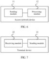
- FIG. 6 is a schematic structural diagram of Embodiment 1 of an access network device according to this application.
- the access network device includes a sending module 11 and a processing module 12.
- the sending module 11 is configured to send first control information to a first terminal device and send downlink data to the first terminal device, where the first control information is used to instruct the first terminal device to transmit the downlink data received from the access network device, to a second terminal device a plurality of times through a sidelink.
- the first control information includes a coordinated transmission instruction, first resource information, and second resource information; and the coordinated transmission instruction is used to instruct the first terminal device to transmit the downlink data received by the first terminal device based on the first resource information, to the second terminal device the plurality of times through the sidelink based on the second resource information.
- the processing module 12 is configured to form the second resource information based on a to-be-cancelled uplink scheduling resource.
- the sending module 11 is further configured to send second control information to a terminal device in a coverage area of the access network device, where the second control information carries an uplink scheduling cancellation instruction, and the uplink scheduling cancellation instruction is used to instruct the access network device to cancel the uplink scheduling resource of the terminal device.
- the processing module 12 may alternatively be configured to form the second resource information based on a new uplink resource allocated by the access network device for the second terminal device, and the new uplink resource is different from an uplink resource that has been scheduled by the access network device.
- the first control information is downlink control information DCI scrambled by the access network device by using a group identifier of a terminal device group or an identifier of the second terminal device; and the terminal device group includes the first terminal device and the second terminal device.
- the second control information is downlink control information DCI scrambled by the access network device by using a group identifier of a terminal device group or an identifier of the terminal device; and the terminal device group includes the first terminal device and the second terminal device.
- the second resource information includes first time-frequency resource configuration information and first transmission configuration information that are used when the first terminal device sends the downlink data to the second terminal device the plurality of times; and the first transmission configuration information includes at least one of a modulation and coding scheme MCS parameter, antenna configuration information, a quantity of transmissions, and version number-related information for a data retransmission that are used when the first terminal device sends the downlink data to the second terminal device.
- the first transmission configuration information includes at least one of a modulation and coding scheme MCS parameter, antenna configuration information, a quantity of transmissions, and version number-related information for a data retransmission that are used when the first terminal device sends the downlink data to the second terminal device.
- the first resource information includes second time-frequency resource configuration information and second transmission configuration information that are used when the first terminal device receives the downlink data; and the second transmission configuration information includes at least one of a modulation and coding scheme MCS parameter and antenna configuration information that are used when the first terminal device receives the downlink data.
- the access network device provided in this application may perform the foregoing method embodiment. Their implementation principles and technical effects are similar, and details are not described herein again.
- FIG. 7 is a schematic structural diagram of Embodiment 1 of a terminal device according to this application;
- the terminal device may be the first terminal device in the method embodiment.
- the first terminal device includes a receiving module 22 and a sending module 21.
- the receiving module 22 is configured to receive first control information sent by an access network device; and the sending module 21 is configured to transmit downlink data received by the receiving module 22 from the access network device, to a second terminal device a plurality of times through a sidelink based on the first control information.
- the first control information includes a coordinated transmission instruction, first resource information, and second resource information;
- the second resource information is information formed by the access network device based on a to-be-cancelled uplink scheduling resource.
- the second resource information is information formed by the access network device based on a new uplink resource allocated by the access network device for the second terminal device, and the new uplink resource is different from an uplink resource that has been scheduled by the access network device.
- the second resource information includes first time-frequency resource configuration information and first transmission configuration information that are used when the sending module 21 sends the downlink data to the second terminal device the plurality of times; and the first transmission configuration information includes at least one of a modulation and coding scheme MCS parameter, antenna configuration information, a quantity of transmissions, and version number-related information for a data retransmission that are used when the sending module 21 sends the downlink data to the second terminal device.
- the first transmission configuration information includes at least one of a modulation and coding scheme MCS parameter, antenna configuration information, a quantity of transmissions, and version number-related information for a data retransmission that are used when the sending module 21 sends the downlink data to the second terminal device.
- the first resource information includes second time-frequency resource configuration information and second transmission configuration information that are used when the receiving module 22 receives the downlink data; and the second transmission configuration information includes at least one of a modulation and coding scheme MCS related parameter and antenna configuration information that are used when the receiving module 22 receives the downlink data.
- the terminal device provided in this application may perform the foregoing method embodiment, and their implementation principles and technical effects are similar, and details are not described herein again.
- FIG. 8 is a schematic structural diagram of Embodiment 2 of an access network device according to this application.
- the access network device may include a transmitter 31, a processor 32, and a memory 33.
- the memory 33 may include a high-speed RAM memory, and may further include a non-volatile memory NVM, for example, at least one magnetic disk storage.
- the memory 33 may store various programs, to complete various processing functions and implement method steps in this embodiment.
- the transmitter 31 in this embodiment may be a radio frequency module or a baseband module on the access network device.
- the transmitter 31 is configured to send first control information to a first terminal device and send downlink data to the first terminal device, where the first control information is used to instruct the first terminal device to transmit the downlink data received from the access network device, to a second terminal device a plurality of times through a sidelink.
- the first control information includes a coordinated transmission instruction, first resource information, and second resource information; and the coordinated transmission instruction is used to instruct the first terminal device to transmit the downlink data received by the first terminal device based on the first resource information, to the second terminal device the plurality of times through the sidelink based on the second resource information.
- the processor 32 is configured to form the second resource information based on a to-be-cancelled uplink scheduling resource.
- the transmitter 31 is further configured to send second control information to a terminal device in a coverage area of the access network device, where the second control information carries an uplink scheduling cancellation instruction, and the uplink scheduling cancellation instruction is used to instruct the access network device to cancel the uplink scheduling resource of the terminal device.
- the processor 32 alternatively be configured to form the second resource information based on a new uplink resource allocated by the access network device for the second terminal device, and the new uplink resource is different from an uplink resource that has been scheduled by the access network device.
- the first control information is downlink control information DCI scrambled by the access network device by using a group identifier of a terminal device group or an identifier of the second terminal device; and the terminal device group includes the first terminal device and the second terminal device.
- the second control information is downlink control information DCI scrambled by the access network device by using a group identifier of a terminal device group or an identifier of the terminal device; and the terminal device group includes the first terminal device and the second terminal device.
- the second resource information includes first time-frequency resource configuration information and first transmission configuration information that are used when the first terminal device sends the downlink data to the second terminal device the plurality of times; and the first transmission configuration information includes at least one of a modulation and coding scheme MCS parameter, antenna configuration information, a quantity of transmissions, and version number-related information for a data retransmission that are used when the first terminal device sends the downlink data to the second terminal device.
- the first transmission configuration information includes at least one of a modulation and coding scheme MCS parameter, antenna configuration information, a quantity of transmissions, and version number-related information for a data retransmission that are used when the first terminal device sends the downlink data to the second terminal device.
- the first resource information includes second time-frequency resource configuration information and second transmission configuration information that are used when the first terminal device receives the downlink data; and the second transmission configuration information includes at least one of a modulation and coding scheme MCS parameter and antenna configuration information that are used when the first terminal device receives the downlink data.
- the access network device provided in this application may perform the foregoing method embodiment. Their implementation principles and technical effects are similar, and details are not described herein again.
- FIG. 9 is a schematic structural diagram of Embodiment 2 of a terminal device according to this application.
- the terminal device may be the first terminal device in the method embodiment.
- the terminal device may include a receiver 40, a transmitter 41, a processor 42, and a memory 43.
- the memory 43 may include a high-speed RAM memory, and may further include a non-volatile memory NVM, for example, at least one magnetic disk storage.
- the memory 43 may store various programs, to complete various processing functions and implement method steps in this embodiment.
- the receiver 40 and the transmitter 41 in this embodiment may be a radio frequency module or a baseband module on the terminal device.
- the receiver 40 and the transmitter 41 may be integrated to form a transceiver.
- the receiver 40 is configured to receive first control information sent by an access network device; and the transmitter 41 is configured to transmit downlink data received by the receiver 40 from the access network device, to a second terminal device through a sidelink a plurality of times based on the first control information.
- the first control information includes a coordinated transmission instruction, first resource information, and second resource information;
- the second resource information is information formed by the access network device based on a to-be-cancelled uplink scheduling resource.
- the second resource information is information formed by the access network device based on a new uplink resource allocated by the access network device for the second terminal device, and the new uplink resource is different from an uplink resource that has been scheduled by the access network device.
- the second resource information includes first time-frequency resource configuration information and first transmission configuration information that are used when the transmitter 41 sends the downlink data to the second terminal device the plurality of times; and the first transmission configuration information includes at least one of a modulation and coding scheme MCS parameter, antenna configuration information, a quantity of transmissions, and version number-related information for a data retransmission that are used when the transmitter 41 sends the downlink data to the second terminal device.
- the first transmission configuration information includes at least one of a modulation and coding scheme MCS parameter, antenna configuration information, a quantity of transmissions, and version number-related information for a data retransmission that are used when the transmitter 41 sends the downlink data to the second terminal device.
- the first resource information includes second time-frequency resource configuration information and second transmission configuration information that are used when the receiver 40 receives the downlink data; and the second transmission configuration information includes at least one of a modulation and coding scheme MCS related parameter and antenna configuration information that are used when the receiver 40 receives the downlink data.
- the terminal device provided in this application may perform the foregoing method embodiment, and their implementation principles and technical effects are similar, and details are not described herein again.
Landscapes
- Engineering & Computer Science (AREA)
- Signal Processing (AREA)
- Computer Networks & Wireless Communication (AREA)
- Quality & Reliability (AREA)
- Mobile Radio Communication Systems (AREA)
Claims (4)
- Datenübertragungsverfahren, umfassend:Senden (S201) von ersten Steuerinformationen durch eine Zugangsnetzwerkvorrichtung an ein erstes Endgerät, wobei die ersten Steuerinformationen verwendet werden, um das erste Endgerät anzuweisen, von der Zugangsnetzwerkvorrichtung empfangene Downlink-Daten eine Vielzahl von Male über einen Sidelink an ein zweites Endgerät zu übertragen; undSenden (S202) der Downlink-Daten durch die Zugangsnetzwerkvorrichtung an das erste Endgerät, wobei die ersten Steuerinformationen eine koordinierte Übertragungsanweisung, erste Ressourceninformationen und zweite Ressourceninformationen umfassen; unddie koordinierte Übertragungsanweisung verwendet wird, um das erste Endgerät anzuweisen, die von dem ersten Endgerät basierend auf den ersten Ressourceninformationen empfangenen Downlink-Daten basierend auf den zweiten Ressourceninformationen eine Vielzahl von Malen über den Sidelink an das zweite Endgerät zu übertragen, dadurch gekennzeichnet, dass das Datenübertragungsverfahren für eine ultrazuverlässige und latenzarme Kommunikation (URLLC) in einem 5G-Kommunikationssystem durchgeführt wird, wobei das Verfahren ferner Folgendes umfasstBilden der zweiten Ressourceninformation durch die Zugangsnetzwerkvorrichtung auf der Grundlage einer zu stornierenden Uplink-Planungsressource, oderBilden der zweiten Ressourceninformationen durch die Zugangsnetzwerkvorrichtung basierend auf einer neuen Uplink-Ressource, die von der Zugangsnetzwerkvorrichtung für das zweite Endgerät zugewiesen wurde, wobei sich die neue Uplink-Ressource von einer Uplink-Ressource unterscheidet, die von der Zugangsnetzwerkvorrichtung geplant wurde.
- Datenübertragungsverfahren nach Anspruch 1, ferner umfassend:Empfangen (S203) der von der Zugangsnetzwerkvorrichtung gesendeten ersten Steuerinformationen durch das erste Endgerät; undÜbertragen (S205) einer Vielzahl der von dem ersten Endgerät von der Zugangsnetzwerkvorrichtung empfangenen Downlink-Daten an das zweite Endgerät über den Sidelink auf der Grundlage der ersten Steuerinformationen, wobei das Übertragen der Vielzahl der von dem ersten Endgerät von der Zugangsnetzwerkvorrichtung empfangenen Downlink-Daten an das zweite Endgerät über den Sidelink auf der Grundlage der ersten Steuerinformationen insbesondere Folgendes umfasst:Empfangen (S204) der von der Zugangsnetzwerkvorrichtung gesendeten Downlink-Daten durch das erste Endgerät basierend auf den ersten Ressourceninformationen; undÜbertragen (S205) einer Vielzahl der Downlink-Daten durch das erste Endgerät an das zweite Endgerät über den Sidelink auf Grundlage der koordinierten Übertragungsanweisung und der zweiten Ressourceninformation.
- Zugangsnetzwerkvorrichtung, umfassend:ein Sendemodul (11), das dazu konfiguriert ist, erste Steuerinformationen an ein erstes Endgerät zu senden und Downlink-Daten an das erste Endgerät zu senden, wobeidie ersten Steuerinformationen verwendet werden, um das erste Endgerät anzuweisen, die von der Zugangsnetzwerkvorrichtung empfangenen Downlink-Daten eine Vielzahl von Malen über einen Sidelink an ein zweites Endgerät zu übertragen, wobei die ersten Steuerinformationen eine koordinierte Übertragungsanweisung, erste Ressourceninformationen und zweite Ressourceninformationen umfassen; unddie koordinierte Übertragungsanweisung verwendet wird, um das erste Endgerät anzuweisen, die von dem ersten Endgerät empfangenen Downlink-Daten basierend auf der ersten Ressourceninformation eine Vielzahl von Male über den Sidelink basierend auf der zweiten Ressourceninformation an das zweite Endgerät zu übertragen, dadurch gekennzeichnet, dass die Zugangsnetzwerkvorrichtung für eine ultrazuverlässige und latenzarme Kommunikation-, URLLC-, Übertragung in einem 5G-Kommunikationssystem konfiguriert ist, wobei die Zugangsnetzwerkvorrichtung ferner ein Verarbeitungsmodul (12) umfasst, unddas Verarbeitungsmodul (12) so konfiguriert ist, dass es die zweite Ressourceninformation auf der Grundlage einer zu stornierenden Uplink-Planungsressource bildet, oderdas Verarbeitungsmodul (12) dazu konfiguriert ist, die zweiten Ressourceninformationen auf der Grundlage einer neuen Uplink-Ressource zu erstellen, die von der Zugangsnetzwerkvorrichtung für das zweite Endgerät zugewiesen wurde, wobei sich die neue Uplink-Ressource von einer Uplink-Ressource unterscheidet, die von der Zugangsnetzwerkvorrichtung geplant wurde.
- System, umfassend die Zugangsknotenvorrichtung nach Anspruch 3 und ein Endgerät, wobei das Endgerät das erste Endgerät ist und das Endgerät Folgendes umfasst:ein Empfangsmodul (22), das zum Empfangen der von der Zugangsnetzwerkvorrichtung gesendeten ersten Steuerinformationen konfiguriert ist; undein Sendemodul (21), das dazu konfiguriert ist, die von dem Empfangsmodul von der Zugangsnetzwerkvorrichtung empfangenen Downlink-Daten basierend auf den ersten Steuerinformationen eine Vielzahl von Male über den Sidelink an das zweite Endgerät zu übertragen, wobeidas Empfangsmodul (22) ferner so konfiguriert ist, dass es basierend auf den ersten Ressourceninformationen die von der Zugangsnetzwerkvorrichtung gesendeten Downlink-Daten empfängt; unddas Sendemodul (21) speziell dazu konfiguriert ist, auf Grundlage der koordinierten Übertragungsanweisung und den zweiten Ressourceninformationen die Downlink-Daten eine Vielzahl von Malen über den Sidelink an das zweite Endgerät zu übertragen.
Applications Claiming Priority (2)
| Application Number | Priority Date | Filing Date | Title |
|---|---|---|---|
| CN201710522431.8A CN109217989B (zh) | 2017-06-30 | 2017-06-30 | 数据传输的方法、接入网设备和终端设备 |
| PCT/CN2018/092800 WO2019001409A1 (zh) | 2017-06-30 | 2018-06-26 | 数据传输的方法、接入网设备和终端设备 |
Publications (3)
| Publication Number | Publication Date |
|---|---|
| EP3629652A1 EP3629652A1 (de) | 2020-04-01 |
| EP3629652A4 EP3629652A4 (de) | 2020-05-13 |
| EP3629652B1 true EP3629652B1 (de) | 2024-09-18 |
Family
ID=64740416
Family Applications (1)
| Application Number | Title | Priority Date | Filing Date |
|---|---|---|---|
| EP18822695.5A Active EP3629652B1 (de) | 2017-06-30 | 2018-06-26 | Datenübertragungsverfahren, zugangsnetzwerkvorrichtung und endgerät |
Country Status (4)
| Country | Link |
|---|---|
| US (1) | US20200137782A1 (de) |
| EP (1) | EP3629652B1 (de) |
| CN (1) | CN109217989B (de) |
| WO (1) | WO2019001409A1 (de) |
Families Citing this family (21)
| Publication number | Priority date | Publication date | Assignee | Title |
|---|---|---|---|---|
| CN109257810B (zh) * | 2017-07-12 | 2022-05-10 | 华为技术有限公司 | 一种功率控制方法和终端设备 |
| AU2018430771B2 (en) * | 2018-07-05 | 2024-08-08 | Guangdong Oppo Mobile Telecommunications Corp., Ltd. | Method for transmitting data in internet of vehicles, and terminal device |
| KR102869906B1 (ko) | 2018-07-05 | 2025-10-14 | 광동 오포 모바일 텔레커뮤니케이션즈 코포레이션 리미티드 | 차량 인터넷에서의 데이터 전송 방법, 단말기 디바이스, 칩, 저장 매체, 컴퓨터 프로그램 제품 및 컴퓨터 프로그램 |
| CN111866791A (zh) * | 2019-04-28 | 2020-10-30 | 大唐移动通信设备有限公司 | 一种直通链路传输方法和终端 |
| CN111866814A (zh) * | 2019-04-30 | 2020-10-30 | 华为技术有限公司 | 通信方法和装置 |
| WO2020226399A1 (ko) * | 2019-05-03 | 2020-11-12 | 엘지전자 주식회사 | Nr v2x에서 전송 자원을 선택하는 방법 및 장치 |
| US11432291B2 (en) * | 2019-06-21 | 2022-08-30 | Huawei Technologies Co., Ltd. | System and scheme on group based identity and scrambling for UE cooperation transmission |
| WO2021007685A1 (zh) * | 2019-07-12 | 2021-01-21 | Oppo广东移动通信有限公司 | 用于传输侧行数据的方法、终端设备和网络设备 |
| CN112311493B (zh) * | 2019-07-23 | 2023-04-04 | 华为技术有限公司 | 协作传输方法、装置及设备 |
| EP3972171A4 (de) | 2019-08-08 | 2022-06-08 | Guangdong Oppo Mobile Telecommunications Corp., Ltd. | Datenübertragungsverfahren, endgerät und speichermedium |
| CN112449436B (zh) * | 2019-09-02 | 2024-07-09 | 华为技术有限公司 | 一种通信方法及装置 |
| CN114747281B (zh) | 2019-09-30 | 2024-12-31 | 中兴通讯股份有限公司 | 时频块取消 |
| WO2021066596A1 (ko) | 2019-10-04 | 2021-04-08 | 엘지전자 주식회사 | 상향링크 취소 지시를 모니터링하는 방법, 사용자기기, 장치, 및 컴퓨터 판독 가능 저장 매체, 그리고 상향링크 취소 지시를 전송하는 방법 및 기지국 |
| CN112714441B (zh) | 2019-10-24 | 2024-06-14 | 华为技术有限公司 | 一种数据传输方法、通信装置及通信系统 |
| WO2021097767A1 (zh) * | 2019-11-21 | 2021-05-27 | 华为技术有限公司 | 一种数据传输的方法、装置和系统 |
| US11818737B2 (en) * | 2019-12-18 | 2023-11-14 | Qualcomm Incorporated | Methods and apparatuses for data retransmission using sidelink diversity |
| WO2021128222A1 (zh) * | 2019-12-26 | 2021-07-01 | 华为技术有限公司 | 一种通信方法及装置 |
| EP4072213A4 (de) | 2019-12-30 | 2022-12-07 | Huawei Technologies Co., Ltd. | Kommunikationsverfahren und kommunikationsvorrichtung |
| US12349130B2 (en) | 2020-02-05 | 2025-07-01 | Beijing Xiaomi Mobile Software Co., Ltd. | Coverage enhancement method |
| WO2022222105A1 (zh) * | 2021-04-22 | 2022-10-27 | Oppo广东移动通信有限公司 | 无线通信方法及设备 |
| WO2025203553A1 (ja) * | 2024-03-29 | 2025-10-02 | Ntt株式会社 | 無線通信システム及び無線通信方法 |
Family Cites Families (9)
| Publication number | Priority date | Publication date | Assignee | Title |
|---|---|---|---|---|
| CN105451211B (zh) * | 2014-09-25 | 2019-12-27 | 中兴通讯股份有限公司 | 用于设备到设备通信的方法及装置 |
| CN106664700A (zh) * | 2014-09-25 | 2017-05-10 | 夏普株式会社 | 对于副链路通信中的模式切换的延迟减少 |
| WO2016095119A1 (zh) * | 2014-12-17 | 2016-06-23 | 华为技术有限公司 | 用户设备、基站及d2d通信的方法 |
| US9668194B2 (en) * | 2015-01-30 | 2017-05-30 | Huawei Technologies Co., Ltd. | System and method for coordinating device-to-device communications |
| CN106454687B (zh) * | 2015-07-21 | 2021-08-03 | 大唐移动通信设备有限公司 | 一种分配资源的方法和设备 |
| DE112015006791B4 (de) * | 2015-08-12 | 2024-02-22 | Apple Inc. | Verfahren zur Ermöglichung eines Relaisvorgangs mit hoher Datenrate unter Verwendung einer D2D-Luftschnittstelle |
| KR20170022224A (ko) * | 2015-08-19 | 2017-03-02 | 한국전자통신연구원 | 기회적 데이터 전송 방법 및 장치 |
| CN107852696A (zh) * | 2015-09-25 | 2018-03-27 | 富士通株式会社 | 边链路信息传输装置、方法以及通信系统 |
| CN106792890B (zh) * | 2016-07-29 | 2019-07-02 | 北京展讯高科通信技术有限公司 | D2d直接发现资源的选择方法及系统 |
-
2017
- 2017-06-30 CN CN201710522431.8A patent/CN109217989B/zh active Active
-
2018
- 2018-06-26 WO PCT/CN2018/092800 patent/WO2019001409A1/zh not_active Ceased
- 2018-06-26 EP EP18822695.5A patent/EP3629652B1/de active Active
-
2019
- 2019-12-23 US US16/725,889 patent/US20200137782A1/en not_active Abandoned
Also Published As
| Publication number | Publication date |
|---|---|
| CN109217989B (zh) | 2022-02-18 |
| EP3629652A4 (de) | 2020-05-13 |
| US20200137782A1 (en) | 2020-04-30 |
| EP3629652A1 (de) | 2020-04-01 |
| CN109217989A (zh) | 2019-01-15 |
| WO2019001409A1 (zh) | 2019-01-03 |
Similar Documents
| Publication | Publication Date | Title |
|---|---|---|
| EP3629652B1 (de) | Datenübertragungsverfahren, zugangsnetzwerkvorrichtung und endgerät | |
| EP2654235B1 (de) | HARQ zum dynamischen Ändern der TTD-UL/DL-Konfiguration in LTE-TDD-Systemen | |
| EP3975647B1 (de) | Drahtloskommunikationsverfahren, empfangsseitige vorrichtung und sendeseitige vorrichtung | |
| CN102201859B (zh) | 一种数据传输的方法及装置 | |
| US20210185658A1 (en) | Method, mobile station, and network apparatus for transmitting service | |
| EP3557776B1 (de) | Datenübertragungsverfahren, kommunikationsvorrichtung und datenübertragungssystem | |
| CN110267339B (zh) | 一种功率配置方法、用户设备及基站 | |
| CN108512576A (zh) | 一种实现用户设备协作的方法及装置 | |
| EP4593312A2 (de) | Sendeverfahren für sendezeitinformationen, empfangsverfahren für sendezeitinformationen und vorrichtung | |
| CN102804907A (zh) | 用于类型2中继的下行链路传输 | |
| WO2018233470A1 (zh) | 一种数据传输方法、通信设备和数据传输系统 | |
| CN103096494B (zh) | 基于跨载波调度的数据传输方法、用户设备和基站 | |
| CN113412595B (zh) | 无线通信方法、终端设备和网络设备 | |
| EP4138322A1 (de) | Kommunikationsverfahren und -vorrichtung | |
| CN102231662A (zh) | 一种数据传输的方法及装置 | |
| CN106301444A (zh) | 射频处理设备及处理方法 | |
| US20170135101A1 (en) | Method and Apparatus for Determining Data Transmission | |
| CN107210840B (zh) | 一种通信方法及通信设备 | |
| CN106538007B (zh) | 一种控制信息的传输方法、基站和用户设备 | |
| CN108702258B (zh) | 一种harq应答信息传输方法及设备 | |
| CN108702649B (zh) | 状态指示的传输装置、方法以及通信系统 | |
| CN115412888A (zh) | 发送、接收数据的方法、资源指示方法、装置及系统 | |
| CN113039851B (zh) | 无线通信方法、网络设备和终端设备 | |
| CN116114197B (zh) | 无线通信的方法、终端设备和网络设备 | |
| CN115118404A (zh) | Harq-ack的反馈方法及相关产品 |
Legal Events
| Date | Code | Title | Description |
|---|---|---|---|
| STAA | Information on the status of an ep patent application or granted ep patent |
Free format text: STATUS: THE INTERNATIONAL PUBLICATION HAS BEEN MADE |
|
| PUAI | Public reference made under article 153(3) epc to a published international application that has entered the european phase |
Free format text: ORIGINAL CODE: 0009012 |
|
| STAA | Information on the status of an ep patent application or granted ep patent |
Free format text: STATUS: REQUEST FOR EXAMINATION WAS MADE |
|
| 17P | Request for examination filed |
Effective date: 20191221 |
|
| AK | Designated contracting states |
Kind code of ref document: A1 Designated state(s): AL AT BE BG CH CY CZ DE DK EE ES FI FR GB GR HR HU IE IS IT LI LT LU LV MC MK MT NL NO PL PT RO RS SE SI SK SM TR |
|
| AX | Request for extension of the european patent |
Extension state: BA ME |
|
| A4 | Supplementary search report drawn up and despatched |
Effective date: 20200414 |
|
| RIC1 | Information provided on ipc code assigned before grant |
Ipc: H04L 1/18 20060101ALI20200406BHEP Ipc: H04W 72/04 20090101AFI20200406BHEP Ipc: H04W 88/04 20090101ALI20200406BHEP |
|
| DAV | Request for validation of the european patent (deleted) | ||
| DAX | Request for extension of the european patent (deleted) | ||
| STAA | Information on the status of an ep patent application or granted ep patent |
Free format text: STATUS: EXAMINATION IS IN PROGRESS |
|
| 17Q | First examination report despatched |
Effective date: 20210528 |
|
| REG | Reference to a national code |
Ref country code: DE Ref legal event code: R079 Free format text: PREVIOUS MAIN CLASS: H04W0072040000 Ipc: H04W0088040000 Ref country code: DE Ref legal event code: R079 Ref document number: 602018074557 Country of ref document: DE Free format text: PREVIOUS MAIN CLASS: H04W0072040000 Ipc: H04W0088040000 |
|
| GRAP | Despatch of communication of intention to grant a patent |
Free format text: ORIGINAL CODE: EPIDOSNIGR1 |
|
| STAA | Information on the status of an ep patent application or granted ep patent |
Free format text: STATUS: GRANT OF PATENT IS INTENDED |
|
| RIC1 | Information provided on ipc code assigned before grant |
Ipc: H04W 72/04 20090101ALI20240410BHEP Ipc: H04L 5/00 20060101ALI20240410BHEP Ipc: H04L 1/18 20060101ALI20240410BHEP Ipc: H04W 88/04 20090101AFI20240410BHEP |
|
| INTG | Intention to grant announced |
Effective date: 20240425 |
|
| GRAS | Grant fee paid |
Free format text: ORIGINAL CODE: EPIDOSNIGR3 |
|
| GRAA | (expected) grant |
Free format text: ORIGINAL CODE: 0009210 |
|
| STAA | Information on the status of an ep patent application or granted ep patent |
Free format text: STATUS: THE PATENT HAS BEEN GRANTED |
|
| AK | Designated contracting states |
Kind code of ref document: B1 Designated state(s): AL AT BE BG CH CY CZ DE DK EE ES FI FR GB GR HR HU IE IS IT LI LT LU LV MC MK MT NL NO PL PT RO RS SE SI SK SM TR |
|
| REG | Reference to a national code |
Ref country code: GB Ref legal event code: FG4D |
|
| REG | Reference to a national code |
Ref country code: CH Ref legal event code: EP |
|
| REG | Reference to a national code |
Ref country code: DE Ref legal event code: R096 Ref document number: 602018074557 Country of ref document: DE |
|
| REG | Reference to a national code |
Ref country code: IE Ref legal event code: FG4D |
|
| REG | Reference to a national code |
Ref country code: LT Ref legal event code: MG9D |
|
| PG25 | Lapsed in a contracting state [announced via postgrant information from national office to epo] |
Ref country code: NO Free format text: LAPSE BECAUSE OF FAILURE TO SUBMIT A TRANSLATION OF THE DESCRIPTION OR TO PAY THE FEE WITHIN THE PRESCRIBED TIME-LIMIT Effective date: 20241218 |
|
| PG25 | Lapsed in a contracting state [announced via postgrant information from national office to epo] |
Ref country code: GR Free format text: LAPSE BECAUSE OF FAILURE TO SUBMIT A TRANSLATION OF THE DESCRIPTION OR TO PAY THE FEE WITHIN THE PRESCRIBED TIME-LIMIT Effective date: 20241219 Ref country code: FI Free format text: LAPSE BECAUSE OF FAILURE TO SUBMIT A TRANSLATION OF THE DESCRIPTION OR TO PAY THE FEE WITHIN THE PRESCRIBED TIME-LIMIT Effective date: 20240918 |
|
| PG25 | Lapsed in a contracting state [announced via postgrant information from national office to epo] |
Ref country code: BG Free format text: LAPSE BECAUSE OF FAILURE TO SUBMIT A TRANSLATION OF THE DESCRIPTION OR TO PAY THE FEE WITHIN THE PRESCRIBED TIME-LIMIT Effective date: 20240918 |
|
| PG25 | Lapsed in a contracting state [announced via postgrant information from national office to epo] |
Ref country code: LV Free format text: LAPSE BECAUSE OF FAILURE TO SUBMIT A TRANSLATION OF THE DESCRIPTION OR TO PAY THE FEE WITHIN THE PRESCRIBED TIME-LIMIT Effective date: 20240918 |
|
| PG25 | Lapsed in a contracting state [announced via postgrant information from national office to epo] |
Ref country code: HR Free format text: LAPSE BECAUSE OF FAILURE TO SUBMIT A TRANSLATION OF THE DESCRIPTION OR TO PAY THE FEE WITHIN THE PRESCRIBED TIME-LIMIT Effective date: 20240918 |
|
| REG | Reference to a national code |
Ref country code: NL Ref legal event code: MP Effective date: 20240918 |
|
| PG25 | Lapsed in a contracting state [announced via postgrant information from national office to epo] |
Ref country code: RS Free format text: LAPSE BECAUSE OF FAILURE TO SUBMIT A TRANSLATION OF THE DESCRIPTION OR TO PAY THE FEE WITHIN THE PRESCRIBED TIME-LIMIT Effective date: 20241218 |
|
| PG25 | Lapsed in a contracting state [announced via postgrant information from national office to epo] |
Ref country code: RS Free format text: LAPSE BECAUSE OF FAILURE TO SUBMIT A TRANSLATION OF THE DESCRIPTION OR TO PAY THE FEE WITHIN THE PRESCRIBED TIME-LIMIT Effective date: 20241218 Ref country code: NO Free format text: LAPSE BECAUSE OF FAILURE TO SUBMIT A TRANSLATION OF THE DESCRIPTION OR TO PAY THE FEE WITHIN THE PRESCRIBED TIME-LIMIT Effective date: 20241218 Ref country code: LV Free format text: LAPSE BECAUSE OF FAILURE TO SUBMIT A TRANSLATION OF THE DESCRIPTION OR TO PAY THE FEE WITHIN THE PRESCRIBED TIME-LIMIT Effective date: 20240918 Ref country code: HR Free format text: LAPSE BECAUSE OF FAILURE TO SUBMIT A TRANSLATION OF THE DESCRIPTION OR TO PAY THE FEE WITHIN THE PRESCRIBED TIME-LIMIT Effective date: 20240918 Ref country code: GR Free format text: LAPSE BECAUSE OF FAILURE TO SUBMIT A TRANSLATION OF THE DESCRIPTION OR TO PAY THE FEE WITHIN THE PRESCRIBED TIME-LIMIT Effective date: 20241219 Ref country code: FI Free format text: LAPSE BECAUSE OF FAILURE TO SUBMIT A TRANSLATION OF THE DESCRIPTION OR TO PAY THE FEE WITHIN THE PRESCRIBED TIME-LIMIT Effective date: 20240918 Ref country code: BG Free format text: LAPSE BECAUSE OF FAILURE TO SUBMIT A TRANSLATION OF THE DESCRIPTION OR TO PAY THE FEE WITHIN THE PRESCRIBED TIME-LIMIT Effective date: 20240918 |
|
| REG | Reference to a national code |
Ref country code: AT Ref legal event code: MK05 Ref document number: 1725802 Country of ref document: AT Kind code of ref document: T Effective date: 20240918 |
|
| PG25 | Lapsed in a contracting state [announced via postgrant information from national office to epo] |
Ref country code: NL Free format text: LAPSE BECAUSE OF FAILURE TO SUBMIT A TRANSLATION OF THE DESCRIPTION OR TO PAY THE FEE WITHIN THE PRESCRIBED TIME-LIMIT Effective date: 20240918 |
|
| PG25 | Lapsed in a contracting state [announced via postgrant information from national office to epo] |
Ref country code: PT Free format text: LAPSE BECAUSE OF FAILURE TO SUBMIT A TRANSLATION OF THE DESCRIPTION OR TO PAY THE FEE WITHIN THE PRESCRIBED TIME-LIMIT Effective date: 20250120 Ref country code: IS Free format text: LAPSE BECAUSE OF FAILURE TO SUBMIT A TRANSLATION OF THE DESCRIPTION OR TO PAY THE FEE WITHIN THE PRESCRIBED TIME-LIMIT Effective date: 20250118 |
|
| PG25 | Lapsed in a contracting state [announced via postgrant information from national office to epo] |
Ref country code: SM Free format text: LAPSE BECAUSE OF FAILURE TO SUBMIT A TRANSLATION OF THE DESCRIPTION OR TO PAY THE FEE WITHIN THE PRESCRIBED TIME-LIMIT Effective date: 20240918 Ref country code: RO Free format text: LAPSE BECAUSE OF FAILURE TO SUBMIT A TRANSLATION OF THE DESCRIPTION OR TO PAY THE FEE WITHIN THE PRESCRIBED TIME-LIMIT Effective date: 20240918 |
|
| PG25 | Lapsed in a contracting state [announced via postgrant information from national office to epo] |
Ref country code: ES Free format text: LAPSE BECAUSE OF FAILURE TO SUBMIT A TRANSLATION OF THE DESCRIPTION OR TO PAY THE FEE WITHIN THE PRESCRIBED TIME-LIMIT Effective date: 20240918 |
|
| PG25 | Lapsed in a contracting state [announced via postgrant information from national office to epo] |
Ref country code: AT Free format text: LAPSE BECAUSE OF FAILURE TO SUBMIT A TRANSLATION OF THE DESCRIPTION OR TO PAY THE FEE WITHIN THE PRESCRIBED TIME-LIMIT Effective date: 20240918 Ref country code: EE Free format text: LAPSE BECAUSE OF FAILURE TO SUBMIT A TRANSLATION OF THE DESCRIPTION OR TO PAY THE FEE WITHIN THE PRESCRIBED TIME-LIMIT Effective date: 20240918 |
|
| PG25 | Lapsed in a contracting state [announced via postgrant information from national office to epo] |
Ref country code: CZ Free format text: LAPSE BECAUSE OF FAILURE TO SUBMIT A TRANSLATION OF THE DESCRIPTION OR TO PAY THE FEE WITHIN THE PRESCRIBED TIME-LIMIT Effective date: 20240918 Ref country code: PL Free format text: LAPSE BECAUSE OF FAILURE TO SUBMIT A TRANSLATION OF THE DESCRIPTION OR TO PAY THE FEE WITHIN THE PRESCRIBED TIME-LIMIT Effective date: 20240918 |
|
| PG25 | Lapsed in a contracting state [announced via postgrant information from national office to epo] |
Ref country code: SK Free format text: LAPSE BECAUSE OF FAILURE TO SUBMIT A TRANSLATION OF THE DESCRIPTION OR TO PAY THE FEE WITHIN THE PRESCRIBED TIME-LIMIT Effective date: 20240918 Ref country code: IT Free format text: LAPSE BECAUSE OF FAILURE TO SUBMIT A TRANSLATION OF THE DESCRIPTION OR TO PAY THE FEE WITHIN THE PRESCRIBED TIME-LIMIT Effective date: 20240918 |
|
| REG | Reference to a national code |
Ref country code: DE Ref legal event code: R097 Ref document number: 602018074557 Country of ref document: DE |
|
| PGFP | Annual fee paid to national office [announced via postgrant information from national office to epo] |
Ref country code: DE Payment date: 20250429 Year of fee payment: 8 |
|
| PG25 | Lapsed in a contracting state [announced via postgrant information from national office to epo] |
Ref country code: DK Free format text: LAPSE BECAUSE OF FAILURE TO SUBMIT A TRANSLATION OF THE DESCRIPTION OR TO PAY THE FEE WITHIN THE PRESCRIBED TIME-LIMIT Effective date: 20240918 |
|
| PGFP | Annual fee paid to national office [announced via postgrant information from national office to epo] |
Ref country code: GB Payment date: 20250508 Year of fee payment: 8 |
|
| PLBE | No opposition filed within time limit |
Free format text: ORIGINAL CODE: 0009261 |
|
| STAA | Information on the status of an ep patent application or granted ep patent |
Free format text: STATUS: NO OPPOSITION FILED WITHIN TIME LIMIT |
|
| 26N | No opposition filed |
Effective date: 20250619 |
|
| PG25 | Lapsed in a contracting state [announced via postgrant information from national office to epo] |
Ref country code: SE Free format text: LAPSE BECAUSE OF FAILURE TO SUBMIT A TRANSLATION OF THE DESCRIPTION OR TO PAY THE FEE WITHIN THE PRESCRIBED TIME-LIMIT Effective date: 20240918 |
|
| REG | Reference to a national code |
Ref country code: CH Ref legal event code: H13 Free format text: ST27 STATUS EVENT CODE: U-0-0-H10-H13 (AS PROVIDED BY THE NATIONAL OFFICE) Effective date: 20260127 |
|
| PG25 | Lapsed in a contracting state [announced via postgrant information from national office to epo] |
Ref country code: MC Free format text: LAPSE BECAUSE OF FAILURE TO SUBMIT A TRANSLATION OF THE DESCRIPTION OR TO PAY THE FEE WITHIN THE PRESCRIBED TIME-LIMIT Effective date: 20240918 |
|
| PG25 | Lapsed in a contracting state [announced via postgrant information from national office to epo] |
Ref country code: LU Free format text: LAPSE BECAUSE OF NON-PAYMENT OF DUE FEES Effective date: 20250626 |
|
| REG | Reference to a national code |
Ref country code: BE Ref legal event code: MM Effective date: 20250630 |