EP3629983B1 - Systèmes chirurgicaux robotiques et drapés pour recouvrir des composants de systèmes chirurgicaux robotiques - Google Patents
Systèmes chirurgicaux robotiques et drapés pour recouvrir des composants de systèmes chirurgicaux robotiques Download PDFInfo
- Publication number
- EP3629983B1 EP3629983B1 EP18805856.4A EP18805856A EP3629983B1 EP 3629983 B1 EP3629983 B1 EP 3629983B1 EP 18805856 A EP18805856 A EP 18805856A EP 3629983 B1 EP3629983 B1 EP 3629983B1
- Authority
- EP
- European Patent Office
- Prior art keywords
- drape
- end portion
- inlet
- robotic
- surgical
- Prior art date
- Legal status (The legal status is an assumption and is not a legal conclusion. Google has not performed a legal analysis and makes no representation as to the accuracy of the status listed.)
- Active
Links
Images


Classifications
-
- A—HUMAN NECESSITIES
- A61—MEDICAL OR VETERINARY SCIENCE; HYGIENE
- A61B—DIAGNOSIS; SURGERY; IDENTIFICATION
- A61B46/00—Surgical drapes
- A61B46/10—Surgical drapes specially adapted for instruments, e.g. microscopes
-
- A—HUMAN NECESSITIES
- A61—MEDICAL OR VETERINARY SCIENCE; HYGIENE
- A61B—DIAGNOSIS; SURGERY; IDENTIFICATION
- A61B34/00—Computer-aided surgery; Manipulators or robots specially adapted for use in surgery
- A61B34/30—Surgical robots
-
- A—HUMAN NECESSITIES
- A61—MEDICAL OR VETERINARY SCIENCE; HYGIENE
- A61B—DIAGNOSIS; SURGERY; IDENTIFICATION
- A61B34/00—Computer-aided surgery; Manipulators or robots specially adapted for use in surgery
- A61B34/30—Surgical robots
- A61B34/35—Surgical robots for telesurgery
-
- A—HUMAN NECESSITIES
- A61—MEDICAL OR VETERINARY SCIENCE; HYGIENE
- A61B—DIAGNOSIS; SURGERY; IDENTIFICATION
- A61B34/00—Computer-aided surgery; Manipulators or robots specially adapted for use in surgery
- A61B34/30—Surgical robots
- A61B34/37—Leader-follower robots
-
- A—HUMAN NECESSITIES
- A61—MEDICAL OR VETERINARY SCIENCE; HYGIENE
- A61B—DIAGNOSIS; SURGERY; IDENTIFICATION
- A61B50/00—Containers, covers, furniture or holders specially adapted for surgical or diagnostic appliances or instruments, e.g. sterile covers
- A61B50/10—Furniture specially adapted for surgical or diagnostic appliances or instruments
- A61B50/13—Trolleys, e.g. carts
-
- B—PERFORMING OPERATIONS; TRANSPORTING
- B25—HAND TOOLS; PORTABLE POWER-DRIVEN TOOLS; MANIPULATORS
- B25J—MANIPULATORS; CHAMBERS PROVIDED WITH MANIPULATION DEVICES
- B25J19/00—Accessories fitted to manipulators, e.g. for monitoring, for viewing; Safety devices combined with or specially adapted for use in connection with manipulators
- B25J19/0054—Cooling means
-
- A—HUMAN NECESSITIES
- A61—MEDICAL OR VETERINARY SCIENCE; HYGIENE
- A61B—DIAGNOSIS; SURGERY; IDENTIFICATION
- A61B17/00—Surgical instruments, devices or methods
- A61B2017/00477—Coupling
-
- A—HUMAN NECESSITIES
- A61—MEDICAL OR VETERINARY SCIENCE; HYGIENE
- A61B—DIAGNOSIS; SURGERY; IDENTIFICATION
- A61B34/00—Computer-aided surgery; Manipulators or robots specially adapted for use in surgery
- A61B34/30—Surgical robots
- A61B2034/302—Surgical robots specifically adapted for manipulations within body cavities, e.g. within abdominal or thoracic cavities
-
- A—HUMAN NECESSITIES
- A61—MEDICAL OR VETERINARY SCIENCE; HYGIENE
- A61B—DIAGNOSIS; SURGERY; IDENTIFICATION
- A61B90/00—Instruments, implements or accessories specially adapted for surgery or diagnosis and not covered by any of the groups A61B1/00 - A61B50/00, e.g. for luxation treatment or for protecting wound edges
- A61B90/06—Measuring instruments not otherwise provided for
- A61B2090/064—Measuring instruments not otherwise provided for for measuring force, pressure or mechanical tension
-
- A—HUMAN NECESSITIES
- A61—MEDICAL OR VETERINARY SCIENCE; HYGIENE
- A61B—DIAGNOSIS; SURGERY; IDENTIFICATION
- A61B34/00—Computer-aided surgery; Manipulators or robots specially adapted for use in surgery
- A61B34/70—Manipulators specially adapted for use in surgery
- A61B34/74—Manipulators with manual electric input means
-
- A—HUMAN NECESSITIES
- A61—MEDICAL OR VETERINARY SCIENCE; HYGIENE
- A61B—DIAGNOSIS; SURGERY; IDENTIFICATION
- A61B90/00—Instruments, implements or accessories specially adapted for surgery or diagnosis and not covered by any of the groups A61B1/00 - A61B50/00, e.g. for luxation treatment or for protecting wound edges
- A61B90/06—Measuring instruments not otherwise provided for
Definitions
- Robotic surgical systems have been used in minimally invasive medical procedures.
- Some robotic surgical systems include a console supporting a surgical robotic arm and a surgical instrument, having at least one end effector (e.g., forceps or a grasping tool), mounted to the robotic arm.
- the robotic arm provides mechanical power to the surgical instrument for its operation and movement.
- Manually-operated surgical instruments often included a handle assembly for actuating the functions of the surgical instrument.
- no handle assembly is typically present to actuate the functions of the end effector.
- an instrument drive unit is used to interface with the selected surgical instrument to drive operations of the surgical instrument.
- an instrument drive unit, robotic arm, robotic cart, and/or other components of the robotic surgical system generates heat.
- An excess of heat may damage or impair the functioning of various components of the instrument drive unit or other components of the robotic surgical system. Accordingly, it would be beneficial to provide a means for cooling the components of the surgical system while also maintaining the sterility of the surgical system.
- WO 2016/079532 A1 discloses a drape for a robotic arm configured to allow fluid flow through the drape, the drape defines one or both of an inward fluid path for leading cooling fluid to the robotic arm and a return fluid path for leading cooling fluid from the robotic arm.
- the drape according to the invention is defined in claim 1.
- the robotic surgical system according to the invention is defined in claim 5.
- Preferred embodiments are defined in the dependent claims.
- a drape for covering and facilitating cooling of a robotic surgical system includes a first end portion, a second end portion, and an intermediate portion extending between the first and second end portions.
- the first end portion has an outer surface and an inner surface and defines an inlet through the outer and inner surfaces.
- the first end portion also defines a cavity therein.
- the cavity is dimensioned for receipt of an instrument drive unit and is in fluid communication with the inlet.
- the second end portion has an outer surface and an inner surface and defines an outlet through the outer and inner surfaces.
- the second end portion further defines a cavity therein that is in fluid communication with the outlet.
- the intermediate portion defines an elongated conduit therethrough dimensioned for receipt of a surgical robotic arm.
- the inlet includes a first inlet and a second inlet.
- the inlet may be annular and dimensioned to surround a sterile interface module.
- the first end portion may include a patch that covers the second inlet and is configured to permit ingress of air through the inlet.
- the patch is fabricated from a liquid resistant, air-permeable material.
- the first end portion of the drape may include a first flap and a second flap each extending from the outer surface of the first end portion.
- the first flap may overlap with the inlet to define a first portion of a fluid pathway.
- the second flap may overlap with the first flap to define a second portion of the fluid pathway.
- the first and second portions of the fluid pathway may be parallel with one another and in fluid communication with one another.
- the first end portion may also include a first rib and a second rib.
- the first rib may be disposed in and extend parallel with the first portion of the fluid pathway to maintain a spacing between the first flap and the outer surface.
- the second rib may be disposed in and extend parallel with the second portion of the fluid pathway to maintain a spacing between the first and second flaps.
- the second end portion may define a vent through the outer and inner surfaces of the second portion.
- a robotic surgical system in another aspect of the present disclosure, includes a surgical robotic arm, a surgical assembly coupled to a first end portion of the surgical robotic arm, and a drape for covering the surgical robotic arm and the surgical assembly.
- the drape includes a first end portion, a second end portion, and an intermediate portion extending between the first and second end portions.
- the first end portion has an outer surface and an inner surface and defines an inlet through the outer and inner surfaces.
- the first end portion further defines a cavity therein.
- the cavity is dimensioned for receipt of the surgical assembly and is in fluid communication with the inlet.
- the second end portion has an outer surface and an inner surface and defines an outlet through the outer and inner surfaces.
- the second end portion further defines a cavity therein that is in fluid communication with the outlet.
- the intermediate portion defines an elongated conduit therethrough dimensioned for receipt of the surgical robotic arm.
- the surgical assembly may include a fan configured to draw air from a sterile field of a surgery, through the inlet of the drape, into the surgical assembly, out of the drape through the outlet thereof, and away from the sterile field of the surgery.
- the robotic surgical system may further include a controller in communication with the fan.
- the controller may be configured to adjust a speed of the fan based on an orientation of the robotic arm.
- the speed of the fan may be adjusted using measurements taken by strain gauges coupled at joints of the surgical robotic arm.
- the controller may also be configured to adjust a speed of the fan based on thermal sensors, current sensors, and/or tachometers and/or encoders within the fan.
- the robotic surgical system may further include a vent attached to the drape.
- the controller may be further configured to move the vent between open and closed configurations based on a temperature within the drape and/or a speed of a fan.
- the surgical assembly may include an instrument drive unit having a first end portion and a second end portion.
- a fan may be attached to the first end portion.
- the surgical assembly may include a sterile interface module coupled to the second end portion of the instrument drive unit.
- the sterile interface module may be configured to be surrounded by the inlet of the drape to permit air to pass into the cavity of the first end portion of the drape via the sterile interface module.
- the instrument drive unit may have a plurality of fluid channels extending from the first end portion of the instrument drive unit to the second end portion of the instrument drive unit. The fluid channels may take a tortuous pathway through the instrument drive unit such that ingress of liquids is prevented and ingress of air is allowed.
- the robotic surgical system may further include a robotic cart having a first end portion and a second end portion.
- the cavity of the second end portion of the drape may be dimensioned to receive at least one of the first or second end portions of the robotic cart.
- the robotic cart may have a fan that directs air flow in a direction from the first end portion of the drape toward the second end portion of the drape through the conduit of the drape.
- the drape may include an elongated conductive rib extending along an inner surface of the intermediate portion of the drape.
- the inlet of the drape may be annular and dimensioned to surround a distal end portion of an instrument drive unit of the surgical assembly.
- the first end portion of the drape includes a patch covering the second inlet and configured to permit ingress of air through the inlet.
- the patch is fabricated from a liquid resistant, air-permeable material.
- the first end portion of the drape may include a first flap and a second flap each extending from the outer surface of the first end portion.
- the first flap may overlap with the inlet to define a first portion of a fluid pathway.
- the second flap may overlap with the first flap to define a second portion of the fluid pathway.
- the first and second portions of the fluid pathway may be parallel with one another and in fluid communication with one another.
- the first end portion may also include a first rib and a second rib.
- the first rib may be disposed in and extend parallel with the first portion of the fluid pathway to maintain a spacing between the first flap and the outer surface.
- the second rib may be disposed in and extend parallel with the second portion of the fluid pathway to maintain a spacing between the first and second flaps.
- the drape may further include a tubular member extending along the intermediate portion thereof.
- the tubular member may include a proximal opening disposed within the first end portion of the drape and a distal opening disposed adjacent the second end portion of the drape such that air travels into the tubular member from the first end portion of the drape via the proximal opening and exits the tubular member via the distal opening.
- parallel and perpendicular are understood to include relative configurations that are substantially parallel and substantially perpendicular up to about plus or minus 10 degrees from true parallel and true perpendicular.
- Embodiments of the presently disclosed robotic surgical system including a robotic arm cart, a surgical robotic arm, a surgical assembly (including an instrument drive unit (“IDU”) and a surgical instrument), and a drape for covering some or all of the aforementioned components, are described in detail with reference to the drawings, in which like reference numerals designate identical or corresponding elements in each of the several views.
- distal refers to that portion of the robotic arm cart, surgical robotic arm, surgical assembly, or drape, that is closer to the patient
- proximal refers to that portion of the robotic arm cart, surgical robotic arm, surgical assembly, or drape, that is farther from the patient.
- a drape for covering and facilitating cooling various components of a robotic surgical system.
- the drape maintains sterility of the surgical assembly disposed therein and cools the components thereof by facilitating the transfer of air through the drape and away from the surgical assembly.
- the surgical assembly includes a fan or fans, heat sinks, and a labyrinth of channels defined through the components of the surgical assembly to facilitate cooling thereof.
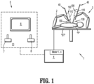
- a surgical system such as, for example, a robotic surgical system 1, generally includes a robotic arm or robotic arms 2, 3 coupled to a robotic cart 10, a surgical assembly 100 coupled to the surgical robotic arm 2, and a drape 200 ( FIGS. 4A-4C ) for covering the robotic arm 2 and the surgical assembly 100.
- the drape 200 may be dimensioned to also cover the robotic arm cart 10.
- the surgical assembly 100 includes an instrument drive unit (hereinafter "IDU") 110 coupled to a slide rail 40 of surgical robotic arms 2, 3, and an electromechanical surgical instrument 130 operably coupled to IDU 110 by a sterile interface module 112 of surgical assembly 100.
- IDU instrument drive unit
- the surgical system 1 further includes a control device 4 and an operating console 5 coupled with control device 4.
- Operating console 5 includes a display device 6, which is set up in particular to display three-dimensional images; and manual input devices 7, 8, by means of which a person (not shown), for example a surgeon, is able to telemanipulate robotic arms 2, 3 in a first operating mode, as known in principle to a person skilled in the art.
- Each of the robotic arms 2, 3 may be composed of a plurality of members 2a, 2b, 2c, which are connected through joints. Robotic arms 2, 3 may be driven by electric drives (not shown) that are connected to control device 4.
- Control device 4 e.g., a computer
- Control device 4 may be set up to activate the drives, in particular by means of a computer program, in such a way that robotic arms 2, 3, the attached robotic surgical assembly 100, and thus electromechanical surgical instrument 130 (including an electromechanical end effector (not shown)) execute a desired movement according to a movement defined by means of manual input devices 7, 8.
- Control device 4 may also be set up in such a way that it regulates the movement of robotic arms 2, 3.
- Robotic surgical system 1 is configured for use on a patient "P" lying on a surgical table “ST” to be treated in a minimally invasive manner by means of a surgical instrument, e.g., electromechanical surgical instrument 130.
- robotic arms 2, 3 may be coupled to robotic arm cart 10 ( FIG. 2 ) rather than surgical table "ST.”
- Robotic surgical system 1 may also include more than two robotic arms 2, 3, the additional robotic arms likewise being connected to control device 4 and being telemanipulatable by means of operating console 5.
- a surgical instrument for example, electromechanical surgical instrument 130 (including the electromechanical end effector), may also be attached to the additional robotic arm.
- Control device 4 may control a plurality of motors, e.g., motors (Motor 1 ...n), with each motor configured to drive movement of robotic arms 2, 3 in a plurality of directions. Further, control device 4 may control a motor assembly 114 ( FIG. 7 ) of IDU 110 of robotic surgical assembly 100 that drives various operations of surgical instrument 130. In addition, control device 4 may control the operation of a rotation motor, such as, for example, a canister motor "M" ( FIG. 13 ) of IDU 110 of surgical assembly 100, configured to drive a relative rotation of motor assembly 114 of IDU 110 and in turn electromechanical surgical instrument 130. In embodiments, each motor 114 of the IDU 110 can be configured to actuate a drive rod/cable or a lever arm to effect operation and/or movement of electromechanical surgical instrument 130.
- motors Motor 1 ...n
- drape 200 of robotic surgical system 1 has a generally elongated configuration, such as, for example, a tubular shape, and is fabricated from a resilient material, such as, for example, a natural and/or synthetic fabric or layered material that is impermeable to liquids/moisture.
- Drape 200 may in embodiments be a single layer or a laminate or fabric, and may be made, e.g., of a nonwoven spun bonded olefin fiber material known as TYVEK ® , which is vapor/gas permeable, liquid-resistive, and prevents liquids or contaminants from passing therethrough.
- drape 200 may be made of low-density polyethylene (LDPE), high-density polyethylene (HDPE), polypropylene, polyurethane, and/or polyethylene materials or other similar non-toxic, biocompatible compounds. In some embodiments, only some portions of drape 200 may be fabricated from liquid resistant, air-permeable material and at various locations of drape 200. Drape 200 may be translucent so that the components of surgical assembly 100 that drape 200 covers remain visible to a clinician. It is contemplated that drape 200 may be opaque rather than translucent or opaque and translucent along varying portions.
- Drape 200 has a first end portion or distal end portion 200a, a second end portion or proximal end portion 200b, and an intermediate portion 200c extending between the first and second end portions 200a, 200b.
- a high density polyethylene spun woven fiber or synthetic fabric may be glued, thermally bonded, ultrasonically welded, stitched, hook and loop fastened, or seam bonded onto drape 200.
- the drape 200 may have any suitable length to cover various portions of the surgical system 1.
- drape 200 may have a sufficient length to at least allow for second end portion 200b of drape 100 to fit over a base or proximal portion 42 of surgical robotic arm 2.
- drape 200 may have a sufficient length to at least allow for second end portion 200b to fit over a handle portion 12 of robotic arm cart 10 and be secured to a post 14 of robotic arm cart 10.
- drape 200 may have a sufficient length to at least allow for second end portion 200b thereof to fit over a base 16 of cart 10.
- Drape 200 may have a length to accommodate robotic arm 2 in a fully extended position.
- drape 200 of surgical system 1 is defined by a drape wall 206 having an outer surface 202 and an inner surface 204.
- Drape wall 206 may be fabricated from the same or a single material and be monolithically formed, or, in some embodiments, drape wall 206 may be fabricated from layers of different materials or from the same material having different properties.
- the inner surface 204 of drape 200 at the first end portion 200a thereof defines a cavity 208 therein. Cavity 208 of first end portion 200a is dimensioned to receive or encapsulate surgical assembly 100 (e.g., instrument drive unit 110 and slide rail 40).
- first end portion 200a of drape 200 defines an inlet or channel 210 extending through the outer surface 202 and the inner surface 204 of drape 200.
- Inlet 210 is in fluid communication with cavity 208 of first end portion 200a.
- inlet 210 provides ingress of air flow "F" into drape 200 to cool components of surgical assembly 100.
- Inlet 210 has a generally circular or annular shape dimensioned to form a fluid-tight seal with sterile interface module 112 of surgical assembly 100.
- inlet 210 may be dimensioned to form a fluid tight seal with a distal end portion 110b ( FIG. 3 ) of instrument drive unit 210 when sterile interface module 112 is not used.
- drape 200 is placed over rail 40 and instrument drive unit 110, and sterile interface module 112 is positioned to extend through inlet 210 of drape 200 with surgical instrument 130 protruding from outer surface 202 of drape 200.
- Inlet 210 of drape 200 includes a ring (not shown) configured to couple sterile interface module 112 thereto while allowing sterile interface module 112 to rotate relative to and within inlet 210 of drape 200.
- Air flow "F" travels through dedicated openings 180 defined in sterile interface module 112 and infiltrates first end portion 200a of drape 200.
- drape 200 may have two inlets at first end portion 200a, as will be described.
- intermediate portion 200c of drape 200 is dimensioned to encapsulate or house elongate members 2a, 2b, 2c of surgical robotic arm 2.
- intermediate portion 200c of drape 200 defines an elongated conduit 212 extending longitudinally therethrough and dimensioned for receipt of a surgical robotic arm, for example, robotic arm 2.
- Conduit 212 of intermediate portion 200c has a length dimensioned to accommodate robotic arm 2.
- the length of conduit 212 is dimensioned to accommodate at least an entire length of robotic arm 2 when robotic arm 2 has each of its elongate members 2a, 2b, 2c in an extended state.
- Intermediate portion 200c of drape 200 may be fabricated from the same materials as first end portion 200a thereof.
- intermediate portion 200c of drape 200 may be fabricated from a different material, or the same material having a different flexibility, as compared to first end portion 200a.
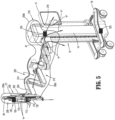
- Intermediate portion 200c of drape 200 may have an elongated conductive rib or fin 214 ( FIG. 5 ) attached to and extending from inner surface 204 of drape 200.
- Fin 214 may be constructed of a thermally-conductive material, such as, for example, woven metals, graphite, copper, or aluminum. Fin 214 may act as a heat sink to facilitate passing heat away from first end portion 200a of drape 200 towards second end portion 200b of drape 200.
- fin 214 may be a thermoelectric cooling module for applying active cooling to the air passing thereby. It is contemplated that thermoelectric cooling modules may be positioned at various locations throughout drape 200.
- Second end portion 200b of drape 200 defines a cavity 216 therein. Cavity 216 of second end portion 200b is dimensioned to receive or encapsulate at least proximal portion 42 of robotic arm 2 and/or a portion or portions of robotic arm cart 10. Second end portion 200b of drape 200 has an outlet or channel 218 extending through the drape wall 206 of drape 200. As such, outlet 218 of second end portion 200b of drape 200 is in fluid communication with cavity 216 of second end portion 200b of drape 200. Outlet 218 of drape 200 has a generally circular or annular shape that is dimensioned to fit over handle portion of cart 10 and/or cart 10, in embodiments over the entirety of handle portion of cart 10.
- Outlet 218 of second end portion 200b of drape 200 may be located at a proximal-most end of drape 200 rather than a side of drape 200 as is inlet 210 of first end portion 200a. As such, drape 200 is open at its proximal-most end, whereas drape 200 is closed at its distal-most end. It is contemplated that outlet 218 may be located anywhere along a length of drape 200.
- outlet 218 of drape 200 may include an adhesive lining (not shown) disposed/formed on an inner periphery thereof (e.g., on inner surface 204 of drape 200) for fixing second end portion 200b of drape 200 to cart 10.
- outlet 218 of drape 200 may include an elastic band (not explicitly shown), a hook and loop fastener, cinch line, bungee hooks, magnetic material, or the like, surrounding a periphery of second end portion 200b to assist in securing cart 10 within outlet 218 of second end portion 200b.
- outlet 218 may have a tie cord (not explicitly shown) disposed about the periphery of outlet 218 to allow for the diameter of outlet 218 to be adjusted to fit over and secure to various portions of cart 10.
- a tie cord (not explicitly shown) disposed about the periphery of outlet 218 to allow for the diameter of outlet 218 to be adjusted to fit over and secure to various portions of cart 10.
- second end portion 200b of drape 200 may include one or more pressure-sensitive vents 220 disposed in drape wall 206 of drape 200. Vents 220 are configured to open upon cavity 216 of second end portion 200b of drape 200 achieving a threshold amount of air pressure therein. In this way, if outlet 218 of drape 200 is closed or secured tightly against cart 10 or the like, causing air pressure to build up within second end portion 200b, vents 220 may passively open or may be configured to allow for a continuous passage of air from first end portion 200a, through intermediate portion 200c, and out of second end portion 200b of drape 200 via vents 220. In some embodiments, vents 220 may be in communication with control device 4 ( FIG.
- vents 220 which may be configured to move vents 220, via a servomechanism or hydraulic drive system for example, between open and closed states based on a temperature or pressure within first end portion 200a, intermediate portion 200c, and/or second end portion 200b of drape 200. It is contemplated that control device 4 may be configured to move vents 220 between the opened and closed states based on a speed of fan 150 of IDU 110. It is contemplated that vents 220 may be configured to remain open to act as inlets rather than outlets. Vents 220 may be fabricated from a liquid-resistant, air-permeable material (e.g., polyethylene fibers or polypropylene) which permits passive passage of air flow therethrough.
- a liquid-resistant, air-permeable material e.g., polyethylene fibers or polypropylene
- vents 220 may be coupled to drape wall 206 of drape 200 using a piece of shape memory material (e.g., a shape memory alloy) configured to expand upon achieving a threshold temperature. As such, the shape memory material lifts or raises vent 220 relative to drape wall 206, thereby creating an opening in drape wall 206 for air to pass through.
- shape memory material e.g., a shape memory alloy
- Second end portion 200b may also include a fan (not shown) that draws air from first end portion 200a toward outlet 218 of second end portion 200b of drape 200.
- cart 10 may include fans 222, 224 attached to base 16 and/or handle portion 12 of cart 10, respectively.
- Fans 222, 224 of cart 10 may draw air from first end portion 200a of drape 200 toward outlet 218 of second end portion 200b of drape 200.
- second end portion 200b of drape 200 is placed over handle portion 12 of cart 10 and secured to the post 14 of cart 10, as shown in FIG. 5 .
- second end portion 200b of drape 200 may cover handle portion 12, post 14, and base 16 of cart 10 and be secured to an under-surface of base 16 of cart 10 as shown in FIG. 6 . While second end portion 200b of drape 200 is secured to cart 10, outlet 218 of second end portion 200b of drape 200 remains open to allow for air flow "F" to pass through.
- the fan 150 of IDU 110 is activated to generate negative pressure within cavity 208 of first end portion 200a, which draws the air flow "F” into drape 200 through sterile interface module 112, from the sterile field. Air flow “F” continues to travel through the IDU 110 to cool components of the IDU 110. The air flow “F” then travels out of the IDU 110 through the fan 150 and through the first end portion 200a, the intermediate portion 200c, and then the second end portion 200b of drape 200. The air flow "F,” now warmed by absorbing heat generated from the operation of IDU 110, will ultimately move out of drape 200 via outlet 218 and/or vents 220 and into the operating room or non-sterile field.
- Drape 300 includes a drape wall 306 having an outer surface 302 and an inner surface 304.
- Outer surface 302 and inner surface 304 of drape wall 306 are each fabricated from the same material, and are monolithically formed with one another.
- one or each of the outer surface 302 and the inner surface 304 of drape wall 306 of drape 300 may be fabricated from different layers of materials or the same material having different properties.
- the inner surface 304 at a first end portion 300a of drape 300 defines a cavity 308 therein. Cavity 308 of first end portion 300a of drape 300 is dimensioned to receive or encapsulate surgical assembly 100 (e.g., instrument drive unit 110 and slide rail 40).
- first end portion 300a of drape 300 of the present embodiment defines at least two inlets 310a, 310b each extending through the drape wall 306 of drape 300.
- first and second inlets 310a, 310b are each in fluid communication with cavity 308 of first end portion 300a.
- First inlet 310a of drape 300 similar to inlet 210 of drape 200, has a generally circular or annular shape dimensioned to form a seal with sterile interface module 112 of surgical assembly 100.
- first inlet 310a may be dimensioned to form a seal with the bottom portion 110b ( FIG. 3 ) of instrument drive unit 110 rather than sterile interface module 112.
- drape 300 is placed over surgical assembly 100, and sterile interface module 112 is positioned to extend through first inlet 310a with surgical instrument 130 protruding from drape 300.
- Second inlet 310b of first end portion 300a of drape 300 is disposed distally of first inlet 310a (i.e., further away from second end portion 300b of drape 300). Second inlet 310b is positioned at a location of first end portion 300a of drape 300 that lies adjacent a side portion of instrument drive unit 110 when drape 300 is positioned over surgical assembly 100, as shown in FIG. 8 . Second inlet 310b of drape 300 is, according to the invention, covered with an air-breathable patch 319 that prohibits liquids/moisture from passing into cavity 308 of first end portion 300a while permitting ingress of air through the second inlet 310b.
- patch 319 may be made of a nonwoven spun bonded olefin fiber material commonly known as TYVEK ® .
- Patch 319 may be made of any suitable organic, natural, and/or synthetic single layer or multi-layered material including parylene, HDPE, PTFE, polymer coated water proof vapor/gas permeable fabric, flashspun high-density polyethylene fibers, woven or non-woven fabric, a porous-polymer, or any combination thereof. In this way, patch 319 prohibits liquids from entering the interior of drape 300 while allowing air to enter cavity 308 of first end portion 300a of drape 300, which then passes through instrument drive unit 110 to cool the internal components of instrument drive unit 110.
- intermediate portion 300c of drape 300 is dimensioned to encapsulate or house elongate members 2a, 2b, 2c of surgical robotic arm 2.
- intermediate portion 300c of drape 300 defines an elongated conduit 312 extending longitudinally therethrough and dimensioned for receipt of a surgical robotic arm, for example, robotic arm 2.
- Conduit 312 of intermediate portion 300c has a length dimensioned to accommodate robotic arm 2, in embodiments to accommodate at least an entire length of robotic arm 2 when robotic arm 2 has each of its elongate members 2a, 2b, 2c in an extended state.
- Intermediate portion 300c of drape 300 may be fabricated from the same elastomeric materials as first end portion 300a.
- intermediate portion 300c of drape 300 may be fabricated from a different material, or the same material having a different flexibility, as compared to first end portion 300a.
- Intermediate portion 300c may have an elongated conductive rib or fin (not explicitly shown), similar to fin 214 of drape 200, attached to inner surface 304 of drape 300.
- the fin of drape 300 may act as a heat sink to facilitate passing heat away from first end portion 300a of drape 300 towards second end portion 300b of drape 300.
- Second end portion 300b of drape 300 defines a cavity 316 therein. Cavity 316 of second end portion 300b is dimensioned to receive or encapsulate at least proximal portion 42 of robotic arm 2 and/or a portion or portions of robotic cart 10. Second end portion 300b of drape 300 has an outlet 318 extending through drape wall 306 of drape 300. As such, outlet 318 of second end portion 300b is in fluid communication with cavity 316 of second end portion 300b of drape 300. Outlet 318 of drape 300 has a generally circular or annular shape dimensioned to fit over handle portion 12 of cart 10 or cart 10 in its entirety.
- Outlet 318 of second end portion 300b of drape 300 may be located at a proximal-most end of drape 300 rather than a side of drape 300 as is first and second inlets 310a, 310b of first end portion 300a. As such, drape 300 is open at its proximal-most end, whereas drape 300 is closed at its distal-most end.
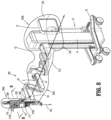
- drape 300 is positioned over surgical assembly 100, robotic arm 2, and handle portion 12 of cart 10, as shown in FIG. 8 .
- Sterile interface module 112 extends through first inlet 310a of drape 300 such that an upper portion of sterile interface module 112 resides within cavity 308 of first end portion 300a and a bottom portion of sterile interface module 112 is disposed outside of drape 300.
- the second inlet 310b of drape 300 is disposed adjacent a side portion of instrument drive unit 110 to align with openings 131 defined in instrument drive unit 110.
- Air flow "F" generated by, for example, fan 150, moves through second inlet 310b of drape 300 and into the cavity 308 of drape 300.
- air flow “F” moves through second inlet 310b of drape 300, it passes into cavity 308 via patch 319 such that substantially all of the moisture moving with air flow “F” is captured by patch 319 without entering cavity 308 of drape 300.
- the air flow “F” then travels into IDU 110 via openings 131 defined in IDU 110 and exits the IDU 110 via fan 150 to cool the internal components of IDU 110.
- the air flow "F,” now having absorbed heat generated by the working components of IDU 110 moves through conduit 312 of intermediate portion 300c of drape 300 and out of second end portion 300b of drape via outlet 318.
- air travels into drape 300 via both first and second inlets 310a, 310b and not just second inlet 310b.
- Drape 400 is similar to drape 300 except that in addition to having the patch 319 ( FIG. 9 ), or alternatively to having the patch 319, a first end portion 400a of drape 400 includes first and second overlapping flaps or baffles 432, 434 that cover an inlet 410b.
- First and second flaps 432, 434 extend from an outer surface 402 of drape 400.
- First flap 432 is fabricated from a harder, less flexible material than outer surface 402 of drape 400.
- first flap 432 may be fabricated from the same air permeable material as drape 400 or a more elastic/flexible material than drape 400.
- First flap 432 has a first end portion 432a connected to outer surface 402 of drape 400 at a location adjacent a first side of second inlet 410b.
- Inlet 410b has a perforated covering or section 419 that allows for air flow "F" to pass therethrough while prohibiting moisture from passing therethrough.
- inlet 410b may have a liquid resistant, air-permeable covering or may be covered with patch 319 or be devoid of any covering other than first and second flaps 432, 434.
- First flap 432 has a second or free end portion 432b that extends over inlet 410b while being spaced from outer surface 402 to define a first fluid pathway or channel "F1" that is substantially parallel with outer surface 402.
- Second flap 434 of drape 400 is similar to first flap 432 and has a first end portion 434a connected to outer surface 402 of drape wall 406 adjacent a second side of second inlet 410b, opposite the first side of second inlet 410b.
- Second flap 434 has a second or free end portion 434b that extends over second end portion 432b of first flap 432 while being spaced from second end portion 432b of first flap 432 to define a second fluid pathway or channel "F2" that is substantially parallel with first fluid pathway "F1.”
- First and second fluid pathways "F1," "F2" are in fluid communication with one another to allow for air to pass from second fluid pathway "F2," through first fluid pathway "F1,” and into cavity 408 of first end portion 400a via second inlet 410b.
- first end portion 400a of drape 400 may include first and second ribs 436, 438 disposed in, and extending parallel with, respective first and second pathways “F1," “F2" of second inlet 410b.
- ribs 436, 438 may extend at any suitable orientation relative to pathways “F1,” "F2" of second inlet 410b, such as, perpendicular.
- First and second ribs 436, 438 each have an elongated configuration and are narrower in width than a width of first and second fluid pathways "F 1," “F2” so as to not disrupt air flow through first and second pathways “F1,” “F2.”
- First rib 436 is disposed between outer surface 402 of first end portion 400a of drape 400 and first flap 432.
- Second rib 438 is attached to an inner surface of second flap 434 so as to be disposed between first and second flaps 432, 434.
- First and second ribs 436, 438 prevent and/or resist fluid pathways "F1," "F2” from collapsing by maintaining spacing between first and second flaps 432, 434, and first flap 432 and outer surface 402 of first end portion 400a of drape 400. It is contemplated that first and second ribs 436, 438 may be fabricated from a less flexible material than first and second flaps 432, 434.
- first and second pathways "F1,” “F2" of second inlet 410b may include a sponge/mesh, open-cell foams, springs, or tubes disposed therein, or opposing magnets disposed on opposite sides of flaps 432, 434.
- drape 400 is positioned over surgical assembly 100, robotic arm 2, and handle portion 12 of cart 10, as shown in FIG. 10 .
- Sterile interface module 112 extends through a first inlet 410a of drape 400 such that an upper portion of sterile interface module 112 resides within cavity 408 of first end portion 400a and a bottom portion of sterile interface module 112 is disposed outside of drape 400.
- the second inlet 410b of drape 400 is disposed adjacent a side portion of instrument drive unit 110 to align with openings 131 defined in instrument drive unit 110. Air flow "F” moves into second fluid pathway “F2" (from the sterile field), then through first fluid pathway "F1," and into cavity 408 of first end portion 400a via second inlet 410b.
- air flow "F” moves through second inlet 410b of drape 400, it passes into IDU 110 via openings 131 defined in IDU 110 and exits the IDU 110 via fan 150 to cool the internal components of IDU 110.
- air flow “F” may first travel into IDU 110 via fan 150 and exit through openings 131 of IDU 110 or other openings of IDU 110.
- the air flow "F,” now having absorbed heat generated by the working components of IDU 110, moves through a conduit 312 of intermediate portion 400c of drape 400 and out of a second end portion 400b of drape via an outlet 418 of second end portion 400b and out into the non-sterile field.
- air travels into drape 400 via both first and second inlets 410a, 410b and not just second inlet 410b.
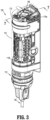
- surgical assembly 100 of surgical system 1 which is configured to be coupled with or to robotic arm 2 or 3 ( FIG. 2 ), generally includes the IDU 110, the sterile interface module 112, and the electromechanical surgical instrument 130 ( FIG. 2 ).
- IDU 110 transfers power and actuation forces from its motors 114 to driven members (not shown) of electromechanical surgical instrument 130 to ultimately drive movement of components of the end effector of electromechanical surgical instrument 130, for example, a movement of a knife blade (not shown) and/or a closing and opening of jaw members of the end effector, the actuation or firing of a stapler, and/or the activation or firing of an electrosurgical energy-based instrument, or the like.
- Motor assembly 114 of IDU 110 is rotated by a motor "M" disposed in IDU 110 and transfers its rotational motion to electromechanical surgical instrument 130.
- IDU 110 includes a housing cover 113 coupled to rail 40 of surgical robotic arm 2.
- Housing cover 113 of IDU 110 enshrouds, covers, and protects the inner components of IDU 110.
- Housing cover 113 of IDU 110 may have a generally cylindrical configuration, but in some embodiments, housing cover 113 may assume a variety of configurations, such as, for example, square, triangular, elongate, curved, semi-cylindrical or the like.
- housing cover 113 protects or shields various components of IDU 110 including motor assembly 114 and a flex spool assembly 160 that transfers power and data to components of IDU 110.
- Motor assembly 114 of IDU 110 may include four motors, for example, canister motors or the like, each having a drive shaft 121 configured to interface with corresponding drives 185 ( FIG. 17A ) of sterile interface module 112. While IDU 110 is illustrated as having four motors, it is contemplated that IDU 110 may include any suitable number of motors.
- Drive shafts 121 of IDU 110 have non-circular transverse cross-sectional profiles (e.g., substantially D-shaped, or the like).
- the four motors of motor assembly 114 are arranged in a rectangular formation such that the respective drive shafts 121 thereof are all parallel with one another and all extending in a common direction.
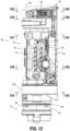
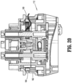
- IDU 110 defines a plurality inlets or openings 117 in a bottom portion 110b thereof. Openings 117 of IDU 110 are in fluid communication with corresponding channels 180 ( FIG. 17A-17C ) defined in sterile interface module 112 such that air passes from sterile interface module 112 into IDU 110 via openings 117 of IDU 110.
- IDU 110 defines a plurality of channels 119 ( FIGS. 15A-15C ) extending longitudinally between opposite ends 110a, 110b of IDU 110. In particular, channels 119 are in fluid communication with openings 117 defined in bottom portion 110b of IDU 110 and terminate adjacent a fan 150 of IDU 110 located at a top portion 110a of IDU 110.
- Channels 119 are disposed between motors of motor assembly 114 to provide passage of air therethrough to cool the motor assembly 114.
- Channels 119 also extend alongside elongate flex circuit boards 127 of IDU and a nexus 129 of IDU 110 to provide an ingress for heat generated by elongated flex circuit boards 127 and the nexus 129 that connects with elongated flex circuit boards 127.
- Channels 119 terminate within a central cavity 162 defined in flex spool assembly 160 such that air can pass through central cavity 162 to cool flex spool assembly 160.
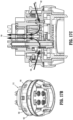
- IDU 110 includes a fan 150 disposed within the top portion or proximal end portion 110a thereof, and is located above flex spool assembly 160.
- Fan 150 is a radial blower fan, as shown in FIG. 16A .
- fan 150 may be in the form of an axial fan. It is contemplated that any other suitable fans may be used, such as, for example, centrifugal fans, diaphragm or piston actuated air pumps, peristaltic pumps, thermal chimney, centrifugal pumps, venturi pumps implemented via an air compressor, or the like.
- Fan 150 sits atop flex spool assembly 160 and is in fluid communication with central cavity 162 of flex spool assembly 160 such that fan 150 receives or draws air from central cavity 162 of flex spool assembly 160 such that the air passes through channels 119 of IDU 110. Fan 150 generates negative pressure within cavity 208 of first end portion 200a of drape 200 to draw air into drape 200.
- Fan 150 may be coupled to or be in communication with a processor, for example, control device 4 ( FIG. 1 ). Fan 150 may also be in communication with temperature sensors, integrated circuits, central processing units, motors, resistors, strain gauges, thermistors, or pressure sensors disposed within any of the components of surgical assembly 100 or in drapes 200, 300, or 400.
- Control device 4 is configured to adjust a speed of fan 150 based on an orientation of robotic arm 2. For example, if robotic arm 2 is in a collapsed state in which robotic arm 2 has a reduced overall length, speed of fan 150 may be reduced due to a decreased distance air travels through one of drapes 200, 300, or 400.
- control device 4 can detect whether robotic arm 2 is in its collapsed or extended states using strain gauges attached at the joints of robotic arm 2.
- Control device 4 may also be configured to adjust the speed of fan 150 based on the pressure or temperature sensed by pressure and temperature sensors. For example, the speed of fan 150 may be increased as temperature in drape 200, 300, or 400 increases and the speed of fan 150 may be decreased with a decrease in temperature. In some embodiments, the speed of fan 150 may also be adjusted based on the ambient temperature outside of drape 200, 300, or 400.
- the control device 4 can measure the temperature within the drapes 200, 300, or 400 using various sensors that provide feedback to control device 4 about various conditions of the drape. For example, drapes 200, 300, 400 may include thermal sensors disposed at various portions of drapes 200, 300, or 400.
- control device 4 may be in communication with sensors that sense the temperature of, or measure the current/power used by, components of surgical assembly 100, such as, for example, microprocessors, integrated components, motor controllers, sense resistors, strain gauges, or motor windings.
- a top portion 113a of housing cover 113 may define a plurality of vents or slits 152 therein to allow for air to transfer out of IDU 110.
- Fan 150 is configured to generate negative pressure, which draws air through sterile interface module 112, into channels 119 defined in IDU 110, through motor assembly 114 and then flex spool assembly 160 and out of top portion 113a of housing cover 113 through slits 152 to cool electronics during operation thereof, and to maintain a constant negative pressure through IDU 110.
- surgical assembly 100 may further include a sterile interface module 112 for selectively interconnecting the IDU 110 and the electromechanical surgical instrument 130.
- the electromechanical surgical instrument 130 may be laterally coupled (e.g., side-loaded) to, or laterally decoupled from, the sterile interface module 112 of the robotic surgical assembly 100.
- the sterile interface module 112 functions to provide an interface between the bottom portion 110b (i.e., distal end) of instrument drive unit 110 and an electromechanical surgical instrument such as electromechanical surgical instrument 130.
- This interface advantageously maintains sterility, provides a means to transmit electrical communication between the IDU 110 and the electromechanical surgical instrument 130, provides structure configured to transfer rotational force from the IDU 110 to the electromechanical surgical instrument 130 for performing a function with the electromechanical surgical instrument 130, and/or provides structure to selectively attach/remove the electromechanical surgical instrument 130 to/from the IDU 110 (e.g., for rapid instrument exchange).
- Sterile interface module 112 defines a plurality of openings 180 in a collar 182 thereof 112. Openings 180 are disposed circumferentially around collar 182 of sterile interface module 112. Collar 182 is configured to protrude distally from inlet 210 of drape 200, first inlet 310a of drape 300, or first inlet 410a of drape 400, so that air can pass into openings 180 of sterile interface module 112 and into drape 200, 300, or 400, depending on which drape is used.
- Sterile interface module 112 includes a central passageway 184 defined through a proximal surface thereof and is in fluid communication with openings 180 of sterile interface module 112. Central passageway 184 has a key-shaped configuration to assist in alignment and in defining a mating direction with bottom portion 110b of IDU 110. In some embodiments, central passageway 184 may assume any suitable symbolic shape.
- openings 117 defined through bottom portion 110b of IDU 110 are in fluid communication with central passageway 184 of sterile interface module 112.
- air may be passed from outside of drape 200, 300, or 400, into sterile interface module 112 via openings 180 of sterile interface module 112, and into IDU 110 via openings 117 of IDU to cool the internal components of IDU 110, for example, motor assembly 114, elongated flex circuit boards 127, nexus 129, and/or flex spool assembly 160.
- proximal portion 42 of surgical robotic arm 2 is coupled to cart 10, and instrument drive unit 110, having sterile interface module 112 attached thereto, is coupled to slide rail 40 of surgical robotic arm 2.
- instrument drive unit 110 having sterile interface module 112 attached thereto, is coupled to slide rail 40 of surgical robotic arm 2.
- Any of the drapes 200, 300, 400 described herein may be used to cover surgical robotic assembly 100, robotic arm 2, and cart 10.
- drape 300 may be used to cover surgical assembly 100 (e.g., IDU 110, and a top portion of sterile interface module 112), surgical robotic arm 2, and handle portion 12 of cart 10.
- outlet 318 of second end portion 300b of drape 300 is placed over surgical assembly 100 and pulled in a proximal direction to position surgical assembly 100, including slide rail 40, in cavity 308 of first end portion 300a, and elongate members 2a, 2b, 2c of surgical robotic arm 2 in conduit 312 of intermediate portion 300c of drape 300.
- Proximal movement of drape 300 along surgical robotic arm 2 is continued until the elastic band, draw string, hook and loop fastener, draw string, cinch line, bungee hooks, magnetic material, or the like, of second end portion 300b of drape 300 is passed over handle portion 12 of cart 10, thereby disposing handle portion 12 of cart 10 in cavity 316 of second end portion 300b of drape 300.
- collar 182 of sterile interface module 112 is passed through first inlet 310a of first end portion 300a of drape 300 to expose openings 180 defined in sterile interface module 112 to an environment exterior to drape 300.
- First inlet 310a of drape 300 is secured to sterile interface module 112 using a ring, for example, a plastic ring (not explicitly shown), provided in drape 300 that surrounds first inlet 310a or using an elastic band, hook and loop fastener, cinch line, bungee hooks, magnetic material, or the like that surrounds first inlet 310a.
- the ring of drape 300 allows for sterile interface module 112 to rotate relative to and within first inlet 310a of drape 300 while maintaining sterile interface module 112 axially fixed therein.
- Second end portion 300b of drape 300 may be secured to cart 10 by allowing the inwardly-oriented bias of the elastic band of second end portion 300b of drape 300 to engage handle portion 12 of cart 10 or by tightening a tie cord of second end portion 300b of drape 300 around post 14 of cart 10, depending on whether second end portion 300b of drape 300 has an elastic band and/or a tie cord.
- surgical instrument 130 may be attached to sterile interface module 112.
- fan 150 of IDU 110 and/or a fan of cart 10 may be activated to create an air pathway or negative pressure through drape 300.
- the fan 150 of IDU 110 initially creates a negative pressure in channels 119 of IDU 110, which drives air into openings 180 defined in collar 182 of sterile interface module 112.
- the air travels through openings 180 of sterile interface module 112, and into channels 119 of IDU 110 via central passageway 184 of sterile interface module 112.
- the air passes through first inlet 310a of drape 300.
- air may also be passed into drape 300 via second inlet 310b.
- air may also be passed into drape 300 via second inlet 310b.
- a negative pressure is created in channels 119 driving air into IDU 110 through side openings 131 defined in housing 113 of IDU 110 via first and second fluid pathways "F1," "F2" of second inlet 310b.
- IDU 110 Upon air entering channels 119 of IDU 110, the air in IDU 110 absorbs heat generated by the internal components of IDU 110 (e.g., motor assembly 114, circuit boards 127, nexus 129, flex spool assembly 160, etc.) and out of IDU 110 via vents 152 of IDU 110.
- a fan of cart 10, a fan of robotic surgical arm 2, and/or a fan of second end portion 300b of drape 300 may also be activated to draw the warmed air away from cavity 308 of first end portion 300a of drape 300, through conduit 312 of intermediate portion 300c of drape 300, and out of second end portion 300b of drape 300 via outlet 318 of drape 300.
- IDU 110 If the internal components of IDU 110 reach a temperature above a threshold temperature, fan 150 of IDU 110 and/or any other fans attached to drape 300, robotic arm 2, or cart 10 may be increased in speed to cause air to flow at a faster rate through drape 300. Due to the fluid pathways defined through IDU 110 taking a tortuous pathway (e.g., twisting, turning, and generally non-linear) therethrough, it is possible for air to pass therethrough while preventing liquids from passing therethrough.
- tortuous pathway e.g., twisting, turning, and generally non-linear
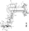
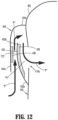
- Drape 500 of FIG. 21 differs from the other drapes 200, 300, and 400 of the present disclosure by having a tubular member, such as, for example, a hose 520 extending along a length thereof.
- Hose 520 is configured to facilitate movement of warmed air from a first end portion 500a of drape 500 toward a second end portion 500b of drape 500 and out of drape 500.
- Drape 500 includes a drape wall 506 having an outer surface 502 and an inner surface 504.
- the inner surface 504 at a first end portion 500a of drape 500 defines a cavity 508 therein.
- Cavity 508 of first end portion 500a of drape 500 is dimensioned to receive or encapsulate surgical assembly 100 (e.g., instrument drive unit 110 and slide rail 40).
- First end portion 500a of drape 500 defines an inlet or channel 510 extending through the outer surface 502 and the inner surface 504 of drape 500.
- Inlet 510 is in fluid communication with cavity 508 of first end portion 500a.
- inlet 510 provides ingress of air flow into drape 500 to cool components of surgical assembly 500.
- Inlet 510 has a generally circular or annular shape dimensioned to form a seal with sterile interface module 112 of surgical assembly 100.
- Intermediate portion 500c of drape 500 is dimensioned to encapsulate or house elongate members 2a, 2b, 2c of surgical robotic arm 2.
- intermediate portion 500c of drape 500 defines an elongated conduit 512 extending longitudinally therethrough and dimensioned for receipt of a surgical robotic arm, for example, robotic arm 2.
- Conduit 512 of intermediate portion 500c has a length dimensioned to accommodate robotic arm 2, in embodiments to accommodate at least an entire length of robotic arm 2 when robotic arm 2 has each of its elongate members 2a, 2b, 2c in an extended state.
- Second end portion 500b of drape 500 defines a cavity 516 therein. Cavity 516 of second end portion 500b is dimensioned to receive or encapsulate at least proximal portion 42 of robotic arm 2 and/or a portion or portions of robotic cart 10. Second end portion 500b of drape 500 has an outlet 518 extending through drape wall 506 of drape 500. As such, outlet 518 of second end portion 500b is in fluid communication with cavity 516 of second end portion 500b of drape 500. Outlet 518 of drape 500 has a generally circular or annular shape dimensioned to fit over handle portion 12 of cart 10 or cart 10 in its entirety.
- drape 500 has a hose 520 integrated into drape wall 506 and running along a length thereof.
- Hose 520 is configured for passing air that has been warmed during operation of surgical assembly 100 (e.g., IDU 110) from first end portion 500a of drape 500 and out of drape 500 via outlet 518 at second end portion 500b.
- Hose 520 may be fabricated from a thermally-conductive material, such as, for example, woven metals, graphite, copper, or aluminum, to facilitate the transfer of heat out of drape 500.
- Hose 520 has a distal opening 520a and a proximal opening 520b and a central passageway (not explicitly shown) extending therebetween.
- Distal opening 520a of hose 520 is disposed within cavity 508 of first end portion 500a of drape 500 and proximal opening 520b is disposed outside of drape 500 adjacent second end portion 500b of drape 500.
- proximal and distal openings 520a, 520b of hose 520 may be disposed at various locations of drape 500, for example, proximal opening 520b of hose 520 may be disposed within cavity 516 of second end portion 500b of drape 500 rather than outside of cavity 516.
- Distal opening 520a may be fitted onto fan 150 of IDU 110 such that air is pulled by and through fan 150 and into hose 520 via distal opening 520a.
- Hose 520 of drape 500 may be attached to various portions of surgical assembly 100, robotic arm 2, and robotic arm cart 10 so that hose 520 travels along each of the portions of surgical assembly 100, robotic arm 2, and robotic arm cart 10, and moving heat away from each.
- hose 520 may be attached to these components of surgical system 1 using a hook and loop fastener, clips, magnetic material, or the like.
- hose 520 instead of hose 520 being integrated into drape wall 506 of drape, hose 520 may be separate and apart from drape 520 and be attached to various portions of surgical assembly 100, robotic arm 2, and robotic arm cart 10 prior to these components being covered with drape 500.
- Hose 520 may be configured to be coupled at proximal opening 520b thereof with a vacuum/pump 525 (e.g., any of the pumps/vacuums described above) for pulling air through hose 520.
- hose 520 may include an air hose plug 527 fluidly coupled to proximal opening 520b of hose 520 for coupling to an auxiliary air hose 529 extending from the vacuum/pump 525.
- Vacuum/pump 525 may be supported on cart 10 and disposed outside of drape 500. When air hose 529 is attached to air hose plug 525 of hose 520, an activation of vacuum/pump 525 will draw air through hose 520 to carry hot air that builds up in drape 500 out of drape 500.
Landscapes
- Health & Medical Sciences (AREA)
- Surgery (AREA)
- Life Sciences & Earth Sciences (AREA)
- Engineering & Computer Science (AREA)
- Animal Behavior & Ethology (AREA)
- Heart & Thoracic Surgery (AREA)
- Medical Informatics (AREA)
- Molecular Biology (AREA)
- Biomedical Technology (AREA)
- General Health & Medical Sciences (AREA)
- Public Health (AREA)
- Veterinary Medicine (AREA)
- Robotics (AREA)
- Nuclear Medicine, Radiotherapy & Molecular Imaging (AREA)
- Mechanical Engineering (AREA)
- Manipulator (AREA)
Claims (14)
- Drap (300, 400) pour recouvrir un système chirurgical robotisé (100), le drap comprenant :une première partie d'extrémité (300a, 400a) ayant une surface externe et une surface interne et définissant une entrée (310a, 310b, 410a, 410b) à travers les surfaces externe et interne, la première partie d'extrémité définissant une cavité (308, 408) à l'intérieur de celle-ci dimensionnée pour recevoir une unité d'entraînement d'instrument (110) et étant en communication fluidique avec l'entrée ;une seconde partie d'extrémité (300b, 400b) ayant une surface externe et une surface interne et définissant une sortie (318, 418) à travers les surfaces externe et interne de la seconde partie d'extrémité, la seconde partie d'extrémité définissant une cavité (316, 416) à l'intérieur de celle-ci et étant en communication fluidique avec la sortie ; etune partie intermédiaire (300c, 400c) s'étendant entre les première et seconde parties et définissant un conduit allongé à travers celle-ci dimensionné pour recevoir un bras robotisé chirurgical (2), caractérisé en ce que l'entrée comporte une première entrée (310a, 410a) et une seconde entrée (310b, 410b) ; et la première partie d'extrémité (200a) comporte un rapiècement (319, 419) recouvrant la seconde entrée, le rapiècement étant formé à partir d'un matériau perméable à l'air, résistant aux liquides pour permettre l'admission d'air à travers la seconde entrée.
- Drap selon la revendication 1, dans lequel la première entrée (310a, 410a) est annulaire et dimensionnée pour entourer une partie distale d'une unité d'entraînement d'instrument (110).
- Drap selon l'une quelconque revendication précédente, dans lequel la première partie d'extrémité comporte :un premier rabat (432) s'étendant à partir de la surface externe de la première partie d'extrémité (400a) et chevauchant l'entrée pour définir une première partie d'une voie de passage de fluide ; etun second rabat (434) s'étendant à partir de la surface externe de la première partie d'extrémité et chevauchant le premier rabat (432) pour définir une seconde partie de la voie de passage de fluide ;de préférence dans lequel les première et seconde parties de la voie de passage de fluide sont parallèles l'une à l'autre et en communication fluidique l'une avec l'autre.
- Drap selon la revendication 3, dans lequel la première partie d'extrémité comporte :une première côte (436) disposée dans et s'étendant en parallèle à la première partie de la voie de passage de fluide pour maintenir un espacement entre le premier rabat et la surface externe ; etune seconde côte (438) disposée dans et s'étendant en parallèle à la seconde partie de la voie de passage de fluide pour maintenir un espacement entre les premier et second rabats.
- Système chirurgical robotisé, comprenant :un bras robotisé chirurgical (2) ayant une première partie d'extrémité et une seconde partie d'extrémité ;un ensemble chirurgical couplé à la première partie d'extrémité du bras robotisé chirurgical, l'ensemble chirurgical comprenant une unité d'entraînement d'instrument (110) ; etle drap (300, 400) selon l'une quelconque revendication précédente.
- Système chirurgical robotisé selon la revendication 5, dans lequel l'ensemble chirurgical comporte un ventilateur (150) configuré pour aspirer de l'air à partir d'un champ stérile d'une chirurgie, à travers les entrées du drap, dans l'ensemble chirurgical, hors du drap à travers la sortie de celui-ci, et loin du champ stérile de la chirurgie.
- Système chirurgical robotisé selon la revendication 6, comprenant en outre un dispositif de commande (4) en communication avec le ventilateur (150) et configuré pour ajuster une vitesse du ventilateur en fonction d'une orientation du bras robotisé ; de préférence dans lequel le dispositif de commande est configuré pour ajuster la vitesse du ventilateur à l'aide de mesures prises par des jauges de contrainte couplées au niveau d'articulations du bras robotisé chirurgical.
- Système chirurgical robotisé selon la revendication 7, dans lequel la seconde partie d'extrémité du drap définit un évent (220)
à travers les surfaces externe et interne de celui-ci ; de préférence dans lequel le dispositif de commande (4) est en outre configuré pour faire changer l'évent entre des configurations ouverte et fermée en fonction d'au moins l'une d'une température à l'intérieur du drap ou de la vitesse du ventilateur. - Système chirurgical robotisé selon l'une quelconque des revendications 6 à 8, dans lequel l'unité d'entraînement d'instrument comporte une première partie d'extrémité et une seconde partie d'extrémité, le ventilateur (150) étant attaché à la première partie d'extrémité.
- Système chirurgical robotisé selon la revendication 9, comprenant en outre un module d'interface stérile (112) couplé à la seconde partie d'extrémité de l'unité d'entraînement d'instrument (110), au moins une partie du module d'interface stérile étant configurée pour être entourée par la première entrée (310a, 410a) du drap pour permettre à de l'air de passer dans la cavité de la première partie d'extrémité du drap par l'intermédiaire du module d'interface stérile ; et/ou dans lequel l'unité d'entraînement d'instrument (110) a une pluralité de canaux de fluide s'étendant de la première partie d'extrémité de l'unité d'entraînement d'instrument à la seconde partie d'extrémité de l'unité d'entraînement d'instrument, la pluralité de canaux de fluide empruntant une voie de passage tortueuse à travers l'unité d'entraînement d'instrument de telle sorte que l'admission de liquides est empêchée et l'admission d'air est autorisée.
- Système chirurgical robotisé selon l'une quelconque des revendications 5 à 10, comprenant en outre un chariot robotisé (10) ayant une première partie d'extrémité et une seconde partie d'extrémité, dans lequel la cavité de la seconde partie d'extrémité du drap est dimensionnée pour recevoir au moins l'une des première ou seconde parties d'extrémité du chariot robotisé ; de préférence dans lequel le chariot robotisé a un ventilateur qui dirige le flux d'air dans une direction allant de la première partie d'extrémité du drap vers la seconde partie d'extrémité du drap à travers le conduit du drap.
- Système chirurgical robotisé selon l'une quelconque des revendications 5 à 11, dans lequel le drap comporte au moins une côte conductrice allongée (214) s'étendant le long d'une surface interne de la partie intermédiaire du drap.
- Système chirurgical robotisé selon l'une quelconque des revendications 5 à 9, dans lequel la première entrée (310a, 410a) du drap est annulaire et dimensionnée pour entourer une partie d'extrémité distale d'un module d'interface stérile de l'ensemble chirurgical.
- Système chirurgical robotisé selon l'une quelconque des revendications 5 à 13, dans lequel le drap comporte un élément tubulaire s'étendant le long de la partie intermédiaire de celui-ci et ayant une ouverture proximale disposée à l'intérieur de la première partie d'extrémité du drap et une ouverture distale disposée adjacente à la seconde partie d'extrémité du drap de telle sorte que de l'air se déplace dans l'élément tubulaire à partir de la première partie d'extrémité du drap par l'intermédiaire de l'ouverture proximale et sort de l'élément tubulaire par l'intermédiaire de l'ouverture distale.
Applications Claiming Priority (2)
| Application Number | Priority Date | Filing Date | Title |
|---|---|---|---|
| US201762510883P | 2017-05-25 | 2017-05-25 | |
| PCT/US2018/031301 WO2018217430A1 (fr) | 2017-05-25 | 2018-05-07 | Systèmes chirurgicaux robotiques et drapés pour recouvrir des composants de systèmes chirurgicaux robotiques |
Publications (3)
| Publication Number | Publication Date |
|---|---|
| EP3629983A1 EP3629983A1 (fr) | 2020-04-08 |
| EP3629983A4 EP3629983A4 (fr) | 2021-03-03 |
| EP3629983B1 true EP3629983B1 (fr) | 2023-06-28 |
Family
ID=64395852
Family Applications (1)
| Application Number | Title | Priority Date | Filing Date |
|---|---|---|---|
| EP18805856.4A Active EP3629983B1 (fr) | 2017-05-25 | 2018-05-07 | Systèmes chirurgicaux robotiques et drapés pour recouvrir des composants de systèmes chirurgicaux robotiques |
Country Status (5)
| Country | Link |
|---|---|
| US (1) | US11510747B2 (fr) |
| EP (1) | EP3629983B1 (fr) |
| JP (1) | JP2020520694A (fr) |
| CN (1) | CN110621255B (fr) |
| WO (1) | WO2018217430A1 (fr) |
Families Citing this family (29)
| Publication number | Priority date | Publication date | Assignee | Title |
|---|---|---|---|---|
| US20140005640A1 (en) | 2012-06-28 | 2014-01-02 | Ethicon Endo-Surgery, Inc. | Surgical end effector jaw and electrode configurations |
| WO2018144654A1 (fr) * | 2017-01-31 | 2018-08-09 | Transenterix Surgical, Inc. | Système d'entraînement d'instrument hydraulique pour chirurgie mini-invasive |
| US11628029B2 (en) | 2017-09-13 | 2023-04-18 | Intuitive Surgical Operations, Inc. | Surgical drape cooling |
| US11096754B2 (en) | 2017-10-04 | 2021-08-24 | Mako Surgical Corp. | Sterile drape assembly for surgical robot |
| WO2019108567A1 (fr) | 2017-12-01 | 2019-06-06 | Covidien Lp | Ensemble de gestion de champ destiné à des systèmes chirurgicaux robotisés |
| EP3737328B1 (fr) * | 2018-01-09 | 2025-04-30 | Covidien LP | Module d'interface stérile pour ensembles chirurgicaux robotisés |
| GB2597885B8 (en) * | 2018-01-30 | 2023-08-30 | Cmr Surgical Ltd | Surgical drape |
| GB2598877B8 (en) * | 2018-01-30 | 2023-08-30 | Cmr Surgical Ltd | Surgical drape |
| GB2570514B8 (en) * | 2018-01-30 | 2023-06-07 | Cmr Surgical Ltd | Surgical drape |
| DE102018206009A1 (de) * | 2018-04-19 | 2019-10-24 | Kuka Deutschland Gmbh | Roboteranordnung |
| WO2020060794A1 (fr) * | 2018-09-17 | 2020-03-26 | Covidien Lp | Systèmes robotisés chirurgicaux |
| US11376082B2 (en) | 2019-06-27 | 2022-07-05 | Cilag Gmbh International | Robotic surgical system with local sensing of functional parameters based on measurements of multiple physical inputs |
| EP4021336A4 (fr) * | 2019-08-28 | 2023-09-20 | Covidien LP | Systèmes chirurgicaux robotisés et drapés pour recouvrir des éléments de systèmes chirurgicaux robotisés |
| GB202000992D0 (en) * | 2020-01-23 | 2020-03-11 | King S College London | Actuation system for tubes of a robotic tool |
| WO2021240296A1 (fr) * | 2020-05-28 | 2021-12-02 | Mazor Robotics Ltd. | Système et procédé de commande de volume de champ opératoire |
| CN113069213B (zh) * | 2021-02-23 | 2023-12-01 | 深圳康诺思腾科技有限公司 | 无菌围帘及具有其的手术机器人组件 |
| DE102021108188B4 (de) | 2021-03-31 | 2022-11-10 | Alpaka Technology UG (haftungsbeschränkt) | Video-Endoskop sowie Verfahren zur Überwachung einer Sterilbarriere eines Video-Endoskops |
| US11931026B2 (en) | 2021-06-30 | 2024-03-19 | Cilag Gmbh International | Staple cartridge replacement |
| US11974829B2 (en) | 2021-06-30 | 2024-05-07 | Cilag Gmbh International | Link-driven articulation device for a surgical device |
| US12358136B2 (en) | 2021-06-30 | 2025-07-15 | Cilag Gmbh International | Grasping work determination and indications thereof |
| CN113520606B (zh) * | 2021-08-11 | 2023-03-24 | 上海微创医疗机器人(集团)股份有限公司 | 无菌板组件、手术机器人及手术机器人系统 |
| EP4387554A1 (fr) * | 2021-08-20 | 2024-06-26 | Titan Medical Inc. | Système de chirurgie robotique |
| EP4486242A1 (fr) | 2022-03-02 | 2025-01-08 | MAKO Surgical Corp. | Système robotique comprenant un dispositif de suivi de liaison |
| EP4265216A1 (fr) * | 2022-04-21 | 2023-10-25 | Microsure B.V. | Bras de robot destiné à être utilisé en chirurgie, microchirurgie ou super-microchirurgie |
| WO2024067335A1 (fr) * | 2022-09-30 | 2024-04-04 | 深圳市精锋医疗科技股份有限公司 | Appareil d'actionnement de robot médical et robot de cathéter |
| CN117838301A (zh) * | 2022-09-30 | 2024-04-09 | 深圳市精锋医疗科技股份有限公司 | 一种医疗机器人的驱动装置及导管机器人 |
| CN117838313A (zh) * | 2022-09-30 | 2024-04-09 | 深圳市精锋医疗科技股份有限公司 | 一种医疗机器人的驱动装置及导管机器人 |
| JP2024068319A (ja) * | 2022-11-08 | 2024-05-20 | セイコーエプソン株式会社 | ロボット |
| DE102023110099A1 (de) * | 2023-04-20 | 2024-10-24 | avateramedical GmBH | Sterilabdeckung einer Robotereinheit zur robotergestützten Chirurgie |
Family Cites Families (222)
| Publication number | Priority date | Publication date | Assignee | Title |
|---|---|---|---|---|
| US3528720A (en) | 1968-12-18 | 1970-09-15 | Richards Mfg Co | Operating microscope envelope means |
| US3540441A (en) | 1969-03-05 | 1970-11-17 | Kendall & Co | Surgical drape with hand receiving cuff |
| US3777749A (en) | 1969-10-01 | 1973-12-11 | Kendall & Co | Folded surgical drape |
| US3707964A (en) | 1970-06-20 | 1973-01-02 | Kendall & Co | Surgical drape with hand receiving cuff having internal stop guides |
| US3747655A (en) | 1971-03-19 | 1973-07-24 | Becton Dickinson Co | Disposable mayo stand cover |
| US3955569A (en) | 1975-01-29 | 1976-05-11 | Johnson & Johnson | Surgical drape |
| US3952738A (en) | 1975-01-29 | 1976-04-27 | Johnson & Johnson | Folded surgical drape |
| US4183613A (en) * | 1978-09-13 | 1980-01-15 | Xomed, Inc. | Microscope drape and method of making same |
| US4457026A (en) | 1983-09-30 | 1984-07-03 | Surgikos, Inc. | Surgical head drape |
| WO1985001496A1 (fr) | 1983-10-03 | 1985-04-11 | American Telephone & Telegraph Company | Housse de protection pour robot |
| US4919112B1 (en) | 1989-04-07 | 1993-12-28 | Low-cost semi-disposable endoscope | |
| JP2988980B2 (ja) | 1989-10-23 | 1999-12-13 | オリンパス光学工業株式会社 | 手術用顕微鏡 |
| JP2988981B2 (ja) | 1990-08-08 | 1999-12-13 | オリンパス光学工業株式会社 | 手術用顕微鏡用ドレープ |
| US5122904A (en) * | 1989-10-23 | 1992-06-16 | Olympus Optical Co., Ltd. | Operating microscope with drape and suction means for removing air from the drape |
| US5522403A (en) | 1991-09-16 | 1996-06-04 | Microtek Medical, Inc. | Splash shield |
| US5762458A (en) | 1996-02-20 | 1998-06-09 | Computer Motion, Inc. | Method and apparatus for performing minimally invasive cardiac procedures |
| US5860420A (en) | 1994-03-03 | 1999-01-19 | Rotecno Ag | Surgical draping system having a reusable and a disposable component |
| US5515868A (en) | 1994-07-05 | 1996-05-14 | Standard Textile Co., Inc. | Surgical drape having at least one openable and reclosable slit formed therein |
| US5740699A (en) | 1995-04-06 | 1998-04-21 | Spar Aerospace Limited | Wrist joint which is longitudinally extendible |
| US5855583A (en) | 1996-02-20 | 1999-01-05 | Computer Motion, Inc. | Method and apparatus for performing minimally invasive cardiac procedures |
| US5792135A (en) | 1996-05-20 | 1998-08-11 | Intuitive Surgical, Inc. | Articulated surgical instrument for performing minimally invasive surgery with enhanced dexterity and sensitivity |
| US5957831A (en) * | 1996-07-12 | 1999-09-28 | Adair; Edwin L. | Sterile encapsulated endoscopic video monitor |
| US6364888B1 (en) | 1996-09-09 | 2002-04-02 | Intuitive Surgical, Inc. | Alignment of master and slave in a minimally invasive surgical apparatus |
| US7699855B2 (en) | 1996-12-12 | 2010-04-20 | Intuitive Surgical Operations, Inc. | Sterile surgical adaptor |
| US7727244B2 (en) * | 1997-11-21 | 2010-06-01 | Intuitive Surgical Operation, Inc. | Sterile surgical drape |
| US8529582B2 (en) | 1996-12-12 | 2013-09-10 | Intuitive Surgical Operations, Inc. | Instrument interface of a robotic surgical system |
| US6331181B1 (en) | 1998-12-08 | 2001-12-18 | Intuitive Surgical, Inc. | Surgical robotic tools, data architecture, and use |
| US7963913B2 (en) | 1996-12-12 | 2011-06-21 | Intuitive Surgical Operations, Inc. | Instrument interface of a robotic surgical system |
| US6132368A (en) | 1996-12-12 | 2000-10-17 | Intuitive Surgical, Inc. | Multi-component telepresence system and method |
| US7666191B2 (en) | 1996-12-12 | 2010-02-23 | Intuitive Surgical, Inc. | Robotic surgical system with sterile surgical adaptor |
| US8182469B2 (en) | 1997-11-21 | 2012-05-22 | Intuitive Surgical Operations, Inc. | Surgical accessory clamp and method |
| US8206406B2 (en) | 1996-12-12 | 2012-06-26 | Intuitive Surgical Operations, Inc. | Disposable sterile surgical adaptor |
| AUPO478397A0 (en) | 1997-01-31 | 1997-02-20 | Fairmont Medical Products Pty Ltd | Endoscopic drape |
| US6105578A (en) | 1997-02-27 | 2000-08-22 | Kimberly-Clark Worldwide, Inc. | Equipment drape for use with an interventional magnetic resonance imaging device |
| US6714839B2 (en) | 1998-12-08 | 2004-03-30 | Intuitive Surgical, Inc. | Master having redundant degrees of freedom |
| US6116741A (en) | 1998-03-13 | 2000-09-12 | Deka Medical, Incorporated | Surgical microscope operating drape and methods of operation and manufacture thereof |
| US6246200B1 (en) | 1998-08-04 | 2001-06-12 | Intuitive Surgical, Inc. | Manipulator positioning linkage for robotic surgery |
| GB9823492D0 (en) | 1998-10-27 | 1998-12-23 | Amba Med Ltd | Drape |
| US6951535B2 (en) | 2002-01-16 | 2005-10-04 | Intuitive Surgical, Inc. | Tele-medicine system that transmits an entire state of a subsystem |
| US6459926B1 (en) | 1998-11-20 | 2002-10-01 | Intuitive Surgical, Inc. | Repositioning and reorientation of master/slave relationship in minimally invasive telesurgery |
| US8600551B2 (en) | 1998-11-20 | 2013-12-03 | Intuitive Surgical Operations, Inc. | Medical robotic system with operatively couplable simulator unit for surgeon training |
| US6659939B2 (en) | 1998-11-20 | 2003-12-09 | Intuitive Surgical, Inc. | Cooperative minimally invasive telesurgical system |
| US6493608B1 (en) | 1999-04-07 | 2002-12-10 | Intuitive Surgical, Inc. | Aspects of a control system of a minimally invasive surgical apparatus |
| US7125403B2 (en) | 1998-12-08 | 2006-10-24 | Intuitive Surgical | In vivo accessories for minimally invasive robotic surgery |
| US6770081B1 (en) | 2000-01-07 | 2004-08-03 | Intuitive Surgical, Inc. | In vivo accessories for minimally invasive robotic surgery and methods |
| US6799065B1 (en) | 1998-12-08 | 2004-09-28 | Intuitive Surgical, Inc. | Image shifting apparatus and method for a telerobotic system |
| US6394998B1 (en) | 1999-01-22 | 2002-05-28 | Intuitive Surgical, Inc. | Surgical tools for use in minimally invasive telesurgical applications |
| US6424885B1 (en) | 1999-04-07 | 2002-07-23 | Intuitive Surgical, Inc. | Camera referenced control in a minimally invasive surgical apparatus |
| US6594552B1 (en) | 1999-04-07 | 2003-07-15 | Intuitive Surgical, Inc. | Grip strength with tactile feedback for robotic surgery |
| US8944070B2 (en) | 1999-04-07 | 2015-02-03 | Intuitive Surgical Operations, Inc. | Non-force reflecting method for providing tool force information to a user of a telesurgical system |
| US6565554B1 (en) | 1999-04-07 | 2003-05-20 | Intuitive Surgical, Inc. | Friction compensation in a minimally invasive surgical apparatus |
| US6315184B1 (en) | 1999-06-02 | 2001-11-13 | Powermed, Inc. | Stapling device for use with an electromechanical driver device for use with anastomosing, stapling, and resecting instruments |
| US6716233B1 (en) | 1999-06-02 | 2004-04-06 | Power Medical Interventions, Inc. | Electromechanical driver and remote surgical instrument attachment having computer assisted control capabilities |
| US6793652B1 (en) | 1999-06-02 | 2004-09-21 | Power Medical Interventions, Inc. | Electro-mechanical surgical device |
| US7695485B2 (en) | 2001-11-30 | 2010-04-13 | Power Medical Interventions, Llc | Surgical device |
| US10188471B2 (en) | 1999-09-17 | 2019-01-29 | Intuitive Surgical Operations, Inc. | Tele-operative surgical systems and methods of control at joint limits using inverse kinematics |
| US8768516B2 (en) | 2009-06-30 | 2014-07-01 | Intuitive Surgical Operations, Inc. | Control of medical robotic system manipulator about kinematic singularities |
| US7594912B2 (en) | 2004-09-30 | 2009-09-29 | Intuitive Surgical, Inc. | Offset remote center manipulator for robotic surgery |
| US8004229B2 (en) | 2005-05-19 | 2011-08-23 | Intuitive Surgical Operations, Inc. | Software center and highly configurable robotic systems for surgery and other uses |
| US6491691B1 (en) | 1999-10-08 | 2002-12-10 | Intuitive Surgical, Inc. | Minimally invasive surgical hook apparatus and method for using same |
| US6312435B1 (en) | 1999-10-08 | 2001-11-06 | Intuitive Surgical, Inc. | Surgical instrument with extended reach for use in minimally invasive surgery |
| US6206903B1 (en) | 1999-10-08 | 2001-03-27 | Intuitive Surgical, Inc. | Surgical tool with mechanical advantage |
| US6645196B1 (en) | 2000-06-16 | 2003-11-11 | Intuitive Surgical, Inc. | Guided tool change |
| US6902560B1 (en) | 2000-07-27 | 2005-06-07 | Intuitive Surgical, Inc. | Roll-pitch-roll surgical tool |
| US6746443B1 (en) | 2000-07-27 | 2004-06-08 | Intuitive Surgical Inc. | Roll-pitch-roll surgical tool |
| US6840938B1 (en) | 2000-12-29 | 2005-01-11 | Intuitive Surgical, Inc. | Bipolar cauterizing instrument |
| US6783524B2 (en) | 2001-04-19 | 2004-08-31 | Intuitive Surgical, Inc. | Robotic surgical tool with ultrasound cauterizing and cutting instrument |
| US6994708B2 (en) | 2001-04-19 | 2006-02-07 | Intuitive Surgical | Robotic tool with monopolar electro-surgical scissors |
| US7824401B2 (en) | 2004-10-08 | 2010-11-02 | Intuitive Surgical Operations, Inc. | Robotic tool with wristed monopolar electrosurgical end effectors |
| US7607440B2 (en) | 2001-06-07 | 2009-10-27 | Intuitive Surgical, Inc. | Methods and apparatus for surgical planning |
| US20060199999A1 (en) | 2001-06-29 | 2006-09-07 | Intuitive Surgical Inc. | Cardiac tissue ablation instrument with flexible wrist |
| CA2792000C (fr) | 2001-06-29 | 2016-08-16 | Intuitive Surgical, Inc. | Mecanisme de poignet relie a une plate-forme |
| US6817974B2 (en) | 2001-06-29 | 2004-11-16 | Intuitive Surgical, Inc. | Surgical tool having positively positionable tendon-actuated multi-disk wrist joint |
| US6676684B1 (en) | 2001-09-04 | 2004-01-13 | Intuitive Surgical, Inc. | Roll-pitch-roll-yaw surgical tool |
| US6728599B2 (en) | 2001-09-07 | 2004-04-27 | Computer Motion, Inc. | Modularity system for computer assisted surgery |
| EP1453432B1 (fr) | 2001-12-04 | 2012-08-01 | Tyco Healthcare Group LP | Systeme et procede d'etalonnage d'un appareil chirurgical |
| US20030106493A1 (en) | 2001-12-07 | 2003-06-12 | Christian Joann F.C. | Shield for a robot arm |
| US6839612B2 (en) | 2001-12-07 | 2005-01-04 | Institute Surgical, Inc. | Microwrist system for surgical procedures |
| US6793653B2 (en) | 2001-12-08 | 2004-09-21 | Computer Motion, Inc. | Multifunctional handle for a medical robotic system |
| EP2359767B1 (fr) | 2002-12-06 | 2017-08-30 | Intuitive Surgical Operations, Inc. | Poignee flexible pour outil chirurgical |
| US7386365B2 (en) | 2004-05-04 | 2008-06-10 | Intuitive Surgical, Inc. | Tool grip calibration for robotic surgery |
| US8882657B2 (en) | 2003-03-07 | 2014-11-11 | Intuitive Surgical Operations, Inc. | Instrument having radio frequency identification systems and methods for use |
| US7410483B2 (en) | 2003-05-23 | 2008-08-12 | Novare Surgical Systems, Inc. | Hand-actuated device for remote manipulation of a grasping tool |
| US9002518B2 (en) | 2003-06-30 | 2015-04-07 | Intuitive Surgical Operations, Inc. | Maximum torque driving of robotic surgical tools in robotic surgical systems |
| US6923186B2 (en) | 2003-07-18 | 2005-08-02 | Medline Industries, Inc. | Body split surgical drape for shoulder with pouch |
| DE102004005094A1 (de) * | 2004-01-27 | 2005-08-18 | Carl Zeiss | Gerätehaltevorrichtung |
| US7379790B2 (en) | 2004-05-04 | 2008-05-27 | Intuitive Surgical, Inc. | Tool memory-based software upgrades for robotic surgery |
| EP2236166A2 (fr) | 2004-06-03 | 2010-10-06 | Compumedics Limited | Masque respiratoire adaptable |
| WO2006015319A2 (fr) | 2004-07-30 | 2006-02-09 | Power Medical Interventions, Inc. | Rallonge d'arbre souple et procede d'utilisation correspondant |
| US9261172B2 (en) | 2004-09-30 | 2016-02-16 | Intuitive Surgical Operations, Inc. | Multi-ply strap drive trains for surgical robotic arms |
| US9700334B2 (en) | 2004-11-23 | 2017-07-11 | Intuitive Surgical Operations, Inc. | Articulating mechanisms and link systems with torque transmission in remote manipulation of instruments and tools |
| US8465474B2 (en) | 2009-05-19 | 2013-06-18 | Intuitive Surgical Operations, Inc. | Cleaning of a surgical instrument force sensor |
| US8496647B2 (en) | 2007-12-18 | 2013-07-30 | Intuitive Surgical Operations, Inc. | Ribbed force sensor |
| US8147503B2 (en) | 2007-09-30 | 2012-04-03 | Intuitive Surgical Operations Inc. | Methods of locating and tracking robotic instruments in robotic surgical systems |
| US8108072B2 (en) | 2007-09-30 | 2012-01-31 | Intuitive Surgical Operations, Inc. | Methods and systems for robotic instrument tool tracking with adaptive fusion of kinematics information and image information |
| US8398541B2 (en) | 2006-06-06 | 2013-03-19 | Intuitive Surgical Operations, Inc. | Interactive user interfaces for robotic minimally invasive surgical systems |
| US8273076B2 (en) | 2005-06-30 | 2012-09-25 | Intuitive Surgical Operations, Inc. | Indicator for tool state and communication in multi-arm robotic telesurgery |
| US8100133B2 (en) | 2005-06-30 | 2012-01-24 | Intuitive Surgical Operations | Indicator for tool state and communication in multi-arm robotic telesurgery and method of use |
| US8079950B2 (en) | 2005-09-29 | 2011-12-20 | Intuitive Surgical Operations, Inc. | Autofocus and/or autoscaling in telesurgery |
| US7741802B2 (en) | 2005-12-20 | 2010-06-22 | Intuitive Surgical Operations, Inc. | Medical robotic system with programmably controlled constraints on error dynamics |
| US9241767B2 (en) | 2005-12-20 | 2016-01-26 | Intuitive Surgical Operations, Inc. | Method for handling an operator command exceeding a medical device state limitation in a medical robotic system |
| US8182470B2 (en) | 2005-12-20 | 2012-05-22 | Intuitive Surgical Operations, Inc. | Telescoping insertion axis of a robotic surgical system |
| US7819859B2 (en) | 2005-12-20 | 2010-10-26 | Intuitive Surgical Operations, Inc. | Control system for reducing internally generated frictional and inertial resistance to manual positioning of a surgical manipulator |
| US7453227B2 (en) | 2005-12-20 | 2008-11-18 | Intuitive Surgical, Inc. | Medical robotic system with sliding mode control |
| US7689320B2 (en) | 2005-12-20 | 2010-03-30 | Intuitive Surgical Operations, Inc. | Robotic surgical system with joint motion controller adapted to reduce instrument tip vibrations |
| US7762825B2 (en) | 2005-12-20 | 2010-07-27 | Intuitive Surgical Operations, Inc. | Electro-mechanical interfaces to mount robotic surgical arms |
| US7756036B2 (en) | 2005-12-22 | 2010-07-13 | Intuitive Surgical Operations, Inc. | Synchronous data communication |
| US8054752B2 (en) | 2005-12-22 | 2011-11-08 | Intuitive Surgical Operations, Inc. | Synchronous data communication |
| US7757028B2 (en) | 2005-12-22 | 2010-07-13 | Intuitive Surgical Operations, Inc. | Multi-priority messaging |
| US8628518B2 (en) | 2005-12-30 | 2014-01-14 | Intuitive Surgical Operations, Inc. | Wireless force sensor on a distal portion of a surgical instrument and method |
| US7907166B2 (en) | 2005-12-30 | 2011-03-15 | Intuitive Surgical Operations, Inc. | Stereo telestration for robotic surgery |
| US7930065B2 (en) | 2005-12-30 | 2011-04-19 | Intuitive Surgical Operations, Inc. | Robotic surgery system including position sensors using fiber bragg gratings |
| US7835823B2 (en) | 2006-01-05 | 2010-11-16 | Intuitive Surgical Operations, Inc. | Method for tracking and reporting usage events to determine when preventive maintenance is due for a medical robotic system |
| US8597182B2 (en) | 2006-04-28 | 2013-12-03 | Intuitive Surgical Operations, Inc. | Robotic endoscopic retractor for use in minimally invasive surgery |
| US8597280B2 (en) | 2006-06-13 | 2013-12-03 | Intuitive Surgical Operations, Inc. | Surgical instrument actuator |
| EP2038712B2 (fr) | 2006-06-13 | 2019-08-28 | Intuitive Surgical Operations, Inc. | Système de commande configuré pour compenser des caractéristiques de liaison d'actionneur au joint non idéales dans un système robotique médical |
| US8062211B2 (en) | 2006-06-13 | 2011-11-22 | Intuitive Surgical Operations, Inc. | Retrograde instrument |
| US20090192523A1 (en) | 2006-06-29 | 2009-07-30 | Intuitive Surgical, Inc. | Synthetic representation of a surgical instrument |
| US10008017B2 (en) | 2006-06-29 | 2018-06-26 | Intuitive Surgical Operations, Inc. | Rendering tool information as graphic overlays on displayed images of tools |
| US9718190B2 (en) | 2006-06-29 | 2017-08-01 | Intuitive Surgical Operations, Inc. | Tool position and identification indicator displayed in a boundary area of a computer display screen |
| US7391173B2 (en) | 2006-06-30 | 2008-06-24 | Intuitive Surgical, Inc | Mechanically decoupled capstan drive |
| US8151661B2 (en) | 2006-06-30 | 2012-04-10 | Intuituve Surgical Operations, Inc. | Compact capstan |
| US7736254B2 (en) | 2006-10-12 | 2010-06-15 | Intuitive Surgical Operations, Inc. | Compact cable tension tender device |
| US7935130B2 (en) | 2006-11-16 | 2011-05-03 | Intuitive Surgical Operations, Inc. | Two-piece end-effectors for robotic surgical tools |
| US8758229B2 (en) | 2006-12-21 | 2014-06-24 | Intuitive Surgical Operations, Inc. | Axial visualization systems |
| US9084623B2 (en) | 2009-08-15 | 2015-07-21 | Intuitive Surgical Operations, Inc. | Controller assisted reconfiguration of an articulated instrument during movement into and out of an entry guide |
| US8903546B2 (en) | 2009-08-15 | 2014-12-02 | Intuitive Surgical Operations, Inc. | Smooth control of an articulated instrument across areas with different work space conditions |
| US9138129B2 (en) | 2007-06-13 | 2015-09-22 | Intuitive Surgical Operations, Inc. | Method and system for moving a plurality of articulated instruments in tandem back towards an entry guide |
| US8620473B2 (en) | 2007-06-13 | 2013-12-31 | Intuitive Surgical Operations, Inc. | Medical robotic system with coupled control modes |
| US8224484B2 (en) | 2007-09-30 | 2012-07-17 | Intuitive Surgical Operations, Inc. | Methods of user interface with alternate tool mode for robotic surgical tools |
| US8012170B2 (en) | 2009-04-27 | 2011-09-06 | Tyco Healthcare Group Lp | Device and method for controlling compression of tissue |
| US8561473B2 (en) | 2007-12-18 | 2013-10-22 | Intuitive Surgical Operations, Inc. | Force sensor temperature compensation |
| US8155479B2 (en) | 2008-03-28 | 2012-04-10 | Intuitive Surgical Operations Inc. | Automated panning and digital zooming for robotic surgical systems |
| US8808164B2 (en) | 2008-03-28 | 2014-08-19 | Intuitive Surgical Operations, Inc. | Controlling a robotic surgical tool with a display monitor |
| US7843158B2 (en) | 2008-03-31 | 2010-11-30 | Intuitive Surgical Operations, Inc. | Medical robotic system adapted to inhibit motions resulting in excessive end effector forces |
| US9895813B2 (en) | 2008-03-31 | 2018-02-20 | Intuitive Surgical Operations, Inc. | Force and torque sensing in a surgical robot setup arm |
| US7886743B2 (en) | 2008-03-31 | 2011-02-15 | Intuitive Surgical Operations, Inc. | Sterile drape interface for robotic surgical instrument |
| DE102008029051A1 (de) | 2008-06-18 | 2009-12-24 | Paul Hartmann Ag | OP-Abdeckung mit integrierter Flüssigkeitsbarriere |
| US9265567B2 (en) | 2008-06-30 | 2016-02-23 | Intuitive Surgical Operations, Inc. | Vessel sealing instrument with stepped jaw |
| US8540748B2 (en) | 2008-07-07 | 2013-09-24 | Intuitive Surgical Operations, Inc. | Surgical instrument wrist |
| US8821480B2 (en) | 2008-07-16 | 2014-09-02 | Intuitive Surgical Operations, Inc. | Four-cable wrist with solid surface cable channels |
| US9204923B2 (en) | 2008-07-16 | 2015-12-08 | Intuitive Surgical Operations, Inc. | Medical instrument electronically energized using drive cables |
| US8315720B2 (en) | 2008-09-26 | 2012-11-20 | Intuitive Surgical Operations, Inc. | Method for graphically providing continuous change of state directions to a user of a medical robotic system |
| US9687986B2 (en) | 2008-11-11 | 2017-06-27 | Intuitive Surgical Operations, Inc. | Robotic linkage |
| US8161838B2 (en) | 2008-12-22 | 2012-04-24 | Intuitive Surgical Operations, Inc. | Method and apparatus for reducing at least one friction force opposing an axial force exerted through an actuator element |
| US8335590B2 (en) | 2008-12-23 | 2012-12-18 | Intuitive Surgical Operations, Inc. | System and method for adjusting an image capturing device attribute using an unused degree-of-freedom of a master control device |
| US8594841B2 (en) | 2008-12-31 | 2013-11-26 | Intuitive Surgical Operations, Inc. | Visual force feedback in a minimally invasive surgical procedure |
| US8374723B2 (en) | 2008-12-31 | 2013-02-12 | Intuitive Surgical Operations, Inc. | Obtaining force information in a minimally invasive surgical procedure |
| US8858547B2 (en) | 2009-03-05 | 2014-10-14 | Intuitive Surgical Operations, Inc. | Cut and seal instrument |
| US8418073B2 (en) | 2009-03-09 | 2013-04-09 | Intuitive Surgical Operations, Inc. | User interfaces for electrosurgical tools in robotic surgical systems |
| US8120301B2 (en) | 2009-03-09 | 2012-02-21 | Intuitive Surgical Operations, Inc. | Ergonomic surgeon control console in robotic surgical systems |
| US8423182B2 (en) | 2009-03-09 | 2013-04-16 | Intuitive Surgical Operations, Inc. | Adaptable integrated energy control system for electrosurgical tools in robotic surgical systems |
| US8423186B2 (en) | 2009-06-30 | 2013-04-16 | Intuitive Surgical Operations, Inc. | Ratcheting for master alignment of a teleoperated minimally-invasive surgical instrument |
| CN102470019B (zh) | 2009-08-21 | 2015-07-29 | 埃科莱布美国股份有限公司 | 通用c形臂保护套 |
| KR101923049B1 (ko) | 2009-11-13 | 2018-11-28 | 인튜어티브 서지컬 오퍼레이션즈 인코포레이티드 | 여분의 닫힘 메커니즘을 구비한 단부 작동기 |
| EP2485674B1 (fr) | 2009-11-13 | 2018-01-03 | Intuitive Surgical Operations, Inc. | Outil chirurgical avec un tourillon compact |
| US20110118708A1 (en) | 2009-11-13 | 2011-05-19 | Intuitive Surgical Operations, Inc. | Double universal joint |
| US8668638B2 (en) | 2010-02-11 | 2014-03-11 | Intuitive Surgical Operations, Inc. | Method and system for automatically maintaining an operator selected roll orientation at a distal tip of a robotic endoscope |
| US20110259347A1 (en) | 2010-04-22 | 2011-10-27 | Frances Zurn | Orthopedic Disposable Bilateral Split Sheet |
| US8644988B2 (en) | 2010-05-14 | 2014-02-04 | Intuitive Surgical Operations, Inc. | Drive force control in medical instrument providing position measurements |
| US8746252B2 (en) | 2010-05-14 | 2014-06-10 | Intuitive Surgical Operations, Inc. | Surgical system sterile drape |
| US9019345B2 (en) | 2010-07-02 | 2015-04-28 | Intuitive Surgical Operations, Inc. | Imaging mode blooming suppression |
| EP2590586B1 (fr) | 2010-07-09 | 2014-08-06 | Intuitive Surgical Operations, Inc. | Couverture d'outil électrochirurgical |
| US9314306B2 (en) * | 2010-09-17 | 2016-04-19 | Hansen Medical, Inc. | Systems and methods for manipulating an elongate member |
| US9095362B2 (en) | 2010-11-15 | 2015-08-04 | Intutitive Surgical Operations, Inc. | Method for passively decoupling torque applied by a remote actuator into an independently rotating member |
| US9241766B2 (en) | 2010-12-22 | 2016-01-26 | Intuitive Surgical Operations, Inc. | Alternate instrument removal |
| US9393017B2 (en) | 2011-02-15 | 2016-07-19 | Intuitive Surgical Operations, Inc. | Methods and systems for detecting staple cartridge misfire or failure |
| JP6424003B2 (ja) | 2011-02-15 | 2018-11-14 | インテュイティブ サージカル オペレーションズ, インコーポレイテッド | 締付け予測を表示するためのシステム |
| WO2012112250A1 (fr) | 2011-02-15 | 2012-08-23 | Intuitive Surgical Operations, Inc. | Indicateur de l'emplacement de la lame dans une agrafeuse ou un instrument de suture de vaisseaux |
| CN107007355B (zh) | 2011-02-15 | 2020-07-03 | 直观外科手术操作公司 | 检测夹紧或发射失败的系统 |
| JP6518403B2 (ja) | 2011-02-18 | 2019-05-22 | インテュイティブ サージカル オペレーションズ, インコーポレイテッド | 融合及び切断用外科用器具とこれに関連する方法 |
| US9259277B2 (en) | 2011-05-13 | 2016-02-16 | Intuitive Surgical Operations, Inc. | Instrument actuation interface |
| US8870912B2 (en) | 2011-05-31 | 2014-10-28 | Intuitive Surgical Operations, Inc. | Surgical instrument with single drive input for two end effector mechanisms |
| CN103607968B (zh) | 2011-05-31 | 2017-07-04 | 直观外科手术操作公司 | 机器人外科器械末端执行器的主动控制 |
| EP2768419B1 (fr) | 2011-10-21 | 2020-05-13 | Intuitive Surgical Operations, Inc. | Commande de force de préhension pour un effecteur terminal d'instrument chirurgical robotique |
| US8912746B2 (en) | 2011-10-26 | 2014-12-16 | Intuitive Surgical Operations, Inc. | Surgical instrument motor pack latch |
| EP2774380B1 (fr) | 2011-11-02 | 2019-05-22 | Intuitive Surgical Operations, Inc. | Procédé et système de suivi de vision stéréo |
| US9144456B2 (en) | 2012-04-09 | 2015-09-29 | Intuitive Surgical Operations, Inc. | Surgical instrument control |
| CN104736093B (zh) | 2012-08-15 | 2018-06-05 | 直观外科手术操作公司 | 接头估测和控制中的假想自由度 |
| EP2884933B1 (fr) | 2012-08-15 | 2020-10-07 | Intuitive Surgical Operations, Inc. | Accouplement à libération initiée par l'utilisateur d'une plateforme de montage chirurgicale |
| JP6250673B2 (ja) | 2012-08-15 | 2017-12-20 | インテュイティブ サージカル オペレーションズ, インコーポレイテッド | 手動でのロボットアームの運動によって制御される可動な手術用装着プラットフォーム |
| JP5879232B2 (ja) * | 2012-08-22 | 2016-03-08 | 三鷹光器株式会社 | 手術顕微鏡装置 |
| JP6385935B2 (ja) | 2012-09-17 | 2018-09-05 | インテュイティブ サージカル オペレーションズ, インコーポレイテッド | 入力装置を遠隔操作手術器具機能に割り当てるための方法及びシステム |
| US9259282B2 (en) | 2012-12-10 | 2016-02-16 | Intuitive Surgical Operations, Inc. | Collision avoidance during controlled movement of image capturing device and manipulatable device movable arms |
| US8910637B2 (en) | 2012-12-12 | 2014-12-16 | Marilyn Winer | Sterile drape for robotic surgical equipment |
| EP2938273B1 (fr) | 2012-12-31 | 2024-04-24 | Intuitive Surgical Operations, Inc. | Cartouche d'agrafe chirurgicale avec dégagement de lame amélioré |
| CN105009127B (zh) | 2013-02-15 | 2018-04-10 | 直观外科手术操作公司 | 同步机器人系统节点的系统和方法 |
| US10507066B2 (en) | 2013-02-15 | 2019-12-17 | Intuitive Surgical Operations, Inc. | Providing information of tools by filtering image areas adjacent to or on displayed images of the tools |
| US9839481B2 (en) | 2013-03-07 | 2017-12-12 | Intuitive Surgical Operations, Inc. | Hybrid manual and robotic interventional instruments and methods of use |
| US9948852B2 (en) | 2013-03-15 | 2018-04-17 | Intuitive Surgical Operations, Inc. | Intelligent manual adjustment of an image control element |
| JP6530368B2 (ja) | 2013-03-15 | 2019-06-12 | インテュイティブ サージカル オペレーションズ, インコーポレイテッド | 殺菌インターフェースを備える手術患者側カート |
| CN109363773B (zh) | 2013-05-15 | 2021-06-29 | 直观外科手术操作公司 | 具有悬挂系统的外科手术患者侧推车 |
| EP2996620B1 (fr) | 2013-05-15 | 2020-09-16 | Intuitive Surgical Operations, Inc. | Mécanisme de transmission de force pour instrument chirurgical téléopéré |
| KR102463600B1 (ko) | 2013-08-09 | 2022-11-07 | 인튜어티브 서지컬 오퍼레이션즈 인코포레이티드 | 복수의 말단에 수용된 모터를 제어하기 위한 원격 전류 제어기를 갖는 의료 로봇 시스템 |
| US9446517B2 (en) | 2013-10-17 | 2016-09-20 | Intuitive Surgical Operations, Inc. | Fault reaction, fault isolation, and graceful degradation in a robotic system |
| JP5976957B2 (ja) | 2013-11-26 | 2016-08-24 | シャープ株式会社 | 体内監視カメラシステム、体内監視カメラシステムの支持管 |
| JP6659547B2 (ja) | 2013-12-20 | 2020-03-04 | インテュイティブ サージカル オペレーションズ, インコーポレイテッド | 医療処置トレーニングのためのシミュレータシステム |
| WO2015110542A1 (fr) * | 2014-01-22 | 2015-07-30 | KB Medical SA | Drap stérile et adaptateur pour recouvrir un bras chirurgical robotique et empêcher la contamination de champ stérile |
| CN110292441B (zh) | 2014-03-17 | 2022-06-24 | 直观外科手术操作公司 | 具有有源偏置的恒定力弹簧 |
| EP3119332B1 (fr) | 2014-03-17 | 2020-09-02 | Intuitive Surgical Operations, Inc. | Chariot à roues ayant un dispositif de réduction de vibration, et systèmes et procédés associés |
| US9918800B2 (en) | 2014-03-17 | 2018-03-20 | Intuitive Surgical Operations, Inc. | Surgical system with obstacle indication system |
| WO2015142790A1 (fr) | 2014-03-17 | 2015-09-24 | Intuitive Surgical Operations, Inc. | Restauration de position/orientation d'entrée de commande d'instrument pendant un redémarrage au milieu d'une intervention |
| EP3119326B1 (fr) | 2014-03-17 | 2020-05-06 | Intuitive Surgical Operations, Inc. | Mise en forme de commandes pour amortir des vibrations dans des transitions de mode |
| KR102358967B1 (ko) | 2014-03-17 | 2022-02-08 | 인튜어티브 서지컬 오퍼레이션즈 인코포레이티드 | 이미징 기기의 방향 제어 시스템 및 방법 |
| JP6725424B2 (ja) | 2014-03-17 | 2020-07-15 | インテュイティブ サージカル オペレーションズ, インコーポレイテッド | 遠隔操作医療システムのための誘導セットアップ |
| KR102450087B1 (ko) | 2014-03-17 | 2022-10-06 | 인튜어티브 서지컬 오퍼레이션즈 인코포레이티드 | 원격 조종 의료 시스템에서 미리 설정된 암 위치를 가지는 자동화된 구조 |
| JP6554478B2 (ja) | 2014-03-17 | 2019-07-31 | インテュイティブ サージカル オペレーションズ, インコーポレイテッド | 手術器具を遠隔操作アクチュエータと係合させる方法 |
| US10932877B2 (en) | 2014-03-17 | 2021-03-02 | Intuitive Surgical Operations, Inc. | Surgical drape and systems including surgical drape and attachment sensor |
| EP3119286B1 (fr) | 2014-03-19 | 2024-05-01 | Intuitive Surgical Operations, Inc. | Dispositifs médicaux et systèmes utilisant le suivi du regard |
| DE102014111354A1 (de) * | 2014-08-08 | 2016-02-25 | Karl Storz Gmbh & Co. Kg | Sterilhülle für ein medizinisches Beobachtungsinstrument sowie Verfahren zum Betreiben eines medizinischen Beobachtungsinstruments |
| JP6027290B2 (ja) * | 2014-09-30 | 2016-11-16 | リバーフィールド株式会社 | アダプタ部品 |
| GB2584378B (en) * | 2014-11-20 | 2021-04-21 | Cmr Surgical Ltd | Cooling a surgical robotic arm |
| US10033308B2 (en) | 2015-03-17 | 2018-07-24 | Intuitive Surgical Operations, Inc. | Systems and methods for motor torque compensation |
| EP3628264B1 (fr) | 2015-03-17 | 2024-10-16 | Intuitive Surgical Operations, Inc. | Systèmes et procédés de rendu d'identification d'instruments à l'écran dans un système médical fonctionnel à distance |
| GB201504486D0 (en) | 2015-03-17 | 2015-04-29 | Cambridge Medical Robotics Ltd | Power supply for a robotic arm instrument |
| EP3302336B1 (fr) | 2015-06-01 | 2020-12-30 | Covidien LP | Drapé chirurgical comprenant un mécanisme de déroulement |
| WO2016201207A1 (fr) | 2015-06-10 | 2016-12-15 | Intuitive Surgical Operations, Inc. | Mise en correspondance de l'orientation maître-à-esclave lors de leur désalignement |
| WO2016201313A1 (fr) | 2015-06-11 | 2016-12-15 | Intuitive Surgical Operations, Inc. | Systèmes et procédés de mise en prise d'instrument |
| WO2017015207A1 (fr) * | 2015-07-23 | 2017-01-26 | Think Surgical, Inc. | Champ de protection pour systèmes robotiques |
| EP3373834A4 (fr) | 2015-11-12 | 2019-07-31 | Intuitive Surgical Operations Inc. | Système chirurgical avec fonctions d'apprentissage ou d'assistance |
| WO2017083130A1 (fr) | 2015-11-13 | 2017-05-18 | Intuitive Surgical Operations, Inc. | Agrafeuse symétrique dotée d'un poignet pressentant deux degrés de liberté |
| US9949798B2 (en) | 2016-01-06 | 2018-04-24 | Ethicon Endo-Surgery, Llc | Methods, systems, and devices for controlling movement of a robotic surgical system |
-
2018
- 2018-05-07 US US16/616,217 patent/US11510747B2/en active Active
- 2018-05-07 EP EP18805856.4A patent/EP3629983B1/fr active Active
- 2018-05-07 CN CN201880029804.0A patent/CN110621255B/zh active Active
- 2018-05-07 WO PCT/US2018/031301 patent/WO2018217430A1/fr not_active Ceased
- 2018-05-07 JP JP2019562607A patent/JP2020520694A/ja active Pending
Also Published As
| Publication number | Publication date |
|---|---|
| US11510747B2 (en) | 2022-11-29 |
| US20200093556A1 (en) | 2020-03-26 |
| WO2018217430A1 (fr) | 2018-11-29 |
| JP2020520694A (ja) | 2020-07-16 |
| EP3629983A4 (fr) | 2021-03-03 |
| CN110621255A (zh) | 2019-12-27 |
| CN110621255B (zh) | 2023-03-07 |
| EP3629983A1 (fr) | 2020-04-08 |
Similar Documents
| Publication | Publication Date | Title |
|---|---|---|
| EP3629983B1 (fr) | Systèmes chirurgicaux robotiques et drapés pour recouvrir des composants de systèmes chirurgicaux robotiques | |
| US12458461B2 (en) | Surgical drape cooling | |
| US11369443B2 (en) | Method of using a surgical modular robotic assembly | |
| US12097004B2 (en) | Integrated robotic insufflation and smoke evacuation | |
| US20200188050A1 (en) | Robotic surgical systems and drapes for covering components of robotic surgical systems | |
| US10736219B2 (en) | Instrument drive units | |
| EP1928342B1 (fr) | Champs opératoires stériles | |
| US10292776B2 (en) | Sheath for surgical instrument | |
| CA2876846C (fr) | Dispositifs chirurgicaux robotises de commande locale et procedes connexes | |
| CN113194867A (zh) | 具有机器人臂组件的机器人手术系统 | |
| US11147639B2 (en) | Cooling a surgical robotic arm | |
| CN107771062A (zh) | 包含展开机构的外科盖布 | |
| GB2550396A (en) | Cooling a surgical robot arm | |
| CN114269281B (zh) | 机器人手术系统和用于覆盖机器人手术系统的组件的盖布 | |
| US20220125542A1 (en) | Devices, systems, and methods for maintaining a sterile surgical field | |
| US20200323597A1 (en) | Robotic surgical instrument including instrument rotation based on translation position | |
| CN110621256A (zh) | 用于机器人系统的外科手术套管 | |
| US20050234434A1 (en) | Medical manipulator | |
| WO2025015144A1 (fr) | Systèmes et procédés de refroidissement de champ opératoire | |
| CN114305691B (zh) | 一种手术机器人无菌帷帘系统及覆盖方法 |
Legal Events
| Date | Code | Title | Description |
|---|---|---|---|
| STAA | Information on the status of an ep patent application or granted ep patent |
Free format text: STATUS: THE INTERNATIONAL PUBLICATION HAS BEEN MADE |
|
| PUAI | Public reference made under article 153(3) epc to a published international application that has entered the european phase |
Free format text: ORIGINAL CODE: 0009012 |
|
| STAA | Information on the status of an ep patent application or granted ep patent |
Free format text: STATUS: REQUEST FOR EXAMINATION WAS MADE |
|
| 17P | Request for examination filed |
Effective date: 20191223 |
|
| AK | Designated contracting states |
Kind code of ref document: A1 Designated state(s): AL AT BE BG CH CY CZ DE DK EE ES FI FR GB GR HR HU IE IS IT LI LT LU LV MC MK MT NL NO PL PT RO RS SE SI SK SM TR |
|
| AX | Request for extension of the european patent |
Extension state: BA ME |
|
| RIN1 | Information on inventor provided before grant (corrected) |
Inventor name: LECH, RICHARD Inventor name: KAPADIA, JAIMEEN Inventor name: SEOW, CHI MIN Inventor name: MACLEOD, MARK Inventor name: ZEMLOK, MICHAEL |
|
| DAV | Request for validation of the european patent (deleted) | ||
| DAX | Request for extension of the european patent (deleted) | ||
| A4 | Supplementary search report drawn up and despatched |
Effective date: 20210128 |
|
| RIC1 | Information provided on ipc code assigned before grant |
Ipc: B25J 19/00 20060101ALN20210122BHEP Ipc: A61B 34/30 20160101ALI20210122BHEP Ipc: A61B 90/40 20160101ALI20210122BHEP Ipc: A61B 90/00 20160101ALN20210122BHEP Ipc: A61B 46/10 20160101AFI20210122BHEP Ipc: A61B 46/00 20160101ALI20210122BHEP Ipc: A61B 34/37 20160101ALI20210122BHEP Ipc: A61B 17/00 20060101ALN20210122BHEP |
|
| GRAP | Despatch of communication of intention to grant a patent |
Free format text: ORIGINAL CODE: EPIDOSNIGR1 |
|
| STAA | Information on the status of an ep patent application or granted ep patent |
Free format text: STATUS: GRANT OF PATENT IS INTENDED |
|
| RIC1 | Information provided on ipc code assigned before grant |
Ipc: A61B 17/00 20060101ALN20221214BHEP Ipc: A61B 90/00 20160101ALN20221214BHEP Ipc: B25J 19/00 20060101ALN20221214BHEP Ipc: A61B 34/37 20160101ALI20221214BHEP Ipc: A61B 90/40 20160101ALI20221214BHEP Ipc: A61B 34/30 20160101ALI20221214BHEP Ipc: A61B 46/00 20160101ALI20221214BHEP Ipc: A61B 46/10 20160101AFI20221214BHEP |
|
| RIC1 | Information provided on ipc code assigned before grant |
Ipc: A61B 17/00 20060101ALN20221220BHEP Ipc: A61B 90/00 20160101ALN20221220BHEP Ipc: B25J 19/00 20060101ALN20221220BHEP Ipc: A61B 34/37 20160101ALI20221220BHEP Ipc: A61B 90/40 20160101ALI20221220BHEP Ipc: A61B 34/30 20160101ALI20221220BHEP Ipc: A61B 46/00 20160101ALI20221220BHEP Ipc: A61B 46/10 20160101AFI20221220BHEP |
|
| INTG | Intention to grant announced |
Effective date: 20230116 |
|
| GRAS | Grant fee paid |
Free format text: ORIGINAL CODE: EPIDOSNIGR3 |
|
| GRAA | (expected) grant |
Free format text: ORIGINAL CODE: 0009210 |
|
| STAA | Information on the status of an ep patent application or granted ep patent |
Free format text: STATUS: THE PATENT HAS BEEN GRANTED |
|
| AK | Designated contracting states |
Kind code of ref document: B1 Designated state(s): AL AT BE BG CH CY CZ DE DK EE ES FI FR GB GR HR HU IE IS IT LI LT LU LV MC MK MT NL NO PL PT RO RS SE SI SK SM TR |
|
| REG | Reference to a national code |
Ref country code: CH Ref legal event code: EP |
|
| REG | Reference to a national code |
Ref country code: AT Ref legal event code: REF Ref document number: 1582036 Country of ref document: AT Kind code of ref document: T Effective date: 20230715 |
|
| REG | Reference to a national code |
Ref country code: IE Ref legal event code: FG4D |
|
| REG | Reference to a national code |
Ref country code: DE Ref legal event code: R096 Ref document number: 602018052528 Country of ref document: DE |
|
| REG | Reference to a national code |
Ref country code: LT Ref legal event code: MG9D |
|
| PG25 | Lapsed in a contracting state [announced via postgrant information from national office to epo] |
Ref country code: SE Free format text: LAPSE BECAUSE OF FAILURE TO SUBMIT A TRANSLATION OF THE DESCRIPTION OR TO PAY THE FEE WITHIN THE PRESCRIBED TIME-LIMIT Effective date: 20230628 Ref country code: NO Free format text: LAPSE BECAUSE OF FAILURE TO SUBMIT A TRANSLATION OF THE DESCRIPTION OR TO PAY THE FEE WITHIN THE PRESCRIBED TIME-LIMIT Effective date: 20230928 |
|
| REG | Reference to a national code |
Ref country code: NL Ref legal event code: MP Effective date: 20230628 |
|
| REG | Reference to a national code |
Ref country code: AT Ref legal event code: MK05 Ref document number: 1582036 Country of ref document: AT Kind code of ref document: T Effective date: 20230628 |
|
| PG25 | Lapsed in a contracting state [announced via postgrant information from national office to epo] |
Ref country code: RS Free format text: LAPSE BECAUSE OF FAILURE TO SUBMIT A TRANSLATION OF THE DESCRIPTION OR TO PAY THE FEE WITHIN THE PRESCRIBED TIME-LIMIT Effective date: 20230628 Ref country code: NL Free format text: LAPSE BECAUSE OF FAILURE TO SUBMIT A TRANSLATION OF THE DESCRIPTION OR TO PAY THE FEE WITHIN THE PRESCRIBED TIME-LIMIT Effective date: 20230628 Ref country code: LV Free format text: LAPSE BECAUSE OF FAILURE TO SUBMIT A TRANSLATION OF THE DESCRIPTION OR TO PAY THE FEE WITHIN THE PRESCRIBED TIME-LIMIT Effective date: 20230628 Ref country code: LT Free format text: LAPSE BECAUSE OF FAILURE TO SUBMIT A TRANSLATION OF THE DESCRIPTION OR TO PAY THE FEE WITHIN THE PRESCRIBED TIME-LIMIT Effective date: 20230628 Ref country code: HR Free format text: LAPSE BECAUSE OF FAILURE TO SUBMIT A TRANSLATION OF THE DESCRIPTION OR TO PAY THE FEE WITHIN THE PRESCRIBED TIME-LIMIT Effective date: 20230628 Ref country code: GR Free format text: LAPSE BECAUSE OF FAILURE TO SUBMIT A TRANSLATION OF THE DESCRIPTION OR TO PAY THE FEE WITHIN THE PRESCRIBED TIME-LIMIT Effective date: 20230929 |
|
| PG25 | Lapsed in a contracting state [announced via postgrant information from national office to epo] |
Ref country code: FI Free format text: LAPSE BECAUSE OF FAILURE TO SUBMIT A TRANSLATION OF THE DESCRIPTION OR TO PAY THE FEE WITHIN THE PRESCRIBED TIME-LIMIT Effective date: 20230628 |
|
| PG25 | Lapsed in a contracting state [announced via postgrant information from national office to epo] |
Ref country code: SK Free format text: LAPSE BECAUSE OF FAILURE TO SUBMIT A TRANSLATION OF THE DESCRIPTION OR TO PAY THE FEE WITHIN THE PRESCRIBED TIME-LIMIT Effective date: 20230628 |
|
| PG25 | Lapsed in a contracting state [announced via postgrant information from national office to epo] |
Ref country code: ES Free format text: LAPSE BECAUSE OF FAILURE TO SUBMIT A TRANSLATION OF THE DESCRIPTION OR TO PAY THE FEE WITHIN THE PRESCRIBED TIME-LIMIT Effective date: 20230628 |
|
| PG25 | Lapsed in a contracting state [announced via postgrant information from national office to epo] |
Ref country code: IS Free format text: LAPSE BECAUSE OF FAILURE TO SUBMIT A TRANSLATION OF THE DESCRIPTION OR TO PAY THE FEE WITHIN THE PRESCRIBED TIME-LIMIT Effective date: 20231028 |
|
| PG25 | Lapsed in a contracting state [announced via postgrant information from national office to epo] |
Ref country code: SM Free format text: LAPSE BECAUSE OF FAILURE TO SUBMIT A TRANSLATION OF THE DESCRIPTION OR TO PAY THE FEE WITHIN THE PRESCRIBED TIME-LIMIT Effective date: 20230628 Ref country code: SK Free format text: LAPSE BECAUSE OF FAILURE TO SUBMIT A TRANSLATION OF THE DESCRIPTION OR TO PAY THE FEE WITHIN THE PRESCRIBED TIME-LIMIT Effective date: 20230628 Ref country code: RO Free format text: LAPSE BECAUSE OF FAILURE TO SUBMIT A TRANSLATION OF THE DESCRIPTION OR TO PAY THE FEE WITHIN THE PRESCRIBED TIME-LIMIT Effective date: 20230628 Ref country code: PT Free format text: LAPSE BECAUSE OF FAILURE TO SUBMIT A TRANSLATION OF THE DESCRIPTION OR TO PAY THE FEE WITHIN THE PRESCRIBED TIME-LIMIT Effective date: 20231030 Ref country code: IS Free format text: LAPSE BECAUSE OF FAILURE TO SUBMIT A TRANSLATION OF THE DESCRIPTION OR TO PAY THE FEE WITHIN THE PRESCRIBED TIME-LIMIT Effective date: 20231028 Ref country code: ES Free format text: LAPSE BECAUSE OF FAILURE TO SUBMIT A TRANSLATION OF THE DESCRIPTION OR TO PAY THE FEE WITHIN THE PRESCRIBED TIME-LIMIT Effective date: 20230628 Ref country code: EE Free format text: LAPSE BECAUSE OF FAILURE TO SUBMIT A TRANSLATION OF THE DESCRIPTION OR TO PAY THE FEE WITHIN THE PRESCRIBED TIME-LIMIT Effective date: 20230628 Ref country code: CZ Free format text: LAPSE BECAUSE OF FAILURE TO SUBMIT A TRANSLATION OF THE DESCRIPTION OR TO PAY THE FEE WITHIN THE PRESCRIBED TIME-LIMIT Effective date: 20230628 Ref country code: AT Free format text: LAPSE BECAUSE OF FAILURE TO SUBMIT A TRANSLATION OF THE DESCRIPTION OR TO PAY THE FEE WITHIN THE PRESCRIBED TIME-LIMIT Effective date: 20230628 |
|
| PG25 | Lapsed in a contracting state [announced via postgrant information from national office to epo] |
Ref country code: PL Free format text: LAPSE BECAUSE OF FAILURE TO SUBMIT A TRANSLATION OF THE DESCRIPTION OR TO PAY THE FEE WITHIN THE PRESCRIBED TIME-LIMIT Effective date: 20230628 |
|
| REG | Reference to a national code |
Ref country code: DE Ref legal event code: R097 Ref document number: 602018052528 Country of ref document: DE |
|
| PG25 | Lapsed in a contracting state [announced via postgrant information from national office to epo] |
Ref country code: DK Free format text: LAPSE BECAUSE OF FAILURE TO SUBMIT A TRANSLATION OF THE DESCRIPTION OR TO PAY THE FEE WITHIN THE PRESCRIBED TIME-LIMIT Effective date: 20230628 |
|
| PLBE | No opposition filed within time limit |
Free format text: ORIGINAL CODE: 0009261 |
|
| STAA | Information on the status of an ep patent application or granted ep patent |
Free format text: STATUS: NO OPPOSITION FILED WITHIN TIME LIMIT |
|
| PG25 | Lapsed in a contracting state [announced via postgrant information from national office to epo] |
Ref country code: IT Free format text: LAPSE BECAUSE OF FAILURE TO SUBMIT A TRANSLATION OF THE DESCRIPTION OR TO PAY THE FEE WITHIN THE PRESCRIBED TIME-LIMIT Effective date: 20230628 |
|
| 26N | No opposition filed |
Effective date: 20240402 |
|
| PG25 | Lapsed in a contracting state [announced via postgrant information from national office to epo] |
Ref country code: SI Free format text: LAPSE BECAUSE OF FAILURE TO SUBMIT A TRANSLATION OF THE DESCRIPTION OR TO PAY THE FEE WITHIN THE PRESCRIBED TIME-LIMIT Effective date: 20230628 |
|
| PG25 | Lapsed in a contracting state [announced via postgrant information from national office to epo] |
Ref country code: BG Free format text: LAPSE BECAUSE OF FAILURE TO SUBMIT A TRANSLATION OF THE DESCRIPTION OR TO PAY THE FEE WITHIN THE PRESCRIBED TIME-LIMIT Effective date: 20230628 |
|
| PG25 | Lapsed in a contracting state [announced via postgrant information from national office to epo] |
Ref country code: BG Free format text: LAPSE BECAUSE OF FAILURE TO SUBMIT A TRANSLATION OF THE DESCRIPTION OR TO PAY THE FEE WITHIN THE PRESCRIBED TIME-LIMIT Effective date: 20230628 |
|
| REG | Reference to a national code |
Ref country code: CH Ref legal event code: PL |
|
| PG25 | Lapsed in a contracting state [announced via postgrant information from national office to epo] |
Ref country code: MC Free format text: LAPSE BECAUSE OF FAILURE TO SUBMIT A TRANSLATION OF THE DESCRIPTION OR TO PAY THE FEE WITHIN THE PRESCRIBED TIME-LIMIT Effective date: 20230628 |
|
| PG25 | Lapsed in a contracting state [announced via postgrant information from national office to epo] |
Ref country code: LU Free format text: LAPSE BECAUSE OF NON-PAYMENT OF DUE FEES Effective date: 20240507 |
|
| GBPC | Gb: european patent ceased through non-payment of renewal fee |
Effective date: 20240507 |
|
| PG25 | Lapsed in a contracting state [announced via postgrant information from national office to epo] |
Ref country code: MC Free format text: LAPSE BECAUSE OF FAILURE TO SUBMIT A TRANSLATION OF THE DESCRIPTION OR TO PAY THE FEE WITHIN THE PRESCRIBED TIME-LIMIT Effective date: 20230628 Ref country code: LU Free format text: LAPSE BECAUSE OF NON-PAYMENT OF DUE FEES Effective date: 20240507 Ref country code: CH Free format text: LAPSE BECAUSE OF NON-PAYMENT OF DUE FEES Effective date: 20240531 |
|
| REG | Reference to a national code |
Ref country code: BE Ref legal event code: MM Effective date: 20240531 |
|
| PG25 | Lapsed in a contracting state [announced via postgrant information from national office to epo] |
Ref country code: IE Free format text: LAPSE BECAUSE OF NON-PAYMENT OF DUE FEES Effective date: 20240507 |
|
| PG25 | Lapsed in a contracting state [announced via postgrant information from national office to epo] |
Ref country code: BE Free format text: LAPSE BECAUSE OF NON-PAYMENT OF DUE FEES Effective date: 20240531 |
|
| PG25 | Lapsed in a contracting state [announced via postgrant information from national office to epo] |
Ref country code: FR Free format text: LAPSE BECAUSE OF NON-PAYMENT OF DUE FEES Effective date: 20240531 |
|
| PG25 | Lapsed in a contracting state [announced via postgrant information from national office to epo] |
Ref country code: GB Free format text: LAPSE BECAUSE OF NON-PAYMENT OF DUE FEES Effective date: 20240507 |
|
| PGFP | Annual fee paid to national office [announced via postgrant information from national office to epo] |
Ref country code: DE Payment date: 20250423 Year of fee payment: 8 |
|
| PG25 | Lapsed in a contracting state [announced via postgrant information from national office to epo] |
Ref country code: CY Free format text: LAPSE BECAUSE OF FAILURE TO SUBMIT A TRANSLATION OF THE DESCRIPTION OR TO PAY THE FEE WITHIN THE PRESCRIBED TIME-LIMIT; INVALID AB INITIO Effective date: 20180507 |
|
| PG25 | Lapsed in a contracting state [announced via postgrant information from national office to epo] |
Ref country code: HU Free format text: LAPSE BECAUSE OF FAILURE TO SUBMIT A TRANSLATION OF THE DESCRIPTION OR TO PAY THE FEE WITHIN THE PRESCRIBED TIME-LIMIT; INVALID AB INITIO Effective date: 20180507 |