EP3630264B1 - Module de pompe pour une pompe à perfusion technique médicale pourvu de différents états de fonctionnement - Google Patents
Module de pompe pour une pompe à perfusion technique médicale pourvu de différents états de fonctionnement Download PDFInfo
- Publication number
- EP3630264B1 EP3630264B1 EP18726799.2A EP18726799A EP3630264B1 EP 3630264 B1 EP3630264 B1 EP 3630264B1 EP 18726799 A EP18726799 A EP 18726799A EP 3630264 B1 EP3630264 B1 EP 3630264B1
- Authority
- EP
- European Patent Office
- Prior art keywords
- piston
- pump module
- pump
- gripping
- cylinder
- Prior art date
- Legal status (The legal status is an assumption and is not a legal conclusion. Google has not performed a legal analysis and makes no representation as to the accuracy of the status listed.)
- Active
Links
Images



Classifications
-
- A—HUMAN NECESSITIES
- A61—MEDICAL OR VETERINARY SCIENCE; HYGIENE
- A61M—DEVICES FOR INTRODUCING MEDIA INTO, OR ONTO, THE BODY; DEVICES FOR TRANSDUCING BODY MEDIA OR FOR TAKING MEDIA FROM THE BODY; DEVICES FOR PRODUCING OR ENDING SLEEP OR STUPOR
- A61M5/00—Devices for bringing media into the body in a subcutaneous, intra-vascular or intramuscular way; Accessories therefor, e.g. filling or cleaning devices, arm-rests
- A61M5/14—Infusion devices, e.g. infusing by gravity; Blood infusion; Accessories therefor
- A61M5/142—Pressure infusion, e.g. using pumps
- A61M5/14212—Pumping with an aspiration and an expulsion action
- A61M5/14216—Reciprocating piston type
-
- A—HUMAN NECESSITIES
- A61—MEDICAL OR VETERINARY SCIENCE; HYGIENE
- A61M—DEVICES FOR INTRODUCING MEDIA INTO, OR ONTO, THE BODY; DEVICES FOR TRANSDUCING BODY MEDIA OR FOR TAKING MEDIA FROM THE BODY; DEVICES FOR PRODUCING OR ENDING SLEEP OR STUPOR
- A61M39/00—Tubes, tube connectors, tube couplings, valves, access sites or the like, specially adapted for medical use
- A61M39/22—Valves or arrangement of valves
- A61M39/24—Check- or non-return valves
-
- A—HUMAN NECESSITIES
- A61—MEDICAL OR VETERINARY SCIENCE; HYGIENE
- A61M—DEVICES FOR INTRODUCING MEDIA INTO, OR ONTO, THE BODY; DEVICES FOR TRANSDUCING BODY MEDIA OR FOR TAKING MEDIA FROM THE BODY; DEVICES FOR PRODUCING OR ENDING SLEEP OR STUPOR
- A61M39/00—Tubes, tube connectors, tube couplings, valves, access sites or the like, specially adapted for medical use
- A61M39/22—Valves or arrangement of valves
- A61M39/28—Clamping means for squeezing flexible tubes, e.g. roller clamps
- A61M39/286—Wedge clamps, e.g. roller clamps with inclined guides
- A61M39/287—Wedge formed by a slot having varying width, e.g. slide clamps
-
- A—HUMAN NECESSITIES
- A61—MEDICAL OR VETERINARY SCIENCE; HYGIENE
- A61M—DEVICES FOR INTRODUCING MEDIA INTO, OR ONTO, THE BODY; DEVICES FOR TRANSDUCING BODY MEDIA OR FOR TAKING MEDIA FROM THE BODY; DEVICES FOR PRODUCING OR ENDING SLEEP OR STUPOR
- A61M5/00—Devices for bringing media into the body in a subcutaneous, intra-vascular or intramuscular way; Accessories therefor, e.g. filling or cleaning devices, arm-rests
- A61M5/178—Syringes
- A61M5/31—Details
- A61M5/315—Pistons; Piston-rods; Guiding, blocking or restricting the movement of the rod or piston; Appliances on the rod for facilitating dosing ; Dosing mechanisms
- A61M5/31511—Piston or piston-rod constructions, e.g. connection of piston with piston-rod
- A61M5/31513—Piston constructions to improve sealing or sliding
-
- F—MECHANICAL ENGINEERING; LIGHTING; HEATING; WEAPONS; BLASTING
- F04—POSITIVE - DISPLACEMENT MACHINES FOR LIQUIDS; PUMPS FOR LIQUIDS OR ELASTIC FLUIDS
- F04B—POSITIVE-DISPLACEMENT MACHINES FOR LIQUIDS; PUMPS
- F04B13/00—Pumps specially modified to deliver fixed or variable measured quantities
-
- F—MECHANICAL ENGINEERING; LIGHTING; HEATING; WEAPONS; BLASTING
- F04—POSITIVE - DISPLACEMENT MACHINES FOR LIQUIDS; PUMPS FOR LIQUIDS OR ELASTIC FLUIDS
- F04B—POSITIVE-DISPLACEMENT MACHINES FOR LIQUIDS; PUMPS
- F04B49/00—Control, e.g. of pump delivery, or pump pressure of, or safety measures for, machines, pumps, or pumping installations, not otherwise provided for, or of interest apart from, groups F04B1/00 - F04B47/00
- F04B49/06—Control using electricity
- F04B49/065—Control using electricity and making use of computers
-
- F—MECHANICAL ENGINEERING; LIGHTING; HEATING; WEAPONS; BLASTING
- F04—POSITIVE - DISPLACEMENT MACHINES FOR LIQUIDS; PUMPS FOR LIQUIDS OR ELASTIC FLUIDS
- F04B—POSITIVE-DISPLACEMENT MACHINES FOR LIQUIDS; PUMPS
- F04B49/00—Control, e.g. of pump delivery, or pump pressure of, or safety measures for, machines, pumps, or pumping installations, not otherwise provided for, or of interest apart from, groups F04B1/00 - F04B47/00
- F04B49/22—Control, e.g. of pump delivery, or pump pressure of, or safety measures for, machines, pumps, or pumping installations, not otherwise provided for, or of interest apart from, groups F04B1/00 - F04B47/00 by means of valves
-
- F—MECHANICAL ENGINEERING; LIGHTING; HEATING; WEAPONS; BLASTING
- F04—POSITIVE - DISPLACEMENT MACHINES FOR LIQUIDS; PUMPS FOR LIQUIDS OR ELASTIC FLUIDS
- F04B—POSITIVE-DISPLACEMENT MACHINES FOR LIQUIDS; PUMPS
- F04B7/00—Piston machines or pumps characterised by having positively-driven valving
-
- A—HUMAN NECESSITIES
- A61—MEDICAL OR VETERINARY SCIENCE; HYGIENE
- A61M—DEVICES FOR INTRODUCING MEDIA INTO, OR ONTO, THE BODY; DEVICES FOR TRANSDUCING BODY MEDIA OR FOR TAKING MEDIA FROM THE BODY; DEVICES FOR PRODUCING OR ENDING SLEEP OR STUPOR
- A61M2205/00—General characteristics of the apparatus
- A61M2205/12—General characteristics of the apparatus with interchangeable cassettes forming partially or totally the fluid circuit
- A61M2205/128—General characteristics of the apparatus with interchangeable cassettes forming partially or totally the fluid circuit with incorporated valves
-
- A—HUMAN NECESSITIES
- A61—MEDICAL OR VETERINARY SCIENCE; HYGIENE
- A61M—DEVICES FOR INTRODUCING MEDIA INTO, OR ONTO, THE BODY; DEVICES FOR TRANSDUCING BODY MEDIA OR FOR TAKING MEDIA FROM THE BODY; DEVICES FOR PRODUCING OR ENDING SLEEP OR STUPOR
- A61M5/00—Devices for bringing media into the body in a subcutaneous, intra-vascular or intramuscular way; Accessories therefor, e.g. filling or cleaning devices, arm-rests
- A61M5/14—Infusion devices, e.g. infusing by gravity; Blood infusion; Accessories therefor
- A61M5/142—Pressure infusion, e.g. using pumps
- A61M5/145—Pressure infusion, e.g. using pumps using pressurised reservoirs, e.g. pressurised by means of pistons
- A61M5/1452—Pressure infusion, e.g. using pumps using pressurised reservoirs, e.g. pressurised by means of pistons pressurised by means of pistons
- A61M5/1456—Pressure infusion, e.g. using pumps using pressurised reservoirs, e.g. pressurised by means of pistons pressurised by means of pistons with a replaceable reservoir comprising a piston rod to be moved into the reservoir, e.g. the piston rod is part of the removable reservoir
Definitions
- the present invention relates to a pump module for a medical infusion pump for conveying fluid from a fluid source to a patient.
- peristaltic pumps and syringe pumps are generally known for supplying fluid to a patient.
- syringe pumps are generally used, as they can easily achieve a defined fluid delivery.
- Peristaltic pumps are well suited for applications that require a larger delivery volume of fluid, as their delivery technology means they deliver largely continuously and without a discrete delivery volume.
- syringe pumps have the disadvantage that the fluid volume that can be pumped with them is limited by the volume of the syringe used.
- Peristaltic pumps can create relatively large delivery volumes, but have the disadvantage of low delivery accuracy. Especially at low delivery rates, their delivery accuracy is not guaranteed due to the peristalsis that is usually used.
- the drive of a peristaltic pump is usually relatively large and heavy and consumes a relatively large amount of energy as the pump hose moves through the peristaltic drive.
- syringe pumps with a correspondingly large volume can only provide limited (if at all) relief with regard to the above problem.
- Syringes with a volume of up to 50ml are usually used.
- the relatively large piston cross section of a syringe with a large volume means that high forces have to be applied to move the piston in the syringe.
- a correspondingly powerful and therefore generally large, heavy and cost-intensive drive is required.
- Another disadvantage is that known syringe pumps have a one-sided clamping for the syringe, which can lead to a breakdown of forces with a negative influence on the accuracy and stability of the delivery rate.
- Syringe pumps with disposable syringes also have the disadvantage that the piston used in them can only be used once to fill and empty the syringe.
- EP 0 110 276 A1 discloses an infusion pump system that includes a pump housing and that delivers an infusion fluid from an upstream area to a downstream area.
- DE 10 2014 224 819 A1 discloses a medical pump device with a pump hose section of a medical hose line, which is provided with holding elements and is releasably fastened in a housing.
- US 4,689,043 A discloses a peristaltic infusion pump.
- the prior art therefore has the disadvantage that a user must decide before therapy whether high accuracy or a large delivery volume is required.
- the user therefore has to have two different types of infusion pumps.
- the invention is based on the object of eliminating the disadvantages mentioned above and, in particular, of providing a pump module for an infusion pump system that can be used universally, particularly in applications with large volume delivery and high delivery accuracy. Its size should preferably be small compared to known systems. It should also be simple and inexpensive and should preferably be able to be operated using a battery. The invention is also based on the object of providing a pump module for such an infusion pump that is particularly simple, safe and user-friendly to use.
- a pump module in particular an infusion/syringe pump module, for a medical infusion pump for conveying fluid from a fluid source to a patient with the features of patent claim 1.
- Advantageous embodiments of the invention are the subject of the subclaims.
- the invention particularly includes a pump module for a medical infusion pump for conveying fluid from a fluid source to a patient.
- the pump module has: a piston-cylinder unit, in particular a separate, adaptive and non-integral piston-cylinder unit, which is adapted to be actuated by means of a drive mechanism of the infusion pump and to a first hose section for fluid supply and to a second hose section to be connected for fluid removal, a sliding clamp which is displaceable in such a way that it selectively releases or blocks fluid flow in the first and/or the second hose section.
- the pump module has a handle plate at the distal end of the piston-cylinder unit and a sleeve on the handle plate, which is arranged at an end of the pump module facing away from the sliding clamp and is prepared to fix the first and / or the second hose section, whereby the sliding clamp can be clipped onto a handle area of the handle plate, so that it can easily be made from a different material than the rest of the pump module.
- the pump module has the sliding clamp, which is displaceable in such a way that it selectively releases or blocks a fluid flow in the first and/or the second hose section.
- the sliding clamp can be adjusted in such a way that no air bubbles form after the pump module has been put into operation.
- the invention is characterized in that a sleeve/ring is arranged at an end of the pump module or the handle section facing away from the sliding clamp.
- This sleeve is able to fix the first and/or the second tube section and thus ensure a secure coupling of an infusion line with the pump module. It therefore serves as a retaining ring through which the infusion line can be threaded.
- An embodiment of the invention is preferably characterized in that the pump module has a handle section onto which the sliding clamp can be clipped.
- a further embodiment of the invention is preferably characterized in that the piston-cylinder unit has a cylinder and a reciprocally movable piston therein and a coupling element for releasably coupling with a corresponding counter element of the drive/drive mechanism of the infusion pump.
- the coupling element can be designed in the form of a plug-in coupling and can be automatically or inevitably coupled to the drive/drive mechanism when the pump module is properly arranged in the infusion pump.
- the coupling element can have latching structures which hold the coupling element and the counter-element together and in particular enable the coupling element and the counter-element to be locked in an audible and/or tactile manner for a user.
- the piston is provided with seals on both sides in the axial direction and is sealed from the cylinder, in particular by means of a proximal and a distal seal, the proximal seal and the distal seal preferably running plane-parallel to one another.
- the piston can in particular be longer than the maximum filling level of the cylinder.
- the distance between the proximal and distal seals can be made larger than the delivery stroke of the piston-cylinder unit.
- a particularly advantageous embodiment of the invention is characterized in that the pump module has a handle plate and/or a handle section which has a T-shape in cross section.
- the handle bar or the handle area can be arranged in particular at the distal end of the piston-cylinder unit in such a way that the handle bar or the handle area extends transversely to the cylinder longitudinal axis L, preferably perpendicular thereto, and more preferably runs parallel to the hose sections.
- the handle plate or the handle section can be provided at its end facing/located on the side of the first hose section with the sleeve, which projects transversely to the handle plate or the handle section and whose longitudinal axis runs parallel to the handle plate or the handle section.
- Locking cams or spring tongues with locking projections can be attached or formed on the handle plate or the handle section, whereas an insertion shaft can be formed on the sliding clamp.
- the locking cams or spring tongues with locking projections can, for example, be cuboid or spherical protruding elements which engage in corresponding recesses in the insertion shaft or its peripheral wall of the sliding clamp in order to couple them in a defined position with the handle plate or the handle section.
- the sliding clamp can have a rigid part or frame and a movable part or slider which is mounted in the rigid part or frame.
- the slider as well as the frame are each formed with a through hole/opening, which are positioned congruently in a first sliding position and are displaced relative to one another in a second sliding position.
- the pump module (syringe pump module/infusion pump module) preferably has a piston-cylinder unit which is adapted for this purpose by means of a drive mechanism, preferably consisting of an electric drive motor and a transmission gear for transforming the rotational movement of the drive motor into a translational movement/back/forth movement to be actuated by the piston displaceably mounted in the cylinder, which is further preferably controlled/regulated via a control/regulating unit of the infusion pump, a valve device being provided, which is preferably connected to the control/regulating unit and which is adapted to ( if necessary in a regulated/controlled manner) in the case of a pump delivery stroke, a connection between the piston-cylinder unit as a liquid buffer and a supply connection to a separate one to interrupt the large liquid volume and to release a connection between the piston-cylinder unit and a patient connection and, in the case of a pump suction stroke, to release the connection between the piston-cylinder unit and the supply connection to the separate large liquid volume and to release the connection between the piston-cylinder unit and
- the valve device has passively actuable valve elements, i.e. the valve device preferably has two check valves, which are housed in (separate, disposable items) connecting lines to the patient connection and to the large liquid volume, which can be inserted into the infusion pump.
- the valve device can be produced particularly inexpensively and can therefore be disposed of as a disposable item together with the entire liquid line system.
- the valve device can be provided to provide the valve device with actively operable valve elements, preferably two hose squeezers/presses, which can act on flexibly deformable sections of the two connecting lines for their sealing pressure and which are preferably housed in the infusion pump (or pump module).
- the liquid line system which is preferably designed as a disposable item, has a first, preferably elastically deformable hose section for supplying fluid (from the large liquid storage into the intermediate storage) and a second, preferably elastically deformable hose section for fluid removal (from the intermediate storage towards the patient), wherein the two hose sections are designed for insertion into the infusion pump and for connection to the piston-cylinder unit (liquid buffer) for sucking fluid from the first hose section into the liquid buffer.
- the piston-cylinder unit liquid buffer
- the tube squeezers/presses can preferably be designed as stamps/pestles or as scissor clamps or similar mechanical clamping means, which are movably mounted in the infusion pump (are therefore part of the infusion pump) and can each be actuated by a drive which is connected to the control/regulation unit connected.
- This variant enables a controlled and This means safe opening and locking of the respective liquid/fluid lines and also a liquid line system that can be produced more cost-effectively.
- the characteristic feature here is that the two hose squeezers/presses located in the inlet and outlet are mechanically coupled to one another in such a way that at least one side presses the hose securely.
- the hose crimps/presses are pretensioned with springs, for example, so that they bridge the otherwise leaky positions.
- the control time of the valves can also be done via cam disks or through separate controls using motors
- the piston-cylinder unit which can in particular be designed in the form of a disposable syringe, is provided with the first hose section as an inlet line and the second hose section as a patient-side outlet line. At least one or both hose sections can be firmly connected to the piston-cylinder unit, for example in one piece, non-positively or cohesively, for example by injection molding in the case of plastic parts.
- the piston-cylinder unit can be operated via the drive, for example in the form of a motor, i.e. emptied/expressed and filled/winded up.
- the piston-cylinder unit is provided with an additional sealing lip, which allows it to withstand high negative pressures in the suction direction without air being able to overcome the seal between the piston and cylinder.
- the piston has a seal to seal against excess pressure and a sealing lip to seal against negative pressure.
- the piston is longer than the maximum filling level of the cylinder. This prevents ambient air, which is naturally outside the cylinder, from mixing with the medium in the cylinder.
- the combination of two sealing lips and piston/cylinder length creates an effective barrier against penetrating germs.
- the hose in the outlet i.e. the second hose section
- the hose in the inlet i.e. the first hose section
- the piston-cylinder unit/syringe can be controlled like a piston pump.
- the high precision is due to the fact that the delivery rate/flow quantity is very precise due to the delivery carried out with the piston-cylinder unit. Changes in the delivery volume, i.e. the volume of the cylinder chamber, can be precisely adjusted and controlled within a wide delivery rate range. Leakage flows can essentially be completely avoided with this design.
- the disadvantage of the limited delivery rate that is usually present in piston pumps is eliminated in the sense of the invention in that the piston-cylinder unit is continuously alternately filled and emptied, which is achieved by the inventive control of the inflow and outflow to or from the piston-cylinder unit. unity is made possible.
- One way to achieve a largely constant delivery rate is to combine two pumps according to the invention or to provide the pump with two piston-cylinder units and control units assigned to them, which are operated out of phase.
- the piston-cylinder unit can have a cylinder and a piston that can be moved reciprocally therein.
- the piston can in particular be arranged on a piston rod, particularly preferably on an end of the piston rod facing the two hose sections. Preferably, the other end of this protrudes from the cylinder.
- the piston-cylinder unit has a coupling element for releasably coupling with a corresponding counter-element of a drive of the infusion pump.
- This coupling element can be arranged or formed directly on the piston. However, it is preferably on the side facing away from the two hose sections End of the piston rod arranged or designed.
- the coupling element can, for example, be designed in the form of a plug-in coupling and can be automatically or inevitably coupled to the drive when the pump module is properly arranged in the infusion pump.
- the coupling has latching structures which hold both coupling elements together and in particular enable the two coupling elements to lock in a way that can be heard and/or felt by a user.
- the piston-cylinder unit is preferably a smooth-running unit in order to keep actuation forces low and to achieve high delivery accuracy. This can be achieved, for example, by providing the piston with seals on both sides in the axial direction and thus sealing it against the cylinder.
- the piston-cylinder unit can be designed in the form of a syringe with a smooth-running piston that has sealing contours in the pulling and pushing directions. This makes it possible to use the piston in both directions of movement while maintaining the sealing effect.
- the piston can in particular be longer than the maximum filling level of the cylinder, which prevents ambient air, which is naturally outside the cylinder, from mixing with the medium located in the cylinder.
- the combination of two sealing lips and piston/cylinder length creates an effective barrier against penetrating germs.
- a preferred embodiment of the pump module provides that the first hose section is provided with a Luer lock coupling piece at the end opposite the piston-cylinder unit. This can in particular be designed as a Luer lock inner cone. Alternatively or additionally, the second hose section can be provided with a Luer lock coupling piece at the end opposite the piston-cylinder unit. This can in particular be designed as a Luer lock external cone. This enables a particularly easy-to-operate option for connecting the pump module or the liquid line system accommodated therein with an extracorporeal line or line system. The invention can therefore be used easily and in a known manner together with existing and widespread medical technology devices.
- a drip chamber connected to the patient can be provided or the second hose section is designed as a sack line with a closed end and can be connected with a plug-in mandrel. Additionally or alternatively, it is also possible to arrange a spike / piercing mandrel in order to increase the flexibility in the area of application or the compactness of the pump.
- the control unit and the drive are arranged on/in a housing part of the infusion pump.
- the pump module can in particular be arranged on the housing part so that it can be replaced by the user. It is preferably to be arranged in and/or removed from the pump without using special tools or devices.
- the pump module according to the invention can in particular be designed as a disposable item and intended for sole use in the pump. This is particularly advantageous and user-friendly with regard to sterile conditions. It can, for example, be implemented in the form of a disposable syringe, with the delivery volume opening of which the two hose sections are fluidly connected.
- the two hose sections form a continuous fluid line, which is provided in an area between the deformation points with a branch for connecting the piston-cylinder unit, in particular a disposable syringe.
- the piston-cylinder unit/the disposable syringe can have two flow openings, an outlet and an inlet, which are each fluidly connected to the corresponding hose section.
- the valve control can be coupled to the drive for the piston-cylinder unit in such a way that it causes the first tube section to be squeezed together in a substantially fluid-tight manner (and the flow cross section of the second tube section to be released) when fluid is released from the piston -Cylinder unit is driven out. Furthermore, it causes a substantially fluid-tight squeezing of the second hose section (and a release of the flow cross section of the first hose section) when fluid is sucked into the piston-cylinder unit. In this way, continuous delivery can be achieved particularly easily, with one inlet cycle/ Intake cycle into the cylinder chamber and an exhaust cycle/expulsion cycle from the cylinder chamber take place alternately.
- the two hose squeezers/presses located in the inlet and outlet are mechanically coupled to one another in such a way that at least one side presses the hose securely. This is so that there is no leaky position when changing between inlet and outlet.
- the hose crimps/presses are preloaded with springs, for example, so that they bridge the otherwise leaky positions.
- the control time of the valves can also be done via cam disks or through separate controls using motors
- the drive of the piston-cylinder unit can in particular be a linear drive/motor which is arranged in the movement axis of the piston. It is particularly preferred if the drive is arranged and designed in such a way that forces acting on the piston from the drive are introduced centrally and in the axial direction. It is particularly advantageous that forces acting on the piston can be minimized (compared to a decentralized application of force) and therefore only a small amount of energy is required to actuate the piston-cylinder unit. As a result, the drive and thus the pump can be made small, which leads to savings in terms of weight, costs and installation space. In addition, a high level of precision can be achieved by centrally introducing actuation forces into the piston.
- a small syringe as a piston-cylinder unit enables a linear drive to be arranged directly in the axis of the syringe piston, which ensures that no transverse forces that influence the accuracy act on the syringe piston. Furthermore, a small cross section of the syringe generates only small forces, which enables the use of a simple, inexpensive drive, for example a linear stepper motor. The size of the pump can therefore be significantly smaller than known infusion pumps.
- the infusion pump can also have a second drive, in particular a linear drive/motor, for the control unit.
- the two drives for the piston-cylinder unit and the control unit are coupled to one another in terms of control technology, such that the control function described above is carried out by squeezing the two hose sections.
- the pump can have a receptacle for the pump module.
- This can, for example, be designed in the form of a recess in a pump housing and can in particular be closed by means of a closure (for example in the form of a closure flap arranged pivotably on the pump, in particular on its housing).
- the closure can be locked to the housing part in particular in a position closing the receptacle via a locking unit.
- the closure, the receptacle and the pump module can be coordinated with one another in such a way that closing (and possibly locking) the closure is only possible if the pump module is arranged and connected in the intended manner and correctly. In this way, a user can be given feedback regarding error-free setup and use of the pump, which advantageously increases patient safety.
- a housing of the pump can in particular consist of a lower housing part, on which the entire mechanics and electronics can be arranged and held, as well as an upper housing part, which can in particular have a display and various switching elements. Inside the housing there can be a locking mechanism for the shutter.
- control unit has a motor-driven rocker arm unit. This can be designed and act in such a way that in a first tilting position it squeezes the first hose section and releases the second hose section and in a second tilting position it squeezes the second hose section and releases the first hose section.
- the control unit can in particular have a pressure stamp arranged pivotably on the rocker arm unit. Above all, it can comprise an inlet stamp that interacts with the first hose section and/or an outlet stamp that interacts with the second hose section. At least one pressure stamp can be used by means of a biasing unit, in particular by means of a Compression spring, be biased into a position that releases the respective hose section, in particular non-contacting. In this way it can be ensured that the pressure stamps are not in the area of the corresponding hose section when the pump is not in operation. This enables particularly user-friendly changing, inserting and removing of the pump module according to the invention.
- the pump Since the drive(s) of the pump can be designed to be small, it is advantageously possible for the pump to comprise an energy storage unit, in particular a battery, and to be able to be operated without a direct mains connection.
- the energy storage unit can be, for example, a standard lithium battery that can be charged via a USB interface. This can also be used to read data into and/or out of a pump control.
- the seal on both sides of the piston of the piston-cylinder unit is preferably realized by means of a proximal and a distal seal.
- a negative pressure movement and an overpressure movement of the piston are sealed in order to ensure the sterility of a fluid space/dosing space, that is to say the space in which the liquid to be pumped is located in the cylinder.
- the pump thus meets the high requirements for cleanliness in a medical environment.
- the proximal and distal seals advantageously run plane-parallel to one another. Since the piston essentially has a round cross section, this results in approximately annular seals. The distance between the proximal and distal seals is in particular designed to be greater than the delivery stroke of the piston-cylinder unit. The result of this is that the dosing area is only in contact with the piston and its sterile sealing lip, which means that contamination/contamination of the fluid space/dosing space due to excessive stroke movements is structurally prevented.
- the drive for the piston-cylinder unit can be equipped with a rotation monitor, not shown. This makes it possible to detect disruptions in the supply of fluid to a patient, for example a blockage in the outlet. Such malfunctions can be detected through deviations in the drive behavior from usual values, for example through a blocking or slowing down of the motor. By means of such rotation monitoring, the use of expensive pressure sensors that would otherwise be required can be dispensed with.
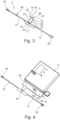
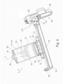
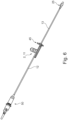
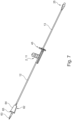
- the pump module 2 is shown individually schematically in Figure 3 shown. A more detailed embodiment of the pump module 2 can be found in Figure 5 again. Also in the characters 6 to 8 the pump module 2 is shown. It has a piston-cylinder unit 11, a first elastically deformable hose section 12 and a second elastically deformable hose section 13.
- the pump module 2 is designed as a disposable item (single-use item, disposable item).
- the hose sections 12, 13 can in particular be designed as a PVC hose.
- the piston-cylinder unit 11 has a cylinder 14, which can consist in particular of plastic and/or can be produced as an injection-molded part, and a piston 15 which can be moved reciprocally therein and which can also in particular be made of plastic and/or can be produced as an injection-molded part.
- the piston 15 is arranged on/on a piston rod 16 and is fixed in position relative to it at least in the axial direction L.
- the cylinder 14 has a bottom wall 17, a peripheral wall 18 and a top wall 19.
- the piston rod 16 projects out of the cylinder 14 in the axial direction L through an opening formed in the cover wall 19.
- the piston 15 is preferably sealed from the peripheral wall 18 by means of seals 20 arranged on both sides, so that the piston-cylinder unit 11 has a fluid space/metering space 21.
- the fluid space 21 is fluidly connected to the first hose section 12 via the inlet bore 22 and fluidly connected to the second hose section 13 via the outlet bore 23.
- the hose sections 12, 13 can in particular be molded onto the cylinder 14. In particular, they can be designed like conventional infusion tubes.
- the first hose section 12 is made of in the embodiment Figure 3 at its end facing away from the piston-cylinder unit 11 is provided with an inlet Luer lock connection 24, which in the present case, as well as in Fig. 8 is designed as a Luer lock inner cone.
- the second hose section 13 is off in the embodiment Figure 3 as well as in the embodiments in the Figures 6 to 9 at its end facing away from the piston-cylinder unit 11 is provided with an outlet Luer lock connection 25, which in the present case is designed as a Luer lock external cone. This means that the pump module 2 can be easily connected to standard infusion units.
- FIG. 2 shows that the pump 1 has a (pump's own) drive 26 for the piston-cylinder unit 11, here in the form of a linear motor 26.
- the motor 26 is arranged congruently to the longitudinal axis L of the piston rod 16 (of the piston-cylinder unit 11), so that forces for reciprocally driving the piston 15 can be transmitted centrally and without twisting/transverse forces.
- the drive 26 is arranged in a fixed position on the lower housing part 4 via mounting in an intermediate wall 27.
- the piston rod 16 can be connected to the drive 26 by means of a coupling element 46 arranged or formed thereon and a counter-element 47 designed to engage therewith.
- the coupling element 47 therefore serves as a holder for the drive/linear motor 26.
- FIG. 2 further shows that the pump 1 has a (pump's own) control unit 28 at least for controlling the squeezing of the hose sections 12, 13.
- the control unit 28 can be technically connected to the first hose section 12 and the second hose section 13 and is arranged on the lower housing part 4 via a further intermediate wall 29.
- It has a rocker arm unit which is motor-driven by means of a (controlled/regulated) drive 30, here a linear motor 30, with a rocker arm 31 and two pressure stamps 32, 33 (valve devices) pivotably arranged thereon.
- the rocker arm 31 is connected to the linear motor 30 via a driver 34 and around it via a rocker bearing 35 Figure 2 pivotally mounted orthogonally to the plane of the drawing and the tilting axis not shown in the figure.
- the pressure stamps 32, 33 are pivotally arranged on a cross arm 38 of the rocker arm 31 by means of pivot bearings 36, 37 and are guided in a linear positioning manner on the lower housing part 4. They are pretensioned by means of compression springs 39, 40 in such a way that the tension of the compression springs 39, 40 pushes them away from the two hose sections 12, 13.
- Figure 2 shows that the pressure stamps 32, 33 are arranged orthogonally to the hose sections 12, 13. They can also be linearly positioned in a direction orthogonal to the hose sections 12, 13.
- the pressure stamps 32, 33 are designed and arranged in such a way and are intended to be in a first tilting position, which is in Figure 2 is shown squeezing the first hose section 12 together and releasing the second hose section 13.
- the pressure stamp 32 on the inlet hose side is from the FIG Figure 2 shown position of the first hose section 12 positioned away, so to speak shifted in the direction of the motor 26, while the pressure stamp 33 on the outlet hose section side is shifted in the direction of the second hose section and squeezes it together.
- the linear motor 30 is in the in Figure 2 situation shown in which the first hose section is squeezed together.
- the rocker arm 31 is stimulated to perform a tilting movement about its bearing 35, which causes the described displacement of the pressure stamps 32, 33.
- the closure flap 6 is between an open position ( Figures 4 and 9 ) and a closed position ( Figures 1 and 2 ) is pivotally arranged on the lower housing part 4. It can be locked to the housing 3 by means of a locking mechanism 41 and for this purpose has locking pins 42 which interact with the mechanism 41. It is furthermore provided with a positioning pin 43, which interacts with the second hose section 13 and ensures that it is positioned as intended on an air sensor 44 when the closure flap 6 is closed.
- the drives 26, 28 of the pump are supplied with energy via a battery 48, which can be charged via a USB port 49.
- a user To use the pump 1, a user first opens the closure flap 6 of the pump 1, for example by inserting a special key into a hole provided on the side and thereby unlocking the flap 6.
- the pump module 2 is equipped with a drip chamber 50 ( Figure 6 ) or equipped with a Spike 51 ( Figures 7 and 9 ), which can also be components of infusion lines designed as disposable items.
- the infusion line including the two hose sections 12, 13, has been filled without air bubbles up to the outlet Luer lock connection 25 / the drip chamber 50 / the spike 51, the first hose section 12 ( Figure 3 ) or the second hose section 13 ( Figures 5 to 9 ) sealed fluid-tight by means of a sliding clamp 45.
- the user then pushes the pump module 2 into the designated receptacle of the pump 1 until the coupling element 46 of the piston rod 16 audibly and/or tactilely engages with the counter element 47 of the drive 26 and the piston-cylinder unit 11 is connected to the drive 26 is.
- the closure flap 6 is then closed.
- the locking mechanism 41 located in the upper housing part 5 ensures that the flap 6 is securely locked.
- the second hose section 13 is placed as intended towards the air sensor, for example pressed against it. This ensures that any air bubbles that may be present or introduced during an infusion are recognized and communicated accordingly.
- the user enters the desired delivery rate via the display elements 8 and the control elements 9. They are displayed via the display 10, which according to one embodiment can be designed as a touch screen, so that input can also be made via the display 10 (operation via an app on the cell phone or tablet is also possible and within the scope of the invention) .
- the pump 1 starts.
- the linear motor 30 moves out of the in Figure 2 position shown and the outlet stamp 33 clamps the second hose section 13 in a fluid-tight manner.
- the inlet stamp 32 opens the first tube cut 12.
- the linear motor 26 for the piston 15 then moves out of the in Figure 2 Position shown backwards and sucks infusion solution through the first hose section 12 into the fluid chamber 21 of the piston-cylinder unit 11.
- the linear motor 30 moves back forward into the in Figure 2 position shown and the inlet stamp 32 closes the first hose section 12 in a fluid-tight manner.
- the outlet stamp 33 opens the second hose section 13.
- the linear motor 26 then moves back into the in as far as it will go Figure 2 position shown forward and presses the infusion liquid located in the fluid chamber 21 into the second hose section 13. This process continues until the specified dosage is reached.
- the closure flap 6 is opened again with the special key.
- the special key can be used to unlock the coupling between drive 26 and Piston rod 16 done. Now the pump module 2 can be removed from the housing 3 of the pump 1.
- An annular bead 52 located in the area of the cover wall 19 (or formed on it) represents an axial stop for a limiting plate 53, which is preferably designed integrally with the piston rod 16. This is the maximum stroke of the piston-cylinder unit 11 through the limiting plate 53 fixed and the piston 15 falling out of the cylinder 14 is prevented in a form-fitting manner.
- the piston 15 On the end side of the piston rod 16 facing the bottom wall 17 of the cylinder 14, the piston 15 is preferably arranged/designed/fixed as a smooth-running piston.
- the piston is further preferably designed as a piston sleeve with a specific sleeve length or as a double piston with two axially spaced piston plates (not shown further).
- seal 20 designed as a movable sealing lip at its distal and proximal ends (or distal and proximal piston plates).
- Figure 5 shows that those seals 20 in a preferred exemplary embodiment are designed as ring seals continuously in the circumferential direction, which ensures negative and positive pressure movement.
- the distance along the longitudinal direction L between the distal and proximal seals 20 of the piston 15 exceeds the piston stroke of the piston-cylinder unit 11. This guarantees that the cylinder wall of the fluid space/dosing space 21 only comes into contact with the one distal seal 20 which ensures its sterility.
- the excess between the distance along the longitudinal direction L between the distal and proximal seals 20 of the piston 15 and the piston stroke is at least 2 mm.
- the pump module 2 also has a handle plate 54.
- This has a T-shape in its cross-sectional profile, which results in a kind of handle bar or handle area 55, by means of which the pump module 2 can be easily grasped and can be inserted into the housing 3 or removed from it.
- the handle bar 55 is arranged at the distal end of the piston-cylinder unit 11 in such a way that the handle bar 55 extends transversely to the cylinder longitudinal axis L, preferably perpendicular thereto and further preferably runs parallel to the hose sections 12, 13.
- the handle bar/plate 54 is provided at its end facing/located on the side of the first hose section 12 with a sleeve or eyelet 56 which projects transversely to the handle bar/plate and whose longitudinal axis runs parallel to the handle bar/plate.
- the sleeve/eyelet 56 is preferably designed integrally with the handle strip/plate 54 and serves to fix an infusion line (eg the tube section 12) which is passed through it. It thus defines a circular hollow section in which the infusion line rests/is inserted after its insertion.
- the handle strip/plate 54 is mechanically coupled to the sliding clamp 45.
- locking cams or spring tongues with locking projections 57 are attached/formed on the handle strip/plate 54, whereas an insertion shaft is formed on the sliding clamp 45.
- the locking cams 57 are, for example, cuboid or spherical protruding elements which engage in corresponding counter eyelets/recesses/recesses in the insertion shaft or its peripheral wall of the sliding clamp 45 in order to couple them with the handle strip/plate 54 in a defined position.
- This connection is therefore a positive connection, which is realized by snapping the counter eyelets over the locking cams 57.
- the sliding clamp 45 has a rigid part or frame 58 and a movable part or slider 59 which is mounted in the rigid part or frame 58.
- the slider 59 as well as the frame 58 are each formed with a through hole/opening, which are positioned congruently in a first sliding position and are displaced relative to one another in a second sliding position. In the second sliding position/state in which the pump 1 is not delivering or the pump module 2 is not inserted into the housing 3, these clamp the first hose section 13 in such a way that its freedom from air bubbles is guaranteed.
- the movable part 59 is moved relative to the rigid part 58 such that the one, first opening 60, which is formed by the rigid part 58, and the other, second opening 61, which is formed by the movable part 59 of the sliding clamp 45 is formed, are flush with one another (overlapping each other) and thus release a fluid flow through the second hose section 13, which is passed through the two through holes/openings.
- the infusion pump 1 can be used for all applications of an infusion, that is to say those with a high delivery volume and those with high accuracy requirements, is further enhanced by the fact that all infusion sets can be connected to the pump.
- Revealed as an example of this Figure 6 the coupling of the first hose section 12 with a drip chamber 50. It is thus possible to couple the pump module 2 with a drip chamber 50 and then insert this unit into the housing 3.
- the drip chamber 50 which is usually part of every infusion system, can thus be arranged directly downstream of the pump module 2, whereby the compactness of the entire infusion system is optionally increased. It serves to regulate the formation of drips of the administered liquid and to prevent the formation of air bubbles.
- FIG. 7 Another embodiment is shown with a different infusion set.
- the infusion line here has a spike 62 downstream of the pump module 2. This represents the connector that creates a reliable connection between an external infusion container and the infusion lines.
- the spike 62 can be divided into a piercing mandrel 63 and a holding seat 64. A spike stop 65 is formed between these, which enables the spike 62 to sit securely.
- Figure 8 is the first hose section 12, as in Figure 3 , provided with the inlet Luer lock connection / Luer lock inner cone 24.
- the sliding clamp 45 is in such a state that it allows flow through the second hose section 13.
- the pump module 2 is inserted into the housing 3, as in Figure 2 and in Figure 9 shown.
- Figure 9 shows the embodiment in which the spike 62 is connected to the first hose section 12.
Landscapes
- Health & Medical Sciences (AREA)
- Engineering & Computer Science (AREA)
- Heart & Thoracic Surgery (AREA)
- Animal Behavior & Ethology (AREA)
- Public Health (AREA)
- Biomedical Technology (AREA)
- Hematology (AREA)
- Life Sciences & Earth Sciences (AREA)
- Veterinary Medicine (AREA)
- General Health & Medical Sciences (AREA)
- Anesthesiology (AREA)
- Vascular Medicine (AREA)
- Mechanical Engineering (AREA)
- General Engineering & Computer Science (AREA)
- Pulmonology (AREA)
- Computer Hardware Design (AREA)
- Infusion, Injection, And Reservoir Apparatuses (AREA)
Claims (11)
- Module de pompe (2) destiné à une pompe à perfusion médico-technique (1) pour amener un liquide provenant d'une source de liquide à un patient, ledit module de pompe (2) présente :une unité piston-cylindre (11), en particulier une unité piston-cylindre (11) distincte, qui est adaptée pour pouvoir être mis en prise active avec un mécanisme d'entraînement (26) de la pompe à perfusion (1), pour être actionnée par celui-ci et pour être raccordée à une première section de tuyau (12) pour l'apport de liquide et à une seconde section de tuyau (13) pour l'apport de liquide,une pince coulissante (45), qui peut coulisser de telle manière qu'elle libère ou bloque sélectivement un écoulement de liquide dans la première et/ou la seconde section de tuyau (12, 13)caractérisé parune plaque de préhension (54) au niveau de l'extrémité distale de l'unité piston-cylindre (11), etun manchon (56) sur la plaque de préhension (54), qui est disposé sur l'une des extrémités du module de pompe (2) opposées à la pince coulissante (45) et est préparé pour fixer la première et/ou la seconde section de tuyau (12, 13), selon lequel la pince coulissante peut être enclipsée sur une zone de préhension (55) de la plaque de préhension (54).
- Module de pompe (2) selon la revendication 1, caractérisé en ce que l'unité piston-cylindre (11) présente un cylindre (14) et un piston (15) pouvant se déplacer réciproquement dans celle-ci et un élément de couplage (46) pour le couplage amovible avec un contre-élément (47) correspondant d'un entraînement, en particulier du mécanisme d'entraînement de la pompe à perfusion (1).
- Module de pompe (2) selon la revendication 2, caractérisé en ce que l'élément de couplage (46) est conçu sous la forme d'un raccord enfichable et peut être couplé automatiquement ou obligatoirement avec le mécanisme d'entraînement/l'entraînement (26) lors de l'agencement conforme à sa destination du module de pompe (2) dans la pompe à perfusion (1).
- Module de pompe (2) selon la revendication 2 ou 3, caractérisé en ce que l'élément de couplage (46) présente des structures d'encliquetage, qui maintiennent ensemble l'élément de couplage (46) et le contre-élément (47) et en particulier permettent un encliquetage audible et/ou tactile pour un utilisateur de l'élément de couplage (46) et du contre-élément (47).
- Module de pompe (2) selon l'une quelconque des revendications 2 à 4, caractérisé en ce que le piston (15) est pourvu de joints d'étanchéité (20) des deux côtés dans la direction axiale (L) et est rendu étanche par rapport au cylindre (14), en particulier au moyen d'un joint d'étanchéité (20) proximal et d'un joint d'étanchéité (20) distal, selon lequel le joint d'étanchéité (20) proximal et le joint d'étanchéité (20) distal s'étendent l'un par rapport à l'autre parallèlement au plan.
- Module de pompe (2) selon l'une quelconque des revendications 2 à 5, caractérisé en ce que le piston (15) est plus long que le niveau de remplissage maximal du cylindre (14), en particulier selon lequel la distance entre le joint d'étanchéité (20) proximal et le joint d'étanchéité (20) distal est réalisée de manière plus grande que la course de refoulement de l'unité piston-cylindre (11).
- Module de pompe (2) selon l'une quelconque des revendications 2 à 5, caractérisé en ce que le module de pompe (2) présente la plaque de préhension (54)/la section de préhension (54), qui présente en section transversale une forme en T, selon lequel il en résulte la poignée (55) ou la zone de préhension (55), au moyen de laquelle le module de pompe (2) peut être saisi facilement et peut être inséré dans un boîtier (3) de la pompe à perfusion (1) ou peut en être retiré.
- Module de pompe (2) selon la revendication 7, caractérisé en ce que la poignée (55) ou la zone de préhension (55) est disposée au niveau de l'extrémité distale de l'unité piston-cylindre (11) de telle manière que la poignée (55) ou la zone de préhension (55) s'étend transversalement à l'axe longitudinale du cylindre L, de préférence perpendiculairement à celui, ainsi que plus préférentiellement s'étend parallèlement aux sections de tuyau (12, 13).
- Module de pompe (2) selon la revendication 7 ou 8, caractérisé en ce que la plaque de préhension (54) ou la section de préhension (54) est pourvue au niveau de son extrémité tournée/se trouvant sur le côté de la première section de tuyau (12), du manchon (56) qui fait saillie transversalement par rapport à la plaque de préhension (54) ou par rapport à la section de préhension (54) et dont l'axe longitudinal s'étend parallèlement à la plaque de préhension (54) ou à la section de préhension (54).
- Module de pompe (2) selon l'une quelconque des revendications 7 à 9, caractérisé en ce que des ergots d'encliquetage ou des languettes élastiques avec des saillies d'encliquetage (57) sont monté(e)s/conçu(e)s au niveau de la plaque de préhension (54) ou la section de préhension (54), tandis qu'une fente d'insertion est formée au niveau de la pince coulissante (45), par exemple des éléments en saillie parallélépipédiques ou sphériques, qui entrent en prise dans des évidements correspondants dans la fente d'insertion ou sa paroi périphérique de la pince coulissante (45), pour coupler celles-ci définies selon une position à la plaque de préhension (54) ou à la section de préhension (54).
- Module de pompe (2) selon l'une quelconque des revendications 7 à 10, caractérisé en ce que la pince coulissante (45) présente une partie ou un cadre (58) rigide et une partie ou coulisseau (59) mobile, qui est logé dans la partie ou cadre (58) rigide, selon lequel le coulisseau (59), ainsi que le cadre (58) sont formés respectivement avec un trou traversant/ouverture (60, 61), qui sont positionnés dans une première position coulissante de manière à coïncider et sont décalés l'un par rapport à l'autre dans une seconde position coulissante.
Applications Claiming Priority (2)
| Application Number | Priority Date | Filing Date | Title |
|---|---|---|---|
| DE102017111299.5A DE102017111299A1 (de) | 2017-05-23 | 2017-05-23 | Infusionspumpe mit einem verschiedene Betriebszustände einnehmbaren Pumpmodul |
| PCT/EP2018/063511 WO2018215544A1 (fr) | 2017-05-23 | 2018-05-23 | Module de pompe pour une pompe à perfusion technique médicale pourvu de différents états de fonctionnement |
Publications (2)
| Publication Number | Publication Date |
|---|---|
| EP3630264A1 EP3630264A1 (fr) | 2020-04-08 |
| EP3630264B1 true EP3630264B1 (fr) | 2023-12-13 |
Family
ID=62235968
Family Applications (3)
| Application Number | Title | Priority Date | Filing Date |
|---|---|---|---|
| EP18726799.2A Active EP3630264B1 (fr) | 2017-05-23 | 2018-05-23 | Module de pompe pour une pompe à perfusion technique médicale pourvu de différents états de fonctionnement |
| EP18726983.2A Active EP3630225B1 (fr) | 2017-05-23 | 2018-05-23 | Pompe à perfusion comportant un module de pompe pouvant adopter divers états de fonctionnement |
| EP18726798.4A Active EP3630224B1 (fr) | 2017-05-23 | 2018-05-23 | Module de pompe stérile pour une pompe a perfusion |
Family Applications After (2)
| Application Number | Title | Priority Date | Filing Date |
|---|---|---|---|
| EP18726983.2A Active EP3630225B1 (fr) | 2017-05-23 | 2018-05-23 | Pompe à perfusion comportant un module de pompe pouvant adopter divers états de fonctionnement |
| EP18726798.4A Active EP3630224B1 (fr) | 2017-05-23 | 2018-05-23 | Module de pompe stérile pour une pompe a perfusion |
Country Status (8)
| Country | Link |
|---|---|
| US (1) | US11395876B2 (fr) |
| EP (3) | EP3630264B1 (fr) |
| JP (1) | JP7138121B2 (fr) |
| CN (1) | CN110869073B (fr) |
| DE (1) | DE102017111299A1 (fr) |
| PL (1) | PL3630225T3 (fr) |
| RU (1) | RU2019142689A (fr) |
| WO (3) | WO2018215542A1 (fr) |
Families Citing this family (4)
| Publication number | Priority date | Publication date | Assignee | Title |
|---|---|---|---|---|
| ATE480278T1 (de) | 2005-09-12 | 2010-09-15 | Unomedical As | Einfürungssystem für ein infusionsset mit einem ersten und zweiten federeinheit |
| US10194938B2 (en) | 2011-03-14 | 2019-02-05 | UnoMedical, AS | Inserter system with transport protection |
| CA3141608A1 (fr) | 2019-05-20 | 2020-11-26 | Unomedical A/S | Dispositif de perfusion rotative et methodes associees |
| EP4424343A1 (fr) | 2023-03-03 | 2024-09-04 | B. Braun Melsungen AG | Pompe à perfusion dotée d'une unité de commande |
Family Cites Families (27)
| Publication number | Priority date | Publication date | Assignee | Title |
|---|---|---|---|---|
| US3901231A (en) | 1974-02-07 | 1975-08-26 | Baxter Laboratories Inc | Infusion pump apparatus |
| US3985133A (en) | 1974-05-28 | 1976-10-12 | Imed Corporation | IV pump |
| US4396385A (en) | 1980-12-05 | 1983-08-02 | Baxter Travenol Laboratories, Inc. | Flow metering apparatus for a fluid infusion system |
| JPS5985665A (ja) * | 1982-09-13 | 1984-05-17 | イメツド・コ−ポレ−シヨン | 患者への流体供給装置および方法 |
| US4515591A (en) * | 1982-09-28 | 1985-05-07 | Ivac Corporation | Disposable syringe cartridge for fluid delivery apparatus |
| US4519792A (en) * | 1982-12-06 | 1985-05-28 | Abbott Laboratories | Infusion pump system |
| US4689043A (en) * | 1986-03-19 | 1987-08-25 | Imed Corporation | IV tube activator |
| RU2019191C1 (ru) | 1991-11-06 | 1994-09-15 | Производственное объединение "Вологодский оптико-механический завод" | Инфузионный насос-дозатор |
| US5976112A (en) | 1997-11-07 | 1999-11-02 | Lyza Weiss Jennings & Shea | Injector syringe |
| US6629955B2 (en) * | 2001-05-04 | 2003-10-07 | Alaris Medical Systems, Inc. | Medical instrument flow stop interface |
| US6796957B2 (en) | 2001-07-10 | 2004-09-28 | Myocardial Therapeutics, Inc. | Sterile aspiration/reinjection systems |
| JP2003199827A (ja) | 2001-12-28 | 2003-07-15 | Terumo Corp | シリンジ |
| DE20200885U1 (de) | 2002-01-22 | 2003-05-28 | B. Braun Melsungen Ag, 34212 Melsungen | Spritzenpumpe mit Kolbenbremse |
| JP4594147B2 (ja) | 2005-03-29 | 2010-12-08 | テルモ株式会社 | シリンジ用外筒、シリンジ、シリンジ用外筒の射出成形用金型およびシリンジ用外筒の製造方法 |
| WO2008133702A1 (fr) | 2007-04-30 | 2008-11-06 | Medtronic Minimed, Inc. | Introduction d'aiguille et raccord d'écoulement de fluide pour un système d'administration de milieu d'infusion |
| EP2373374B1 (fr) | 2008-10-22 | 2020-05-13 | Sterling Investments LC | Dispositif de pompe miniature équipé d'une vanne anti-écoulement libre |
| US20140194778A1 (en) | 2009-06-03 | 2014-07-10 | Biometrix Ltd. | Syringe enabled for aspirating blood into a sampling site in a closed manner and method |
| WO2011044294A1 (fr) | 2009-10-06 | 2011-04-14 | Flex Partners, Inc. | Systèmes d'administration de fluide de précision |
| KR100985446B1 (ko) | 2009-12-04 | 2010-10-05 | 송경진 | 가역성 1회용 혈관 수지침 |
| US8337175B2 (en) | 2009-12-22 | 2012-12-25 | Smith & Nephew, Inc. | Disposable pumping system and coupler |
| CN103946544B (zh) | 2011-09-15 | 2017-06-06 | 牛津纳米孔技术有限公司 | 泵 |
| EP2780054A1 (fr) | 2011-11-18 | 2014-09-24 | Sanofi-Aventis Deutschland GmbH | Agencement de moteur d'entraînement à piston |
| DE102012102272A1 (de) * | 2012-03-19 | 2013-09-19 | B. Braun Melsungen Ag | Kolbenpumpe; Vorrichtung zur Zuführung und Dosierung eines Fluids für medizinische Zwecke mittels Kolbenpumpe |
| EP2902052B1 (fr) | 2012-09-26 | 2017-08-16 | Terumo Kabushiki Kaisha | Dispositif d'administration de fluide médical |
| US9511186B1 (en) * | 2012-10-23 | 2016-12-06 | Acist Medical Systems, Inc. | Medical injection systems and pumps |
| KR20160088852A (ko) * | 2013-07-16 | 2016-07-26 | 유니트랙트 시린지 피티와이 엘티디 | 주사 가능 물질의 반복적 혼합 및 주입용 주사기 |
| DE102014224819A1 (de) | 2014-12-03 | 2016-06-09 | B. Braun Melsungen Ag | Medizinische Pumpvorrichtung und Schlauchleitung hierfür |
-
2017
- 2017-05-23 DE DE102017111299.5A patent/DE102017111299A1/de not_active Withdrawn
-
2018
- 2018-05-23 WO PCT/EP2018/063509 patent/WO2018215542A1/fr not_active Ceased
- 2018-05-23 WO PCT/EP2018/063510 patent/WO2018215543A1/fr not_active Ceased
- 2018-05-23 EP EP18726799.2A patent/EP3630264B1/fr active Active
- 2018-05-23 CN CN201880044269.6A patent/CN110869073B/zh active Active
- 2018-05-23 EP EP18726983.2A patent/EP3630225B1/fr active Active
- 2018-05-23 WO PCT/EP2018/063511 patent/WO2018215544A1/fr not_active Ceased
- 2018-05-23 EP EP18726798.4A patent/EP3630224B1/fr active Active
- 2018-05-23 JP JP2019564846A patent/JP7138121B2/ja active Active
- 2018-05-23 RU RU2019142689A patent/RU2019142689A/ru unknown
- 2018-05-23 PL PL18726983.2T patent/PL3630225T3/pl unknown
- 2018-05-23 US US16/616,018 patent/US11395876B2/en active Active
Also Published As
| Publication number | Publication date |
|---|---|
| CN110869073A (zh) | 2020-03-06 |
| JP2020520747A (ja) | 2020-07-16 |
| JP7138121B2 (ja) | 2022-09-15 |
| WO2018215542A1 (fr) | 2018-11-29 |
| EP3630264A1 (fr) | 2020-04-08 |
| US20200086041A1 (en) | 2020-03-19 |
| EP3630224A1 (fr) | 2020-04-08 |
| EP3630224B1 (fr) | 2023-05-03 |
| WO2018215543A1 (fr) | 2018-11-29 |
| WO2018215544A1 (fr) | 2018-11-29 |
| PL3630225T3 (pl) | 2024-08-19 |
| CN110869073B (zh) | 2022-03-18 |
| US11395876B2 (en) | 2022-07-26 |
| RU2019142689A3 (fr) | 2021-09-10 |
| EP3630225A1 (fr) | 2020-04-08 |
| DE102017111299A1 (de) | 2018-11-29 |
| RU2019142689A (ru) | 2021-06-23 |
| EP3630225B1 (fr) | 2024-04-24 |
Similar Documents
| Publication | Publication Date | Title |
|---|---|---|
| EP3050585B1 (fr) | Appareil de dosage destiné à la distribution d'un fluide dans des conditions aseptiques | |
| EP3630264B1 (fr) | Module de pompe pour une pompe à perfusion technique médicale pourvu de différents états de fonctionnement | |
| EP1970677B1 (fr) | Système d'infusion avec dispositif de dosage | |
| DE69328271T2 (de) | Flüssigkeitssteuervorrichtung mit automatischen Ventil | |
| DE3876143T2 (de) | Wegwerfbare infusionskassette mit pumpenkammer sowie triebwerk dafuer. | |
| EP0389477B1 (fr) | Dispositif d'injection utilise avec une ampoule deformable | |
| DE69617403T2 (de) | Pumpenkammer und ventil für eine pumpenkammer | |
| EP2039382B1 (fr) | Ampoule dotée d'un joint en deux états de compression | |
| EP3468642A2 (fr) | Appareil de dosage et dispositif d'injection | |
| DE2652197A1 (de) | Druckpumpe fuer eine infusionsvorrichtung | |
| EP1448252A1 (fr) | Ensemble pompe medicale | |
| EP3610899B1 (fr) | Dispositif d'aspiration et d'alimentation comprenant une unité d'entraînement et partie de raccordement | |
| WO2020025484A1 (fr) | Système de perfusion comprenant une pompe de perfusion et un module de pompage pouvant être accouplé à celle-ci | |
| EP2023976A1 (fr) | Dispositif destiné à l'administration d'un produit fluide | |
| EP2535071B1 (fr) | Dispositif de médication pour la distribuer dosée d'un fluide | |
| DE202022100988U1 (de) | Dosiergerät für medizinische Lösungen | |
| EP2679255B1 (fr) | Système de pompe, pompe tubulaire et cassette tubulaire ainsi que procédé de configuration d'un système de pompe | |
| DE19614337A1 (de) | Medikamenten-Applikationsvorrichtung | |
| CH705428A2 (de) | Vorrichtung zur Verabreichung eines fluiden Produktes. | |
| EP3600470A1 (fr) | Dispositif présentant une unité de pompe péristaltique pouvant être accouplée | |
| DE29818577U1 (de) | Medizinisches Flüssigkeitsübertragungssystem | |
| DE3515823A1 (de) | Implantierbares medikamentendosiergeraet mit schaltbarem ventil | |
| EP0489297A1 (fr) | Système d'infusion avec un dispositif de détournement du volume d'un bolus | |
| DE9005193U1 (de) | Vorrichtung zum kontinuierlichen Auspressen von gasförmigen, flüssigen oder pastösen Medien aus handelsüblichen Vorratsbehältern |
Legal Events
| Date | Code | Title | Description |
|---|---|---|---|
| STAA | Information on the status of an ep patent application or granted ep patent |
Free format text: STATUS: UNKNOWN |
|
| STAA | Information on the status of an ep patent application or granted ep patent |
Free format text: STATUS: THE INTERNATIONAL PUBLICATION HAS BEEN MADE |
|
| PUAI | Public reference made under article 153(3) epc to a published international application that has entered the european phase |
Free format text: ORIGINAL CODE: 0009012 |
|
| STAA | Information on the status of an ep patent application or granted ep patent |
Free format text: STATUS: REQUEST FOR EXAMINATION WAS MADE |
|
| 17P | Request for examination filed |
Effective date: 20191220 |
|
| AK | Designated contracting states |
Kind code of ref document: A1 Designated state(s): AL AT BE BG CH CY CZ DE DK EE ES FI FR GB GR HR HU IE IS IT LI LT LU LV MC MK MT NL NO PL PT RO RS SE SI SK SM TR |
|
| AX | Request for extension of the european patent |
Extension state: BA ME |
|
| DAV | Request for validation of the european patent (deleted) | ||
| DAX | Request for extension of the european patent (deleted) | ||
| STAA | Information on the status of an ep patent application or granted ep patent |
Free format text: STATUS: EXAMINATION IS IN PROGRESS |
|
| 17Q | First examination report despatched |
Effective date: 20221209 |
|
| GRAP | Despatch of communication of intention to grant a patent |
Free format text: ORIGINAL CODE: EPIDOSNIGR1 |
|
| STAA | Information on the status of an ep patent application or granted ep patent |
Free format text: STATUS: GRANT OF PATENT IS INTENDED |
|
| INTG | Intention to grant announced |
Effective date: 20230703 |
|
| RIN1 | Information on inventor provided before grant (corrected) |
Inventor name: STEGER, JUERGEN Inventor name: HARTUNG, JUERGEN Inventor name: FUCHS, JUERGEN |
|
| P01 | Opt-out of the competence of the unified patent court (upc) registered |
Effective date: 20230901 |
|
| GRAS | Grant fee paid |
Free format text: ORIGINAL CODE: EPIDOSNIGR3 |
|
| GRAA | (expected) grant |
Free format text: ORIGINAL CODE: 0009210 |
|
| STAA | Information on the status of an ep patent application or granted ep patent |
Free format text: STATUS: THE PATENT HAS BEEN GRANTED |
|
| AK | Designated contracting states |
Kind code of ref document: B1 Designated state(s): AL AT BE BG CH CY CZ DE DK EE ES FI FR GB GR HR HU IE IS IT LI LT LU LV MC MK MT NL NO PL PT RO RS SE SI SK SM TR |
|
| REG | Reference to a national code |
Ref country code: GB Ref legal event code: FG4D Free format text: NOT ENGLISH |
|
| REG | Reference to a national code |
Ref country code: CH Ref legal event code: EP |
|
| REG | Reference to a national code |
Ref country code: DE Ref legal event code: R096 Ref document number: 502018013801 Country of ref document: DE |
|
| REG | Reference to a national code |
Ref country code: IE Ref legal event code: FG4D Free format text: LANGUAGE OF EP DOCUMENT: GERMAN |
|
| PG25 | Lapsed in a contracting state [announced via postgrant information from national office to epo] |
Ref country code: GR Free format text: LAPSE BECAUSE OF FAILURE TO SUBMIT A TRANSLATION OF THE DESCRIPTION OR TO PAY THE FEE WITHIN THE PRESCRIBED TIME-LIMIT Effective date: 20240314 |
|
| REG | Reference to a national code |
Ref country code: LT Ref legal event code: MG9D |
|
| PG25 | Lapsed in a contracting state [announced via postgrant information from national office to epo] |
Ref country code: LT Free format text: LAPSE BECAUSE OF FAILURE TO SUBMIT A TRANSLATION OF THE DESCRIPTION OR TO PAY THE FEE WITHIN THE PRESCRIBED TIME-LIMIT Effective date: 20231213 |
|
| REG | Reference to a national code |
Ref country code: NL Ref legal event code: MP Effective date: 20231213 |
|
| PG25 | Lapsed in a contracting state [announced via postgrant information from national office to epo] |
Ref country code: ES Free format text: LAPSE BECAUSE OF FAILURE TO SUBMIT A TRANSLATION OF THE DESCRIPTION OR TO PAY THE FEE WITHIN THE PRESCRIBED TIME-LIMIT Effective date: 20231213 |
|
| PG25 | Lapsed in a contracting state [announced via postgrant information from national office to epo] |
Ref country code: LT Free format text: LAPSE BECAUSE OF FAILURE TO SUBMIT A TRANSLATION OF THE DESCRIPTION OR TO PAY THE FEE WITHIN THE PRESCRIBED TIME-LIMIT Effective date: 20231213 Ref country code: GR Free format text: LAPSE BECAUSE OF FAILURE TO SUBMIT A TRANSLATION OF THE DESCRIPTION OR TO PAY THE FEE WITHIN THE PRESCRIBED TIME-LIMIT Effective date: 20240314 Ref country code: ES Free format text: LAPSE BECAUSE OF FAILURE TO SUBMIT A TRANSLATION OF THE DESCRIPTION OR TO PAY THE FEE WITHIN THE PRESCRIBED TIME-LIMIT Effective date: 20231213 Ref country code: BG Free format text: LAPSE BECAUSE OF FAILURE TO SUBMIT A TRANSLATION OF THE DESCRIPTION OR TO PAY THE FEE WITHIN THE PRESCRIBED TIME-LIMIT Effective date: 20240313 |
|
| PG25 | Lapsed in a contracting state [announced via postgrant information from national office to epo] |
Ref country code: NL Free format text: LAPSE BECAUSE OF FAILURE TO SUBMIT A TRANSLATION OF THE DESCRIPTION OR TO PAY THE FEE WITHIN THE PRESCRIBED TIME-LIMIT Effective date: 20231213 |
|
| PG25 | Lapsed in a contracting state [announced via postgrant information from national office to epo] |
Ref country code: SE Free format text: LAPSE BECAUSE OF FAILURE TO SUBMIT A TRANSLATION OF THE DESCRIPTION OR TO PAY THE FEE WITHIN THE PRESCRIBED TIME-LIMIT Effective date: 20231213 Ref country code: RS Free format text: LAPSE BECAUSE OF FAILURE TO SUBMIT A TRANSLATION OF THE DESCRIPTION OR TO PAY THE FEE WITHIN THE PRESCRIBED TIME-LIMIT Effective date: 20231213 Ref country code: NO Free format text: LAPSE BECAUSE OF FAILURE TO SUBMIT A TRANSLATION OF THE DESCRIPTION OR TO PAY THE FEE WITHIN THE PRESCRIBED TIME-LIMIT Effective date: 20240313 Ref country code: NL Free format text: LAPSE BECAUSE OF FAILURE TO SUBMIT A TRANSLATION OF THE DESCRIPTION OR TO PAY THE FEE WITHIN THE PRESCRIBED TIME-LIMIT Effective date: 20231213 Ref country code: LV Free format text: LAPSE BECAUSE OF FAILURE TO SUBMIT A TRANSLATION OF THE DESCRIPTION OR TO PAY THE FEE WITHIN THE PRESCRIBED TIME-LIMIT Effective date: 20231213 Ref country code: HR Free format text: LAPSE BECAUSE OF FAILURE TO SUBMIT A TRANSLATION OF THE DESCRIPTION OR TO PAY THE FEE WITHIN THE PRESCRIBED TIME-LIMIT Effective date: 20231213 |
|
| PG25 | Lapsed in a contracting state [announced via postgrant information from national office to epo] |
Ref country code: IS Free format text: LAPSE BECAUSE OF FAILURE TO SUBMIT A TRANSLATION OF THE DESCRIPTION OR TO PAY THE FEE WITHIN THE PRESCRIBED TIME-LIMIT Effective date: 20240413 |
|
| PG25 | Lapsed in a contracting state [announced via postgrant information from national office to epo] |
Ref country code: CZ Free format text: LAPSE BECAUSE OF FAILURE TO SUBMIT A TRANSLATION OF THE DESCRIPTION OR TO PAY THE FEE WITHIN THE PRESCRIBED TIME-LIMIT Effective date: 20231213 |
|
| PG25 | Lapsed in a contracting state [announced via postgrant information from national office to epo] |
Ref country code: SK Free format text: LAPSE BECAUSE OF FAILURE TO SUBMIT A TRANSLATION OF THE DESCRIPTION OR TO PAY THE FEE WITHIN THE PRESCRIBED TIME-LIMIT Effective date: 20231213 |
|
| PG25 | Lapsed in a contracting state [announced via postgrant information from national office to epo] |
Ref country code: SM Free format text: LAPSE BECAUSE OF FAILURE TO SUBMIT A TRANSLATION OF THE DESCRIPTION OR TO PAY THE FEE WITHIN THE PRESCRIBED TIME-LIMIT Effective date: 20231213 Ref country code: SK Free format text: LAPSE BECAUSE OF FAILURE TO SUBMIT A TRANSLATION OF THE DESCRIPTION OR TO PAY THE FEE WITHIN THE PRESCRIBED TIME-LIMIT Effective date: 20231213 Ref country code: RO Free format text: LAPSE BECAUSE OF FAILURE TO SUBMIT A TRANSLATION OF THE DESCRIPTION OR TO PAY THE FEE WITHIN THE PRESCRIBED TIME-LIMIT Effective date: 20231213 Ref country code: IT Free format text: LAPSE BECAUSE OF FAILURE TO SUBMIT A TRANSLATION OF THE DESCRIPTION OR TO PAY THE FEE WITHIN THE PRESCRIBED TIME-LIMIT Effective date: 20231213 Ref country code: IS Free format text: LAPSE BECAUSE OF FAILURE TO SUBMIT A TRANSLATION OF THE DESCRIPTION OR TO PAY THE FEE WITHIN THE PRESCRIBED TIME-LIMIT Effective date: 20240413 Ref country code: EE Free format text: LAPSE BECAUSE OF FAILURE TO SUBMIT A TRANSLATION OF THE DESCRIPTION OR TO PAY THE FEE WITHIN THE PRESCRIBED TIME-LIMIT Effective date: 20231213 Ref country code: CZ Free format text: LAPSE BECAUSE OF FAILURE TO SUBMIT A TRANSLATION OF THE DESCRIPTION OR TO PAY THE FEE WITHIN THE PRESCRIBED TIME-LIMIT Effective date: 20231213 |
|
| PG25 | Lapsed in a contracting state [announced via postgrant information from national office to epo] |
Ref country code: PL Free format text: LAPSE BECAUSE OF FAILURE TO SUBMIT A TRANSLATION OF THE DESCRIPTION OR TO PAY THE FEE WITHIN THE PRESCRIBED TIME-LIMIT Effective date: 20231213 Ref country code: PT Free format text: LAPSE BECAUSE OF FAILURE TO SUBMIT A TRANSLATION OF THE DESCRIPTION OR TO PAY THE FEE WITHIN THE PRESCRIBED TIME-LIMIT Effective date: 20240415 |
|
| PG25 | Lapsed in a contracting state [announced via postgrant information from national office to epo] |
Ref country code: PT Free format text: LAPSE BECAUSE OF FAILURE TO SUBMIT A TRANSLATION OF THE DESCRIPTION OR TO PAY THE FEE WITHIN THE PRESCRIBED TIME-LIMIT Effective date: 20240415 Ref country code: PL Free format text: LAPSE BECAUSE OF FAILURE TO SUBMIT A TRANSLATION OF THE DESCRIPTION OR TO PAY THE FEE WITHIN THE PRESCRIBED TIME-LIMIT Effective date: 20231213 |
|
| REG | Reference to a national code |
Ref country code: DE Ref legal event code: R097 Ref document number: 502018013801 Country of ref document: DE |
|
| PG25 | Lapsed in a contracting state [announced via postgrant information from national office to epo] |
Ref country code: DK Free format text: LAPSE BECAUSE OF FAILURE TO SUBMIT A TRANSLATION OF THE DESCRIPTION OR TO PAY THE FEE WITHIN THE PRESCRIBED TIME-LIMIT Effective date: 20231213 |
|
| PLBE | No opposition filed within time limit |
Free format text: ORIGINAL CODE: 0009261 |
|
| STAA | Information on the status of an ep patent application or granted ep patent |
Free format text: STATUS: NO OPPOSITION FILED WITHIN TIME LIMIT |
|
| PG25 | Lapsed in a contracting state [announced via postgrant information from national office to epo] |
Ref country code: SI Free format text: LAPSE BECAUSE OF FAILURE TO SUBMIT A TRANSLATION OF THE DESCRIPTION OR TO PAY THE FEE WITHIN THE PRESCRIBED TIME-LIMIT Effective date: 20231213 |
|
| PG25 | Lapsed in a contracting state [announced via postgrant information from national office to epo] |
Ref country code: SI Free format text: LAPSE BECAUSE OF FAILURE TO SUBMIT A TRANSLATION OF THE DESCRIPTION OR TO PAY THE FEE WITHIN THE PRESCRIBED TIME-LIMIT Effective date: 20231213 Ref country code: DK Free format text: LAPSE BECAUSE OF FAILURE TO SUBMIT A TRANSLATION OF THE DESCRIPTION OR TO PAY THE FEE WITHIN THE PRESCRIBED TIME-LIMIT Effective date: 20231213 |
|
| 26N | No opposition filed |
Effective date: 20240916 |
|
| REG | Reference to a national code |
Ref country code: CH Ref legal event code: PL |
|
| PG25 | Lapsed in a contracting state [announced via postgrant information from national office to epo] |
Ref country code: MC Free format text: LAPSE BECAUSE OF FAILURE TO SUBMIT A TRANSLATION OF THE DESCRIPTION OR TO PAY THE FEE WITHIN THE PRESCRIBED TIME-LIMIT Effective date: 20231213 |
|
| PG25 | Lapsed in a contracting state [announced via postgrant information from national office to epo] |
Ref country code: LU Free format text: LAPSE BECAUSE OF NON-PAYMENT OF DUE FEES Effective date: 20240523 |
|
| GBPC | Gb: european patent ceased through non-payment of renewal fee |
Effective date: 20240523 |
|
| PG25 | Lapsed in a contracting state [announced via postgrant information from national office to epo] |
Ref country code: MC Free format text: LAPSE BECAUSE OF FAILURE TO SUBMIT A TRANSLATION OF THE DESCRIPTION OR TO PAY THE FEE WITHIN THE PRESCRIBED TIME-LIMIT Effective date: 20231213 Ref country code: LU Free format text: LAPSE BECAUSE OF NON-PAYMENT OF DUE FEES Effective date: 20240523 Ref country code: CH Free format text: LAPSE BECAUSE OF NON-PAYMENT OF DUE FEES Effective date: 20240531 |
|
| REG | Reference to a national code |
Ref country code: BE Ref legal event code: MM Effective date: 20240531 |
|
| PG25 | Lapsed in a contracting state [announced via postgrant information from national office to epo] |
Ref country code: IE Free format text: LAPSE BECAUSE OF NON-PAYMENT OF DUE FEES Effective date: 20240523 |
|
| PG25 | Lapsed in a contracting state [announced via postgrant information from national office to epo] |
Ref country code: BE Free format text: LAPSE BECAUSE OF NON-PAYMENT OF DUE FEES Effective date: 20240531 |
|
| PG25 | Lapsed in a contracting state [announced via postgrant information from national office to epo] |
Ref country code: GB Free format text: LAPSE BECAUSE OF NON-PAYMENT OF DUE FEES Effective date: 20240523 |
|
| PGFP | Annual fee paid to national office [announced via postgrant information from national office to epo] |
Ref country code: DE Payment date: 20250519 Year of fee payment: 8 |
|
| REG | Reference to a national code |
Ref country code: AT Ref legal event code: MM01 Ref document number: 1639968 Country of ref document: AT Kind code of ref document: T Effective date: 20240523 |
|
| PGFP | Annual fee paid to national office [announced via postgrant information from national office to epo] |
Ref country code: FR Payment date: 20250521 Year of fee payment: 8 |
|
| PG25 | Lapsed in a contracting state [announced via postgrant information from national office to epo] |
Ref country code: AT Free format text: LAPSE BECAUSE OF NON-PAYMENT OF DUE FEES Effective date: 20240523 |
|
| PG25 | Lapsed in a contracting state [announced via postgrant information from national office to epo] |
Ref country code: CY Free format text: LAPSE BECAUSE OF FAILURE TO SUBMIT A TRANSLATION OF THE DESCRIPTION OR TO PAY THE FEE WITHIN THE PRESCRIBED TIME-LIMIT; INVALID AB INITIO Effective date: 20180523 |
|
| PG25 | Lapsed in a contracting state [announced via postgrant information from national office to epo] |
Ref country code: HU Free format text: LAPSE BECAUSE OF FAILURE TO SUBMIT A TRANSLATION OF THE DESCRIPTION OR TO PAY THE FEE WITHIN THE PRESCRIBED TIME-LIMIT; INVALID AB INITIO Effective date: 20180523 |
|
| PG25 | Lapsed in a contracting state [announced via postgrant information from national office to epo] |
Ref country code: FI Free format text: LAPSE BECAUSE OF FAILURE TO SUBMIT A TRANSLATION OF THE DESCRIPTION OR TO PAY THE FEE WITHIN THE PRESCRIBED TIME-LIMIT Effective date: 20231213 |