EP3630365B1 - Dispositif de buse et son procédé de fabrication - Google Patents
Dispositif de buse et son procédé de fabrication Download PDFInfo
- Publication number
- EP3630365B1 EP3630365B1 EP18727006.1A EP18727006A EP3630365B1 EP 3630365 B1 EP3630365 B1 EP 3630365B1 EP 18727006 A EP18727006 A EP 18727006A EP 3630365 B1 EP3630365 B1 EP 3630365B1
- Authority
- EP
- European Patent Office
- Prior art keywords
- spray
- sieve
- cavity portion
- membrane
- wafer
- Prior art date
- Legal status (The legal status is an assumption and is not a legal conclusion. Google has not performed a legal analysis and makes no representation as to the accuracy of the status listed.)
- Active
Links
Images


Classifications
-
- B—PERFORMING OPERATIONS; TRANSPORTING
- B05—SPRAYING OR ATOMISING IN GENERAL; APPLYING FLUENT MATERIALS TO SURFACES, IN GENERAL
- B05B—SPRAYING APPARATUS; ATOMISING APPARATUS; NOZZLES
- B05B1/00—Nozzles, spray heads or other outlets, with or without auxiliary devices such as valves, heating means
- B05B1/14—Nozzles, spray heads or other outlets, with or without auxiliary devices such as valves, heating means with multiple outlet openings; with strainers in or outside the outlet opening
-
- B—PERFORMING OPERATIONS; TRANSPORTING
- B01—PHYSICAL OR CHEMICAL PROCESSES OR APPARATUS IN GENERAL
- B01D—SEPARATION
- B01D63/00—Apparatus in general for separation processes using semi-permeable membranes
- B01D63/08—Flat membrane modules
- B01D63/089—Modules where the membrane is in the form of a bag, membrane cushion or pad
-
- B—PERFORMING OPERATIONS; TRANSPORTING
- B05—SPRAYING OR ATOMISING IN GENERAL; APPLYING FLUENT MATERIALS TO SURFACES, IN GENERAL
- B05B—SPRAYING APPARATUS; ATOMISING APPARATUS; NOZZLES
- B05B15/00—Details of spraying plant or spraying apparatus not otherwise provided for; Accessories
- B05B15/40—Filters located upstream of the spraying outlets
Definitions
- the present disclosure generally relates to nozzle devices.
- it relates to a nozzle device for atomisation of a liquid and to a method of manufacturing such a nozzle device.
- a nozzle device may be configured to atomise a liquid, i.e. to make an aerosol of the liquid.
- a nozzle device of this type may comprise a substrate having a filter side provided with a filter for filtering out any undesired larger particles contained in the liquid to be atomised.
- the substrate may also have a spray-side provided with a spray-membrane having a plurality of orifices.
- the spray-membrane and the filter are configured to be in liquid communication.
- the liquid first passes the filter where a slight pressure drop is obtained.
- the filtered liquid subsequently passes through the orifices of the membrane, whereby the liquid is atomised.
- nozzle device examples include US2012/012105 and US2005/0178862 A1 .
- the nozzle device in '862 has a filtration plate provided with at least one filtration orifice and a micro-machined reinforced nozzle plate, which may produce small liquid droplets in air or into a liquid with a narrow droplet size distribution and make small air bubbles into a liquid.
- the pressure drop over the nozzle device may for certain applications, for example for spraying drugs having a high viscosity, be required to be relatively large, typically a plurality of bar, such as 30-50 bar.
- the nozzle device disclosed in US2005/0178862 may not be robust enough for such applications, and the nozzle plate may therefore suffer breakage.
- a general object of the present disclosure is to provide a nozzle device which solves or at least mitigates problems of the prior art.
- a nozzle device for atomisation of a liquid wherein the nozzle device comprises: a substrate, a sieve-side membrane comprising a plurality of sieve-side orifices, the sieve-side membrane being provided on a sieve-side of the substrate, a spray-side membrane comprising a plurality of spray-side orifices, the spray-side membrane being provided on a spray-side of the substrate, wherein the substrate has a first cavity portion extending to the sieve-side membrane, and a second cavity portion extending from the first cavity portion to the spray-side membrane, thereby providing fluid communication, along a fluid communication axis, between the sieve-side orifices and the spray-side orifices, the first cavity portion having a larger cross-sectional area than a cross-sectional area of the second cavity portion, the cross-sections being with respect to the fluid communication axis wherein the substrate comprises a first wafer provided with the first cavity portion and
- the second cavity portion and the first cavity portion hence define a channel extending through the substrate, with a decreasing cross-sectional area as the channel transitions from the first cavity portion to the second cavity portion. Since the second cavity portion is smaller in cross-sectional area than the first cavity portion the area of the spray-side membrane which is exposed to pressure can be made substantially smaller than the corresponding area of the sieve-side membrane. A more robust nozzle device may thus be provided. According to one embodiment any cross-sectional area of the first cavity portion is larger than any cross-sectional area of the second cavity portion.
- any cross-sectional area of the first cavity portion along the length of the first cavity portion, with respect to the fluid communication axis is larger than any cross-sectional area of the second cavity portion along the length of the second cavity portion, with respect to the fluid communication axis.
- the cross-sectional area of the first cavity may be constant along the fluid communication axis.
- the cross-sectional area of the second cavity may be constant along the fluid communication axis.
- the second cavity portion may according to one example be in fluid communication with only a single spray-side orifice.
- the second cavity portion may according to another example be configured so that each spray-side orifice is arranged adjacent to two oppositely arranged inner walls of the second cavity portion. This means that between the edge of a wall of the second cavity portion and the opposite edge of a wall of the second cavity portion there is only provided a single spray-side orifice. There may however be a plurality of spray-side orifices arranged in a single row parallel with the longitudinal extension of the second cavity portion along the surface of the spray-side membrane.
- the spray-side orifice configurations according to the examples above reduces the risk of aerosol droplets colliding, thereby forming larger droplets. It is in certain applications, for example medical applications, desirable to maintain the fine droplets of the aerosol.
- each spray-side orifice has a cross-sectional area greater than or equal to the cross-sectional area of any of the sieve-side orifices. This reduces the risk that a large molecule present in the liquid will clog the spray-side orifices. Such a molecule could in certain applications theoretically be able to travel through a sieve-side orifice, for example if the orientation of the molecule was in a certain direction, in which the cross-sectional area is smaller, when reaching the sieve-side membrane.
- the number of sieve-side orifices is greater than the number of spray-side orifices. In this way, a lower pressure drop over the sieve-side membrane may be obtained.
- the higher pressure drop over the spray-side membrane is compensated by its increased mechanical strength obtained due to it having a much smaller active area than the active area of the sieve-side membrane.
- active area is here meant the area of the respective membrane provided with spray-side orifices and sieve-side orifices.
- an axial length, along the fluid communication axis, of the first cavity portion is equal to an axial length of the second cavity portion.
- the thickness of the walls provided by the second cavity portion(s) towards the spray-side membrane can hence have the same length dimension as the first cavity portion.
- the sieve-side orifices occupy a larger area on the sieve-side membrane than the spray-side orifices occupy on the spray-side membrane.
- the substrate comprises a first wafer provided with the first cavity portion and a second wafer provided with the second cavity portion, the first wafer and the second wafer being bonded to each other to form the substrate.
- the substrate is made of a semiconductor material.
- the semiconductor material may for example be silicon.
- the sieve-side membrane and the spray-side membrane comprise one of a non-oxide ceramic, an oxide, silicon or metal.
- a suitable non-oxide ceramic is silicone nitride.
- the substrate comprises a plurality of second cavity portions extending from the first cavity portion to the spray-side membrane, thereby providing fluid communication, along a respective fluid communication axis, between the sieve-side orifices and the spray-side orifices, the first cavity portion having a larger cross-sectional area than a cross-sectional area of any of the second cavity portions.
- Each second cavity portion may hence be in fluid connection with a respective set of a plurality of spray-side orifices of the spray-side membrane.
- any cross-sectional area of any of the first cavity portions is larger than any cross-sectional area, with respect to the fluid communication axis, of the second cavity portion.
- a total cross-sectional area of the second cavity portions with respect to the fluid communication axes is smaller than an area of the sieve-side membrane provided with the sieve-side orifices.
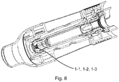
- a medicament delivery device comprising a nozzle device according to the first aspect.
- the nozzle device is the delivery member of the medicament delivery device.
- the medicament delivery device is configured such that medicament passes through the nozzle device during administration to thereby atomise the medicament, creating an aerosol.
- a method of manufacturing a nozzle device for atomisation of a liquid comprising: a) providing a first wafer, c) providing a sieve-side membrane layer onto a first side of the first wafer, d) providing sieve-side orifices in the sieve-side membrane layer thereby obtaining a sieve-side membrane, e) providing a first cavity portion in the first wafer, extending to the sieve-side membrane, f) providing a second wafer, h) providing a spray-side membrane layer onto a first side of the second wafer, i) providing spray-side orifices in the spray-side membrane layer thereby obtaining a spray-side membrane, j) providing a second cavity portion in the second wafer, extending to the spray-side membrane, and k) bonding a second side of the first wafer with a second side of the second wafer thereby forming a substrate, with the sieve-side membrane forming
- Steps f) to j) may for example be carried out prior to steps a) to e).
- steps d), e), i) and j) involves etching.
- step j) involves providing a plurality of second cavity portions in the second wafer, each extending to the spray-side membrane.
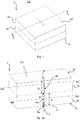
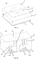
- Fig. 1 shows a first example of a nozzle device configured to atomise liquids.
- the nozzle device 1-1 comprises a substrate 3.
- the substrate 3 comprises a first wafer 3a and a second wafer 3b which have been bonded together, thus forming the substrate 3.
- the substrate 3 has a sieve-side 3c, or filter side, and a spray-side 3d arranged opposite to the sieve-side 3c.
- the nozzle device 1-1 further comprises a sieve-side membrane 5 provided on the sieve-side 3c of the substrate 3.
- the nozzle device 1-1 also comprises a spray-side membrane 7 provided on the spray-side 3d of the substrate 3.
- the cross-sectional area 11 of the first cavity portion 4a is greater than the cross-sectional area 13 of the second cavity portion 4b.
- the cross-sectional area 11 of the first cavity portion 4a is constant along the fluid communication axis 9.
- the cross-sectional area 13 of the second cavity portion 4b is constant along the fluid communication axis 9.
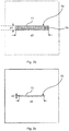
- Fig. 6a illustrates a section along lines E-E. It can be seen that a plurality of second cavity portions 4b extend from the spray-side membrane 7 to one first cavity portion 4a-1 and a plurality of second cavity portions 4b extend from the spray-side membrane 7 to another first cavity portion 4a-2.
- the two first cavity portions are in liquid isolation from each other. They are hence not in fluid communication.
- Each first cavity portion 4a extends to the sieve-side membrane 5.
- fluid communication may be provided from the sieve-side 3c to the spray-side 3d.
- fluid communication is provided between sieve-side orifices 5a of the sieve-side membrane 5 and spray-side orifices 7a of the spray-side membrane 7.
- the layout or configuration of the sieve-side orifices may be essentially any suitable for the particular application.
- the layout or configuration of the spray-side orifices may be essentially any suitable for the particular configuration. It is however beneficial to provide second cavity portion(s) that extends parallel with the corresponding fluid communication axis along its/their entire extension. The same generally also applies to the first cavity portion(s).
- a step d) the sieve-side orifices 5a are provided in the sieve-side membrane layer thereby obtaining the sieve-side membrane 5.
- the sieve-side orifices 5a may for example be obtained using photolithography by providing a suitably patterned photoresist and etching the pattern of sieve-side orifices 5a into the sieve-side membrane layer using for instance reactive ion etching.
- Step d) may also involve removing of the photoresist after the patterning of the sieve-side membrane layer.
- Step e) may involve providing a photoresist onto the second side of the first wafer 3a with a pattern/through-hole to provide the first cavity portion.
- etching techniques to remove a portion of the first wafer 3a, for example deep reactive ion etching, the first cavity portion 4a or cavities 4a may be created.
- the photoresist is thereafter removed from the second side of the first wafer 3a.
- Part of the protective or adhesive layer, exposed by the pattern in the photoresist, is also removed from the second side during step e). The removal of this layer may for example be performed using reactive ion etching
- the protective layer may for example be silicon oxide.
- the protective layer may for example be deposited onto the second wafer 3b by means of thermal oxide deposition.
- a step k) the second side of the first wafer 3a is bonded with the second side of the second wafer 3b thereby forming the substrate 3.
- the sieve-side membrane 5 forms a sieve-side and the spray-side membrane 7 forms a spray-side of the nozzle device 1-1, 1-2, 1-3.
Landscapes
- Chemical & Material Sciences (AREA)
- Chemical Kinetics & Catalysis (AREA)
- Nozzles (AREA)
- Medical Preparation Storing Or Oral Administration Devices (AREA)
- Details Or Accessories Of Spraying Plant Or Apparatus (AREA)
Claims (14)
- Dispositif de buse (1-1 ; 1-2 ; 1-3) pour l'atomisation d'un liquide, dans lequel le dispositif de buse (1-1 ; 1-2 ; 1-3) comprend :un substrat (3),une membrane côté tamis (5) comprenant une pluralité d'orifices côté tamis (5a), la membrane côté tamis (5) étant fournie sur un côté tamis (3c) du substrat (3),une membrane côté pulvérisation (7) comprenant une pluralité d'orifices côté pulvérisation (7a), la membrane côté pulvérisation (7) étant fournie sur un côté pulvérisation (3d) du substrat (3),dans lequel le substrat (3) a une première partie de cavité (4a) s'étendant vers la membrane côté tamis (5), et une deuxième partie de cavité (4b) s'étendant de la première partie de cavité (4a) à la membrane côté pulvérisation (7), ce qui fournit une communication fluidique, le long d'un axe de communication fluidique (9), entre les orifices côté tamis (5a) et les orifices côté pulvérisation (7a), la première partie de cavité (4a) ayant une plus grande aire en coupe transversale (11) qu'une aire en coupe transversale (13) de la deuxième partie de cavité (4b), les coupes transversales étant par rapport à l'axe de communication fluidique (9) ;dans lequel le substrat (3) comprend une première plaquette (3a) pourvue de la première partie de cavité (4a) et une deuxième plaquette (3b) pourvue de la deuxième partie de cavité (4b), la première plaquette (3a) et la deuxième plaquette (3b) étant liées l'une à l'autre pour former le substrat (3).
- Dispositif de buse (1-1 ; 1-2 ; 1-3) tel que revendiqué dans la revendication 1, dans lequel n'importe quelle aire en coupe transversale de la première partie de cavité (4a) est plus grande que n'importe quelle aire en coupe transversale de la deuxième partie de cavité (4b).
- Dispositif de buse (1-1 ; 1-2 ; 1-3) tel que revendiqué dans la revendication 1 ou 2, dans lequel chaque orifice côté pulvérisation (7a) a une aire en coupe transversale supérieure ou égale à l'aire en coupe transversale de n'importe lequel des orifices côté tamis (5a).
- Dispositif de buse (1-1 ; 1-2 ; 1-3) tel que revendiqué dans l'une quelconque des revendications précédentes, dans lequel le nombre d'orifices côté tamis (5a) est supérieur au nombre d'orifices côté pulvérisation (7a).
- Dispositif de buse (1-1 ; 1-2 ; 1-3) tel que revendiqué dans l'une quelconque des revendications précédentes, dans lequel les orifices côté tamis (5a) occupent une aire plus grande sur la membrane côté tamis (5) que celle que les orifices côté pulvérisation (7a) occupent sur la membrane côté pulvérisation (7).
- Dispositif de buse (1-1 ; 1-2 ; 1-3) tel que revendiqué dans l'une quelconque des revendications précédentes, dans lequel le substrat (3) est constitué d'un matériau semi-conducteur.
- Dispositif de buse (1-1 ; 1-2 ; 1-3) tel que revendiqué dans l'une quelconque des revendications précédentes, dans lequel la membrane côté tamis (5) et la membrane côté pulvérisation (7) comprennent l'un parmi une céramique non-oxyde, un oxyde, du silicium ou un métal.
- Dispositif de buse (1-1 ; 1-3) tel que revendiqué dans l'une quelconque des revendications précédentes, dans lequel le substrat (3) comprend une pluralité de deuxièmes parties de cavité (4b) s'étendant de la première partie de cavité (4a) à la membrane côté pulvérisation (7), ce qui fournit une communication fluidique, le long d'un axe de communication fluidique respectif (9), entre les orifices côté tamis (5a) et les orifices côté pulvérisation (7a), la première partie de cavité (4a) ayant une plus grande aire en coupe transversale qu'une aire en coupe transversale de n'importe laquelle des deuxièmes parties de cavité (4b).
- Dispositif de buse (1-1 ; 1-3) tel que revendiqué dans la revendication 8, dans lequel une aire en coupe transversale totale des deuxièmes parties de cavité (4b) par rapport aux axes de communication fluidique (9) est plus petite que l'aire de la membrane côté tamis (5) pourvue des orifices côté tamis (5a).
- Dispositif d'administration de médicament (15) comprenant un dispositif de buse (1-1 ; 1-2 ; 1-3) tel que revendiqué dans l'une quelconque des revendications 1 à 9.
- Dispositif d'administration de médicament (15) tel que revendiqué dans la revendication 10, dans lequel le dispositif d'administration de médicament (15) est un inhalateur ou un applicateur oculaire.
- Procédé de fabrication d'un dispositif de buse (1-1 ; 1-2 ; 1-3) pour atomisation d'un liquide, dans lequel le procédé comprend :a) la fourniture d'une première plaquette (3a),c) la fourniture d'une couche de membrane côté tamis sur un premier côté de la première plaquette (3a),d) la fourniture d'orifices côté tamis (5a) dans la couche de membrane côté tamis ce qui permet d'obtenir une membrane côté tamis (5),e) la fourniture d'une première partie de cavité (4a) dans la première plaquette (3a), s'étendant jusqu'à la membrane côté tamis (5),f) la fourniture d'une deuxième plaquette (3b),h) la fourniture d'une couche de membrane côté pulvérisation sur un premier côté de la deuxième plaquette (3b),i) la fourniture d'orifices côté pulvérisation (7a) dans la couche de membrane côté pulvérisation ce qui permet d'obtenir une membrane côté pulvérisation (7),j) la fourniture d'une deuxième partie de cavité (4b) dans la deuxième plaquette (3b), s'étendant jusqu'à la membrane côté pulvérisation (7), etk) la liaison d'un deuxième côté de la première plaquette (3a) avec un deuxième côté de la deuxième plaquette (3b) ce qui forme un substrat (3), avec la membrane côté tamis (5) formant un côté tamis du dispositif de buse (1-1 ; 1-2 ; 1-3) et la membrane côté pulvérisation (7) formant un côté pulvérisation du dispositif de buse (1-1 ; 1-2; 1-3),
moyennant quoi la deuxième partie de cavité (4b) s'étend de la première partie de cavité (4a) à la membrane côté pulvérisation (7), ce qui fournit une communication fluidique, le long d'un axe de communication fluidique (9), entre les orifices côté tamis (5a) et les orifices côté pulvérisation (7a), la première partie de cavité (4a) ayant une plus grande aire en coupe transversale (11) que l'aire en coupe transversale (13) de la deuxième partie de cavité (4b), la coupe transversale étant par rapport à l'axe de communication fluidique (9). - Procédé tel que revendiqué dans la revendication 12, dans lequel les étapes d), e), i) et j) impliquent une gravure.
- Procédé tel que revendiqué dans la revendication 12 ou 13, dans lequel l'étape j) implique la fourniture d'une pluralité de deuxièmes parties de cavité (4b) dans la deuxième plaquette (3b), s'étendant chacune jusqu'à la membrane côté pulvérisation (7).
Applications Claiming Priority (2)
| Application Number | Priority Date | Filing Date | Title |
|---|---|---|---|
| EP17173695 | 2017-05-31 | ||
| PCT/EP2018/063769 WO2018219798A1 (fr) | 2017-05-31 | 2018-05-25 | Dispositif de buse et méthode de fabrication associée |
Publications (2)
| Publication Number | Publication Date |
|---|---|
| EP3630365A1 EP3630365A1 (fr) | 2020-04-08 |
| EP3630365B1 true EP3630365B1 (fr) | 2021-06-23 |
Family
ID=58873735
Family Applications (1)
| Application Number | Title | Priority Date | Filing Date |
|---|---|---|---|
| EP18727006.1A Active EP3630365B1 (fr) | 2017-05-31 | 2018-05-25 | Dispositif de buse et son procédé de fabrication |
Country Status (7)
| Country | Link |
|---|---|
| US (1) | US11383251B2 (fr) |
| EP (1) | EP3630365B1 (fr) |
| JP (1) | JP6944544B2 (fr) |
| KR (1) | KR102366748B1 (fr) |
| CN (1) | CN110621411B (fr) |
| TW (1) | TWI690345B (fr) |
| WO (1) | WO2018219798A1 (fr) |
Families Citing this family (6)
| Publication number | Priority date | Publication date | Assignee | Title |
|---|---|---|---|---|
| FR3095968B1 (fr) | 2019-05-14 | 2021-10-01 | Aptar France Sas | Dispositif de distribution de produit fluide |
| FR3096089B1 (fr) | 2019-05-14 | 2022-08-05 | Aptar France Sas | Procédé d'assemblage d'une pompe à précompression haute pression |
| FR3096090B1 (fr) | 2019-05-14 | 2022-10-28 | Aptar France Sas | Pompe à précompression haute pression |
| EP4054769B1 (fr) | 2019-11-06 | 2023-11-15 | SHL Medical AG | Puce de buse de pulvérisation |
| KR20230145574A (ko) * | 2021-01-17 | 2023-10-17 | 에스.씨. 존슨 앤 선 인코포레이티드 | 에어로졸 스프레이, 에어로졸 스프레이 생성 방법,및 에어로졸 디스펜싱 시스템 |
| WO2025242695A1 (fr) | 2024-05-21 | 2025-11-27 | Stamford Devices Limited | Plaque d'ouverture de nébuliseur et procédé de fabrication |
Family Cites Families (14)
| Publication number | Priority date | Publication date | Assignee | Title |
|---|---|---|---|---|
| US3990797A (en) * | 1975-05-27 | 1976-11-09 | Xerox Corporation | Diffraction monitoring of Rayleigh mode jets |
| IL107120A (en) * | 1992-09-29 | 1997-09-30 | Boehringer Ingelheim Int | Atomising nozzle and filter and spray generating device |
| JP2790014B2 (ja) | 1993-09-16 | 1998-08-27 | オムロン株式会社 | 超音波式吸入器用メッシュ部材及びその製造方法 |
| WO1998001228A2 (fr) * | 1996-07-08 | 1998-01-15 | Corning Incorporated | Dispositifs d'atomisation a rupture de rayleigh et procedes de fabrication de ces dispositifs |
| CN1126720C (zh) * | 1997-12-19 | 2003-11-05 | 康宁股份有限公司 | 制备金属氧化物烟灰的燃烧器和方法 |
| NL1016030C1 (nl) * | 2000-08-28 | 2002-03-01 | Aquamarijn Holding B V | Sproei inrichting met een nozzleplaat, een nozzleplaat, alsmede werkwijzen ter vervaardiging en voor toepassing van een dergelijke nozzleplaat. |
| EP2165771B1 (fr) | 2000-10-05 | 2012-01-18 | Omron Healthcare Co., Ltd. | Pulvérisateur de liquide |
| KR100400044B1 (ko) | 2001-07-16 | 2003-09-29 | 삼성전자주식회사 | 간격 조절 장치를 가지는 웨이퍼 처리 장치의 샤워 헤드 |
| KR100503482B1 (ko) | 2002-12-30 | 2005-07-25 | 삼성전자주식회사 | 경화변형 방지부를 갖는 모노리식 버블-잉크젯 프린트헤드 및 그 제조방법 |
| ITTO20080980A1 (it) * | 2008-12-23 | 2010-06-24 | St Microelectronics Srl | Processo di fabbricazione di una membrana di ugelli integrata in tecnologia mems per un dispositivo di nebulizzazione e dispositivo di nebulizzazione che utilizza tale membrana |
| NL2002787C2 (en) | 2009-04-23 | 2010-10-26 | Medspray Xmems Bv | Atomising body, atomising device, inhaler, manufacturing method of manufacturing an atomising body and assembly method for assembling an atomising device. |
| JP5157000B1 (ja) * | 2012-03-28 | 2013-03-06 | 田中貴金属工業株式会社 | 噴霧器用メッシュ |
| ES2718678T3 (es) | 2013-07-22 | 2019-07-03 | Koninklijke Philips Nv | Una malla para su uso en un nebulizador y un método para fabricar la misma |
| EP3157681A1 (fr) * | 2014-06-20 | 2017-04-26 | Medspray B.V. | Aérosol ou dispositif de pulvérisation, unité de buse de pulvérisation et procédé de fabrication associé |
-
2018
- 2018-05-25 WO PCT/EP2018/063769 patent/WO2018219798A1/fr not_active Ceased
- 2018-05-25 EP EP18727006.1A patent/EP3630365B1/fr active Active
- 2018-05-25 CN CN201880031702.2A patent/CN110621411B/zh active Active
- 2018-05-25 US US16/616,359 patent/US11383251B2/en active Active
- 2018-05-25 JP JP2019566305A patent/JP6944544B2/ja active Active
- 2018-05-25 KR KR1020197035298A patent/KR102366748B1/ko active Active
- 2018-05-28 TW TW107118135A patent/TWI690345B/zh active
Also Published As
| Publication number | Publication date |
|---|---|
| WO2018219798A1 (fr) | 2018-12-06 |
| KR20190140061A (ko) | 2019-12-18 |
| JP6944544B2 (ja) | 2021-10-06 |
| CN110621411B (zh) | 2021-08-10 |
| CN110621411A (zh) | 2019-12-27 |
| TW201902523A (zh) | 2019-01-16 |
| US11383251B2 (en) | 2022-07-12 |
| JP2020521633A (ja) | 2020-07-27 |
| EP3630365A1 (fr) | 2020-04-08 |
| TWI690345B (zh) | 2020-04-11 |
| KR102366748B1 (ko) | 2022-02-23 |
| US20200094268A1 (en) | 2020-03-26 |
Similar Documents
| Publication | Publication Date | Title |
|---|---|---|
| EP3630365B1 (fr) | Dispositif de buse et son procédé de fabrication | |
| JP2025092774A (ja) | 低減されたクロストークを有する流体吐出方法 | |
| AU729427B2 (en) | Gas-assisted atomizing device | |
| EP2094490B1 (fr) | Modèle d'un revêtement non mouillant sur un éjecteur de fluide et appareil | |
| CN111902179B (zh) | 用于吸入装置的喷雾嘴 | |
| JP2013230698A (ja) | プリントヘッド | |
| CN108698405A (zh) | 流体喷射装置 | |
| ITTO20080980A1 (it) | Processo di fabbricazione di una membrana di ugelli integrata in tecnologia mems per un dispositivo di nebulizzazione e dispositivo di nebulizzazione che utilizza tale membrana | |
| TW201927415A (zh) | 噴霧噴嘴晶片和包含有該晶片的藥物輸送裝置 | |
| KR20220020283A (ko) | 미세유체 디바이스 및 그 제조 방법 | |
| US20120268527A1 (en) | Flow-through ejection system including compliant membrane transducer | |
| EP1200198B1 (fr) | Element d'actionneur destine a un microdiffuseur et son procede de realisation | |
| EP3797001B1 (fr) | Ensemble de micro-buses | |
| CN121338985A (zh) | 在喷嘴行的一个或两个边缘区域中具有减小的直径的穿孔的板 | |
| US8517516B2 (en) | Flow-through liquid ejection using compliant membrane transducer | |
| US8506039B2 (en) | Flow-through ejection system including compliant membrane transducer | |
| TWI766220B (zh) | 噴霧噴嘴晶片、包含有該晶片的藥物輸送裝置、和製造該晶片的方法 | |
| JP4163075B2 (ja) | ノズルプレートの製造方法 | |
| WO2025022345A1 (fr) | Buse destinée à être utilisée dans des micropompes | |
| KR101249723B1 (ko) | 액적 토출용 노즐 제조 방법 및 이를 이용해 제조된 노즐을 이용한 정전식 액적 토출 장치 | |
| US20120268528A1 (en) | Flow-through liquid ejection using compliant membrane transducer | |
| GB2482873A (en) | Droplet generator for dispensing multiple streams of uniform liquid droplets | |
| HK40122683A (zh) | 微流体装置和生产方法 | |
| EP2699424A1 (fr) | Système d'éjection à écoulement traversant comprenant un transducteur à membrane élastique | |
| WO2012145277A1 (fr) | Système d'éjection à circulation directe comprenant un transducteur à membrane souple |
Legal Events
| Date | Code | Title | Description |
|---|---|---|---|
| STAA | Information on the status of an ep patent application or granted ep patent |
Free format text: STATUS: UNKNOWN |
|
| STAA | Information on the status of an ep patent application or granted ep patent |
Free format text: STATUS: THE INTERNATIONAL PUBLICATION HAS BEEN MADE |
|
| PUAI | Public reference made under article 153(3) epc to a published international application that has entered the european phase |
Free format text: ORIGINAL CODE: 0009012 |
|
| STAA | Information on the status of an ep patent application or granted ep patent |
Free format text: STATUS: REQUEST FOR EXAMINATION WAS MADE |
|
| 17P | Request for examination filed |
Effective date: 20191111 |
|
| AK | Designated contracting states |
Kind code of ref document: A1 Designated state(s): AL AT BE BG CH CY CZ DE DK EE ES FI FR GB GR HR HU IE IS IT LI LT LU LV MC MK MT NL NO PL PT RO RS SE SI SK SM TR |
|
| AX | Request for extension of the european patent |
Extension state: BA ME |
|
| DAV | Request for validation of the european patent (deleted) | ||
| DAX | Request for extension of the european patent (deleted) | ||
| GRAP | Despatch of communication of intention to grant a patent |
Free format text: ORIGINAL CODE: EPIDOSNIGR1 |
|
| STAA | Information on the status of an ep patent application or granted ep patent |
Free format text: STATUS: GRANT OF PATENT IS INTENDED |
|
| INTG | Intention to grant announced |
Effective date: 20210317 |
|
| GRAS | Grant fee paid |
Free format text: ORIGINAL CODE: EPIDOSNIGR3 |
|
| GRAA | (expected) grant |
Free format text: ORIGINAL CODE: 0009210 |
|
| STAA | Information on the status of an ep patent application or granted ep patent |
Free format text: STATUS: THE PATENT HAS BEEN GRANTED |
|
| AK | Designated contracting states |
Kind code of ref document: B1 Designated state(s): AL AT BE BG CH CY CZ DE DK EE ES FI FR GB GR HR HU IE IS IT LI LT LU LV MC MK MT NL NO PL PT RO RS SE SI SK SM TR |
|
| REG | Reference to a national code |
Ref country code: GB Ref legal event code: FG4D |
|
| REG | Reference to a national code |
Ref country code: CH Ref legal event code: EP |
|
| REG | Reference to a national code |
Ref country code: DE Ref legal event code: R096 Ref document number: 602018019012 Country of ref document: DE Ref country code: AT Ref legal event code: REF Ref document number: 1403835 Country of ref document: AT Kind code of ref document: T Effective date: 20210715 |
|
| REG | Reference to a national code |
Ref country code: IE Ref legal event code: FG4D |
|
| REG | Reference to a national code |
Ref country code: LT Ref legal event code: MG9D |
|
| PG25 | Lapsed in a contracting state [announced via postgrant information from national office to epo] |
Ref country code: FI Free format text: LAPSE BECAUSE OF FAILURE TO SUBMIT A TRANSLATION OF THE DESCRIPTION OR TO PAY THE FEE WITHIN THE PRESCRIBED TIME-LIMIT Effective date: 20210623 Ref country code: HR Free format text: LAPSE BECAUSE OF FAILURE TO SUBMIT A TRANSLATION OF THE DESCRIPTION OR TO PAY THE FEE WITHIN THE PRESCRIBED TIME-LIMIT Effective date: 20210623 Ref country code: LT Free format text: LAPSE BECAUSE OF FAILURE TO SUBMIT A TRANSLATION OF THE DESCRIPTION OR TO PAY THE FEE WITHIN THE PRESCRIBED TIME-LIMIT Effective date: 20210623 Ref country code: BG Free format text: LAPSE BECAUSE OF FAILURE TO SUBMIT A TRANSLATION OF THE DESCRIPTION OR TO PAY THE FEE WITHIN THE PRESCRIBED TIME-LIMIT Effective date: 20210923 |
|
| REG | Reference to a national code |
Ref country code: AT Ref legal event code: MK05 Ref document number: 1403835 Country of ref document: AT Kind code of ref document: T Effective date: 20210623 |
|
| PG25 | Lapsed in a contracting state [announced via postgrant information from national office to epo] |
Ref country code: GR Free format text: LAPSE BECAUSE OF FAILURE TO SUBMIT A TRANSLATION OF THE DESCRIPTION OR TO PAY THE FEE WITHIN THE PRESCRIBED TIME-LIMIT Effective date: 20210924 Ref country code: NO Free format text: LAPSE BECAUSE OF FAILURE TO SUBMIT A TRANSLATION OF THE DESCRIPTION OR TO PAY THE FEE WITHIN THE PRESCRIBED TIME-LIMIT Effective date: 20210923 Ref country code: LV Free format text: LAPSE BECAUSE OF FAILURE TO SUBMIT A TRANSLATION OF THE DESCRIPTION OR TO PAY THE FEE WITHIN THE PRESCRIBED TIME-LIMIT Effective date: 20210623 Ref country code: RS Free format text: LAPSE BECAUSE OF FAILURE TO SUBMIT A TRANSLATION OF THE DESCRIPTION OR TO PAY THE FEE WITHIN THE PRESCRIBED TIME-LIMIT Effective date: 20210623 Ref country code: SE Free format text: LAPSE BECAUSE OF FAILURE TO SUBMIT A TRANSLATION OF THE DESCRIPTION OR TO PAY THE FEE WITHIN THE PRESCRIBED TIME-LIMIT Effective date: 20210623 |
|
| REG | Reference to a national code |
Ref country code: NL Ref legal event code: MP Effective date: 20210623 |
|
| PG25 | Lapsed in a contracting state [announced via postgrant information from national office to epo] |
Ref country code: SK Free format text: LAPSE BECAUSE OF FAILURE TO SUBMIT A TRANSLATION OF THE DESCRIPTION OR TO PAY THE FEE WITHIN THE PRESCRIBED TIME-LIMIT Effective date: 20210623 Ref country code: ES Free format text: LAPSE BECAUSE OF FAILURE TO SUBMIT A TRANSLATION OF THE DESCRIPTION OR TO PAY THE FEE WITHIN THE PRESCRIBED TIME-LIMIT Effective date: 20210623 Ref country code: EE Free format text: LAPSE BECAUSE OF FAILURE TO SUBMIT A TRANSLATION OF THE DESCRIPTION OR TO PAY THE FEE WITHIN THE PRESCRIBED TIME-LIMIT Effective date: 20210623 Ref country code: SM Free format text: LAPSE BECAUSE OF FAILURE TO SUBMIT A TRANSLATION OF THE DESCRIPTION OR TO PAY THE FEE WITHIN THE PRESCRIBED TIME-LIMIT Effective date: 20210623 Ref country code: PT Free format text: LAPSE BECAUSE OF FAILURE TO SUBMIT A TRANSLATION OF THE DESCRIPTION OR TO PAY THE FEE WITHIN THE PRESCRIBED TIME-LIMIT Effective date: 20211025 Ref country code: NL Free format text: LAPSE BECAUSE OF FAILURE TO SUBMIT A TRANSLATION OF THE DESCRIPTION OR TO PAY THE FEE WITHIN THE PRESCRIBED TIME-LIMIT Effective date: 20210623 Ref country code: RO Free format text: LAPSE BECAUSE OF FAILURE TO SUBMIT A TRANSLATION OF THE DESCRIPTION OR TO PAY THE FEE WITHIN THE PRESCRIBED TIME-LIMIT Effective date: 20210623 Ref country code: AT Free format text: LAPSE BECAUSE OF FAILURE TO SUBMIT A TRANSLATION OF THE DESCRIPTION OR TO PAY THE FEE WITHIN THE PRESCRIBED TIME-LIMIT Effective date: 20210623 Ref country code: CZ Free format text: LAPSE BECAUSE OF FAILURE TO SUBMIT A TRANSLATION OF THE DESCRIPTION OR TO PAY THE FEE WITHIN THE PRESCRIBED TIME-LIMIT Effective date: 20210623 |
|
| PG25 | Lapsed in a contracting state [announced via postgrant information from national office to epo] |
Ref country code: PL Free format text: LAPSE BECAUSE OF FAILURE TO SUBMIT A TRANSLATION OF THE DESCRIPTION OR TO PAY THE FEE WITHIN THE PRESCRIBED TIME-LIMIT Effective date: 20210623 |
|
| REG | Reference to a national code |
Ref country code: DE Ref legal event code: R097 Ref document number: 602018019012 Country of ref document: DE |
|
| PG25 | Lapsed in a contracting state [announced via postgrant information from national office to epo] |
Ref country code: DK Free format text: LAPSE BECAUSE OF FAILURE TO SUBMIT A TRANSLATION OF THE DESCRIPTION OR TO PAY THE FEE WITHIN THE PRESCRIBED TIME-LIMIT Effective date: 20210623 |
|
| PLBE | No opposition filed within time limit |
Free format text: ORIGINAL CODE: 0009261 |
|
| STAA | Information on the status of an ep patent application or granted ep patent |
Free format text: STATUS: NO OPPOSITION FILED WITHIN TIME LIMIT |
|
| 26N | No opposition filed |
Effective date: 20220324 |
|
| PG25 | Lapsed in a contracting state [announced via postgrant information from national office to epo] |
Ref country code: AL Free format text: LAPSE BECAUSE OF FAILURE TO SUBMIT A TRANSLATION OF THE DESCRIPTION OR TO PAY THE FEE WITHIN THE PRESCRIBED TIME-LIMIT Effective date: 20210623 |
|
| PG25 | Lapsed in a contracting state [announced via postgrant information from national office to epo] |
Ref country code: IT Free format text: LAPSE BECAUSE OF FAILURE TO SUBMIT A TRANSLATION OF THE DESCRIPTION OR TO PAY THE FEE WITHIN THE PRESCRIBED TIME-LIMIT Effective date: 20210623 |
|
| REG | Reference to a national code |
Ref country code: BE Ref legal event code: MM Effective date: 20220531 |
|
| PG25 | Lapsed in a contracting state [announced via postgrant information from national office to epo] |
Ref country code: MC Free format text: LAPSE BECAUSE OF FAILURE TO SUBMIT A TRANSLATION OF THE DESCRIPTION OR TO PAY THE FEE WITHIN THE PRESCRIBED TIME-LIMIT Effective date: 20210623 Ref country code: LU Free format text: LAPSE BECAUSE OF NON-PAYMENT OF DUE FEES Effective date: 20220525 |
|
| PG25 | Lapsed in a contracting state [announced via postgrant information from national office to epo] |
Ref country code: IE Free format text: LAPSE BECAUSE OF NON-PAYMENT OF DUE FEES Effective date: 20220525 |
|
| PG25 | Lapsed in a contracting state [announced via postgrant information from national office to epo] |
Ref country code: BE Free format text: LAPSE BECAUSE OF NON-PAYMENT OF DUE FEES Effective date: 20220531 |
|
| P01 | Opt-out of the competence of the unified patent court (upc) registered |
Effective date: 20230425 |
|
| PG25 | Lapsed in a contracting state [announced via postgrant information from national office to epo] |
Ref country code: MK Free format text: LAPSE BECAUSE OF FAILURE TO SUBMIT A TRANSLATION OF THE DESCRIPTION OR TO PAY THE FEE WITHIN THE PRESCRIBED TIME-LIMIT Effective date: 20210623 Ref country code: CY Free format text: LAPSE BECAUSE OF FAILURE TO SUBMIT A TRANSLATION OF THE DESCRIPTION OR TO PAY THE FEE WITHIN THE PRESCRIBED TIME-LIMIT Effective date: 20210623 |
|
| PG25 | Lapsed in a contracting state [announced via postgrant information from national office to epo] |
Ref country code: HU Free format text: LAPSE BECAUSE OF FAILURE TO SUBMIT A TRANSLATION OF THE DESCRIPTION OR TO PAY THE FEE WITHIN THE PRESCRIBED TIME-LIMIT; INVALID AB INITIO Effective date: 20180525 |
|
| PG25 | Lapsed in a contracting state [announced via postgrant information from national office to epo] |
Ref country code: TR Free format text: LAPSE BECAUSE OF FAILURE TO SUBMIT A TRANSLATION OF THE DESCRIPTION OR TO PAY THE FEE WITHIN THE PRESCRIBED TIME-LIMIT Effective date: 20210623 |
|
| PG25 | Lapsed in a contracting state [announced via postgrant information from national office to epo] |
Ref country code: MT Free format text: LAPSE BECAUSE OF FAILURE TO SUBMIT A TRANSLATION OF THE DESCRIPTION OR TO PAY THE FEE WITHIN THE PRESCRIBED TIME-LIMIT Effective date: 20210623 |
|
| PGFP | Annual fee paid to national office [announced via postgrant information from national office to epo] |
Ref country code: DE Payment date: 20250528 Year of fee payment: 8 |
|
| PGFP | Annual fee paid to national office [announced via postgrant information from national office to epo] |
Ref country code: GB Payment date: 20250520 Year of fee payment: 8 |
|
| PGFP | Annual fee paid to national office [announced via postgrant information from national office to epo] |
Ref country code: FR Payment date: 20250526 Year of fee payment: 8 |
|
| PGFP | Annual fee paid to national office [announced via postgrant information from national office to epo] |
Ref country code: CH Payment date: 20250601 Year of fee payment: 8 |