EP3630502B1 - Modulare radendanordnung und installationsverfahren - Google Patents
Modulare radendanordnung und installationsverfahren Download PDFInfo
- Publication number
- EP3630502B1 EP3630502B1 EP18805594.1A EP18805594A EP3630502B1 EP 3630502 B1 EP3630502 B1 EP 3630502B1 EP 18805594 A EP18805594 A EP 18805594A EP 3630502 B1 EP3630502 B1 EP 3630502B1
- Authority
- EP
- European Patent Office
- Prior art keywords
- assembly
- retainer
- outboard
- hub
- bore
- Prior art date
- Legal status (The legal status is an assumption and is not a legal conclusion. Google has not performed a legal analysis and makes no representation as to the accuracy of the status listed.)
- Active
Links
Images


Classifications
-
- B—PERFORMING OPERATIONS; TRANSPORTING
- B60—VEHICLES IN GENERAL
- B60B—VEHICLE WHEELS; CASTORS; AXLES FOR WHEELS OR CASTORS; INCREASING WHEEL ADHESION
- B60B27/00—Hubs
- B60B27/02—Hubs adapted to be rotatably arranged on axle
-
- B—PERFORMING OPERATIONS; TRANSPORTING
- B60—VEHICLES IN GENERAL
- B60B—VEHICLE WHEELS; CASTORS; AXLES FOR WHEELS OR CASTORS; INCREASING WHEEL ADHESION
- B60B35/00—Axle units; Parts thereof ; Arrangements for lubrication of axles
- B60B35/02—Dead axles, i.e. not transmitting torque
- B60B35/025—Dead axles, i.e. not transmitting torque the wheels being removable
-
- B—PERFORMING OPERATIONS; TRANSPORTING
- B60—VEHICLES IN GENERAL
- B60B—VEHICLE WHEELS; CASTORS; AXLES FOR WHEELS OR CASTORS; INCREASING WHEEL ADHESION
- B60B27/00—Hubs
- B60B27/001—Hubs with roller-bearings
-
- B—PERFORMING OPERATIONS; TRANSPORTING
- B60—VEHICLES IN GENERAL
- B60B—VEHICLE WHEELS; CASTORS; AXLES FOR WHEELS OR CASTORS; INCREASING WHEEL ADHESION
- B60B35/00—Axle units; Parts thereof ; Arrangements for lubrication of axles
- B60B35/02—Dead axles, i.e. not transmitting torque
- B60B35/04—Dead axles, i.e. not transmitting torque straight
-
- B—PERFORMING OPERATIONS; TRANSPORTING
- B60—VEHICLES IN GENERAL
- B60B—VEHICLE WHEELS; CASTORS; AXLES FOR WHEELS OR CASTORS; INCREASING WHEEL ADHESION
- B60B2380/00—Bearings
- B60B2380/10—Type
- B60B2380/14—Roller bearings
-
- B—PERFORMING OPERATIONS; TRANSPORTING
- B60—VEHICLES IN GENERAL
- B60B—VEHICLE WHEELS; CASTORS; AXLES FOR WHEELS OR CASTORS; INCREASING WHEEL ADHESION
- B60B27/00—Hubs
- B60B27/0073—Hubs characterised by sealing means
-
- B—PERFORMING OPERATIONS; TRANSPORTING
- B60—VEHICLES IN GENERAL
- B60B—VEHICLE WHEELS; CASTORS; AXLES FOR WHEELS OR CASTORS; INCREASING WHEEL ADHESION
- B60B27/00—Hubs
- B60B27/0078—Hubs characterised by the fixation of bearings
-
- B—PERFORMING OPERATIONS; TRANSPORTING
- B60—VEHICLES IN GENERAL
- B60B—VEHICLE WHEELS; CASTORS; AXLES FOR WHEELS OR CASTORS; INCREASING WHEEL ADHESION
- B60B27/00—Hubs
- B60B27/0078—Hubs characterised by the fixation of bearings
- B60B27/0084—Hubs characterised by the fixation of bearings caulking to fix inner race
-
- F—MECHANICAL ENGINEERING; LIGHTING; HEATING; WEAPONS; BLASTING
- F16—ENGINEERING ELEMENTS AND UNITS; GENERAL MEASURES FOR PRODUCING AND MAINTAINING EFFECTIVE FUNCTIONING OF MACHINES OR INSTALLATIONS; THERMAL INSULATION IN GENERAL
- F16C—SHAFTS; FLEXIBLE SHAFTS; ELEMENTS OR CRANKSHAFT MECHANISMS; ROTARY BODIES OTHER THAN GEARING ELEMENTS; BEARINGS
- F16C2326/00—Articles relating to transporting
- F16C2326/01—Parts of vehicles in general
- F16C2326/02—Wheel hubs or castors
Definitions
- a wheelend assembly typically includes a main body or hub defining a cavity that receives an axle, spindle, or the like.
- the main body houses an inboard bearing assembly, a spacer, and an outboard bearing assembly.
- the spacer generally acts to maintain the distance between the inboard bearing assembly and the outboard bearing assembly and may allow limited movement of both such that the bearing and the associated race/cup can properly seat.
- the inboard bearing assembly is on the inboard side and is bounded by an oil seal.
- the oil seal secures the inboard side of the wheelend assembly to inhibit the inboard bearing, the spacer, etc. from moving further.
- An end cap is typically placed over the outboard bearing and coupled to the main body to inhibit the wheelend assembly from unloading to the outboard side of the main body.
- the bearings may be misaligned with the axle outer surface when installing the wheelend assembly onto the axle.
- An alignment insert such as a sleeve or the like, may be used to hold the outboard bearing assembly and spacer in alignment until the axle is inserted into the space and pushes the alignment insert out of the main body.
- axle nut or spindle nut
- the axle nut presses the outboard bearing assembly against the spacer and seats the outboard bearing in its race/cup.
- the axle nut also presses the inboard bearing assembly against an axle shoulder that seats the inboard bearing in its race/cup.
- DE19956838C1 discloses a wheel mounting for a trailer axle.
- the wheel mounting has a wheel hub supported from the end of an axle shaft by front and rear roller bearings with a sleeve enclosing the axel shaft between the inner bearing rings of the front and rear roller bearings.
- the sleeve is elastic in the axial direction, e.g. by incorporating flexure regions.
- a unitized wheelend assembly in the invention, includes a hub having an inboard side and an outboard side defining a cavity.
- the inboard side of the hub is bounded by an oil seal and the outboard side is bounded by a retainer.
- the retainer retains an inboard bearing assembly, a spacer, an outboard bearing assembly and a spindle nut in the unitized wheelend assembly.
- the unitized wheelend assembly may include an alignment insert internal to the outboard bearing assembly and the spacer.
- the retainer comprises a flanged surface and a plurality of bolt bores arranged on the flanged surface to allow bolts on the hub to be inserted through the bolt bores, such that the retainer is releaseably coupled to the hub by at least one nut being threaded on at least one bolt.
- the retainer comprises opposed protruding surfaces each of which having at least one bore.
- a spring clip is coupled to the opposed protruding surfaces, the spring clip comprising an engagement bore having a first position aligned one of the at least one bore such that a bolt on the hub is moveable through the one of the at least one bore and the engagement bore and a second position where an edge of the engagement bore is configured to engage the bolt to inhibit removal of the retainer from the hub.
- Unitized in this particular exemplary embodiment means the entire assembly is held together prior to installation on the axle/spindle and, once engaged with the axle/spindle, the retainer need only be removed for the unitized wheelend assembly to be ready for use or operation.
- the technology of the present application will be described with relation to exemplary embodiments.
- the word "exemplary” is used herein to mean “serving as an example, instance, or illustration.” Any embodiment described herein as “exemplary” is not necessarily to be construed as preferred or advantageous over other embodiments. Additionally, unless specifically identified otherwise, all embodiments described herein should be considered exemplary.
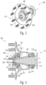
- the unitized wheelend assembly 100 is defined as unitized because it provides an assembly inclusive of a hub or main body 105 defining, among other things a cavity 106, an inboard oil seal 110, an inboard bearing assembly 115 having a bearing 116, a bearing race 117, and a bearing cup 118, an outboard bearing assembly 120 having a bearing 121, a bearing race 122, and a bearing cup 123, a spacer 124 residing between the inboard bearing assembly 115 and the outboard bearing assembly 120, a unitized spindle nut assembly 125 having a washer 126, a collar 127, and a nut 128, and a retainer 130, which is explained further below.
- the cavity 106 may hold lubrication such as oil or the like as required.
- the unitized wheelend assembly 100 is shown partially on spindle 5.
- an alignment insert 135 may be used in unitized wheelend assembly 100. The alignment insert 135 maintains the alignment of the outboard bearing assembly 120 and spacer 124 until the unitized wheelend assembly 100 is placed on the spindle 5.
- the retainer 130 engages the spindle nut assembly 125.
- the nut 128 of the spindle nut assembly 125 generally has a shape 129, such as a hexagonal, octagonal, or other generally non-round shape.
- the retainer 130 has a bore 131 and a counter bore 132 with a shape 133 to cooperatively engage the shape 129.
- the shape 129 and shape 133 may, in certain embodiments, be round but will generally have other key/keyway engagement to inhibit relative rotation.
- the retainer 130 couples to the hub 105 to form the unitized wheelend assembly 100 that allows a single assembly to be placed on the spindle 5.
- FIGS. 3 and 4 show a unitized wheelend assembly 200 configured to for use with an alternative hub 205 or main body 205.
- the hub 205 in this exemplary embodiment, has internal threads 206.
- the main body 205 defines a cavity 207.
- the unitized wheelend assembly 200 includes the hub 205, an inboard oil seal 210, an inboard bearing assembly 215 having a bearing 216, a bearing race 217, and a bearing cup 218, an outboard bearing assembly 220 having a bearing 221, a bearing race 222, and a bearing cup 223, a spacer 224 residing between the inboard bearing assembly 215 and the outboard bearing assembly 220, a unitized spindle nut assembly 225 having a washer 226, a collar 227, and a nut 228 (in this exemplary spindle nut 225), and a retainer 230.
- the cavity 207 may hold lubrication such as oil or the like as required.
- the unitized wheelend assembly 200 is shown on spindle 5.
- an alignment insert 235 may be used in unitized wheelend assembly 200. The alignment insert 235 maintains the alignment of the outboard bearing assembly 220 and spacer 225 until the unitized wheelend assembly 200 is placed on the spindle 5.
- the retainer 230 engages the spindle nut assembly 225.
- the nut 228 of the spindle nut assembly 225 generally has a shape 229, such as a hexagonal or octagonal shape.
- the retainer 230 has a bore 231 and a counter bore 232 with a shape 233 to operatively engage the shape 229.
- the retainer 230 couples to the hub to form the unitized wheelend assembly 200, as explained below, that allows a single assembly to be placed on the spindle 5.
- An installer or operator places the unitized wheel end assembly 100, 200 on spindle 5 by aligning the bore 10 of the unitized wheel end assembly 100, 200 with the spindle 5.
- the unitized wheel end assembly 100, 200 is pushed onto the spindle 5 until spindle 5 extends from the outboard side of the bore 131, 231 of the retainer 130, 230. If the unitized wheelend assembly 100, 200 included the optional alignment insert 135, 235, the alignment insert 135, 235 is forced out of the unitized wheel end assembly 100, 200 through the bore 131, 231 by the spindle 5 as it move through the unitized wheelend assembly 100, 200.
- the unitized wheelend assembly 100, 200 is aligned, typically by spinning the unitized wheelend assembly 100, 200 on the spindle 5.
- a key such as a tang (not specifically shown), on the inside surface of the spindle nut assembly 125, 225, engages a keyway (not specifically shown) on the outer surface of the spindle 5.
- the unitized wheelend assembly 100, 200 is seated by continued rotation of the unitized wheelend assembly 100, 200.
- the retainer 130, 230 is removed once the unitized wheelend assembly 100, 200 is seated on the spindle 5.
- the retainer 130, 230 can be removed once the unitized wheelend assembly 100, 200 is aligned.
- the installer, operator may finish seating the unitized wheelend assembly 100, 200 on the spindle 5 using a torque wrench or the like.
- Figure 5 shows a top view and a cross section view of a retainer 500.
- the retainer 500 could be used for either retainer 130, 230 above. Dimensional information shown on figure 5 and any other figure should be considered exemplary of a designed prototype and not otherwise limiting.
- the retainer 500 has a cylindrical body 505 and a flanged surface 510.
- the flanged surface 510 includes a number of bolt bores 506 and a central bore 515.
- the central bore 515 has a shape 520 designed to engage the shape of the spindle nut assembly 125, 225.
- the bolt bores 506 are spaced to align with the inner bolts on the hub 100.
- the retainer 500 may be maintained on the hub 100 by one or more nuts (not specifically shown in figure 5 ).
- the retainer 500 may have a circular central bore 515 with a counter bore 525 having the shape 520.
- figure 6 shows a pair of adjustment screws 530 designed to engage the spindle nut assembly 125, 225 in certain embodiments where the spindle nut assembly 125, 225 is modified to facilitate the engagement.
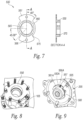
- Figure 7 shows a similar retainer 550.
- Retainer 550 has a cylindrical body 555 and a flanged surface 560 with opposed protruding surfaces 561 where each opposed protruding surface 561 has at least one bolt bore 566. While the various embodiments show the protruding surfaces, such as protruding surfaces 561, as opposed, the protruding surfaces may be asymmetrical in certain embodiments such that they are not opposed, but rather offset.
- the retainer 550 has a central bore 565 that is generally cylindrical and a counter bore 570 having a shape 575 designed to engage the shape of the spindle nut assembly 125, 225.
- the flanged surface 560 generally has a radius sufficiently small so the flanged surface does not engage any of the inner bolts.
- the opposed protruding surface 561 have a radius that allows the bolt bore 566 to align with the inner bolts.
- Figure 8 shows a prototype design of retainer 550 on the hub 105.
- Figure 9 shows modified retainer 550A for use with unitized assembly 200.
- Modified retainer 550A has a cylindrical body 555 with opposed protruding surfaces 561A proximal an inboard edge 580 at the terminal end of the counter bore 570.
- the opposed protruding surfaces 561A each have at least one bolt bore 566A to receive a bolt 567 to couple the modified retainer 550A to the hub 205.
- Figures 10 and 11 show another retainer 600 and 600A.
- the retainers 600 and 600A both have a cylindrical body 605 with a flanged surface 610 having opposed protruding surfaces 615.
- Each of the retainers 600 and 600A have a means for engaging 620 the bolts of the hub 105, which will be explained further below.
- the cylindrical body 605 has a counter bore 606 forming a shape 607 that engages an appropriate spindle nut assembly.
- the retainer 600 has opposed protruding surfaces 615.
- the protruding surfaces 615 are formed by fingers 621 extending outwardly from the flanged surface 610.
- the fingers 621 are separated by a gap 622.
- a spring member 623 is coupled to each finger 621, which spring members 623 are opposed to each other.
- the spring member 623 is a resilient clip, such as a spring metal or composite material.
- Each spring member 623 terminates at an engagement member 624 that can releasably engage a thread of the bolts on the hub 105.
- the engagement member 624 is a protrusion that engages a thread of the bolt in this exemplary embodiment.
- Other engagement members may include other friction fits or snap fit members.
- Extending from the engagement member 624 is a lever 625. Pinching the lever 625 causes the engagement member or members 624 to release from the thread allowing the retainer 600 to be removed by the installer or operator.
- the retainer 600A has opposed protruding surfaces 615.
- the protruding surfaces 615 are formed by fingers 630 that are separated by a gap 631.
- the fingers 630 may form asymmetrical surfaces as shown by finger 630 1 having a larger surface area than finger 630 2 .
- a spring clip 632 is attached to one of the fingers 630 (or the flanged surface 610).
- the spring clip 632 includes an engagement member 633 that can engage the bolts on the hub 105.
- the spring clip 632 terminates in a tab 634 that can be used to manipulate the spring clip 632 such that the engagement member 633 engages or releases the bolt.
- a stop 635 may be provided to inhibit the amount of movement spring clip 632.
- the engagement member 633 (or 625) may operate similar to a ratchet such that it can slip onto the bolts while being installed, but cannot be removed without disengaging the engagement member. While shown as a single engagement member 633, the engagement member 633 may be a number of protrusions and/or threads to engage the threads of the bolts.
- Figure 12 shows a retainer 600B configured for unitized wheelend assembly 200.
- the retainer 600B comprises a cylindrical body 640 having a bore 645 and a counter bore 650.
- the counter bore 650 has a shape 651 configured to engage an appropriate spindle nut.
- the retainer 600B has a flanged surface 655 including protruding tabs 660 and opposed protruding surfaces 665.
- the protruding tabs 660 in this exemplary embodiment comprise spring clips 661 having a retaining lip 662. The spring clips 661 are compressed to fit into a corresponding bore on the hub 205.
- the retaining lip 662 moves through the bore and catches on an inboard side of the hub 205.
- FIG. 13 shows a similar retainer 600C.
- Retainer 600C has protruding tabs 660 forming bores 661A.
- a connector 662A such as a push pin or the like, is inserted into the bore 661A.
- the connector 662A extends through the bore 661A and a corresponding bore in the hub 205.
- the fins 663A act as ratchets to inhibit the connector 662A from falling out.
- a retainer 700 is shown.
- the retainer 700 is similar to the retainer 550, and such similarities will not be further explained.
- the retainer 700 has opposed protruding surfaces 661 with a retaining slot 701 formed in the protruding surfaces 661 proximate the bolt bore 566.
- a spring clip 702 has a first end 703 formed to cooperatively fit within slot 701 and a second end 704 arranged at an angle 705 to the first end 703 to form the spring clip 702.
- the second end 704 has an engagement bore 706 and a tab 707.
- the spring clip 702 is biased such that the second end 704 positioned distal from the opposed protruding surfaces 661.
- the tabs 707 are depressed until the engagement bore 706 is aligned with the bolt bore 566.
- the bolt on the hub 105 is freely insertable when the engagement bore 706 is held in alignment with the bolt bore 566.
- the tabs 707 are released allowing the second end to return towards it unbiased position.
- An edge 708 or the engagement bore 706 engages the bolt, such as at a thread, to hold the retainer 700 in place.
- a retainer 750 is shown.
- the retainer 750 is similar to the retainer 600 above.
- the retainer 750 has a cylindrical body 755 having a bore 760 and a counter bore 765.
- the counter bore 765 is shaped to engage a corresponding spindle nut assembly.
- the retainer 750 has a pair of lock mechanisms 770, one on each of the opposed protruding surfaces 561.
- Each lock mechanism 770 has a protruding finger 771 with a bore 772 having a shape 773, which is shown as rectangular in this exemplary embodiment.
- the lock mechanisms 770 have a slot 773.
- a spring clip 774 has a first end 775 sized and shaped to fit within the slot 773.
- a second end 776 of the spring clip forms an acute angle 777 with the first end 775 and is sized and shaped to fit through the bore 772.
- the second end 776 of the spring clip 774 has an engagement bore 778 and terminates in a tab 779. Operation of the spring clip 774 is similar to the spring clip described above.
- the tabs 779 are depressed to align the engagement bore 778 with the bore 772.
- the bolts on hub 105 freely pass through engagement bore 778 when the tabs are pressed.
- the second end 776 decompresses and an edge 780 on the engagement bore 778 frictionally engages the bolt, such as by engaging a thread or the like.
- Figure 18 shows a perspective view of the retainer 750 on the hub 105 where the edge 780 is locked onto a bolt of the hub 105.
- forces tending to push the unitized wheelend assembly 100 parts outboard would force the spring clip 774 against the associated bolt 781 (sometimes referred to as a stud) to resist the force.
- Figure 19 shows a retainer 800 configured for the hub 205.
- the retainer 800 is similar to retainer 600C described above.
- the retainer 800 has a flanged surface 805 with a plurality of alignment bores 810.
- the alignment bores 810 align with bores in the hub 205.
- the alignment bores 810 are sized and shaped to cooperatively engage a pin 812, which may be used to facilitate rotational resistance.
- the alignment bores 810 also are sized and shaped to cooperatively engage one or more fasteners 815.
- Fastener 815 may be the same as connector 662A described above in certain embodiments.
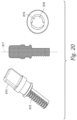
- One specific fastener 815 is shown in figure 20 , which provides a perspective view, a cross sectional view, and a plan view of fastener 815.
- Fastener 815 in this exemplary embodiment, has fins 816 on a single side of the fastener 815 and operates as a cam lock.
- the fastener 815 is offset from its longitudinal axis 817 such that it has a smaller diameter 818 for clearance of rotation and a larger diameter 819.
- the fastener 815 rotates between a locked and unlocked position to allow the retainer 800 to be locked to or removed from the unitized wheelend assembly.
- Figure 21 shows another retainer 900. Similar to other retainers herein, the retainer 900 has a generally cylindrical body 905 with a bore 910 and a counter bore 915. The counter bore 915 generally has a shape 920 configured to engage the shape of the spindle nut associated with the unitized wheelend assembly.
- the retainer 900 further includes a flanged surface 925. A pair of opposed fingers 930 extend from the flanged surface 925. The diameter of the flanged surface 925 is less than the diameter of the bolts. The width of the retainer 900 at the pair of opposed fingers 930 is at least sufficient to allow one or more bores 935 to fit over a corresponding bolt as explained above.
- Each bore 935 is configured to receive a cam nut lock 940, which cam nut lock 940 will be described further below.
- Each of the one or more bores 935 may have a cam nut lock engagement surface 945, which surface is shown slightly raised in the exemplary embodiment.
- the cam nut lock engagement surface 940 facilitates rotation of the cam nut lock 940.
- the cam nut lock engagement surface 945 may extend from an edge 950 of the opposed fingers 930.
- the cam nut lock engagement surface 945 may have a thinner depth than the opposed fingers 930. A thinner depth provides a channel 950 on an inboard facing surface 955.
- FIG 21 also shows a detail of the cam nut lock 940 in isolation for clarity.
- the cam nut lock 940 has a cylindrical base 960 that is configured to be slidingly received in the bore 935.
- An inboard edge 961 of the cylindrical base has a lip 962.
- the lip 962 is configured to engage the surface of the channel 950 or the inboard facing surface 955.
- the lip 962 holds the cam nut lock 940 in rotational engagement with the retainer 900.
- the outboard side 963 of the cylindrical base 960 has a nut 964 with a pair of opposed arms 965, which may act as levers.
- the cam nut lock 940 has a bore 966 sized to receive the aforementioned bolts.
- the cam nut lock 940 has a plurality of protrusions 967, which may be partial threads, in the bore 966 that are removably engagable with the threads on the bolts (not shown in figure 21 ).
- the cam nut lock 940 has a first or unlocked position where the partial threads are rotated out of engagement with the bolt threads. In this first position, the bolt is sliding received in the bore 966.
- the cam nut lock 940 has a second or locked position where the partial threads are rotated into engagement with the bolt threads. In this second position, the retainer 900 is secured to the wheelend assemblies as described above.
- Figure 22 shows a retainer 1000.
- Retainer 1000 has some similarity to retainers 600C and 800 described above.
- Retainer 1000 has a generally cylindrical body 1005 with a bore 1006 and a counter bore 1007.
- the counter bore 1007 has a shape 1008 configured to engage a spindle nut assembly as described above.
- the retainer 1000 is designed for wheelend assemblies having internal threads, similar to assembly 200 described above.
- the retainer 1000 has a flanged surface 1010 at an inboard edge 1011 of the cylindrical body 1005.
- the flanged surface 1010 has a plurality of bores 1012 arranged to align with bores in the wheelend assembly.
- One or more pins 1013 may be arranged in the bores 1012 to align the retainer 1000 on the wheelend assembly and inhibit rotation of the retainer 1000 with respect to the wheelend assembly.
- the retainer 1000 has a lock assembly 1020 to lock the retainer 1000 to the wheelend assembly.
- the lock assembly 1020 includes a radially extending alignment protrusion 1021 that extends from an outboard side 1022 of the cylindrical body 1005.
- the radially extending alignment protrusion 1021 includes a bore 1022 to receive a fastener 1023.
- the fastener 1023 may be a bolt having a shaft 1024 and a nut 1025.
- the nut 1024 of the fastener 1022 may include a lever 1026 to facilitate turning the fastener.
- the threads 1027 on the shaft 1024 engage the threads on the wheelend assembly by turning, for example, the lever 1026 to lock the retainer 1000 to the wheelend assembly.
- the fastener 1023 may have a stop 1028 on the shaft 1024 to inhibit the fastener 1023 from sliding from the bore 1022 when the threads 1027 are not engaged with the threads on the wheelend assembly.
- the stop 1028 may be, for example, a snap ring or the like.
- the lock assembly 1020 may include one or two radially extending walls 1030 that extend parallel to the long axis of the fastener 1022 between the radially extending alignment protrusion 1021 and the flanged surface 1010.
Landscapes
- Engineering & Computer Science (AREA)
- Mechanical Engineering (AREA)
- Rolling Contact Bearings (AREA)
- Mounting Of Bearings Or Others (AREA)
Claims (7)
- Vorrichtung, umfassend
eine modulare Radendanordnung (100), umfassend:eine Nabe (105) mit einer Innenseite und einer Außenseite, die einen Hohlraum (106) dazwischen definieren,eine Öldichtung (110) mit einer Innenseite und einer Außenseite proximal zur Innenseite der modularen Radendanordnung,eine innere Lageranordnung (115) mit einer Innenseite proximal zur Außenseite der Öldichtung und einer Außenseite,einen Abstandhalter (124) mit einer Innenseite proximal zur Außenseite der inneren Lageranordnung und einer Außenseite,eine äußere Lageranordnung (120) mit einer Innenseite proximal zur Außenseite des Abstandhalters und einer Außenseite,eine Spindelmutteranordnung (125), wobei die Spindelmutteranordnung eine Innenseite proximal zur Außenseite des äußeren Lagers und eine Außenseite aufweist,dadurch gekennzeichnet, dass die Spindelmutteranordnung eine Form aufweist unddie Vorrichtung ferner einen Halter (130) umfasst, der eine Innenseite mit einer Form zum kooperativen Eingreifen in die Form der Spindelmutteranordnung und eine Außenseite aufweist, wobei der Halter lösbar an die Außenseite der Nabe gekoppelt ist. - Vorrichtung nach Anspruch 1, ferner umfassend einen Ausrichtungseinsatz (135) innerhalb der äußeren Lageranordnung und des Abstandhalters.
- Vorrichtung nach Anspruch 1, wobei der Halter Folgendes umfasst:eine Flanschfläche,eine Vielzahl von Bolzenbohrungen, die an der Flanschfläche angeordnet sind, um zu ermöglichen, dass Bolzen an der Nabe durch die Bolzenbohrungen eingesetzt werden, derart, dass der Halter lösbar durch Schrauben mindestens einer Mutter auf mindestens einen Bolzen an die Nabe gekoppelt ist.
- Vorrichtung nach Anspruch 1, wobei der Halter Folgendes umfasst:gegenüberliegende vorstehende Flächen,mindestens eine Bohrung in jeder der gegenüberliegenden vorstehenden Flächen undmindestens eine Federklammer, die an die gegenüberliegenden vorstehenden Flächen gekoppelt ist, wobei die Federklammer eine Eingriffsbohrung mit einer ersten Position, die auf eine der mindestens einen Bohrung derart ausgerichtet ist, dass ein Bolzen an der Nabe durch die eine der mindestens einen Bohrung und die Eingriffsbohrung beweglich ist, und einer zweiten Position, bei der ein Rand der Eingriffsbohrung konfiguriert ist, um in den Bolzen einzugreifen, um Entfernung des Halters von der Nabe zu verhindern, umfasst.
- Verfahren zur Installation einer modularen Radendanordnung auf einer Spindel, umfassend:Bereitstellen einer modularen Radendanordnung, wobei die modulare Radendanordnung eine Nabe mit einer Innenseite und einer Außenseite, die einen Hohlraum definieren, eine Öldichtung, die an die Innenseite der Nabe gekoppelt ist, eine innere Lageranordnung, einen Abstandhalter, eine äußere Lageranordnung, eine Spindelmutteranordnung und einen Halter, der lösbar an die Außenseite der Nabe gekoppelt ist, umfasst,Ausrichten der modularen Radendanordnung auf eine Spindel,Setzen der modularen Radendanordnung auf die Spindel, bis sich ein Teil der Spindel über den Halter hinaus erstreckt,erstens Drehen der modularen Radendanordnung, um die Spindelmutteranordnung auf die Spindel auszurichten,zweitens Drehen der modularen Radendanordnung, um die innere und äußere Lageranordnung einzustellen, undEntfernen des Halters.
- Verfahren nach Anspruch 5, wobeiBereitstellen einer modularen Radendanordnung Bereitstellen eines Ausrichtungseinsatzes beinhaltet undSetzen der modularen Radendanordnung auf die Spindel, bis sich ein Teil der Spindel über den Halter hinaus erstreckt, Herausdrücken des Ausrichtungseinsatzes durch eine Bohrung in dem Halter beinhaltet.
- Verfahren nach Anspruch 5, wobei Entfernen des Halters Zusammendrücken mindestens einer Federklammer beinhaltet.
Applications Claiming Priority (2)
| Application Number | Priority Date | Filing Date | Title |
|---|---|---|---|
| US201762511622P | 2017-05-26 | 2017-05-26 | |
| PCT/US2018/034102 WO2018217870A1 (en) | 2017-05-26 | 2018-05-23 | Unitized wheelend assembly and method of installation |
Publications (3)
| Publication Number | Publication Date |
|---|---|
| EP3630502A1 EP3630502A1 (de) | 2020-04-08 |
| EP3630502A4 EP3630502A4 (de) | 2021-01-13 |
| EP3630502B1 true EP3630502B1 (de) | 2023-07-12 |
Family
ID=64397031
Family Applications (1)
| Application Number | Title | Priority Date | Filing Date |
|---|---|---|---|
| EP18805594.1A Active EP3630502B1 (de) | 2017-05-26 | 2018-05-23 | Modulare radendanordnung und installationsverfahren |
Country Status (7)
| Country | Link |
|---|---|
| US (2) | US10919338B2 (de) |
| EP (1) | EP3630502B1 (de) |
| CN (1) | CN110997347B (de) |
| BR (1) | BR112019024308B1 (de) |
| CA (1) | CA3061735C (de) |
| MX (1) | MX2019014136A (de) |
| WO (1) | WO2018217870A1 (de) |
Families Citing this family (2)
| Publication number | Priority date | Publication date | Assignee | Title |
|---|---|---|---|---|
| CA3061735C (en) | 2017-05-26 | 2021-08-17 | Stemco Products, Inc. | Unitized wheelend assembly and method of installation |
| JP7306889B2 (ja) * | 2019-06-21 | 2023-07-11 | ファナック株式会社 | 固定部材および主軸装置 |
Family Cites Families (16)
| Publication number | Priority date | Publication date | Assignee | Title |
|---|---|---|---|---|
| US2052524A (en) * | 1931-01-20 | 1936-08-25 | Budd Wheel Co | Full floating axle assembly |
| US2052024A (en) | 1934-11-20 | 1936-08-25 | Harry W Hahn | Metal stud for buildings |
| US5795037A (en) * | 1994-03-01 | 1998-08-18 | Hub Nut Corporation | Controlled position axle nut system and method to preload tapered roller bearings |
| IT1278816B1 (it) | 1995-03-22 | 1997-11-28 | Battaglino S P A | Assieme cuscinetto per assali di veicoli industriali |
| DE19956838C1 (de) | 1999-11-26 | 2000-12-28 | Bpw Bergische Achsen Kg | Radlagerung |
| US6533363B1 (en) * | 2002-02-26 | 2003-03-18 | Meritor Heavy Vehicle Technology, Llc | Grease retainer for vehicle wheel hubs |
| RU2224661C1 (ru) | 2002-08-19 | 2004-02-27 | Осепашвили Заза Заурович | Устройство ступичного узла ведущего колеса независимой подвески транспортного средства |
| US7389579B2 (en) * | 2006-02-15 | 2008-06-24 | Rode John E | Apparatus for providing a load on a bearing, the bearing having an inner race mounted to a shaft and the bearing retained by a nut |
| US8016531B2 (en) * | 2005-09-02 | 2011-09-13 | Hendrickson Usa, L.L.C. | Axle spindle nut assembly for heavy-duty vehicles |
| US7547077B2 (en) * | 2006-03-20 | 2009-06-16 | Nels Melberg | Wheel and other bearing hubs safety restraint devices, locks and visual warning indicators |
| US7891743B2 (en) * | 2008-03-07 | 2011-02-22 | Ballard Claudio R | Locking hub cap for wheel hub assembly |
| US20100266331A1 (en) * | 2009-04-20 | 2010-10-21 | Steven Douglas Peterkort | Retention assembly and a method of operatively securing a hub and wheel assembly to an axle of a selectively movable assembly and method for eliminating frictional interface wear between a bearing and a bearing retention device |
| US20110062772A1 (en) | 2009-09-14 | 2011-03-17 | Hendrickson Usa, L.L.C. | Bearing retainer for heavy-duty vehicle wheel end assembly |
| US8292373B2 (en) | 2010-06-01 | 2012-10-23 | Consolidted Metco, Inc. | Spindle nut |
| CN206242807U (zh) | 2016-06-16 | 2017-06-13 | 山东蓬翔汽车有限公司 | 一种免维护轮毂单元带制动鼓总成 |
| CA3061735C (en) | 2017-05-26 | 2021-08-17 | Stemco Products, Inc. | Unitized wheelend assembly and method of installation |
-
2018
- 2018-05-23 CA CA3061735A patent/CA3061735C/en active Active
- 2018-05-23 MX MX2019014136A patent/MX2019014136A/es unknown
- 2018-05-23 WO PCT/US2018/034102 patent/WO2018217870A1/en not_active Ceased
- 2018-05-23 US US16/606,670 patent/US10919338B2/en active Active
- 2018-05-23 EP EP18805594.1A patent/EP3630502B1/de active Active
- 2018-05-23 CN CN201880050601.XA patent/CN110997347B/zh active Active
- 2018-05-23 BR BR112019024308-9A patent/BR112019024308B1/pt active IP Right Grant
-
2021
- 2021-02-08 US US17/170,778 patent/US11673424B2/en active Active
Also Published As
| Publication number | Publication date |
|---|---|
| WO2018217870A1 (en) | 2018-11-29 |
| CA3061735C (en) | 2021-08-17 |
| US11673424B2 (en) | 2023-06-13 |
| US20210155037A1 (en) | 2021-05-27 |
| US10919338B2 (en) | 2021-02-16 |
| EP3630502A4 (de) | 2021-01-13 |
| BR112019024308A2 (pt) | 2020-06-16 |
| CN110997347A (zh) | 2020-04-10 |
| CN110997347B (zh) | 2023-05-23 |
| BR112019024308B1 (pt) | 2023-04-18 |
| US20200324574A1 (en) | 2020-10-15 |
| EP3630502A1 (de) | 2020-04-08 |
| MX2019014136A (es) | 2020-02-07 |
| CA3061735A1 (en) | 2018-11-29 |
Similar Documents
| Publication | Publication Date | Title |
|---|---|---|
| US7927052B1 (en) | Locking axle nut | |
| US6149244A (en) | Wheel hub assembly and method of installing a hub on an axle | |
| EP0308954B1 (de) | Sperrhalterungseinrichtung für Schraubverbindung | |
| CA2237896C (en) | Apparatus for rapidly engaging and disengaging threaded coupling members | |
| US6712574B1 (en) | Quick insertion and removal fastener | |
| US7997843B2 (en) | Fastener for securing together two panels | |
| DE602004000188T2 (de) | Ausrücksvorrichtung und Montageverfahren | |
| EP1970574A2 (de) | Befestigungsvorrichtung | |
| US6964323B2 (en) | Quick-mount disc brake rotor | |
| US20110027041A1 (en) | Single Piece Nut Assembly | |
| US11673424B2 (en) | Unitized wheelend assembly and method of installation | |
| US5980177A (en) | Fastener | |
| EP3362695B1 (de) | Sicherungsmutteranordnung | |
| US20080276768A1 (en) | Manual clutch assembly and service tool | |
| US20140105704A1 (en) | Antitheft Locking Device | |
| US8794892B1 (en) | Torque nut assembly | |
| US5205693A (en) | Quick release bolt | |
| US7179011B1 (en) | Integrated locking device | |
| US4718528A (en) | Traction-type clutch bearing device | |
| US11137015B2 (en) | Precision torque control positive lock nut | |
| EP4046243B1 (de) | Drehmomentbegrenzungsmutter | |
| US20190211581A1 (en) | Apparatus and method for installing door locks | |
| US5460467A (en) | Automatic positive locking nut and related device for locking and unlocking the nut on a shaft | |
| WO2017041775A1 (de) | Wellengleitringdichtungsanordnung | |
| EP3628507A1 (de) | Diebstahlsicherungsvorrichtung für das rad eines fahrzeugs |
Legal Events
| Date | Code | Title | Description |
|---|---|---|---|
| STAA | Information on the status of an ep patent application or granted ep patent |
Free format text: STATUS: THE INTERNATIONAL PUBLICATION HAS BEEN MADE |
|
| PUAI | Public reference made under article 153(3) epc to a published international application that has entered the european phase |
Free format text: ORIGINAL CODE: 0009012 |
|
| STAA | Information on the status of an ep patent application or granted ep patent |
Free format text: STATUS: REQUEST FOR EXAMINATION WAS MADE |
|
| 17P | Request for examination filed |
Effective date: 20191022 |
|
| AK | Designated contracting states |
Kind code of ref document: A1 Designated state(s): AL AT BE BG CH CY CZ DE DK EE ES FI FR GB GR HR HU IE IS IT LI LT LU LV MC MK MT NL NO PL PT RO RS SE SI SK SM TR |
|
| AX | Request for extension of the european patent |
Extension state: BA ME |
|
| DAV | Request for validation of the european patent (deleted) | ||
| DAX | Request for extension of the european patent (deleted) | ||
| A4 | Supplementary search report drawn up and despatched |
Effective date: 20201216 |
|
| RIC1 | Information provided on ipc code assigned before grant |
Ipc: B60B 27/02 20060101AFI20201210BHEP Ipc: B60B 27/00 20060101ALI20201210BHEP |
|
| REG | Reference to a national code |
Ref country code: DE Free format text: PREVIOUS MAIN CLASS: B60B0027020000 Ref country code: DE Ref legal event code: R079 Ref document number: 602018053300 Country of ref document: DE Free format text: PREVIOUS MAIN CLASS: B60B0027020000 Ipc: B60B0035020000 |
|
| RIC1 | Information provided on ipc code assigned before grant |
Ipc: B60B 35/04 20060101ALI20221212BHEP Ipc: B60B 35/02 20060101AFI20221212BHEP |
|
| GRAP | Despatch of communication of intention to grant a patent |
Free format text: ORIGINAL CODE: EPIDOSNIGR1 |
|
| STAA | Information on the status of an ep patent application or granted ep patent |
Free format text: STATUS: GRANT OF PATENT IS INTENDED |
|
| INTG | Intention to grant announced |
Effective date: 20230125 |
|
| GRAS | Grant fee paid |
Free format text: ORIGINAL CODE: EPIDOSNIGR3 |
|
| GRAA | (expected) grant |
Free format text: ORIGINAL CODE: 0009210 |
|
| STAA | Information on the status of an ep patent application or granted ep patent |
Free format text: STATUS: THE PATENT HAS BEEN GRANTED |
|
| P01 | Opt-out of the competence of the unified patent court (upc) registered |
Effective date: 20230421 |
|
| AK | Designated contracting states |
Kind code of ref document: B1 Designated state(s): AL AT BE BG CH CY CZ DE DK EE ES FI FR GB GR HR HU IE IS IT LI LT LU LV MC MK MT NL NO PL PT RO RS SE SI SK SM TR |
|
| REG | Reference to a national code |
Ref country code: CH Ref legal event code: EP |
|
| REG | Reference to a national code |
Ref country code: DE Ref legal event code: R096 Ref document number: 602018053300 Country of ref document: DE |
|
| REG | Reference to a national code |
Ref country code: IE Ref legal event code: FG4D |
|
| REG | Reference to a national code |
Ref country code: LT Ref legal event code: MG9D |
|
| REG | Reference to a national code |
Ref country code: NL Ref legal event code: MP Effective date: 20230712 |
|
| REG | Reference to a national code |
Ref country code: AT Ref legal event code: MK05 Ref document number: 1586747 Country of ref document: AT Kind code of ref document: T Effective date: 20230712 |
|
| PG25 | Lapsed in a contracting state [announced via postgrant information from national office to epo] |
Ref country code: NL Free format text: LAPSE BECAUSE OF FAILURE TO SUBMIT A TRANSLATION OF THE DESCRIPTION OR TO PAY THE FEE WITHIN THE PRESCRIBED TIME-LIMIT Effective date: 20230712 |
|
| PG25 | Lapsed in a contracting state [announced via postgrant information from national office to epo] |
Ref country code: GR Free format text: LAPSE BECAUSE OF FAILURE TO SUBMIT A TRANSLATION OF THE DESCRIPTION OR TO PAY THE FEE WITHIN THE PRESCRIBED TIME-LIMIT Effective date: 20231013 |
|
| PG25 | Lapsed in a contracting state [announced via postgrant information from national office to epo] |
Ref country code: ES Free format text: LAPSE BECAUSE OF FAILURE TO SUBMIT A TRANSLATION OF THE DESCRIPTION OR TO PAY THE FEE WITHIN THE PRESCRIBED TIME-LIMIT Effective date: 20230712 |
|
| PG25 | Lapsed in a contracting state [announced via postgrant information from national office to epo] |
Ref country code: IS Free format text: LAPSE BECAUSE OF FAILURE TO SUBMIT A TRANSLATION OF THE DESCRIPTION OR TO PAY THE FEE WITHIN THE PRESCRIBED TIME-LIMIT Effective date: 20231112 |
|
| PG25 | Lapsed in a contracting state [announced via postgrant information from national office to epo] |
Ref country code: SE Free format text: LAPSE BECAUSE OF FAILURE TO SUBMIT A TRANSLATION OF THE DESCRIPTION OR TO PAY THE FEE WITHIN THE PRESCRIBED TIME-LIMIT Effective date: 20230712 Ref country code: RS Free format text: LAPSE BECAUSE OF FAILURE TO SUBMIT A TRANSLATION OF THE DESCRIPTION OR TO PAY THE FEE WITHIN THE PRESCRIBED TIME-LIMIT Effective date: 20230712 Ref country code: PT Free format text: LAPSE BECAUSE OF FAILURE TO SUBMIT A TRANSLATION OF THE DESCRIPTION OR TO PAY THE FEE WITHIN THE PRESCRIBED TIME-LIMIT Effective date: 20231113 Ref country code: NO Free format text: LAPSE BECAUSE OF FAILURE TO SUBMIT A TRANSLATION OF THE DESCRIPTION OR TO PAY THE FEE WITHIN THE PRESCRIBED TIME-LIMIT Effective date: 20231012 Ref country code: LV Free format text: LAPSE BECAUSE OF FAILURE TO SUBMIT A TRANSLATION OF THE DESCRIPTION OR TO PAY THE FEE WITHIN THE PRESCRIBED TIME-LIMIT Effective date: 20230712 Ref country code: LT Free format text: LAPSE BECAUSE OF FAILURE TO SUBMIT A TRANSLATION OF THE DESCRIPTION OR TO PAY THE FEE WITHIN THE PRESCRIBED TIME-LIMIT Effective date: 20230712 Ref country code: IS Free format text: LAPSE BECAUSE OF FAILURE TO SUBMIT A TRANSLATION OF THE DESCRIPTION OR TO PAY THE FEE WITHIN THE PRESCRIBED TIME-LIMIT Effective date: 20231112 Ref country code: HR Free format text: LAPSE BECAUSE OF FAILURE TO SUBMIT A TRANSLATION OF THE DESCRIPTION OR TO PAY THE FEE WITHIN THE PRESCRIBED TIME-LIMIT Effective date: 20230712 Ref country code: GR Free format text: LAPSE BECAUSE OF FAILURE TO SUBMIT A TRANSLATION OF THE DESCRIPTION OR TO PAY THE FEE WITHIN THE PRESCRIBED TIME-LIMIT Effective date: 20231013 Ref country code: FI Free format text: LAPSE BECAUSE OF FAILURE TO SUBMIT A TRANSLATION OF THE DESCRIPTION OR TO PAY THE FEE WITHIN THE PRESCRIBED TIME-LIMIT Effective date: 20230712 Ref country code: ES Free format text: LAPSE BECAUSE OF FAILURE TO SUBMIT A TRANSLATION OF THE DESCRIPTION OR TO PAY THE FEE WITHIN THE PRESCRIBED TIME-LIMIT Effective date: 20230712 Ref country code: AT Free format text: LAPSE BECAUSE OF FAILURE TO SUBMIT A TRANSLATION OF THE DESCRIPTION OR TO PAY THE FEE WITHIN THE PRESCRIBED TIME-LIMIT Effective date: 20230712 |
|
| PG25 | Lapsed in a contracting state [announced via postgrant information from national office to epo] |
Ref country code: PL Free format text: LAPSE BECAUSE OF FAILURE TO SUBMIT A TRANSLATION OF THE DESCRIPTION OR TO PAY THE FEE WITHIN THE PRESCRIBED TIME-LIMIT Effective date: 20230712 |
|
| REG | Reference to a national code |
Ref country code: DE Ref legal event code: R097 Ref document number: 602018053300 Country of ref document: DE |
|
| PG25 | Lapsed in a contracting state [announced via postgrant information from national office to epo] |
Ref country code: SM Free format text: LAPSE BECAUSE OF FAILURE TO SUBMIT A TRANSLATION OF THE DESCRIPTION OR TO PAY THE FEE WITHIN THE PRESCRIBED TIME-LIMIT Effective date: 20230712 Ref country code: RO Free format text: LAPSE BECAUSE OF FAILURE TO SUBMIT A TRANSLATION OF THE DESCRIPTION OR TO PAY THE FEE WITHIN THE PRESCRIBED TIME-LIMIT Effective date: 20230712 Ref country code: EE Free format text: LAPSE BECAUSE OF FAILURE TO SUBMIT A TRANSLATION OF THE DESCRIPTION OR TO PAY THE FEE WITHIN THE PRESCRIBED TIME-LIMIT Effective date: 20230712 Ref country code: DK Free format text: LAPSE BECAUSE OF FAILURE TO SUBMIT A TRANSLATION OF THE DESCRIPTION OR TO PAY THE FEE WITHIN THE PRESCRIBED TIME-LIMIT Effective date: 20230712 Ref country code: CZ Free format text: LAPSE BECAUSE OF FAILURE TO SUBMIT A TRANSLATION OF THE DESCRIPTION OR TO PAY THE FEE WITHIN THE PRESCRIBED TIME-LIMIT Effective date: 20230712 Ref country code: SK Free format text: LAPSE BECAUSE OF FAILURE TO SUBMIT A TRANSLATION OF THE DESCRIPTION OR TO PAY THE FEE WITHIN THE PRESCRIBED TIME-LIMIT Effective date: 20230712 |
|
| PLBE | No opposition filed within time limit |
Free format text: ORIGINAL CODE: 0009261 |
|
| STAA | Information on the status of an ep patent application or granted ep patent |
Free format text: STATUS: NO OPPOSITION FILED WITHIN TIME LIMIT |
|
| PG25 | Lapsed in a contracting state [announced via postgrant information from national office to epo] |
Ref country code: IT Free format text: LAPSE BECAUSE OF FAILURE TO SUBMIT A TRANSLATION OF THE DESCRIPTION OR TO PAY THE FEE WITHIN THE PRESCRIBED TIME-LIMIT Effective date: 20230712 |
|
| 26N | No opposition filed |
Effective date: 20240415 |
|
| PG25 | Lapsed in a contracting state [announced via postgrant information from national office to epo] |
Ref country code: SI Free format text: LAPSE BECAUSE OF FAILURE TO SUBMIT A TRANSLATION OF THE DESCRIPTION OR TO PAY THE FEE WITHIN THE PRESCRIBED TIME-LIMIT Effective date: 20230712 |
|
| PG25 | Lapsed in a contracting state [announced via postgrant information from national office to epo] |
Ref country code: BG Free format text: LAPSE BECAUSE OF FAILURE TO SUBMIT A TRANSLATION OF THE DESCRIPTION OR TO PAY THE FEE WITHIN THE PRESCRIBED TIME-LIMIT Effective date: 20230712 |
|
| PG25 | Lapsed in a contracting state [announced via postgrant information from national office to epo] |
Ref country code: BG Free format text: LAPSE BECAUSE OF FAILURE TO SUBMIT A TRANSLATION OF THE DESCRIPTION OR TO PAY THE FEE WITHIN THE PRESCRIBED TIME-LIMIT Effective date: 20230712 |
|
| REG | Reference to a national code |
Ref country code: CH Ref legal event code: PL |
|
| PG25 | Lapsed in a contracting state [announced via postgrant information from national office to epo] |
Ref country code: MC Free format text: LAPSE BECAUSE OF FAILURE TO SUBMIT A TRANSLATION OF THE DESCRIPTION OR TO PAY THE FEE WITHIN THE PRESCRIBED TIME-LIMIT Effective date: 20230712 |
|
| PG25 | Lapsed in a contracting state [announced via postgrant information from national office to epo] |
Ref country code: LU Free format text: LAPSE BECAUSE OF NON-PAYMENT OF DUE FEES Effective date: 20240523 |
|
| PG25 | Lapsed in a contracting state [announced via postgrant information from national office to epo] |
Ref country code: MC Free format text: LAPSE BECAUSE OF FAILURE TO SUBMIT A TRANSLATION OF THE DESCRIPTION OR TO PAY THE FEE WITHIN THE PRESCRIBED TIME-LIMIT Effective date: 20230712 Ref country code: LU Free format text: LAPSE BECAUSE OF NON-PAYMENT OF DUE FEES Effective date: 20240523 Ref country code: CH Free format text: LAPSE BECAUSE OF NON-PAYMENT OF DUE FEES Effective date: 20240531 |
|
| REG | Reference to a national code |
Ref country code: BE Ref legal event code: MM Effective date: 20240531 |
|
| PG25 | Lapsed in a contracting state [announced via postgrant information from national office to epo] |
Ref country code: IE Free format text: LAPSE BECAUSE OF NON-PAYMENT OF DUE FEES Effective date: 20240523 |
|
| PG25 | Lapsed in a contracting state [announced via postgrant information from national office to epo] |
Ref country code: BE Free format text: LAPSE BECAUSE OF NON-PAYMENT OF DUE FEES Effective date: 20240531 |
|
| PGFP | Annual fee paid to national office [announced via postgrant information from national office to epo] |
Ref country code: DE Payment date: 20250521 Year of fee payment: 8 |
|
| PGFP | Annual fee paid to national office [announced via postgrant information from national office to epo] |
Ref country code: GB Payment date: 20250527 Year of fee payment: 8 |
|
| PGFP | Annual fee paid to national office [announced via postgrant information from national office to epo] |
Ref country code: FR Payment date: 20250528 Year of fee payment: 8 |
|
| PG25 | Lapsed in a contracting state [announced via postgrant information from national office to epo] |
Ref country code: CY Free format text: LAPSE BECAUSE OF FAILURE TO SUBMIT A TRANSLATION OF THE DESCRIPTION OR TO PAY THE FEE WITHIN THE PRESCRIBED TIME-LIMIT; INVALID AB INITIO Effective date: 20180523 |
|
| PG25 | Lapsed in a contracting state [announced via postgrant information from national office to epo] |
Ref country code: HU Free format text: LAPSE BECAUSE OF FAILURE TO SUBMIT A TRANSLATION OF THE DESCRIPTION OR TO PAY THE FEE WITHIN THE PRESCRIBED TIME-LIMIT; INVALID AB INITIO Effective date: 20180523 |