EP3630557B1 - Dispositif d'essuie-glace - Google Patents
Dispositif d'essuie-glace Download PDFInfo
- Publication number
- EP3630557B1 EP3630557B1 EP17726616.0A EP17726616A EP3630557B1 EP 3630557 B1 EP3630557 B1 EP 3630557B1 EP 17726616 A EP17726616 A EP 17726616A EP 3630557 B1 EP3630557 B1 EP 3630557B1
- Authority
- EP
- European Patent Office
- Prior art keywords
- windscreen wiper
- wiper device
- section
- shaped cross
- windscreen
- Prior art date
- Legal status (The legal status is an assumption and is not a legal conclusion. Google has not performed a legal analysis and makes no representation as to the accuracy of the status listed.)
- Active
Links
Images


Classifications
-
- B—PERFORMING OPERATIONS; TRANSPORTING
- B60—VEHICLES IN GENERAL
- B60S—SERVICING, CLEANING, REPAIRING, SUPPORTING, LIFTING, OR MANOEUVRING OF VEHICLES, NOT OTHERWISE PROVIDED FOR
- B60S1/00—Cleaning of vehicles
- B60S1/02—Cleaning windscreens, windows or optical devices
- B60S1/04—Wipers or the like, e.g. scrapers
- B60S1/32—Wipers or the like, e.g. scrapers characterised by constructional features of wiper blade arms or blades
- B60S1/40—Connections between blades and arms
- B60S1/4006—Connections between blades and arms for arms provided with a hook-shaped end
- B60S1/4009—Connections between blades and arms for arms provided with a hook-shaped end comprising a detachable intermediate element mounted on the hook-shaped end
-
- B—PERFORMING OPERATIONS; TRANSPORTING
- B60—VEHICLES IN GENERAL
- B60S—SERVICING, CLEANING, REPAIRING, SUPPORTING, LIFTING, OR MANOEUVRING OF VEHICLES, NOT OTHERWISE PROVIDED FOR
- B60S1/00—Cleaning of vehicles
- B60S1/02—Cleaning windscreens, windows or optical devices
- B60S1/04—Wipers or the like, e.g. scrapers
- B60S1/32—Wipers or the like, e.g. scrapers characterised by constructional features of wiper blade arms or blades
- B60S1/38—Wiper blades
- B60S1/3848—Flat-type wiper blade, i.e. without harness
- B60S1/3849—Connectors therefor; Connection to wiper arm; Attached to blade
-
- B—PERFORMING OPERATIONS; TRANSPORTING
- B60—VEHICLES IN GENERAL
- B60S—SERVICING, CLEANING, REPAIRING, SUPPORTING, LIFTING, OR MANOEUVRING OF VEHICLES, NOT OTHERWISE PROVIDED FOR
- B60S1/00—Cleaning of vehicles
- B60S1/02—Cleaning windscreens, windows or optical devices
- B60S1/04—Wipers or the like, e.g. scrapers
- B60S1/32—Wipers or the like, e.g. scrapers characterised by constructional features of wiper blade arms or blades
- B60S1/40—Connections between blades and arms
- B60S1/4006—Connections between blades and arms for arms provided with a hook-shaped end
- B60S1/4009—Connections between blades and arms for arms provided with a hook-shaped end comprising a detachable intermediate element mounted on the hook-shaped end
- B60S1/4016—Connections between blades and arms for arms provided with a hook-shaped end comprising a detachable intermediate element mounted on the hook-shaped end the element being provided with retention means co-operating with the hook-shaped end of the arm
- B60S1/4019—Connections between blades and arms for arms provided with a hook-shaped end comprising a detachable intermediate element mounted on the hook-shaped end the element being provided with retention means co-operating with the hook-shaped end of the arm the retention means being protrusions or holes
-
- B—PERFORMING OPERATIONS; TRANSPORTING
- B60—VEHICLES IN GENERAL
- B60S—SERVICING, CLEANING, REPAIRING, SUPPORTING, LIFTING, OR MANOEUVRING OF VEHICLES, NOT OTHERWISE PROVIDED FOR
- B60S1/00—Cleaning of vehicles
- B60S1/02—Cleaning windscreens, windows or optical devices
- B60S1/04—Wipers or the like, e.g. scrapers
- B60S1/32—Wipers or the like, e.g. scrapers characterised by constructional features of wiper blade arms or blades
- B60S1/40—Connections between blades and arms
- B60S1/4006—Connections between blades and arms for arms provided with a hook-shaped end
- B60S1/4009—Connections between blades and arms for arms provided with a hook-shaped end comprising a detachable intermediate element mounted on the hook-shaped end
- B60S2001/4012—Connections between blades and arms for arms provided with a hook-shaped end comprising a detachable intermediate element mounted on the hook-shaped end the element being provided with bearing surfaces on its side walls
Definitions
- the present invention relates to a windscreen wiper device of the "flat blade type" comprising an elastic , elongated carrier element, as well as an elongated wiper blade of a flexible material, which can be placed in abutment with a windscreen to be wiped, which wiper blade includes at least one longitudinal groove, in which groove a longitudinal strip of the carrier element is disposed, which windscreen wiper device comprises a connecting device for a oscillating arm comprising two longitudinal arm sections connected to each other by means of a curved intermediate section, wherein said oscillating arm can be pivotally connected to said connecting device about a pivot axis.
- a windscreen wiper device of the "flat blade type” is generally known.
- a windscreen wiper device of the "flat blade type” no use is made of several yokes pivotally connected to each other, but wherein the wiper blade is biased by the carrier element, as a result of which it exhibits a specific curvature.
- the reliability of said connection appears to diminish in time. Therefore, there is a need to improve said connection on the one hand, but to ensure an easy disconnection on the other hand, particularly in case of repair or replacement of said wiper blade.
- the object of the invention is to provide an improved windscreen wiper device of the "flat blade type", wherein no use is made of several yokes pivotally connected to each other, but wherein the wiper blade is biased by the carrier element, as a result of which it exhibits a specific curvature.
- a windscreen wiper device of the type referred to in the introduction is characterized according to the invention in that said connecting device comprises a first part and a second part, said second part having an at least substantially U-shaped cross-section with a base and resilient legs, wherein said second part is pivotally connected to said first part about said pivot axis between a first position, wherein said legs of said U-shaped cross-section are blocked by said first part to bend laterally outwardly in order to retain said second part onto said oscillating arm, and a second position, wherein said legs of said U-shaped cross-section are allowed to bend laterally outwardly in order to release said second part from said oscillating arm, wherein said legs of said U-shaped cross-section each comprise a laterally inwardly extending protrusion to block a longitudinal movement of said connecting device away from said oscillating arm in said first position.
- the oscillating arm and a unit consisting of the connecting device and the wiper blade are firmly interconnected, wherein the legs of the U-shaped cross-section of the second part are prevented by said first part to bend laterally outwardly.
- these legs of the U-shaped cross-section are not allowed, i.e. prevented, to plastically or elastically deform.
- the unit consisting of the connecting device and the wiper blade can easily disconnected for repair of replacement.
- each leg of the U-shaped cross-section is allowed to plastically or elastically deform in a lateral and outward direction.
- the base and the legs of the U-shaped cross-section of the second part of the connecting device are arranged to accommodate the oscillating arm.
- one of the longitudinal arm sections thereof is positioned on top of the base and between the legs of the U-shaped cross-section, preferably in a form closing manner.
- the other of the longitudinal arm sections of the oscillating arm in use is also positioned between the legs of the U-shaped cross-section.
- the curved intermediate section of the oscillating arm interconnecting both longitudinal arms sections thereof is guided around the base of the U-shaped cross-section of the second part of the connecting device.
- the present invention is not restricted to the use of only one longitudinal strip forming the elastic carrier element that is particularly located in a central longitudinal groove of the wiper blade.
- said carrier element may also comprise two longitudinal strips, wherein said strips are disposed in opposite longitudinal grooves of the wiper blade. Said groove (s) may be closed at one outer end.
- a mounting head fixed for rotation to a shaft, wherein said shaft is rotatable alternately in a clockwise and in a counter-clockwise sense carrying said mounting head into rotation.
- said mounting head draws said connecting device into rotation and thereby moves said wiper blade.
- said mounting head is fixed for translation to a carriage, wherein said carriage can be translated alternately in a one linear direction and in another counter linear direction carrying said mounting head into translation.
- the present invention can therefore be used for circular or linear movement of said mounting head.
- Said connecting device also called “connector” is preferably made of plastic.
- the wiper blade being preferably made of an elastomer material, such as rubber, is particularly made through extrusion.
- said wiper blade comprises a spoiler at a side thereof facing away from the windscreen to be wiped, wherein said wiper blade and said spoiler are preferably made in one piece.
- Said longitudinal groove is preferably a central longitudinal groove accommodating said longitudinal strip.
- Said longitudinal strip is also called a "flexor”.
- Said first part of said connecting device is preferably fixedly connected to the longitudinal strip(s) particularly through a welding, brazing ("soldering"), gluing or clamping operation or with the help of a pin inserted through said connecting device and said longitudinal strip(s).
- said first part of said connecting device is clamped onto the flexible material of the wiper blade, particularly in case the latter is equipped with a central longitudinal groove for the carrier element.
- Said second part acts as a joint part interposed between said first part and said oscillating arm.
- Said first and second parts are preferably detachably interconnected by snapping, that is clipping said second part onto said first part.
- said second part is positioned inside said first part at the location of their interconnection. More preferably, said second part is entirely received inside said first part.
- said second part comprises two protuberances extending outwardly on either side of said second part, wherein said protuberances pivotally engage into correspondingly shaped recesses of said first part. Said protuberances are preferably cylindrical in shape.
- said legs of said U-shaped cross-section face respective side walls of said first part, wherein said side walls of said first part block a lateral outward bending of said legs of said U-shaped cross section in order to retain said second part onto said oscillating arm.
- said legs of said U-shaped cross-section each comprise a laterally inwardly extending protrusion to block a longitudinal movement of a unit consisting of said first part, said second part and said wiper blade away from oscillating arm in said first position.
- a windscreen wiper device in said first position said base of said U-shaped cross-section encloses an acute angle with the wiper blade.
- a front part of said second part is facing towards a windscreen to be wiped.
- Said front part forms a nose of said second part and in use is facing away from a mounting head drawing the connecting device into rotation and thereby moving the wiper blade.
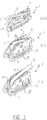
- FIGS 1 , 2 and 3 show a connecting device 1 in a preferred embodiment according to the invention arranged to be used in a windscreen wiper device of the "flat blade type" shown in figure 4 .
- a windscreen wiper device of the flat blade type is, for example, described in depth in European patent publication no. 1 568 559 , which is hereby incorporated by reference.
- Said windscreen wiper device is usually built up of an elastomeric wiper blade 15, comprising a central longitudinal groove 16, for example.
- a longitudinal strip 17 made of spring band steel, is fitted in said longitudinal groove.
- Said strip 17 forms a flexible carrier element for the wiper blade 15, as it were, which is thus biased in a curved position (the curvature in operative position being that of a windscreen to be wiped).
- Ends of the strip/wiper blade may be connected on either side of the windscreen wiper device to a connecting piece functioning as clamping members.
- the connecting pieces could be separate constructional elements, which may be form-locked ("positive locking" or “having a positive fit") or force-locked to the ends of the strip/wiper blade.
- said connecting pieces are in one piece with the strip made of spring band steel.
- the windscreen wiper device is furthermore built up of the connecting device 1 of plastic material for a hook-shaped oscillating arm 2.
- the connecting device 1 may also be made of metal, such as steel or aluminum.
- said connecting device 1 consists of a first part 3 and a second part 4 interconnected through a snapping operation.
- said first and second parts 3,4 are preferably detachably interconnected by snapping, that is clipping said second part 4 onto said first part 3.
- Said first part 3 of said connecting device 1 acts as a base part, wherein said first part 3 is preferably fixedly connected to the longitudinal strip(s) through a welding, brazing ("soldering"), gluing or clamping operation.
- said first part 3 is clamped onto the flexible material of the wiper blade, particularly in case the latter is equipped with a central longitudinal groove for the carrier element.
- Said second part 4 acts as a joint part interposed between said first part 3 and said oscillating arm 2. As depicted in figures 1 and 3 , said second part 4 is entirely positioned inside said first part 3.
- Said second part 4 has a U-shaped cross-section having legs 5 and a base 6 between them ( figure 2a ).
- said second part 4 comprises two protuberances 7 extending laterally outwardly on either leg 5 of said second part 4, wherein said protuberances 7 pivotally engage into correspondingly shaped recesses 8 of said first part 3 ( figures 1b and 1c , as well as figures 3b and 3c ).
- Said protuberances 7 are preferably cylindrical in shape.
- the oscillating arm 2 is pivotally connected to said connecting device 1 about a pivot axis near one end, as will be described hereunder.
- said oscillating arm 2 includes two parallel longitudinal arm sections 9,10 connected to each other by means of a curved intermediate section 11, wherein the sections 9, 10, 11 are in one piece.
- Figure 1 shows stepwise how a unit consisting of the connecting device 1 and the wiper blade is mounted onto the hook-shaped oscillating arm 2.
- the oscillating arm 2 is positioned in its service position, wherein the oscillating arm 2 is in an upright position relative to a windscreen to be wiped, so that the wiper blade can be repaired or replaced ( figure 1a ).
- the second part 4 is pivoted relative to the first part 3 of the connecting device 1, wherein a front part or nose 12 of the second part 4 is directed in an upward direction relative to the first part 3.
- the legs 5 of the U-shaped cross-section of the second part 4 are able to bend laterally outwardly, under plastic or elastic deformation, so that the second part 4(and the first part 3 and the wiper blade connected thereto) can be easily slid onto the oscillating arm 2 ( figures 1a and 1b ).
- the oscillating arm 2 is positioned in its wiping position, wherein the wiper blade is able to carry out its oscillatory movement along a windscreen to be wiped.
- the second part 4 is pivoted back relative to the first part 3 of the connecting device 1, wherein the front part or nose 12 of the second part 4 is directed in a downward direction relative to the first part 3.
- the legs 5 of the U-shaped cross-section of the second part 4 face adjacent side walls 13 of the first part 3 of the connecting device 1 ( figure 1c ) Said side walls 13 of said first part 3 block a lateral outward bending of said legs 5 of said U-shaped cross-section in order to retain said oscillating arm 2 onto said second part 4.
- said legs 5 of said U-shaped cross-section each comprise a laterally inwardly extending protrusion 14 to block a longitudinal movement of said connecting device 1 (and the wiper blade attached thereto) away from said oscillating arm 2 in said wiping position.
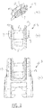
- Figure 2 shows the second part 4 of the connecting device 1 of figure 1 in a perspective, schematic view (a) and in a side view (b), as well as a side view of the first part 3 of the connecting device of figure 1(c) .
- Figures 3a, 3b and 3c are a perspective, schematic view of the first part 3 and the second part 4 of the connecting device 1 of figure 1 , assembled together, in a neutral position (a), in a service position (b) and in a wiping position (c), but without the oscillating arm 2.
- Figures 3b and 3c correspond to figures 1b and 1c , respectively, wherein corresponding parts have been designated with the same reference numerals.
- a spoiler is furthermore present being made in one piece with said wiper blade 2.
Landscapes
- Engineering & Computer Science (AREA)
- Mechanical Engineering (AREA)
- Pivots And Pivotal Connections (AREA)
- Transmission Devices (AREA)
Claims (12)
- Dispositif de balai d'essuie-glace du type « à lame plate » comprenant un élément porteur allongé élastique, ainsi qu'une lame de balai allongée, réalisée dans un matériau flexible, qui peut être placée en butée contre un pare-brise à essuyer, laquelle lame de balai comprend au moins une rainure longitudinale, rainure dans laquelle est disposée une bande longitudinale de l'élément porteur, lequel dispositif de balai d'essuie-glace comprend un dispositif de connexion (1) d'un bras oscillant (2) qui comprend deux sections de bras longitudinales (9, 10) connectées l'une à l'autre au moyen d'une section intermédiaire incurvée (11), dans lequel ledit bras oscillant (2) peut être connecté de manière pivotante audit dispositif de connexion (1) autour d'un axe de pivot, caractérisé en ce que ledit dispositif de connexion (1) comprend une première partie (3) et une seconde partie (4), ladite seconde partie (4) présentant une section transversale sensiblement au moins en forme de U avec une base (6) et des jambes élastiques (5), dans lequel ladite seconde partie (4) est connectée de manière pivotante à ladite première partie (3) autour dudit axe de pivot, entre une première position, dans laquelle lesdites jambes (5) de ladite section transversale en forme de U sont bloquées par ladite première partie (3) afin de fléchir latéralement vers l'extérieur de manière à retenir ladite seconde partie (4) sur ledit bras oscillant (2), et une seconde position dans laquelle lesdites jambes (5) de ladite section transversale en forme de U ont la possibilité de fléchir latéralement vers l'extérieur afin de libérer ladite seconde partie (4) dudit bras oscillant (2), dans lequel chacune desdites jambes (5) de ladite section transversale en forme de U, comprend une saillie qui s'étend latéralement vers l'intérieur (14) afin de bloquer un déplacement longitudinal dudit dispositif de connexion (1) en s'éloignant dudit bras oscillant (2) dans ladite première position.
- Dispositif de balai d'essuie-glace selon la revendication 1, dans lequel, dans ladite première position, lesdites jambes (5) de ladite section transversale en forme de U, font face à des parois latérales respectives (13) de ladite première partie (3), et dans lequel lesdites parois latérales (13) de ladite première partie (3), bloquent une flexion latérale vers l'extérieur desdites jambes (5) de ladite section transversale en forme de U, afin de retenir ladite seconde partie (4) sur ledit bras oscillant (2).
- Dispositif de balai d'essuie-glace selon la revendication 1 ou 2, dans lequel, dans ladite première position, ladite base (6) de ladite section transversale en forme de U, fait un angle aigu avec la lame de balai.
- Dispositif de balai d'essuie-glace selon l'une quelconque des revendications 1 à 3, dans lequel, dans ladite première position, une partie avant (12) de ladite seconde partie (4) fait face à un pare-brise à essuyer.
- Dispositif de balai d'essuie-glace selon l'une quelconque des revendications 1 à 4, dans lequel, dans ladite seconde position, ladite base (6) de ladite section transversale en forme de U, fait un angle aigu avec la lame de balai (2).
- Dispositif de balai d'essuie-glace selon l'une quelconque des revendications 1 à 5, dans lequel, dans ladite seconde position, une partie avant (12) de ladite seconde partie (4) fait face en s'éloignant d'un pare-brise à essuyer.
- Dispositif de balai d'essuie-glace selon l'une quelconque des revendications 1 à 6, dans lequel ladite seconde partie (4) est positionnée à l'intérieur de ladite première partie (3) à l'emplacement de leur interconnexion.
- Dispositif de balai d'essuie-glace selon l'une quelconque des revendications 1 à 7, dans lequel ladite seconde partie (4) comprend deux protubérances (7) qui s'étendent vers l'extérieur sur les deux côtés de ladite seconde partie (4), et dans lequel lesdites protubérances (7) viennent en prise de manière pivotante dans des renfoncements de forme correspondante (8) de ladite première partie (3).
- Dispositif de balai d'essuie-glace selon la revendication 8, dans lequel lesdites protubérances (7) présentent une forme cylindrique.
- Dispositif de balai d'essuie-glace selon l'une quelconque des revendications 1 à 9, dans lequel ladite première partie (3) est connectée à ladite bande.
- Dispositif de balai d'essuie-glace selon l'une quelconque des revendications 1 à 10, dans lequel ladite première partie (3) est connectée au matériau flexible de ladite lame de balai.
- Dispositif de balai d'essuie-glace selon l'une quelconque des revendications 1 à 11, dans lequel ladite première partie (3) et ladite seconde partie (4) sont interconnectés par une action d'encliquetage.
Applications Claiming Priority (1)
| Application Number | Priority Date | Filing Date | Title |
|---|---|---|---|
| PCT/EP2017/062918 WO2018219427A1 (fr) | 2017-05-29 | 2017-05-29 | Dispositif d'essuie-glace |
Publications (2)
| Publication Number | Publication Date |
|---|---|
| EP3630557A1 EP3630557A1 (fr) | 2020-04-08 |
| EP3630557B1 true EP3630557B1 (fr) | 2021-09-08 |
Family
ID=58800823
Family Applications (1)
| Application Number | Title | Priority Date | Filing Date |
|---|---|---|---|
| EP17726616.0A Active EP3630557B1 (fr) | 2017-05-29 | 2017-05-29 | Dispositif d'essuie-glace |
Country Status (6)
| Country | Link |
|---|---|
| US (1) | US20200108800A1 (fr) |
| EP (1) | EP3630557B1 (fr) |
| KR (1) | KR20200059189A (fr) |
| CN (1) | CN110678365A (fr) |
| MX (1) | MX2019014124A (fr) |
| WO (1) | WO2018219427A1 (fr) |
Family Cites Families (9)
| Publication number | Priority date | Publication date | Assignee | Title |
|---|---|---|---|---|
| IT1144856B (it) * | 1981-05-29 | 1986-10-29 | Arman Spa | Dispositivo per la connessione di una spatola tergicristallo ad un braccio di tergicristallo |
| DE29718379U1 (de) * | 1997-10-16 | 1998-01-02 | Robert Bosch Gmbh, 70469 Stuttgart | Scheibenwischer |
| US6161249A (en) * | 1999-01-27 | 2000-12-19 | Rally Manufacturing, Inc. | Windshield wiper frame and connector assembly |
| FR2866298B1 (fr) * | 2004-02-13 | 2007-04-13 | Valeo Systemes Dessuyage | Element de liaison de balai d'essuie-glace comportant un logement creux ouvert vers le haut |
| FR2902394B1 (fr) * | 2006-06-14 | 2009-02-20 | Valeo Systemes Dessuyage | Dispositif de fixation d'un balai d'essuie-glace sur un bras |
| DE212009000236U1 (de) * | 2009-09-01 | 2012-05-16 | Federal-Mogul S.A. | Scheibenwischervorrichtung |
| WO2011144244A1 (fr) * | 2010-05-20 | 2011-11-24 | Federal-Mogul S.A. | Dispositif d'essuie-glace |
| WO2012103944A1 (fr) * | 2011-02-02 | 2012-08-09 | Federal-Mogul S.A. | Dispositif d'essuie-glace |
| US9387829B2 (en) * | 2013-12-13 | 2016-07-12 | Xiamen Fuke Car Accessories Co., Ltd. | Windshield wiper connector |
-
2017
- 2017-05-29 US US16/617,568 patent/US20200108800A1/en not_active Abandoned
- 2017-05-29 WO PCT/EP2017/062918 patent/WO2018219427A1/fr not_active Ceased
- 2017-05-29 CN CN201780091381.0A patent/CN110678365A/zh active Pending
- 2017-05-29 KR KR1020197034678A patent/KR20200059189A/ko not_active Ceased
- 2017-05-29 MX MX2019014124A patent/MX2019014124A/es unknown
- 2017-05-29 EP EP17726616.0A patent/EP3630557B1/fr active Active
Also Published As
| Publication number | Publication date |
|---|---|
| CN110678365A (zh) | 2020-01-10 |
| KR20200059189A (ko) | 2020-05-28 |
| WO2018219427A1 (fr) | 2018-12-06 |
| EP3630557A1 (fr) | 2020-04-08 |
| US20200108800A1 (en) | 2020-04-09 |
| MX2019014124A (es) | 2020-07-29 |
Similar Documents
| Publication | Publication Date | Title |
|---|---|---|
| EP1849666B1 (fr) | Dispositif d'essuie-glace | |
| EP1312522B1 (fr) | Dispositif d'essuie-glace comprenant un élément support et un balai | |
| EP1359073B1 (fr) | Dispositif d'essuie-glace | |
| EP1854685B1 (fr) | Dispositif d'essuie-glace | |
| EP1876073B1 (fr) | Dispositif d'essuie-glace | |
| EP3164304B1 (fr) | Dispositif de balai d'essuie-glace | |
| EP1876074B1 (fr) | Dispositif d'essuie-glace | |
| EP3416858B1 (fr) | Dispositif d'essuie-glace | |
| EP2670637B1 (fr) | Dispositif d'essuie-glace | |
| EP1745997B1 (fr) | Dispositif d'essuie-glace | |
| EP1795406B1 (fr) | Dispositif d'essuie-glace | |
| WO2002090156A1 (fr) | Essuie-glace | |
| EP1745998B1 (fr) | Dispositif d'essuie-glace | |
| WO2011050836A1 (fr) | Dispositif essuie-glace | |
| EP3630557B1 (fr) | Dispositif d'essuie-glace | |
| EP3853083B1 (fr) | Dispositif d'essuie-glace | |
| WO2019034242A1 (fr) | Dispositif d'essuie-glace | |
| US20200406863A1 (en) | A windscreen wiper device | |
| US11453369B2 (en) | Windscreen wiper device | |
| EP3749553B1 (fr) | Dispositif de type essuie-glace | |
| WO2018233847A1 (fr) | Dispositif essuie-glace |
Legal Events
| Date | Code | Title | Description |
|---|---|---|---|
| STAA | Information on the status of an ep patent application or granted ep patent |
Free format text: STATUS: UNKNOWN |
|
| STAA | Information on the status of an ep patent application or granted ep patent |
Free format text: STATUS: THE INTERNATIONAL PUBLICATION HAS BEEN MADE |
|
| PUAI | Public reference made under article 153(3) epc to a published international application that has entered the european phase |
Free format text: ORIGINAL CODE: 0009012 |
|
| STAA | Information on the status of an ep patent application or granted ep patent |
Free format text: STATUS: REQUEST FOR EXAMINATION WAS MADE |
|
| 17P | Request for examination filed |
Effective date: 20191212 |
|
| AK | Designated contracting states |
Kind code of ref document: A1 Designated state(s): AL AT BE BG CH CY CZ DE DK EE ES FI FR GB GR HR HU IE IS IT LI LT LU LV MC MK MT NL NO PL PT RO RS SE SI SK SM TR |
|
| AX | Request for extension of the european patent |
Extension state: BA ME |
|
| DAV | Request for validation of the european patent (deleted) | ||
| DAX | Request for extension of the european patent (deleted) | ||
| STAA | Information on the status of an ep patent application or granted ep patent |
Free format text: STATUS: EXAMINATION IS IN PROGRESS |
|
| 17Q | First examination report despatched |
Effective date: 20201127 |
|
| GRAP | Despatch of communication of intention to grant a patent |
Free format text: ORIGINAL CODE: EPIDOSNIGR1 |
|
| STAA | Information on the status of an ep patent application or granted ep patent |
Free format text: STATUS: GRANT OF PATENT IS INTENDED |
|
| INTG | Intention to grant announced |
Effective date: 20210420 |
|
| GRAS | Grant fee paid |
Free format text: ORIGINAL CODE: EPIDOSNIGR3 |
|
| GRAA | (expected) grant |
Free format text: ORIGINAL CODE: 0009210 |
|
| STAA | Information on the status of an ep patent application or granted ep patent |
Free format text: STATUS: THE PATENT HAS BEEN GRANTED |
|
| AK | Designated contracting states |
Kind code of ref document: B1 Designated state(s): AL AT BE BG CH CY CZ DE DK EE ES FI FR GB GR HR HU IE IS IT LI LT LU LV MC MK MT NL NO PL PT RO RS SE SI SK SM TR |
|
| REG | Reference to a national code |
Ref country code: GB Ref legal event code: FG4D |
|
| REG | Reference to a national code |
Ref country code: AT Ref legal event code: REF Ref document number: 1428330 Country of ref document: AT Kind code of ref document: T Effective date: 20210915 Ref country code: CH Ref legal event code: EP |
|
| REG | Reference to a national code |
Ref country code: IE Ref legal event code: FG4D |
|
| REG | Reference to a national code |
Ref country code: DE Ref legal event code: R096 Ref document number: 602017045655 Country of ref document: DE |
|
| REG | Reference to a national code |
Ref country code: LT Ref legal event code: MG9D |
|
| REG | Reference to a national code |
Ref country code: NL Ref legal event code: MP Effective date: 20210908 |
|
| PG25 | Lapsed in a contracting state [announced via postgrant information from national office to epo] |
Ref country code: HR Free format text: LAPSE BECAUSE OF FAILURE TO SUBMIT A TRANSLATION OF THE DESCRIPTION OR TO PAY THE FEE WITHIN THE PRESCRIBED TIME-LIMIT Effective date: 20210908 Ref country code: RS Free format text: LAPSE BECAUSE OF FAILURE TO SUBMIT A TRANSLATION OF THE DESCRIPTION OR TO PAY THE FEE WITHIN THE PRESCRIBED TIME-LIMIT Effective date: 20210908 Ref country code: SE Free format text: LAPSE BECAUSE OF FAILURE TO SUBMIT A TRANSLATION OF THE DESCRIPTION OR TO PAY THE FEE WITHIN THE PRESCRIBED TIME-LIMIT Effective date: 20210908 Ref country code: FI Free format text: LAPSE BECAUSE OF FAILURE TO SUBMIT A TRANSLATION OF THE DESCRIPTION OR TO PAY THE FEE WITHIN THE PRESCRIBED TIME-LIMIT Effective date: 20210908 Ref country code: ES Free format text: LAPSE BECAUSE OF FAILURE TO SUBMIT A TRANSLATION OF THE DESCRIPTION OR TO PAY THE FEE WITHIN THE PRESCRIBED TIME-LIMIT Effective date: 20210908 Ref country code: NO Free format text: LAPSE BECAUSE OF FAILURE TO SUBMIT A TRANSLATION OF THE DESCRIPTION OR TO PAY THE FEE WITHIN THE PRESCRIBED TIME-LIMIT Effective date: 20211208 Ref country code: BG Free format text: LAPSE BECAUSE OF FAILURE TO SUBMIT A TRANSLATION OF THE DESCRIPTION OR TO PAY THE FEE WITHIN THE PRESCRIBED TIME-LIMIT Effective date: 20211208 Ref country code: LT Free format text: LAPSE BECAUSE OF FAILURE TO SUBMIT A TRANSLATION OF THE DESCRIPTION OR TO PAY THE FEE WITHIN THE PRESCRIBED TIME-LIMIT Effective date: 20210908 |
|
| REG | Reference to a national code |
Ref country code: AT Ref legal event code: MK05 Ref document number: 1428330 Country of ref document: AT Kind code of ref document: T Effective date: 20210908 |
|
| PG25 | Lapsed in a contracting state [announced via postgrant information from national office to epo] |
Ref country code: LV Free format text: LAPSE BECAUSE OF FAILURE TO SUBMIT A TRANSLATION OF THE DESCRIPTION OR TO PAY THE FEE WITHIN THE PRESCRIBED TIME-LIMIT Effective date: 20210908 Ref country code: GR Free format text: LAPSE BECAUSE OF FAILURE TO SUBMIT A TRANSLATION OF THE DESCRIPTION OR TO PAY THE FEE WITHIN THE PRESCRIBED TIME-LIMIT Effective date: 20211209 |
|
| PG25 | Lapsed in a contracting state [announced via postgrant information from national office to epo] |
Ref country code: AT Free format text: LAPSE BECAUSE OF FAILURE TO SUBMIT A TRANSLATION OF THE DESCRIPTION OR TO PAY THE FEE WITHIN THE PRESCRIBED TIME-LIMIT Effective date: 20210908 |
|
| PG25 | Lapsed in a contracting state [announced via postgrant information from national office to epo] |
Ref country code: IS Free format text: LAPSE BECAUSE OF FAILURE TO SUBMIT A TRANSLATION OF THE DESCRIPTION OR TO PAY THE FEE WITHIN THE PRESCRIBED TIME-LIMIT Effective date: 20220108 Ref country code: SM Free format text: LAPSE BECAUSE OF FAILURE TO SUBMIT A TRANSLATION OF THE DESCRIPTION OR TO PAY THE FEE WITHIN THE PRESCRIBED TIME-LIMIT Effective date: 20210908 Ref country code: SK Free format text: LAPSE BECAUSE OF FAILURE TO SUBMIT A TRANSLATION OF THE DESCRIPTION OR TO PAY THE FEE WITHIN THE PRESCRIBED TIME-LIMIT Effective date: 20210908 Ref country code: RO Free format text: LAPSE BECAUSE OF FAILURE TO SUBMIT A TRANSLATION OF THE DESCRIPTION OR TO PAY THE FEE WITHIN THE PRESCRIBED TIME-LIMIT Effective date: 20210908 Ref country code: PT Free format text: LAPSE BECAUSE OF FAILURE TO SUBMIT A TRANSLATION OF THE DESCRIPTION OR TO PAY THE FEE WITHIN THE PRESCRIBED TIME-LIMIT Effective date: 20220110 Ref country code: PL Free format text: LAPSE BECAUSE OF FAILURE TO SUBMIT A TRANSLATION OF THE DESCRIPTION OR TO PAY THE FEE WITHIN THE PRESCRIBED TIME-LIMIT Effective date: 20210908 Ref country code: NL Free format text: LAPSE BECAUSE OF FAILURE TO SUBMIT A TRANSLATION OF THE DESCRIPTION OR TO PAY THE FEE WITHIN THE PRESCRIBED TIME-LIMIT Effective date: 20210908 Ref country code: EE Free format text: LAPSE BECAUSE OF FAILURE TO SUBMIT A TRANSLATION OF THE DESCRIPTION OR TO PAY THE FEE WITHIN THE PRESCRIBED TIME-LIMIT Effective date: 20210908 Ref country code: CZ Free format text: LAPSE BECAUSE OF FAILURE TO SUBMIT A TRANSLATION OF THE DESCRIPTION OR TO PAY THE FEE WITHIN THE PRESCRIBED TIME-LIMIT Effective date: 20210908 Ref country code: AL Free format text: LAPSE BECAUSE OF FAILURE TO SUBMIT A TRANSLATION OF THE DESCRIPTION OR TO PAY THE FEE WITHIN THE PRESCRIBED TIME-LIMIT Effective date: 20210908 |
|
| REG | Reference to a national code |
Ref country code: DE Ref legal event code: R097 Ref document number: 602017045655 Country of ref document: DE |
|
| PLBE | No opposition filed within time limit |
Free format text: ORIGINAL CODE: 0009261 |
|
| STAA | Information on the status of an ep patent application or granted ep patent |
Free format text: STATUS: NO OPPOSITION FILED WITHIN TIME LIMIT |
|
| PG25 | Lapsed in a contracting state [announced via postgrant information from national office to epo] |
Ref country code: DK Free format text: LAPSE BECAUSE OF FAILURE TO SUBMIT A TRANSLATION OF THE DESCRIPTION OR TO PAY THE FEE WITHIN THE PRESCRIBED TIME-LIMIT Effective date: 20210908 |
|
| 26N | No opposition filed |
Effective date: 20220609 |
|
| PG25 | Lapsed in a contracting state [announced via postgrant information from national office to epo] |
Ref country code: SI Free format text: LAPSE BECAUSE OF FAILURE TO SUBMIT A TRANSLATION OF THE DESCRIPTION OR TO PAY THE FEE WITHIN THE PRESCRIBED TIME-LIMIT Effective date: 20210908 |
|
| REG | Reference to a national code |
Ref country code: CH Ref legal event code: PL |
|
| REG | Reference to a national code |
Ref country code: BE Ref legal event code: MM Effective date: 20220531 |
|
| GBPC | Gb: european patent ceased through non-payment of renewal fee |
Effective date: 20220529 |
|
| PG25 | Lapsed in a contracting state [announced via postgrant information from national office to epo] |
Ref country code: MC Free format text: LAPSE BECAUSE OF FAILURE TO SUBMIT A TRANSLATION OF THE DESCRIPTION OR TO PAY THE FEE WITHIN THE PRESCRIBED TIME-LIMIT Effective date: 20210908 Ref country code: LU Free format text: LAPSE BECAUSE OF NON-PAYMENT OF DUE FEES Effective date: 20220529 Ref country code: LI Free format text: LAPSE BECAUSE OF NON-PAYMENT OF DUE FEES Effective date: 20220531 Ref country code: IT Free format text: LAPSE BECAUSE OF FAILURE TO SUBMIT A TRANSLATION OF THE DESCRIPTION OR TO PAY THE FEE WITHIN THE PRESCRIBED TIME-LIMIT Effective date: 20210908 Ref country code: CH Free format text: LAPSE BECAUSE OF NON-PAYMENT OF DUE FEES Effective date: 20220531 |
|
| PG25 | Lapsed in a contracting state [announced via postgrant information from national office to epo] |
Ref country code: IE Free format text: LAPSE BECAUSE OF NON-PAYMENT OF DUE FEES Effective date: 20220529 Ref country code: FR Free format text: LAPSE BECAUSE OF NON-PAYMENT OF DUE FEES Effective date: 20220531 |
|
| PG25 | Lapsed in a contracting state [announced via postgrant information from national office to epo] |
Ref country code: GB Free format text: LAPSE BECAUSE OF NON-PAYMENT OF DUE FEES Effective date: 20220529 Ref country code: BE Free format text: LAPSE BECAUSE OF NON-PAYMENT OF DUE FEES Effective date: 20220531 |
|
| PG25 | Lapsed in a contracting state [announced via postgrant information from national office to epo] |
Ref country code: MK Free format text: LAPSE BECAUSE OF FAILURE TO SUBMIT A TRANSLATION OF THE DESCRIPTION OR TO PAY THE FEE WITHIN THE PRESCRIBED TIME-LIMIT Effective date: 20210908 Ref country code: CY Free format text: LAPSE BECAUSE OF FAILURE TO SUBMIT A TRANSLATION OF THE DESCRIPTION OR TO PAY THE FEE WITHIN THE PRESCRIBED TIME-LIMIT Effective date: 20210908 |
|
| PG25 | Lapsed in a contracting state [announced via postgrant information from national office to epo] |
Ref country code: HU Free format text: LAPSE BECAUSE OF FAILURE TO SUBMIT A TRANSLATION OF THE DESCRIPTION OR TO PAY THE FEE WITHIN THE PRESCRIBED TIME-LIMIT; INVALID AB INITIO Effective date: 20170529 |
|
| PG25 | Lapsed in a contracting state [announced via postgrant information from national office to epo] |
Ref country code: MT Free format text: LAPSE BECAUSE OF FAILURE TO SUBMIT A TRANSLATION OF THE DESCRIPTION OR TO PAY THE FEE WITHIN THE PRESCRIBED TIME-LIMIT Effective date: 20210908 |
|
| PGFP | Annual fee paid to national office [announced via postgrant information from national office to epo] |
Ref country code: DE Payment date: 20250529 Year of fee payment: 9 |
|
| PG25 | Lapsed in a contracting state [announced via postgrant information from national office to epo] |
Ref country code: TR Free format text: LAPSE BECAUSE OF FAILURE TO SUBMIT A TRANSLATION OF THE DESCRIPTION OR TO PAY THE FEE WITHIN THE PRESCRIBED TIME-LIMIT Effective date: 20210908 |