EP3630612B1 - Fliegender ausleger für mehrzweck-luftbetankungsflugzeuge - Google Patents
Fliegender ausleger für mehrzweck-luftbetankungsflugzeuge Download PDFInfo
- Publication number
- EP3630612B1 EP3630612B1 EP18732633.5A EP18732633A EP3630612B1 EP 3630612 B1 EP3630612 B1 EP 3630612B1 EP 18732633 A EP18732633 A EP 18732633A EP 3630612 B1 EP3630612 B1 EP 3630612B1
- Authority
- EP
- European Patent Office
- Prior art keywords
- boom mast
- flying boom
- aircraft
- cargo
- mast
- Prior art date
- Legal status (The legal status is an assumption and is not a legal conclusion. Google has not performed a legal analysis and makes no representation as to the accuracy of the status listed.)
- Active
Links
Images

Classifications
-
- B—PERFORMING OPERATIONS; TRANSPORTING
- B64—AIRCRAFT; AVIATION; COSMONAUTICS
- B64D—EQUIPMENT FOR FITTING IN OR TO AIRCRAFT; FLIGHT SUITS; PARACHUTES; ARRANGEMENT OR MOUNTING OF POWER PLANTS OR PROPULSION TRANSMISSIONS IN AIRCRAFT
- B64D39/00—Refuelling during flight
- B64D39/02—Means for paying-in or out hose
-
- B—PERFORMING OPERATIONS; TRANSPORTING
- B64—AIRCRAFT; AVIATION; COSMONAUTICS
- B64C—AEROPLANES; HELICOPTERS
- B64C1/00—Fuselages; Constructional features common to fuselages, wings, stabilising surfaces or the like
- B64C1/14—Windows; Doors; Hatch covers or access panels; Surrounding frame structures; Canopies; Windscreens accessories therefor, e.g. pressure sensors, water deflectors, hinges, seals, handles, latches, windscreen wipers
- B64C1/1407—Doors; surrounding frames
- B64C1/1415—Cargo doors, e.g. incorporating ramps
-
- B—PERFORMING OPERATIONS; TRANSPORTING
- B64—AIRCRAFT; AVIATION; COSMONAUTICS
- B64D—EQUIPMENT FOR FITTING IN OR TO AIRCRAFT; FLIGHT SUITS; PARACHUTES; ARRANGEMENT OR MOUNTING OF POWER PLANTS OR PROPULSION TRANSMISSIONS IN AIRCRAFT
- B64D39/00—Refuelling during flight
-
- B—PERFORMING OPERATIONS; TRANSPORTING
- B64—AIRCRAFT; AVIATION; COSMONAUTICS
- B64D—EQUIPMENT FOR FITTING IN OR TO AIRCRAFT; FLIGHT SUITS; PARACHUTES; ARRANGEMENT OR MOUNTING OF POWER PLANTS OR PROPULSION TRANSMISSIONS IN AIRCRAFT
- B64D39/00—Refuelling during flight
- B64D39/04—Adaptations of hose construction
-
- B—PERFORMING OPERATIONS; TRANSPORTING
- B64—AIRCRAFT; AVIATION; COSMONAUTICS
- B64D—EQUIPMENT FOR FITTING IN OR TO AIRCRAFT; FLIGHT SUITS; PARACHUTES; ARRANGEMENT OR MOUNTING OF POWER PLANTS OR PROPULSION TRANSMISSIONS IN AIRCRAFT
- B64D39/00—Refuelling during flight
- B64D39/06—Connecting hose to aircraft; Disconnecting hose therefrom
Definitions
- the disclosure relates generally to aerial refueling systems which include an operator-controlled flying boom mast.
- the flying boom mast is operatively associated with an aerial refueling aircraft that allows the aircraft to serve multiple mission roles other than refueling (e.g., as a troop and/or material transport aircraft).
- WO 02/24529 A1 describes roll on roll off airborne refueling systems, spraying systems, dry particulate diffusion systems, and fluid spray dispersal systems for use with aircraft having a flying boom mast system.
- C-130J-30 from Lockheed Martin, the same model exemplified in document WO 02/24529 A1 . Its content includes general characteristics of the C-130J-30 such as its dimensions, weights, defensive systems, technology improvements and performance compared to previous aircraft models and shows the general outline of a cargo department according to the prior art.
- Flying boom masts are commonly employed to transfer fuel from one aircraft (known as a “tanker”) to another aircraft (known as the "receiver') during flight.
- a “tanker” the aircraft
- the “receiver'” the aircraft
- military aircraft may be aerially refueled multiple times so as to allow substantially longer deployment periods on target stations and/or to increase aircraft range than their normal fuel load would permit
- the conventional flying boom system associated with an aerial tanker aircraft is generally comprised of three component parts: (1) a control station, (2) auxiliary systems and (3) a mast.
- the control station will usually have seats for the on-board flying boom operator responsible for the controllable maneuvering of the mast and the transfer of fuel to the receiver aircraft once connection between the receiver aircraft and the mast has occurred.
- the on-board auxiliary systems are typically comprised of several electronic control boxes, fuel pumps, actuators, sensors and the like. Normally such auxiliary components will be installed in several spaced locations within the tanker aircraft.
- the mast is usually anchored to the lower rear portion of the tanker aircraft's fuselage and will typically include multiple aerodynamic control surfaces installed on a nonanchored distal extremity of the mast to allow the on-board operator to maneuver the terminal end of the mast in the tanker aircraft's slipstream.
- the mast will also typically include a telescopic tube which is capable of being extended toward the receiver aircraft during an aerial refueling operation so as to allow the mast to reach and make connection to the receiver aircraft in order to transfer fuel during flight.
- the telescopic tube is therefore also capable of being retracted away from the receiver aircraft once the aerial refueling operation has been completed.
- Airborne tanker aircraft are typically heavy civilian commercial aircraft that have been converted to conduct airborne refueling missions.
- the conversion of civilian commercial aircraft to aerial tanker capabilities is desirable due to, among other reasons, the extremely large on-board fuel capacity of such aircraft resulting in a concomitant long range capability, an increased cargo capacity (e.g., so as to allow stowage of extra fuel tanks and thus increased fuel off-loading capabilities for in-flight refueling operations).
- the conversion of commercial aircraft as a basic platform for aerial refueling operations is also desirable due to the reduced cost of conversion since only relatively mission-specific military-grade equipment and systems need to be installed, such as self-protection systems, configurable cabin floor for multiple configurations, military communication systems and aerial refueling systems (e.g., the flying boom mast, under-wing pods and fuselage refueling units).
- mission-specific military-grade equipment and systems such as self-protection systems, configurable cabin floor for multiple configurations, military communication systems and aerial refueling systems (e.g., the flying boom mast, under-wing pods and fuselage refueling units).
- To remove and install such military-grade systems is not a simple endeavor and usually consumes several days or even weeks to complete.
- Such an approach can also be considered for certain types of aircraft that have a cargo door located in the rear portion of the fuselage.
- conventional cargo doors are divided in two sections, i.e., the ramp section and the door section.
- the ramp section usually can be used as an extension of the cargo floor and also improves the accessibility of the cargo compartment when the aircraft is on the ground.
- the door section closes the cargo compartment. Both such sections, when closed, need to ensure a minimum leakage of air from the interior cabin during flight. They also need to be fully opened on the ground in order to allow full access to the cargo compartment for loading/offloading operations or to quickly install any specific interior configuration such as those allowing for medical evacuation (Medevac), passenger seats, firefighting, troop transport operations and the like.
- Medevac medical evacuation
- passenger seats firefighting, troop transport operations and the like.
- the invention defines a cargo aircraft according to claim 1 and a method according to claim 5.
- the cargo aircraft is configurable for aerial refueling operations comprising: a fuselage which includes a forward cargo ramp and an aft cargo door hinged relative to one another at an aft portion of the fuselage so as to be moveable between opened and closed positions to respectively open and close a cargo space within the fuselage; a flying boom mast system having a flying boom mast operably associated with the aft portion of the fuselage and moveable between a stowed and deployed conditions relative to the aft portion of the fuselage, the flying boom mast being received by a tail cone housing when in the stowed position thereof; a fuel supply line connecting the flying boom mast with an on-board fuel supply of the aircraft so as to allow aerial refueling of a receiver aircraft when the flying boom mast is in the deployed condition thereof; and an actuator assembly positioned at an aft end of the aircraft for reciprocally moving the flying boom mast between re
- a vision system operatively installed in the cargo ramp or the cargo door may be provided so as to allow an operator within the aircraft to visually control the flying boom mast during aerial refueling.
- the flying boom mast system may be provided with a winch assembly and a flexible tether cable connected to the flying boom mast, wherein operation of the winch assembly causes the flexible tether cable to move the flying boom mast between the stowed and deployed conditions thereof.
- the cargo ramp comprises a connection boss at an exterior location thereof, and wherein the flying boom mast is journally connected to the connection boss.
- the cargo ramp may include a vision system to allow an operator within the aircraft to visually control the flying boom mast during aerial refueling.
- a control console may be positioned within the cargo space of the aircraft to allow the operator to control operation of the flying boom mast during aerial refueling (e.g., with visual input being provided by the vision system).
- the cargo door comprises a connection boss such that the flying boom mast is journally connected to the connection boss.
- the vision system may be provided operatively with the cargo door.
- the piston member may be operable by any suitable motive system, e.g., electrical, hydraulic and/or pneumatic drive systems.
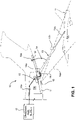
- FIG. 1 depicts a first example not claimed of a cargo (refueling) aircraft 10 provided with a rear cargo door access having oppositely hinged forward cargo ramp 11 and aft cargo door 12.
- a flying boom mast 13 is journally attached by a journal connection assembly 14a to a support boss 14 rigidly associated with the cargo ramp 11.
- the flying boom mast 13 maybe provided with a distal telescopically extendible portion 13a for connection to the receiving aircraft RA during a refueling operation and control surfaces 13b to allow an operator located, for example, in the flight deck (not shown) to control the flying boom mast 13 through the control rack 15 located inside the cargo space 10a of the aircraft 10.
- a vision system 16 having a vision field 16a is also provided on the cargo door 11 so as to allow the operator to visually monitor the receiving aircraft RA and the relative location of the distal end of the telescopically extendible portion 13a of the flying boom mast 13 so that connection can be made between the receiving aircraft RA and the mast 13 during refueling operations (e.g., by controllably moving the control surfaces 13b therefor at the control console that may be located in the flight deck through the control rack 15).
- fuel may be introduced by the operator to discharge fuel from the cargo (refueling) aircraft 10 to the receiving aircraft RA via a fuel line 17a fluid connected to an on-board fuel supply 17 of the cargo (refueling) aircraft 10.
- the flying boom mast 13 may be deployed between its operative refueling positions whereby the distal end therefor trails the aircraft 10 as shown in FIG. 1 and retrieved from such operative position so as to be stowed during periods of nonuse adjacent to the cargo door 12 by means of a flexible tether cable 18.
- the distal end of the flexible tether cable 18 is connected to the boom mast 13 while a proximal end of the cable 18 is connected to a winch system 18a positioned on an interior portion of the cargo door 12.
- the system comprising the flying boom mast 13, control rack 15 and tether cable 18 as depicted in FIG. 1 may be provided as a removable kit whereby all or some of such components may be readily removed from and reinstalled onto the aircraft 10 when the operator desires to convert the aircraft 10 from a cargo-carrying mission to an aerial refueling mission.
- the boom mast 13 and its associated operative components maybe removed physically from its journalled connected to the boss 14 on the exterior side of the cargo ramp 11 so that the latter may be hingedly moved between its closed condition to an opened condition to allow access to the cargo compartment 10a.
- the control rack 15 and associated fuel lines may be removed from or simply relocated within the aircraft 10 for future use.
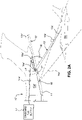
- FIGS. 2A and 2B An alternative example not claimed of a cargo aircraft 10' provided with a cargo ramp 11' and a cargo door 12' is depicted in FIGS. 2A and 2B .
- the structures that have been described previously with respect to the example of FIG. 1 that are similarly represented in the example of FIGS. 2A and 2B are denoted by the same reference numeral but with a prime designation (') for the latter.
- ' prime designation
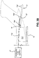
- the boom mast 13' does not necessarily require removal from the cargo door 12' in order to allow the cargo door 12' and cargo ramp 11' to be opened thereby gaining access to the cargo space 10a' within the aircraft 10' and thereby permit cargo/troop ingress egress while the aircraft is on the ground.
- FIG. 2B Such a state is shown in FIG. 2B .
- the cargo ramp 11' and cargo door 12' may be closed to allow the boom mast 13' to be operably moved between a stowed condition (shown in dashed line in FIG. 2A ) and a deployed condition (shown in solid line in FIG. 2A ) by means of an operator at a control station (not shown in FIGS. 2A and 2B , but which could be located, for example, in the flight deck) within the interior of the aircraft 10' whereby aerial refueling of a receiving aircraft RA may occur.
- a control station not shown in FIGS. 2A and 2B , but which could be located, for example, in the flight deck
- FIGS. 2A and 2B allow the aircraft 10' to function for both cargo/troop transport missions as well as aerial refueling missions without necessarily removing the boom mast 13' and its associated components.
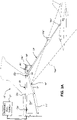
- FIGS. 3A and 3B An embodiment of a cargo aircraft 10" provided with a cargo ramp 11" and a cargo door 12" is depicted in FIGS. 3A and 3B .
- the structures that have been described previously with respect to the example of FIG. 1 that are similarly represented in the embodiment of FIGS. 3A and 3B are denoted by the same reference numeral but with a double-prime designation (") for the latter.
- FIGS. 3A and 3B differs principally from the example depicted in FIG. 1 by providing a tail cone housing 20 for the boom mast 13" when the latter is in the stowed condition as shown in FIG. 3B .
- FIGS. 3A and 3B also includes an actuator assembly 22 positioned at the aft end of the aircraft 10" which is comprised of a tubular receiver 22a having a reciprocally moveable piston member 22b therewithin.
- the piston member 22b may be operable between a retracted position as shown in FIG. 3B and an extended position as shown in FIG. 3A by any suitable motive system, e.g., electrical, pneumatic and/or hydraulic motive systems.
- a proximal end of the boom mast 13" is therefore journally connected to the piston member 22b so as to be moved thereby between its stowed condition ( FIG. 3B ) and its deployed condition ( FIG.
- the tail cone housing 20 will contain the tether cable 18" and winch assembly 18a" so as to assist in movement of the mast 13" between such retracted and extended positions.
- the boom mast 13" is slideably received within a journally mounted tubular guide member 24 operatively housed within the tail cone housing 20 so as to allow the mast 13" to be moved by an operator at a control station (not shown in FIGS. 3A and 3B , which could, for example, be located in the flight deck) controllably operating the boom mast mechanisms and positioning relative to the receiving aircraft RA.
- the fuel line 17a" must of course be capable of being extended/retracted with the deployment/stowage of the boom mast 13", e.g., by providing a reel and hose assembly (not shown) located within the cargo space 10a" or some other convenient location within the aircraft 10".
- the fuel line 17a" could also be connected to the actuator assembly 22 through a rigid or flexible coupling connection, in such a way that the transferred fuel flows through the actuator assembly 22 to reach the boom mast 13" and be transferred to the receiver aircraft RA.
- FIGS. 3A and 3B like the example depicted in FIGS. 2A and 2B , does not necessarily require removal from the cargo ramp 11" and/or cargo door 12' in order to allow the cargo door 12' and cargo ramp 11' to be opened thereby gaining access to the cargo space 10a' within the aircraft 10' and thereby permit cargo/troop ingress egress while the aircraft is on the ground (e.g.. as shown by FIG. 33).
- the embodiment depicted in FIGS. 3A and 3B allows the aircraft 10" to function for both cargo/troop transport missions as well as aerial refueling missions without necessarily removing the boom mast 13' and its associated components from the aircraft 10'.
Landscapes
- Engineering & Computer Science (AREA)
- Aviation & Aerospace Engineering (AREA)
- Mechanical Engineering (AREA)
- Forklifts And Lifting Vehicles (AREA)
- Aiming, Guidance, Guns With A Light Source, Armor, Camouflage, And Targets (AREA)
Claims (6)
- Frachtflugzeug (10"), welches für Luftbetankungsvorgänge eingerichtet werden kann, aufweisend:einen Rumpf, welcher eine vordere Laderampe (11") und eine hintere Ladeluke (12") aufweist, welche an einem hinteren Abschnitt des Rumpfes derart einander gegenüber scharnierbeweglich angeordnet sind, dass sie zwischen geöffneten und geschlossenen Positionen bewegt werden können, um einen Laderaum (10a") innerhalb des Rumpfes zu öffnen beziehungsweise zu schließen;ein Heckkonusgehäuse (20);ein Flugauslegermastsystem aufweisend einen Flugauslegermast (13"), welcher mit dem hinteren Abschnitt des Rumpfes wirkverbunden ist und zwischen einem eingeladenen Zustand und einem Einsatzzustand in Bezug auf den hinteren Abschnitt des Rumpfes bewegt werden kann, wobei der Flugauslegermast (13"), wenn er sich in seinem eingeladenen Zustand befindet, im Heckkonusgehäuse (20) aufgenommen ist;eine Treibstoffversorgungsleitung (17a"), welche den Flugauslegermast (13") mit einer Bordtreibstoffversorgung (17") des Flugzeugs (10") verbindet, um ein Luftbetanken eines Empfängerflugzeugs zu ermöglichen, wenn sich der Flugauslegermast (13") in seinem Einsatzzustand befindet; undeine Betätigungsbaugruppe (22), welche zum Bewegen des Flugauslegermastes (13") zwischen einer eingefahrenen Position und einer ausgefahrenen Position in Bezug auf das Heckkonusgehäuse (20) an einem hinteren Ende des Flugzeugs (10") angeordnet ist, wobei die Betätigungsbaugruppe (22) eine rohrförmige Aufnahme (22a) zum Aufnehmen eines Abschnitts des Flugauslegermastes, wenn dieser in seiner eingefahrenen Position angeordnet ist, und ein Kolbenelement (22b), welches beweglich mit einem näheren Ende des Flugauslegermastes (13") verbunden ist, aufweist, um den Flugauslegermast (13") zwischen der eingefahrenen und der ausgefahrenen Position zu bewegen.
- Frachtflugzeug (10") nach Anspruch 1, ferner aufweisend ein visuelles System (16"), welches in der Laderampe (11") oder der Ladeluke (12") derart betriebsfähig eingebaut ist, dass es einem Bediener im Inneren des Flugzeugs (10") ermöglicht, den Flugauslegermast (13") während des Luftbetankens visuell zu kontrollieren.
- Frachtflugzeug (10") nach Anspruch 1, wobei das Kolbenelement (22b) durch elektrische, hydraulische und/oder pneumatische Antriebssysteme betrieben werden kann.
- Frachtflugzeug (10") nach Anspruch 1, wobei das Flugauslegermastsystem eine Windenbaugruppe (18a") aufweist, welche innerhalb des Heckkonusgehäuses (20) untergebracht ist, und ein flexibles Haltekabel (18"), welches mit dem Flugauslegermasten (13") verbunden ist, wobei der Betrieb der Windenbaugruppe (18a") bewirkt, dass das flexible Haltekabel (18") den Flugauslegermast (13") zwischen dem eingeladenen und dem Einsatzzustand desselben bewegt, wenn sich der Auslegermast (13") in der ausgefahrenen Position in Bezug auf die Betätigungsbaugruppe (22) befindet.
- Verfahren zum Bereitstellen einer Luftbetankungstauglichkeit für ein Frachtflugzeug (10"), welches einen Rumpf aufweist, der eine vordere Laderampe (11") und eine hintere Ladeluke (12") aufweist, welche an einem hinteren Abschnitt des Rumpfes derart einander gegenüber scharnierbeweglich angeordnet sind, dass sie zwischen geöffneten und geschlossenen Positionen bewegt werden können, um einen Laderaum (10a") im Inneren des Rumpfes zu öffnen beziehungsweise zu schließen, wobei das Verfahren umfasst:(a) betriebsfähiges Bereitstellen eines Flugauslegermastsystems durch Anbringen eines Flugauslegermastes (13") am hinteren Abschnitt des Rumpfes, indem der Flugauslegermast (13") in Bezug auf ein Heckkonusgehäuse (20), welches mit dem Rumpf assoziiert ist, beweglich angebracht wird, so dass der Flugauslegermast (13") zwischen einem eingeladenen Zustand und einem Einsatzzustand in Bezug auf den hinteren Abschnitt des Rumpfes bewegt werden kann;(b) Fluidverbinden des Flugauslegermastes (13") und einer Bordtreibstoffversorgung (17") des Flugzeugs mit einer Treibstoffleitung (17a"), um ein Luftbetanken eines Empfängerflugzeugs zu ermöglichen, wenn sich der Flugauslegermast (13") in seinem Einsatzzustand befindet; und(c) betriebsfähiges Bereitstellen des hinteren Abschnitt des Rumpfes mit einer Betätigungsbaugruppe (22), um eine Bewegung des Flugauslegermastes zwischen einer eingefahrenen Position und einer ausgefahrenen Position in Bezug auf das Heckkonusgehäuse (20) zu ermöglichen, wobei die Betätigungsbaugruppe (22) aufweisend eine rohrförmige Aufnahme (22a) zum Aufnehmen eines Abschnitts des Flugauslegermastes, wenn dieser in seiner eingefahrenen Position angeordnet ist, und ein Kolbenelement (22b), welches beweglich mit einem näheren Ende des Flugauslegermastes (13") verbunden ist, bereitgestellt wird, um den Flugauslegermast (13") zwischen der eingefahrenen Position und der ausgefahrenen Position desselben zu bewegen.
- Verfahren nach Anspruch 5, wobei Schritt (a) ein Verbinden eines flexiblen Haltekabels (18") zwischen dem Flugauslegermast (13") und einer Windenbaugruppe (18a") umfasst, um eine Bewegung des Flugauslegermastes (13") zwischen dem eingeladenen Zustand und dem Einsatzzustand desselben zu ermöglichen.
Applications Claiming Priority (2)
| Application Number | Priority Date | Filing Date | Title |
|---|---|---|---|
| US201762514230P | 2017-06-02 | 2017-06-02 | |
| PCT/BR2018/000029 WO2018218321A1 (en) | 2017-06-02 | 2018-05-30 | Flying boom mast for multi-purpose aerial refueling aircraft |
Publications (2)
| Publication Number | Publication Date |
|---|---|
| EP3630612A1 EP3630612A1 (de) | 2020-04-08 |
| EP3630612B1 true EP3630612B1 (de) | 2022-08-17 |
Family
ID=62684550
Family Applications (1)
| Application Number | Title | Priority Date | Filing Date |
|---|---|---|---|
| EP18732633.5A Active EP3630612B1 (de) | 2017-06-02 | 2018-05-30 | Fliegender ausleger für mehrzweck-luftbetankungsflugzeuge |
Country Status (5)
| Country | Link |
|---|---|
| US (1) | US11148825B2 (de) |
| EP (1) | EP3630612B1 (de) |
| CN (1) | CN111032512B (de) |
| ES (1) | ES2933624T3 (de) |
| WO (1) | WO2018218321A1 (de) |
Families Citing this family (4)
| Publication number | Priority date | Publication date | Assignee | Title |
|---|---|---|---|---|
| EP3838753B1 (de) | 2019-12-17 | 2022-03-16 | LEONARDO S.p.A. | Wandelflugzeug |
| US12024311B1 (en) * | 2022-08-15 | 2024-07-02 | United States Of America As Represented By The Secretary Of The Air Force | Remotely operable cover for aircraft refueling boom |
| CN115817831A (zh) * | 2022-12-26 | 2023-03-21 | 中国航空工业集团公司西安飞机设计研究所 | 一种硬式双操纵主动空中加油装置及方法 |
| US12583584B2 (en) * | 2023-09-07 | 2026-03-24 | Jetzero, Inc. | Tanker aircraft for long-distance travel |
Citations (1)
| Publication number | Priority date | Publication date | Assignee | Title |
|---|---|---|---|---|
| EP0758971B1 (de) * | 1993-02-09 | 1998-12-30 | McDONNELL DOUGLAS CORPORATION | Rampensystem |
Family Cites Families (10)
| Publication number | Priority date | Publication date | Assignee | Title |
|---|---|---|---|---|
| US3055620A (en) * | 1959-08-10 | 1962-09-25 | Boeing Co | Cargo airplanes |
| US4097009A (en) * | 1977-04-27 | 1978-06-27 | The Boeing Company | Aircraft ramp door |
| US4088288A (en) * | 1977-04-27 | 1978-05-09 | The Boeing Company | Aircraft ramp assembly |
| US4498648A (en) * | 1983-06-27 | 1985-02-12 | Lockheed Corporation | Cargo door assembly |
| US5241722A (en) * | 1991-01-31 | 1993-09-07 | Mcdonnell Douglas Corporation | Ramp system |
| US5253381A (en) * | 1991-01-31 | 1993-10-19 | Mcdonnell Douglas Corporation | Hinged cargo ramp |
| AU2001291570A1 (en) * | 2000-09-21 | 2002-04-02 | Richard Lawrence Ken Woodland | Roll on - roll off, portable aerial spraying, particulate dispersal, and refueling systems apparatus |
| US7147186B2 (en) * | 2004-11-18 | 2006-12-12 | The Boeing Company | Interoperable aerial refueling apparatus and methods |
| US9090354B2 (en) * | 2006-03-02 | 2015-07-28 | The Boeing Company | System and method for identifying a receiving aircraft during airborne fueling |
| EP2216247A4 (de) * | 2007-11-19 | 2013-08-14 | Eads Constr Aeronauticas Sa | Mit hubunterstützungsmitteln versehener einziehbarer betankungsschlauch |
-
2018
- 2018-05-30 CN CN201880036477.1A patent/CN111032512B/zh active Active
- 2018-05-30 ES ES18732633T patent/ES2933624T3/es active Active
- 2018-05-30 EP EP18732633.5A patent/EP3630612B1/de active Active
- 2018-05-30 WO PCT/BR2018/000029 patent/WO2018218321A1/en not_active Ceased
- 2018-05-31 US US15/994,032 patent/US11148825B2/en active Active
Patent Citations (1)
| Publication number | Priority date | Publication date | Assignee | Title |
|---|---|---|---|---|
| EP0758971B1 (de) * | 1993-02-09 | 1998-12-30 | McDONNELL DOUGLAS CORPORATION | Rampensystem |
Also Published As
| Publication number | Publication date |
|---|---|
| CN111032512A (zh) | 2020-04-17 |
| EP3630612A1 (de) | 2020-04-08 |
| US20180346141A1 (en) | 2018-12-06 |
| BR112019025491A2 (pt) | 2020-06-23 |
| US11148825B2 (en) | 2021-10-19 |
| CN111032512B (zh) | 2023-06-16 |
| WO2018218321A1 (en) | 2018-12-06 |
| ES2933624T3 (es) | 2023-02-10 |
Similar Documents
| Publication | Publication Date | Title |
|---|---|---|
| US7093798B2 (en) | Transformable airplane | |
| US5573206A (en) | Hose and drogue boom refueling system, for aircraft | |
| US11148825B2 (en) | Flying boom mast for multi-purpose aerial refueling aircraft | |
| US9180967B2 (en) | Configurable pod structure and store stowage and deployment system and method | |
| US11235851B2 (en) | Temporarily-installed aircraft observer door plug, chair, sonotube ejection and control system | |
| US9027879B1 (en) | Modular adaptive configured helicopter | |
| US10589859B2 (en) | Apparatus and method for aerial recovery of an unmanned aerial vehicle | |
| US20200377192A1 (en) | Aircraft based non-dedicated special mission pod mounting apparatus | |
| US6394392B1 (en) | Aircraft having multiple fuselages | |
| US6869042B2 (en) | System for airborne launch of an aircraft from a larger carrier aircraft | |
| US8302902B2 (en) | Method and apparatus for operating an aircraft landing system | |
| US10301004B2 (en) | Temporarily-installed aircraft observer door plug, chair, sonotube ejection and control system | |
| WO2002024529A1 (en) | Roll on - roll off, portable aerial spraying, particulate dispersal, and refueling systems apparatus | |
| EP2527256B1 (de) | Fangtrichterausfahrsystem für Luftbetankung | |
| EP1780123A2 (de) | Systeme und Verfahren zur Reduzierung von Belastungen durch Druckspitzen in Schläuchen, einschliesslich Flugzeugbetankungsschläuche | |
| EP3161405B1 (de) | Startsystem für verstaubaren effektor | |
| US8317136B2 (en) | Stabilized controllable drogue for aerial flight refueling | |
| BR112019025491B1 (pt) | Mastro de lança de voo para aeronave de reabastecimento aéreo de múltiplos propósitos | |
| GB2601781A (en) | Deflatable fuel tank | |
| US12179903B2 (en) | Aircraft-based modular door panel assembly |
Legal Events
| Date | Code | Title | Description |
|---|---|---|---|
| STAA | Information on the status of an ep patent application or granted ep patent |
Free format text: STATUS: UNKNOWN |
|
| STAA | Information on the status of an ep patent application or granted ep patent |
Free format text: STATUS: THE INTERNATIONAL PUBLICATION HAS BEEN MADE |
|
| PUAI | Public reference made under article 153(3) epc to a published international application that has entered the european phase |
Free format text: ORIGINAL CODE: 0009012 |
|
| STAA | Information on the status of an ep patent application or granted ep patent |
Free format text: STATUS: REQUEST FOR EXAMINATION WAS MADE |
|
| 17P | Request for examination filed |
Effective date: 20191129 |
|
| AK | Designated contracting states |
Kind code of ref document: A1 Designated state(s): AL AT BE BG CH CY CZ DE DK EE ES FI FR GB GR HR HU IE IS IT LI LT LU LV MC MK MT NL NO PL PT RO RS SE SI SK SM TR |
|
| AX | Request for extension of the european patent |
Extension state: BA ME |
|
| DAV | Request for validation of the european patent (deleted) | ||
| DAX | Request for extension of the european patent (deleted) | ||
| STAA | Information on the status of an ep patent application or granted ep patent |
Free format text: STATUS: EXAMINATION IS IN PROGRESS |
|
| 17Q | First examination report despatched |
Effective date: 20210310 |
|
| GRAP | Despatch of communication of intention to grant a patent |
Free format text: ORIGINAL CODE: EPIDOSNIGR1 |
|
| STAA | Information on the status of an ep patent application or granted ep patent |
Free format text: STATUS: GRANT OF PATENT IS INTENDED |
|
| INTG | Intention to grant announced |
Effective date: 20220422 |
|
| GRAS | Grant fee paid |
Free format text: ORIGINAL CODE: EPIDOSNIGR3 |
|
| GRAA | (expected) grant |
Free format text: ORIGINAL CODE: 0009210 |
|
| STAA | Information on the status of an ep patent application or granted ep patent |
Free format text: STATUS: THE PATENT HAS BEEN GRANTED |
|
| AK | Designated contracting states |
Kind code of ref document: B1 Designated state(s): AL AT BE BG CH CY CZ DE DK EE ES FI FR GB GR HR HU IE IS IT LI LT LU LV MC MK MT NL NO PL PT RO RS SE SI SK SM TR |
|
| REG | Reference to a national code |
Ref country code: CH Ref legal event code: EP |
|
| REG | Reference to a national code |
Ref country code: DE Ref legal event code: R096 Ref document number: 602018039403 Country of ref document: DE |
|
| REG | Reference to a national code |
Ref country code: IE Ref legal event code: FG4D |
|
| REG | Reference to a national code |
Ref country code: AT Ref legal event code: REF Ref document number: 1512026 Country of ref document: AT Kind code of ref document: T Effective date: 20220915 |
|
| REG | Reference to a national code |
Ref country code: NL Ref legal event code: MP Effective date: 20220817 |
|
| REG | Reference to a national code |
Ref country code: LT Ref legal event code: MG9D |
|
| PG25 | Lapsed in a contracting state [announced via postgrant information from national office to epo] |
Ref country code: SE Free format text: LAPSE BECAUSE OF FAILURE TO SUBMIT A TRANSLATION OF THE DESCRIPTION OR TO PAY THE FEE WITHIN THE PRESCRIBED TIME-LIMIT Effective date: 20220817 Ref country code: RS Free format text: LAPSE BECAUSE OF FAILURE TO SUBMIT A TRANSLATION OF THE DESCRIPTION OR TO PAY THE FEE WITHIN THE PRESCRIBED TIME-LIMIT Effective date: 20220817 Ref country code: PT Free format text: LAPSE BECAUSE OF FAILURE TO SUBMIT A TRANSLATION OF THE DESCRIPTION OR TO PAY THE FEE WITHIN THE PRESCRIBED TIME-LIMIT Effective date: 20221219 Ref country code: NO Free format text: LAPSE BECAUSE OF FAILURE TO SUBMIT A TRANSLATION OF THE DESCRIPTION OR TO PAY THE FEE WITHIN THE PRESCRIBED TIME-LIMIT Effective date: 20221117 Ref country code: NL Free format text: LAPSE BECAUSE OF FAILURE TO SUBMIT A TRANSLATION OF THE DESCRIPTION OR TO PAY THE FEE WITHIN THE PRESCRIBED TIME-LIMIT Effective date: 20220817 Ref country code: LV Free format text: LAPSE BECAUSE OF FAILURE TO SUBMIT A TRANSLATION OF THE DESCRIPTION OR TO PAY THE FEE WITHIN THE PRESCRIBED TIME-LIMIT Effective date: 20220817 Ref country code: LT Free format text: LAPSE BECAUSE OF FAILURE TO SUBMIT A TRANSLATION OF THE DESCRIPTION OR TO PAY THE FEE WITHIN THE PRESCRIBED TIME-LIMIT Effective date: 20220817 Ref country code: FI Free format text: LAPSE BECAUSE OF FAILURE TO SUBMIT A TRANSLATION OF THE DESCRIPTION OR TO PAY THE FEE WITHIN THE PRESCRIBED TIME-LIMIT Effective date: 20220817 |
|
| REG | Reference to a national code |
Ref country code: ES Ref legal event code: FG2A Ref document number: 2933624 Country of ref document: ES Kind code of ref document: T3 Effective date: 20230210 |
|
| REG | Reference to a national code |
Ref country code: AT Ref legal event code: MK05 Ref document number: 1512026 Country of ref document: AT Kind code of ref document: T Effective date: 20220817 |
|
| PG25 | Lapsed in a contracting state [announced via postgrant information from national office to epo] |
Ref country code: PL Free format text: LAPSE BECAUSE OF FAILURE TO SUBMIT A TRANSLATION OF THE DESCRIPTION OR TO PAY THE FEE WITHIN THE PRESCRIBED TIME-LIMIT Effective date: 20220817 Ref country code: IS Free format text: LAPSE BECAUSE OF FAILURE TO SUBMIT A TRANSLATION OF THE DESCRIPTION OR TO PAY THE FEE WITHIN THE PRESCRIBED TIME-LIMIT Effective date: 20221217 Ref country code: HR Free format text: LAPSE BECAUSE OF FAILURE TO SUBMIT A TRANSLATION OF THE DESCRIPTION OR TO PAY THE FEE WITHIN THE PRESCRIBED TIME-LIMIT Effective date: 20220817 Ref country code: GR Free format text: LAPSE BECAUSE OF FAILURE TO SUBMIT A TRANSLATION OF THE DESCRIPTION OR TO PAY THE FEE WITHIN THE PRESCRIBED TIME-LIMIT Effective date: 20221118 |
|
| PG25 | Lapsed in a contracting state [announced via postgrant information from national office to epo] |
Ref country code: SM Free format text: LAPSE BECAUSE OF FAILURE TO SUBMIT A TRANSLATION OF THE DESCRIPTION OR TO PAY THE FEE WITHIN THE PRESCRIBED TIME-LIMIT Effective date: 20220817 Ref country code: RO Free format text: LAPSE BECAUSE OF FAILURE TO SUBMIT A TRANSLATION OF THE DESCRIPTION OR TO PAY THE FEE WITHIN THE PRESCRIBED TIME-LIMIT Effective date: 20220817 Ref country code: DK Free format text: LAPSE BECAUSE OF FAILURE TO SUBMIT A TRANSLATION OF THE DESCRIPTION OR TO PAY THE FEE WITHIN THE PRESCRIBED TIME-LIMIT Effective date: 20220817 Ref country code: CZ Free format text: LAPSE BECAUSE OF FAILURE TO SUBMIT A TRANSLATION OF THE DESCRIPTION OR TO PAY THE FEE WITHIN THE PRESCRIBED TIME-LIMIT Effective date: 20220817 Ref country code: AT Free format text: LAPSE BECAUSE OF FAILURE TO SUBMIT A TRANSLATION OF THE DESCRIPTION OR TO PAY THE FEE WITHIN THE PRESCRIBED TIME-LIMIT Effective date: 20220817 |
|
| REG | Reference to a national code |
Ref country code: DE Ref legal event code: R097 Ref document number: 602018039403 Country of ref document: DE |
|
| PG25 | Lapsed in a contracting state [announced via postgrant information from national office to epo] |
Ref country code: SK Free format text: LAPSE BECAUSE OF FAILURE TO SUBMIT A TRANSLATION OF THE DESCRIPTION OR TO PAY THE FEE WITHIN THE PRESCRIBED TIME-LIMIT Effective date: 20220817 Ref country code: EE Free format text: LAPSE BECAUSE OF FAILURE TO SUBMIT A TRANSLATION OF THE DESCRIPTION OR TO PAY THE FEE WITHIN THE PRESCRIBED TIME-LIMIT Effective date: 20220817 |
|
| PLBE | No opposition filed within time limit |
Free format text: ORIGINAL CODE: 0009261 |
|
| STAA | Information on the status of an ep patent application or granted ep patent |
Free format text: STATUS: NO OPPOSITION FILED WITHIN TIME LIMIT |
|
| PG25 | Lapsed in a contracting state [announced via postgrant information from national office to epo] |
Ref country code: AL Free format text: LAPSE BECAUSE OF FAILURE TO SUBMIT A TRANSLATION OF THE DESCRIPTION OR TO PAY THE FEE WITHIN THE PRESCRIBED TIME-LIMIT Effective date: 20220817 |
|
| 26N | No opposition filed |
Effective date: 20230519 |
|
| PG25 | Lapsed in a contracting state [announced via postgrant information from national office to epo] |
Ref country code: SI Free format text: LAPSE BECAUSE OF FAILURE TO SUBMIT A TRANSLATION OF THE DESCRIPTION OR TO PAY THE FEE WITHIN THE PRESCRIBED TIME-LIMIT Effective date: 20220817 |
|
| REG | Reference to a national code |
Ref country code: CH Ref legal event code: PL |
|
| PG25 | Lapsed in a contracting state [announced via postgrant information from national office to epo] |
Ref country code: MC Free format text: LAPSE BECAUSE OF FAILURE TO SUBMIT A TRANSLATION OF THE DESCRIPTION OR TO PAY THE FEE WITHIN THE PRESCRIBED TIME-LIMIT Effective date: 20220817 |
|
| GBPC | Gb: european patent ceased through non-payment of renewal fee |
Effective date: 20230530 |
|
| REG | Reference to a national code |
Ref country code: BE Ref legal event code: MM Effective date: 20230531 |
|
| PG25 | Lapsed in a contracting state [announced via postgrant information from national office to epo] |
Ref country code: MC Free format text: LAPSE BECAUSE OF FAILURE TO SUBMIT A TRANSLATION OF THE DESCRIPTION OR TO PAY THE FEE WITHIN THE PRESCRIBED TIME-LIMIT Effective date: 20220817 Ref country code: LU Free format text: LAPSE BECAUSE OF NON-PAYMENT OF DUE FEES Effective date: 20230530 Ref country code: LI Free format text: LAPSE BECAUSE OF NON-PAYMENT OF DUE FEES Effective date: 20230531 Ref country code: CH Free format text: LAPSE BECAUSE OF NON-PAYMENT OF DUE FEES Effective date: 20230531 |
|
| REG | Reference to a national code |
Ref country code: IE Ref legal event code: MM4A |
|
| PG25 | Lapsed in a contracting state [announced via postgrant information from national office to epo] |
Ref country code: IE Free format text: LAPSE BECAUSE OF NON-PAYMENT OF DUE FEES Effective date: 20230530 |
|
| PG25 | Lapsed in a contracting state [announced via postgrant information from national office to epo] |
Ref country code: IE Free format text: LAPSE BECAUSE OF NON-PAYMENT OF DUE FEES Effective date: 20230530 Ref country code: GB Free format text: LAPSE BECAUSE OF NON-PAYMENT OF DUE FEES Effective date: 20230530 |
|
| PG25 | Lapsed in a contracting state [announced via postgrant information from national office to epo] |
Ref country code: IT Free format text: LAPSE BECAUSE OF FAILURE TO SUBMIT A TRANSLATION OF THE DESCRIPTION OR TO PAY THE FEE WITHIN THE PRESCRIBED TIME-LIMIT Effective date: 20220817 Ref country code: BE Free format text: LAPSE BECAUSE OF NON-PAYMENT OF DUE FEES Effective date: 20230531 |
|
| PG25 | Lapsed in a contracting state [announced via postgrant information from national office to epo] |
Ref country code: BG Free format text: LAPSE BECAUSE OF FAILURE TO SUBMIT A TRANSLATION OF THE DESCRIPTION OR TO PAY THE FEE WITHIN THE PRESCRIBED TIME-LIMIT Effective date: 20220817 |
|
| PG25 | Lapsed in a contracting state [announced via postgrant information from national office to epo] |
Ref country code: BG Free format text: LAPSE BECAUSE OF FAILURE TO SUBMIT A TRANSLATION OF THE DESCRIPTION OR TO PAY THE FEE WITHIN THE PRESCRIBED TIME-LIMIT Effective date: 20220817 |
|
| PGFP | Annual fee paid to national office [announced via postgrant information from national office to epo] |
Ref country code: DE Payment date: 20250528 Year of fee payment: 8 |
|
| PGFP | Annual fee paid to national office [announced via postgrant information from national office to epo] |
Ref country code: ES Payment date: 20250611 Year of fee payment: 8 |
|
| PGFP | Annual fee paid to national office [announced via postgrant information from national office to epo] |
Ref country code: FR Payment date: 20250526 Year of fee payment: 8 |
|
| PG25 | Lapsed in a contracting state [announced via postgrant information from national office to epo] |
Ref country code: CY Free format text: LAPSE BECAUSE OF FAILURE TO SUBMIT A TRANSLATION OF THE DESCRIPTION OR TO PAY THE FEE WITHIN THE PRESCRIBED TIME-LIMIT; INVALID AB INITIO Effective date: 20180530 |
|
| PG25 | Lapsed in a contracting state [announced via postgrant information from national office to epo] |
Ref country code: HU Free format text: LAPSE BECAUSE OF FAILURE TO SUBMIT A TRANSLATION OF THE DESCRIPTION OR TO PAY THE FEE WITHIN THE PRESCRIBED TIME-LIMIT; INVALID AB INITIO Effective date: 20180530 |
|
| PG25 | Lapsed in a contracting state [announced via postgrant information from national office to epo] |
Ref country code: TR Free format text: LAPSE BECAUSE OF FAILURE TO SUBMIT A TRANSLATION OF THE DESCRIPTION OR TO PAY THE FEE WITHIN THE PRESCRIBED TIME-LIMIT Effective date: 20220817 |