EP3631128B1 - Dispositif d'entraînement pour déverrouiller et verrouiller un verrou - Google Patents
Dispositif d'entraînement pour déverrouiller et verrouiller un verrou Download PDFInfo
- Publication number
- EP3631128B1 EP3631128B1 EP18739925.8A EP18739925A EP3631128B1 EP 3631128 B1 EP3631128 B1 EP 3631128B1 EP 18739925 A EP18739925 A EP 18739925A EP 3631128 B1 EP3631128 B1 EP 3631128B1
- Authority
- EP
- European Patent Office
- Prior art keywords
- electric energy
- energy source
- driving device
- driving motor
- housing
- Prior art date
- Legal status (The legal status is an assumption and is not a legal conclusion. Google has not performed a legal analysis and makes no representation as to the accuracy of the status listed.)
- Active
Links
Images





Classifications
-
- E—FIXED CONSTRUCTIONS
- E05—LOCKS; KEYS; WINDOW OR DOOR FITTINGS; SAFES
- E05B—LOCKS; ACCESSORIES THEREFOR; HANDCUFFS
- E05B47/00—Operating or controlling locks or other fastening devices by electric or magnetic means
- E05B47/0001—Operating or controlling locks or other fastening devices by electric or magnetic means with electric actuators; Constructional features thereof
- E05B47/0012—Operating or controlling locks or other fastening devices by electric or magnetic means with electric actuators; Constructional features thereof with rotary electromotors
-
- E—FIXED CONSTRUCTIONS
- E05—LOCKS; KEYS; WINDOW OR DOOR FITTINGS; SAFES
- E05B—LOCKS; ACCESSORIES THEREFOR; HANDCUFFS
- E05B47/00—Operating or controlling locks or other fastening devices by electric or magnetic means
- E05B47/06—Controlling mechanically-operated bolts by electro-magnetically-operated detents
- E05B47/0611—Cylinder locks with electromagnetic control
- E05B47/0615—Cylinder locks with electromagnetic control operated by handles, e.g. by knobs
-
- G—PHYSICS
- G07—CHECKING-DEVICES
- G07C—TIME OR ATTENDANCE REGISTERS; REGISTERING OR INDICATING THE WORKING OF MACHINES; GENERATING RANDOM NUMBERS; VOTING OR LOTTERY APPARATUS; ARRANGEMENTS, SYSTEMS OR APPARATUS FOR CHECKING NOT PROVIDED FOR ELSEWHERE
- G07C9/00—Individual registration on entry or exit
- G07C9/00174—Electronically operated locks; Circuits therefor; Nonmechanical keys therefor, e.g. passive or active electrical keys or other data carriers without mechanical keys
- G07C9/00182—Electronically operated locks; Circuits therefor; Nonmechanical keys therefor, e.g. passive or active electrical keys or other data carriers without mechanical keys operated with unidirectional data transmission between data carrier and locks
-
- E—FIXED CONSTRUCTIONS
- E05—LOCKS; KEYS; WINDOW OR DOOR FITTINGS; SAFES
- E05B—LOCKS; ACCESSORIES THEREFOR; HANDCUFFS
- E05B47/00—Operating or controlling locks or other fastening devices by electric or magnetic means
- E05B47/0001—Operating or controlling locks or other fastening devices by electric or magnetic means with electric actuators; Constructional features thereof
- E05B2047/0014—Constructional features of actuators or power transmissions therefor
- E05B2047/0018—Details of actuator transmissions
- E05B2047/002—Geared transmissions
-
- E—FIXED CONSTRUCTIONS
- E05—LOCKS; KEYS; WINDOW OR DOOR FITTINGS; SAFES
- E05B—LOCKS; ACCESSORIES THEREFOR; HANDCUFFS
- E05B47/00—Operating or controlling locks or other fastening devices by electric or magnetic means
- E05B2047/0048—Circuits, feeding, monitoring
- E05B2047/0057—Feeding
- E05B2047/0058—Feeding by batteries
-
- E—FIXED CONSTRUCTIONS
- E05—LOCKS; KEYS; WINDOW OR DOOR FITTINGS; SAFES
- E05B—LOCKS; ACCESSORIES THEREFOR; HANDCUFFS
- E05B47/00—Operating or controlling locks or other fastening devices by electric or magnetic means
- E05B2047/0048—Circuits, feeding, monitoring
- E05B2047/0067—Monitoring
-
- E—FIXED CONSTRUCTIONS
- E05—LOCKS; KEYS; WINDOW OR DOOR FITTINGS; SAFES
- E05B—LOCKS; ACCESSORIES THEREFOR; HANDCUFFS
- E05B47/00—Operating or controlling locks or other fastening devices by electric or magnetic means
- E05B2047/0091—Retrofittable electric locks, e.g. an electric module can be attached to an existing manual lock
-
- E—FIXED CONSTRUCTIONS
- E05—LOCKS; KEYS; WINDOW OR DOOR FITTINGS; SAFES
- E05B—LOCKS; ACCESSORIES THEREFOR; HANDCUFFS
- E05B47/00—Operating or controlling locks or other fastening devices by electric or magnetic means
- E05B2047/0094—Mechanical aspects of remotely controlled locks
- E05B2047/0095—Mechanical aspects of locks controlled by telephone signals, e.g. by mobile phones
-
- G—PHYSICS
- G07—CHECKING-DEVICES
- G07C—TIME OR ATTENDANCE REGISTERS; REGISTERING OR INDICATING THE WORKING OF MACHINES; GENERATING RANDOM NUMBERS; VOTING OR LOTTERY APPARATUS; ARRANGEMENTS, SYSTEMS OR APPARATUS FOR CHECKING NOT PROVIDED FOR ELSEWHERE
- G07C9/00—Individual registration on entry or exit
- G07C9/00174—Electronically operated locks; Circuits therefor; Nonmechanical keys therefor, e.g. passive or active electrical keys or other data carriers without mechanical keys
- G07C9/00182—Electronically operated locks; Circuits therefor; Nonmechanical keys therefor, e.g. passive or active electrical keys or other data carriers without mechanical keys operated with unidirectional data transmission between data carrier and locks
- G07C2009/0019—Electronically operated locks; Circuits therefor; Nonmechanical keys therefor, e.g. passive or active electrical keys or other data carriers without mechanical keys operated with unidirectional data transmission between data carrier and locks the keyless data carrier having only one limited data transmission rangs
Definitions
- the subject matter of the invention is a driving device for unlocking and locking a lock enabling access to protected areas, and in particular the device relates to the so called “intelligent locks", the unlocking or locking of which may be effected without an authorised person directly contacting the lock.
- a known driving device for unlocking and locking a lock enabling access to protected areas has a driving assembly to drive the lock, arranged within a housing which is in the form of a bush.
- the bush is secured from the outside from one side with a cover and from the other side with a base to which assembly components are fixed to or seated.
- the driving assembly comprises a current generator, electric motor and gear assembly.
- the current generator are four cylindrical primary cells (batteries) positioned next to the motor and parallel to the motor's axis.
- the electric motor is battery-driven.
- the drive from the electric motor is transmitted via the gear assembly, consisting of toothed wheels, to a component used to control the lock.
- the base has an opening through which passes a control element of the lock, with the second end of this element connected with the lock mechanism.
- the bush being the housing of the driving device, has teeth from the inside, the teeth cooperating with one of the toothed wheels of the gear assembly of the driving assembly.
- the driving device is fitted with an electronic control unit which controls the driving assembly.
- the electronic control unit is positioned between the cover and the motor.
- the electronic control unit is powered from the batteries placed in the housing.
- the electronic control unit may be controlled wirelessly by means of computer software, preferably a mobile device application, via a wireless connection.
- the device does not require external power supply and can be controlled by means of a smartphone application.
- the driving device is installed from the inside of an apartment, in all door types with a profile insert.
- the so-designed driving device for unlocking a lock is quite large in size because of the size of the power batteries and the size of the other components of the driving mechanism, which must be held within the housing of the device.
- a driving device for a lock is known.
- the driving device fixed on the door as a plate fitting, for the motor-driven and manual actuation of a locking cylinder, has a drive shaft for transmitting rotation to the locking cylinder, a turning knob for manually turning the drive shaft and a gear motor, arranged in the turning knob, for the motor-driven rotation of the drive shaft.
- a driving toothed wheel is seated on the drive shaft in a non-rotating manner and is connected with the turning knob such that it transmits torque.
- the gear motor is coupled to the plate fitting in a non-rotating manner and it becomes coupled to the driving toothed wheel by means of a coupling when current is applied.
- the device has a cylindrical housing.
- the housing holds a base plate, a miniature motor, preferably a direct current motor, an electric battery, a blocking assembly and a control unit.
- the blocking element of the blocking assembly is a rod with a ring, moved by the electric motor via a torsion spring arranged to transmit motion from the motor to the rod.
- the electric battery is to provide power supply to the control system irrespective of power supply for the device via an external power supply line.
- the control unit is controlled via a wireless connection.
- the objective of the invention is to develop a new driving device for unlocking and locking a lock, the driving device being of simple design and with low overall dimensions, and to provide a new solution type.
- the lock has a body, in which the control element is seated roratably.
- the device is characterised in that an individual electric energy source is so shaped that with its shape, in the cross-section through the driving motor and the electric energy source, it at least partially surrounds the driving motor, which means that in the area of the cross-section through the electric energy source there are at least two points such that a line segment joining these points passes through the area of the cross-section of the driving motor.
- Such shaped electric energy source so arranged around the driving motor makes it possible to considerably reduce the overall dimensions of the device by significant elimination of cavities within the housing.
- the driving device is fitted with a base, fixed with respect to the lock, with the gear assembly, the at least one electric energy source and the driving motor being seated fixedly with respect to the base.
- control element for the lock mechanism is seated on a toothed wheel, the toothed wheel being one of the wheels of the gear assembly, and the housing is in a form of a bush seated in a bearing in the base and it has, from the inner side, teeth engaging with the toothed wheel of the gear assembly, on which the control element for the lock mechanism is seated.
- the housing is seated in a bearing rotatably with respect to the body of the lock and is connected fixedly with the rotary control element for the lock, and the gear assembly, the at least one electric energy source and the driving motor are seated fixedly with respect to the housing and they rotate together with the housing, with the driving device being fitted with a ring with teeth, the ring cooperating with the toothed wheel, the toothed wheel being one of the wheels of the gear assembly and seated in a bearing in the housing, with the ring being positioned coaxially with the rotary housing and fixedly with respect to the body of the lock.
- the teeth of the ring are inner or outer teeth.
- the ring is arranged between the gear assembly and the lock.
- the housing is connected with the control element by means of a shaped releasable connection.
- the housing is fitted with an electric socket, preferably a micro USB type socket, intended to charge the electric energy source.
- the protective housing of the electric energy source has a through hole, in which the driving motor is arranged.
- the protective housing of the electric energy source is cross-sectionally wheel-shaped, with the hole positioned coaxially.
- the protective housing of the electric energy source is cross-sectionally wheel-shaped, with the opening positioned eccentrically.
- the protective housing of the electric energy source has a cavity, in which the driving motor is arranged.
- the shape of the cavity in cross-section is a segment of a wheel.
- the protective housing of the electric energy source is a segment of a ring, the axis of which is parallel to the axis of the driving motor.
- the electric energy source is either a primary electric cell or a secondary electric cell.
- the electric energy source is fitted with an anode, cathode and separator, all spirally wound in the form of a band around the through hole.
- the electric energy is fitted with an anode, cathode and separator, all arranged in layers, the plane of which is perpendicular to the axis of the driving motor.
- the electric energy source is fitted with an anode, cathode and separator, all arranged in layers being sectors of cylindrical surfaces of an axis parallel to the axis of the driving motor.
- the gear assembly comprises a coupling.
- the driving device is fitted with an electronic control unit to control the driving motor and preferably fitted with a first sensor cooperating with a manual control button, arranged on the frontal part of the driving device.
- the electronic control unit is fitted with a second sensor which determines the angular position of the rotary control element for the lock mechanism, the second sensor preferably being an accelerometer (gravitational field sensor).
- the electronic control unit is controlled wirelessly, preferably by means of computer software, preferably a mobile device application, via a wireless connection.
- fig. 1 shows a longitudinal section of a driving device for unlocking and locking a lock, having a housing in the form of a bush, in which a ring with teeth is seated
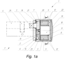
- fig. 1a shows the driving device for unlocking and locking a lock, having the housing in the form of a bush having teeth from the inner side
- fig. 2 shows an exploded perspective view of the driving device of fig. 1
- fig. 3 shows an A-A cross section of fig. 1
- fig. 3a shows a preferred construction of the electric cell being the electric energy source, fig.
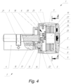
- FIG. 4 shows a longitudinal section of a driving device for unlocking and locking a lock
- fig. 4a shows an A-A cross section of fig. 4
- fig. 5 shows an exploded perspective view of the driving device of fig. 4
- fig. 6 shows a longitudinal section of a driving device in a fourth embodiment of the invention
- fig. 6a shows a B-B cross section of fig. 6
- fig. 7 shows an exploded perspective view of the driving device of fig. 6
- fig. 8 shows a longitudinal section of the driving device in a fifth embodiment of the invention
- fig. 8a shows a C-C cross-section of fig. 8 , fig.
- FIG. 9 shows an exploded perspective view of the driving device of fig. 7
- fig. 10 shows a longitudinal section of the driving device in a sixth embodiment of the invention
- fig. 11a shows a driving device where the electric energy source is in a shape of a cylinder with a centrally-positioned opening, as viewed from the front after removing the cover from the housing
- fig. 11b shows a longitudinal section of two layered flat electric energy sources in a shape of rings surrounding the motor
- fig. 12a shows a layered flat electric energy source in a shape of a cylinder with the eccentrically positioned opening, in which the motor is held, in a front view
- FIG. 12b shows a longitudinal section of two layered flat electric energy sources in a shape of a cylinder and with the eccentrically positioned opening, the electric energy sources surrounding the motor
- fig. 13a shows a layered flat electric energy source having a cavity, in which the motor is placed, in a front view
- fig. 13b shows a longitudinal section of two layered flat electric energy sources having a cavity, in which the motor is placed
- fig. 14a shows two layered electric energy sources of a shape similar to that of a half-ring, surrounding the driving motor, with layers in a form of sectors of cylindrical surfaces, in a front view, fig.
- FIG. 14b shows a longitudinal section of two layered electric energy sources of a shape similar to that of a half-ring, surrounding the driving motor, with layers in a form of sectors of cylindrical surfaces
- fig. 15a shows a layered, wound electric energy source in a shape of an open ring, surrounding the driving motor, in a front view
- fig. 15b shows a longitudinal section of a layered, wound electric energy source in a shape of an open ring, surrounding the driving motor
- fig. 15c shows a transversal cross section of a layered, wound electric energy source in a shape of an open ring, with a method for winding layers being shown, fig.
- 16a shows two layered wound electric energy sources of a shape similar to that of a half-ring, surrounding the driving motor, in a front view
- fig. 16b shows a longitudinal cross section of two layered wound electric energy sources of a shape similar to that of a half-ring, surrounding a driving motor
- fig. 16c shows a cross-section of two layered wound electric energy sources of a shape similar to that of a half-ring, with a method for winding layers being shown
- fig. 17a shows a driving device when ab electric energy source is in a shape of a cylinder with a centrally-positioned opening, in a front view after removing the frontal part from the housing, fig.
- FIG. 17b shows a longitudinal section of an electric energy source in a form of a ring, whose layers are wound spirally in the form of a web around the central opening where the driving motor is placed
- fig. 18a shows two layered electric energy sources in a shape of an open ring, surrounding a motor, whose layers are in a form of sectors of cylindrical surfaces, in a front view
- fig. 18b shows a longitudinal section of two layered electric energy sources in a shape of an open ring, surrounding a motor, with layers in a form of sectors of cylindrical surfaces
- fig. 19a shows four layered electric energy sources in a shape of a ring segment, surrounding a driving motor, with layers in a form of sectors of cylindrical surfaces, in a front view
- fig. 19b shows a longitudinal cross section of four layered electric energy sources in a shape of a ring segment, surrounding a driving motor, with layers in a form of sectors of cylindrical surfaces.
- a driving device 1 for unlocking and locking a lock 1' enabling access to protected areas has a cylindrical housing 5.
- the housing is made in a form of a bush covered at the front with a cover 19.
- the driving device 1 comprises a single electric energy source 9, having a form of a cylinder with a coaxially positioned opening 11.
- the electric energy source 9 is fitted with an anode, cathode and separator, all spirally wound in the form of a web around the through hole 11.
- the outer surface of the electric energy source 9 is the protective housing 12.
- a driving motor 10 is arranged for transmitting drive to a rotary control element 3 for the lock 1' mechanism by means of a gear assembly 6.
- the lock 1' has a body 4, in which the control element 3 is seated rotatably.
- a preferred construction of the electric energy source, where anode, cathode and separator are all spirally wound around the through hole is shown in fig. 3a .
- the driving device 1 is fitted with a base 2 fixed with respect to the lock 1', with the gear assembly 6, electric energy source 9 and driving motor 10 being seated fixedly with respect to the base.
- the driving device 1 is fitted with a support plate 7 that divides the space inside the housing 5 into a first chamber 22, where the driving motor 10 and the electric energy source 9 are held, and a second chamber 23, where the gear assembly 6 is held.
- the control element 3 for the lock 1' mechanism is seated on a toothed wheel 16 being one of the wheels of the gear assembly 6, and the housing 5 is in a form of a rotary bush seated in a bearing in the base 2 and the housing, from the inner side, has teeth 15 engaging with the toothed wheel 16 of the gear assembly 6, on which the control element 3 for the lock 1' mechanism is seated.
- the control element 3 for the lock 1' mechanism is seated on the toothed wheel 16 being one of the wheels of the gear assembly 6, and the housing 5 is in a form of a rotary bush, in which a ring 17 with teeth 18 is seated, the teeth engaging with the toothed wheel 16 of the gear assembly 6, on which the control element 3 for the lock 1' mechanism is seated.
- the gear assembly 6 of the driving device 1 comprises a coupling 13, which makes it possible to uncouple the gear 6 connecting the control element 3 to the driving motor 10, with the driving motor 10 being an electric motor.
- the coupling 13 makes it possible to manually control the lock more easily by rotation of the housing 5, with no resistance from the driving motor 10.
- the driving device 1 is fitted with an electronic control unit 8, which controls the driving motor 10.
- the electronic control unit 8 is controlled wirelessly by means of computer software, preferably a mobile device application, via a wireless connection.
- the electronic control unit 8 may also be controlled wirelessly via a Bluetooth wireless connection.
- a driving device 1 for unlocking and locking a lock 1' enabling access to protected areas has a housing 5 in a form of a can covered at the front with the frontal part 2. Inside the housing 5 there are two electric energy sources 9, a driving motor 10 and a gear assembly 6. The driving device 1 is fitted with a support plate 7 dividing the space inside the housing 5 into a first chamber 19, where the driving motor 10 and two electric energy sources 9 are held, and a second chamber 20, where the gear assembly 6 is held.
- the driving motor 10 is an electric motor.
- the lock 1' has the body 4, in which a control element 3 is seated rotatably for moving a dog 21 of the lock 1'.
- the driving motor 10 transmits drive to the control element 3 for the lock 1' mechanism by means of the gear assembly 6 and a ring 17 with teeth 18. Rotation of the driving motor causes rotation of the housing 5 and control element 3 by the toothed wheel 16 rolling along the ring 17 with the teeth 18.
- the electric energy sources 9 are shaped such that they at least partially surround the driving motor 10.
- the outer surface of the electric energy source 9 is the protective housing 12. In the area of the cross-section through the single electric energy source 9 there are at least two points such that a line segment joining these points passes through the area of the cross-section of the driving motor 10, which is evident, inter alia, in fig. 4a .
- electric energy sources 9 of layered structure were used, where anode, cathode and separator are all arranged in layers, the plane of which is perpendicular to the axis of the driving motor 10.
- the protective housing 12 of the electric energy source 9 has a through hole 11, in which the driving motor 10 is arranged.
- the protective housing 12 of the electric energy source 9 is wheel-shaped, and the opening 11 is positioned coaxially.
- the opening 11 is positioned eccentrically.
- the protective housing 12 of the electric energy source 9 has a cavity 14, in which the driving motor 10 is arranged.
- the shape of the cavity 14 is cross-sectionally a segment of a wheel.
- the housing 5 is seated in a bearing rotatably with respect to the body 4 of the lock 1' and is connected fixedly with the control element 3 for the lock 1'.
- the driving device 1 is fitted with the ring 17 with teeth 18 cooperating with the toothed wheel 16, being one of the wheels of the gear assembly 6 and seated in a bearing in the housing 5.
- the ring 17 is positioned coaxially with the rotary housing 5 and fixedly with respect to the body 4 of the lock 1'.
- the ring 17 is arranged between the gear assembly 6 and the lock 1'.
- the ring 17 is affixed to the lock 1' by means of a screw 15, but it is clear that in other embodiments of the invention the fixed connection of the ring 17 and the lock 1' may be realised with the use of other known methods, for example by means of gluing, riveting or shaping.
- the teeth 18 of the ring 17 are inner teeth, whereas in the embodiment of the invention shown in fig. 10 , the teeth 18 of the ring 17 are outer teeth.
- the driving device 1 is fitted with an electronic control unit 8 which controls the driving motor 10.
- the electronic control unit 8 is held between the driving motor 10 and the frontal part 2 of the housing 5.
- the electronic control unit 8 is fitted with a first sensor 26 cooperating with a manual control button 25 arranged on the frontal part 2 of the driving device 1.
- the electronic control unit 8 is fitted with a second sensor 27 which establishes angular position of the rotary housing 5.
- the second sensor 27 is an accelerometer (a sensor establishing angular position of the rotary housing 5 with respect to the gravity field of the Earth).
- the electronic control unit 8 is controlled wirelessly by means of computer software, preferably a mobile device application, via a wireless connection.
- the electronic control unit 8 may also be controlled wirelessly via a Bluetooth wireless connection.
- the housing 5 is connected to the control element 3 by means of a shaped releasable connection 22.
- the housing 5 is fitted with an electric socket 23 accessible after disconnection of the shaped releasable connection 22 and invisible in the connected position.
- the electric socket 23 is a micro USB type socket intended to deliver supply voltage, charge the electric energy source 9 and transfer data.
- the shaped releasable connection of the housing 5 and the control element 3 may of course be realised by other known methods.
- the electric energy source 9 is so shaped that it at least partially surrounds the driving motor 10, and in the area of cross-section through an individual electric energy source 9 there are at least two points such that a line segment joining these points passes through the area of cross-section of the driving motor 10.
- the electric energy source 9 is in the shape of a cylinder with a wheel-shaped opening 11, positioned coaxially, and in the embodiment of the invention shown in fig. 6 , fig. 6a and fig. 7 , fig. 12a, fig. 12b , the opening 11 is positioned eccentrically. Inside the opening 11 there is the driving motor 10.
- the electric energy source 9 has a cavity 14, in which the driving motor 10 is arranged.
- the shape of the cavity 14 in cross-section is a segment of a wheel.
- the protective housing 12 of the electric energy source 9 is a segment of a ring, the axis of whose is parallel to the axis of the driving motor 10.
- the electric energy source 9 is fitted with an anode 9a, cathode 9c and separator 9b, all spirally wound in a form of a web around the through hole 11.
- the electric energy source 9 is fitted with the anode 9a, cathode 9c and separator 9b, all arranged in layers being sectors of cylindrical surfaces of an axis parallel to the axis of the driving motor 10.
- the electric energy source 9 is fitted with an anode, cathode and separator all spirally wound and shaped in the form of an open ring, as in fig. 15a, fig. 15b, fig.15c or ring segments, as in fig. 16a, fig. 16b, fig. 16c ,
- the electric energy source 9 may also have other forms not shown in the picture, the forms fulfilling the requirements that the electric energy source 9 is so shaped that it at least partially surrounds the driving motor 10.
- the energy source 9 being so shaped and arranged with respect to the driving motor 10 enables essential reduction of the overall dimensions of the driving device 1.
- the electric energy source 9 is a primary or secondary electric cell.
- the driving device 1 is arranged at the inner side (not shown) of an entrance to access-protected areas and on the opposite side to the key-controlled part of the lock 1'.
Landscapes
- Physics & Mathematics (AREA)
- Electromagnetism (AREA)
- Engineering & Computer Science (AREA)
- Computer Networks & Wireless Communication (AREA)
- General Physics & Mathematics (AREA)
- Connection Of Motors, Electrical Generators, Mechanical Devices, And The Like (AREA)
- Lock And Its Accessories (AREA)
Claims (11)
- Dispositif d'entraînement (1) pour verrouiller et déverrouiller une serrure permettant l'accès à des zones protégées, comprenant au sein de de son logement (5): une ensemble engrenage (6), au moins une source d'énergie électrique (9) dans une boîtier de protection (12) et un moteur d'entraînement électrique (10), pour transmettre d'entraînement à un organe de réglage rotatif de la mécanisme de verrouillage par ensemble engrenage (6), caractérisé en ce qu'une source individuelle d'énergie électrique (9) est conformée de telle manière que avec sa forme, de la section transversale à travers d'un moteur d'entraînement (10) et la source d'énergie électrique (9), elle au moins partiellement entoure le moteur d'entraînement (10), c'est-à-dire, sur la surface de la section transversale il y a au moins deux points tels que un segment de ligne reliant ce deux points traverse la surface de section transversale du moteur d'entraînement (10).
- Dispositif d'entraînement (1) selon la revendication 1, caractérisé en ce qu'il est muni d'une base (2) sur laquelle l'ensemble engrenage (6), au moins une source d'énergie électrique (9) et le moteur d'entraînement (10) sont logés de façon fixe par rapport à la base.
- Dispositif d'entraînement (1) selon la revendication 1, caractérisé en ce que le logement (5) est muni d'une prise de courant (23), de préférence micro USB Type C prise de courant, destinée à charger la source d'énergie électrique (9).
- Dispositif d'entraînement (1) selon la revendication 1, caractérisé en ce que la boîtier de protection (12) de la source d'énergie électrique (9) a un trou traversant (11), dans lequel le moteur d'entraînement (10) est disposé, la boîtier de protection (12) de la source d'énergie électrique (9) étant en forme de roue en coupe transversale, avec l'ouverture (11) étant placé de manière coaxiale ou excentrique.
- Dispositif d'entraînement (1) selon la revendication 1, caractérisé en ce que la boîtier de protection (12) de la source d'énergie électrique (9) a une cavité (14), dans laquelle le moteur d'entraînement (10) est disposé, la forme de la section transversale de cavité (14) étant un segment d'une roue.
- Dispositif d'entraînement (1) selon la revendication 1, caractérisé en ce que la boîtier de protection (12) de la source d'énergie électrique (9) est un segment d'anneau, dont l'axe est parallèle à l'axe du moteur d'entraînement (10).
- Dispositif d'entraînement (1) selon la revendication 1, caractérisé en ce que la source d'énergie électrique (9) est soit une cellule électrique primaire, soit une cellule électrique secondaire.
- Dispositif d'entraînement (1) selon la revendication 4, caractérisé en ce que la source d'énergie électrique (9) est muni d'une anode, d'une cathode et d'un séparateur, tous enroulés en spirale en forme de bande autour du trou traversant (11) ou tous disposés en couches, dont le plan est perpendiculaire à l'axe du moteur d'entraînement (10).
- Dispositif d'entraînement (1) selon la revendication 4, caractérisé en ce que la source d'énergie électrique (9) est muni d'une anode, d'une cathode et d'un séparateur, tous disposés en couches étant des zones des surfaces cylindriques d'un axe parallèle à l'axe du moteur d'entraînement (10).
- Dispositif d'entraînement (1) selon la revendication 1, caractérisé en ce que l'ensemble engrenage (6) comprise un accouplement.
- Dispositif d'entraînement (1) selon la revendication 1, caractérisé en ce que il est muni d'une unité de commande électronique (8) pour contrôler le moteur d'entraînement (10) et de préférence munie d'un capteur premier (26) coopérant avec un bouton de commande manuelle (25), disposé sur la partie frontale du dispositif d'entraînement (1), l'unité de commande électronique (8) étant munie d'un capteur seconde (27), qui établit une position angulaire du logement rotatif (5), le capteur seconde étant de préférence un accéléromètre (capteur de champ gravitationnel), l'unité de commande électronique (8) étant commandée sans fil, de préférence par un logiciel, de préférence une application de dispositif mobile, à l'aide d'une connexion sans fil.
Applications Claiming Priority (3)
| Application Number | Priority Date | Filing Date | Title |
|---|---|---|---|
| PL421765A PL232587B1 (pl) | 2017-05-31 | 2017-05-31 | Urządzenie napędowe do otwierania i zamykania zamka |
| PL421766A PL232588B1 (pl) | 2017-05-31 | 2017-05-31 | Urządzenie napędowe do otwierania i zamykania zamka |
| PCT/IB2018/053802 WO2018220522A1 (fr) | 2017-05-31 | 2018-05-29 | Dispositif d'entraînement pour déverrouiller et verrouiller un verrou |
Publications (3)
| Publication Number | Publication Date |
|---|---|
| EP3631128A1 EP3631128A1 (fr) | 2020-04-08 |
| EP3631128B1 true EP3631128B1 (fr) | 2025-02-12 |
| EP3631128C0 EP3631128C0 (fr) | 2025-02-12 |
Family
ID=62875068
Family Applications (1)
| Application Number | Title | Priority Date | Filing Date |
|---|---|---|---|
| EP18739925.8A Active EP3631128B1 (fr) | 2017-05-31 | 2018-05-29 | Dispositif d'entraînement pour déverrouiller et verrouiller un verrou |
Country Status (8)
| Country | Link |
|---|---|
| US (1) | US11578505B2 (fr) |
| EP (1) | EP3631128B1 (fr) |
| JP (1) | JP7138703B2 (fr) |
| CN (1) | CN110945200B (fr) |
| CA (1) | CA3064347C (fr) |
| ES (1) | ES3026787T3 (fr) |
| RU (1) | RU2735205C1 (fr) |
| WO (1) | WO2018220522A1 (fr) |
Families Citing this family (7)
| Publication number | Priority date | Publication date | Assignee | Title |
|---|---|---|---|---|
| US20230243184A1 (en) * | 2017-12-28 | 2023-08-03 | Yoho Innovative Technology Limited | Telescopic electromechanical dual-control smart lock |
| FR3091545B1 (fr) * | 2019-01-07 | 2021-11-26 | Opendoors | Dispositif électromécanique d’actionnement de serrure à bouton de manœuvre désaxé |
| DK181041B1 (en) * | 2020-06-24 | 2022-10-11 | Laas Aps | HOUSING FOR A LOCKING SYSTEM |
| DK180762B1 (en) * | 2020-06-24 | 2022-02-28 | Laas Aps | Mounting plate for a lock system |
| EP4182523A1 (fr) * | 2020-07-17 | 2023-05-24 | Desi Alarm Ve Güvenlik Sistemleri Sanayi Ve Ticaret Anonim Sirketi | Bouton rotatif pour barillet de serrure et procédé de détection et d'actionnement de barillet de serrure |
| PL242944B1 (pl) * | 2020-08-14 | 2023-05-22 | Litwinski Artur | Urządzenie napędowe, zwłaszcza do otwierania i zamykania na przykład zamka |
| PL242787B1 (pl) * | 2020-08-14 | 2023-04-24 | Litwinski Artur | Urządzenie napędowe, zwłaszcza do zamykania i otwierania na przykład zamka |
Family Cites Families (27)
| Publication number | Priority date | Publication date | Assignee | Title |
|---|---|---|---|---|
| AT396163B (de) | 1991-06-11 | 1993-06-25 | Evva Werke | Schloss mit wenigstens einem motorisch verdrehbaren zylinderkern und verschlussanlage |
| JPH11480A (ja) * | 1997-06-12 | 1999-01-06 | Sanyo Electric Co Ltd | 分割可能な充電式電気機器 |
| JP4160143B2 (ja) * | 1998-01-29 | 2008-10-01 | アイシン機工株式会社 | 直動アクチュエータ |
| DE19807553C1 (de) * | 1998-02-23 | 1999-07-01 | Keso Gmbh | Antriebsvorrichtung für ein Schloß, einen Schließzylinder oder dgl. |
| JP2000008679A (ja) * | 1998-06-26 | 2000-01-11 | Tescon Co Ltd | クレセント |
| JP2009068311A (ja) * | 2007-09-18 | 2009-04-02 | Union Corp | サムターン装置 |
| US7516633B1 (en) | 2008-01-16 | 2009-04-14 | Ez Trend Technology Co., Ltd. | Electric lock |
| EP2365475B1 (fr) * | 2010-03-12 | 2013-05-08 | DESI Alarm ve Güvenlik Sistemleri Sanayi ve Ticaret Ltd. Sti. | Verrou de cylindre électrique |
| US9680272B2 (en) | 2012-02-17 | 2017-06-13 | Semiconductor Energy Laboratory Co., Ltd. | Method for forming negative electrode and method for manufacturing lithium secondary battery |
| RU2493344C1 (ru) * | 2012-04-23 | 2013-09-20 | Общество С Ограниченной Ответственностью "Инвек" | Способ отпирания и запирания замка и замок, реализующий способ (варианты) |
| CN202866446U (zh) * | 2012-10-18 | 2013-04-10 | 孙新利 | 电动锁具的驱动装置 |
| US8555684B1 (en) * | 2013-01-21 | 2013-10-15 | Jie-Fu Chen | Electronic lock |
| US9574372B2 (en) | 2013-03-15 | 2017-02-21 | August Home, Inc. | Intelligent door lock system that minimizes inertia applied to components |
| US9487971B2 (en) | 2013-03-15 | 2016-11-08 | Spectrum Brands, Inc. | Electro-mechanical locks with bezel turning function |
| DK177991B1 (en) * | 2013-10-07 | 2015-02-16 | Poly Care Aps | Motorised door lock actuator |
| WO2015138747A1 (fr) | 2014-03-14 | 2015-09-17 | August Home, Inc. | Système de verrouillage de porte intelligent servant à minimaliser l'inertie |
| US20150292244A1 (en) | 2014-04-10 | 2015-10-15 | Gleyn Beatty | Proximity Padlock |
| IL232413B (en) | 2014-05-01 | 2018-07-31 | Knock Nlock Ltd | Electronically operated lock |
| JP6411824B2 (ja) * | 2014-09-10 | 2018-10-24 | 株式会社熊平製作所 | 錠装置 |
| JP6488137B2 (ja) | 2015-01-28 | 2019-03-20 | 日立アプライアンス株式会社 | 電気掃除機 |
| WO2016196192A1 (fr) | 2015-06-05 | 2016-12-08 | Sargent & Greenleaf, Inc. | Serrure électromécanique de sécurité élevée |
| GB201516435D0 (en) * | 2015-09-16 | 2015-10-28 | Glue Together Ab | A smart lock |
| DE202016002087U1 (de) | 2016-03-30 | 2016-04-20 | Felix Mayer | Elektronisches Fahrradschloss |
| CN206128881U (zh) * | 2016-08-02 | 2017-04-26 | 江苏雷利电机股份有限公司 | 门锁驱动装置和应用其的电控门锁 |
| CN206117404U (zh) * | 2016-10-09 | 2017-04-19 | 北京摩拜科技有限公司 | 电机碟刹组件、电机以及车辆 |
| PL233824B1 (pl) * | 2017-05-31 | 2019-11-29 | Artur Litwinski | Urzadzenie napedowe do otwierania i zamykania zamka |
| CN209637411U (zh) * | 2018-10-12 | 2019-11-15 | 深圳市海月云科技有限公司 | 一种智能开锁装置 |
-
2018
- 2018-05-29 EP EP18739925.8A patent/EP3631128B1/fr active Active
- 2018-05-29 RU RU2019141650A patent/RU2735205C1/ru active
- 2018-05-29 US US16/617,225 patent/US11578505B2/en active Active
- 2018-05-29 ES ES18739925T patent/ES3026787T3/es active Active
- 2018-05-29 CN CN201880048107.XA patent/CN110945200B/zh active Active
- 2018-05-29 WO PCT/IB2018/053802 patent/WO2018220522A1/fr not_active Ceased
- 2018-05-29 JP JP2020516968A patent/JP7138703B2/ja active Active
- 2018-05-29 CA CA3064347A patent/CA3064347C/fr active Active
Also Published As
| Publication number | Publication date |
|---|---|
| JP2020521904A (ja) | 2020-07-27 |
| EP3631128A1 (fr) | 2020-04-08 |
| US11578505B2 (en) | 2023-02-14 |
| CA3064347A1 (fr) | 2018-12-06 |
| RU2735205C1 (ru) | 2020-10-28 |
| CN110945200B (zh) | 2021-04-27 |
| JP7138703B2 (ja) | 2022-09-16 |
| CN110945200A (zh) | 2020-03-31 |
| US20200149319A1 (en) | 2020-05-14 |
| WO2018220522A1 (fr) | 2018-12-06 |
| EP3631128C0 (fr) | 2025-02-12 |
| CA3064347C (fr) | 2024-06-25 |
| ES3026787T3 (en) | 2025-06-12 |
Similar Documents
| Publication | Publication Date | Title |
|---|---|---|
| EP3631128B1 (fr) | Dispositif d'entraînement pour déverrouiller et verrouiller un verrou | |
| EP3631129B1 (fr) | Dispositif d'entraînement pour déverrouiller et verrouiller une serrure | |
| AU2011101534B4 (en) | Door Operator | |
| EP2974896B1 (fr) | Dispositif d'ouverture et de fermeture de porte | |
| PL232587B1 (pl) | Urządzenie napędowe do otwierania i zamykania zamka | |
| FI12336U1 (fi) | Aukaisulaite ja vääntöosa | |
| EP4196654A1 (fr) | Dispositif d'entraînement destiné particulièrement à l'ouverture et la fermeture, par exemple verrou | |
| US12239587B2 (en) | Wheelchair propulsion system | |
| EP3354827A1 (fr) | Dispositif de commande de serrure de porte | |
| CN101269486B (zh) | 手柄旋转调节装置 | |
| JP5124843B2 (ja) | トルクリミッター付のクラッチ機構 | |
| PL242944B1 (pl) | Urządzenie napędowe, zwłaszcza do otwierania i zamykania na przykład zamka | |
| CN218438769U (zh) | 用于门锁的驱动机构、门锁 | |
| CN215529322U (zh) | 一种矿山救援无线通信装置 | |
| CN118721170B (zh) | 电动外骨骼的紧急充能结构以及电动外骨骼 | |
| CN109944183A (zh) | 一种车位锁 | |
| WO2021112783A1 (fr) | Mécanisme d'ouverture et de fermeture des systèmes de panneaux coulissants | |
| PL242786B1 (pl) | Urządzenie napędowe, zwłaszcza do sterowania na przykład zamka | |
| CN109098538A (zh) | 锁把装置 | |
| AU2013203931A1 (en) | Modular Gear Box of a Door or Gate Opener | |
| CN110644848A (zh) | 一种智能锁轴离合器 |
Legal Events
| Date | Code | Title | Description |
|---|---|---|---|
| STAA | Information on the status of an ep patent application or granted ep patent |
Free format text: STATUS: UNKNOWN |
|
| STAA | Information on the status of an ep patent application or granted ep patent |
Free format text: STATUS: THE INTERNATIONAL PUBLICATION HAS BEEN MADE |
|
| PUAI | Public reference made under article 153(3) epc to a published international application that has entered the european phase |
Free format text: ORIGINAL CODE: 0009012 |
|
| STAA | Information on the status of an ep patent application or granted ep patent |
Free format text: STATUS: REQUEST FOR EXAMINATION WAS MADE |
|
| 17P | Request for examination filed |
Effective date: 20191219 |
|
| AK | Designated contracting states |
Kind code of ref document: A1 Designated state(s): AL AT BE BG CH CY CZ DE DK EE ES FI FR GB GR HR HU IE IS IT LI LT LU LV MC MK MT NL NO PL PT RO RS SE SI SK SM TR |
|
| AX | Request for extension of the european patent |
Extension state: BA ME |
|
| DAV | Request for validation of the european patent (deleted) | ||
| DAX | Request for extension of the european patent (deleted) | ||
| RAP1 | Party data changed (applicant data changed or rights of an application transferred) |
Owner name: TEDEE IP SPOLKA Z OGRANICZONA ODPOWIEDZIALNOSCIA |
|
| RIN1 | Information on inventor provided before grant (corrected) |
Inventor name: LITWINSKI, ARTUR |
|
| GRAP | Despatch of communication of intention to grant a patent |
Free format text: ORIGINAL CODE: EPIDOSNIGR1 |
|
| STAA | Information on the status of an ep patent application or granted ep patent |
Free format text: STATUS: GRANT OF PATENT IS INTENDED |
|
| INTG | Intention to grant announced |
Effective date: 20240904 |
|
| GRAS | Grant fee paid |
Free format text: ORIGINAL CODE: EPIDOSNIGR3 |
|
| GRAA | (expected) grant |
Free format text: ORIGINAL CODE: 0009210 |
|
| STAA | Information on the status of an ep patent application or granted ep patent |
Free format text: STATUS: THE PATENT HAS BEEN GRANTED |
|
| AK | Designated contracting states |
Kind code of ref document: B1 Designated state(s): AL AT BE BG CH CY CZ DE DK EE ES FI FR GB GR HR HU IE IS IT LI LT LU LV MC MK MT NL NO PL PT RO RS SE SI SK SM TR |
|
| REG | Reference to a national code |
Ref country code: GB Ref legal event code: FG4D |
|
| REG | Reference to a national code |
Ref country code: CH Ref legal event code: EP |
|
| REG | Reference to a national code |
Ref country code: DE Ref legal event code: R096 Ref document number: 602018079072 Country of ref document: DE |
|
| REG | Reference to a national code |
Ref country code: IE Ref legal event code: FG4D |
|
| U01 | Request for unitary effect filed |
Effective date: 20250312 |
|
| U07 | Unitary effect registered |
Designated state(s): AT BE BG DE DK EE FI FR IT LT LU LV MT NL PT RO SE SI Effective date: 20250320 |
|
| U20 | Renewal fee for the european patent with unitary effect paid |
Year of fee payment: 8 Effective date: 20250331 |
|
| REG | Reference to a national code |
Ref country code: ES Ref legal event code: FG2A Ref document number: 3026787 Country of ref document: ES Kind code of ref document: T3 Effective date: 20250612 |
|
| PG25 | Lapsed in a contracting state [announced via postgrant information from national office to epo] |
Ref country code: RS Free format text: LAPSE BECAUSE OF FAILURE TO SUBMIT A TRANSLATION OF THE DESCRIPTION OR TO PAY THE FEE WITHIN THE PRESCRIBED TIME-LIMIT Effective date: 20250512 |
|
| PG25 | Lapsed in a contracting state [announced via postgrant information from national office to epo] |
Ref country code: PL Free format text: LAPSE BECAUSE OF FAILURE TO SUBMIT A TRANSLATION OF THE DESCRIPTION OR TO PAY THE FEE WITHIN THE PRESCRIBED TIME-LIMIT Effective date: 20250212 |
|
| PGFP | Annual fee paid to national office [announced via postgrant information from national office to epo] |
Ref country code: ES Payment date: 20250602 Year of fee payment: 8 |
|
| PG25 | Lapsed in a contracting state [announced via postgrant information from national office to epo] |
Ref country code: IS Free format text: LAPSE BECAUSE OF FAILURE TO SUBMIT A TRANSLATION OF THE DESCRIPTION OR TO PAY THE FEE WITHIN THE PRESCRIBED TIME-LIMIT Effective date: 20250612 Ref country code: NO Free format text: LAPSE BECAUSE OF FAILURE TO SUBMIT A TRANSLATION OF THE DESCRIPTION OR TO PAY THE FEE WITHIN THE PRESCRIBED TIME-LIMIT Effective date: 20250512 |
|
| PG25 | Lapsed in a contracting state [announced via postgrant information from national office to epo] |
Ref country code: HR Free format text: LAPSE BECAUSE OF FAILURE TO SUBMIT A TRANSLATION OF THE DESCRIPTION OR TO PAY THE FEE WITHIN THE PRESCRIBED TIME-LIMIT Effective date: 20250212 |
|
| PG25 | Lapsed in a contracting state [announced via postgrant information from national office to epo] |
Ref country code: GR Free format text: LAPSE BECAUSE OF FAILURE TO SUBMIT A TRANSLATION OF THE DESCRIPTION OR TO PAY THE FEE WITHIN THE PRESCRIBED TIME-LIMIT Effective date: 20250513 |
|
| PGFP | Annual fee paid to national office [announced via postgrant information from national office to epo] |
Ref country code: CH Payment date: 20250601 Year of fee payment: 8 |
|
| PGFP | Annual fee paid to national office [announced via postgrant information from national office to epo] |
Ref country code: TR Payment date: 20250521 Year of fee payment: 8 |
|
| PG25 | Lapsed in a contracting state [announced via postgrant information from national office to epo] |
Ref country code: SM Free format text: LAPSE BECAUSE OF FAILURE TO SUBMIT A TRANSLATION OF THE DESCRIPTION OR TO PAY THE FEE WITHIN THE PRESCRIBED TIME-LIMIT Effective date: 20250212 |
|
| PG25 | Lapsed in a contracting state [announced via postgrant information from national office to epo] |
Ref country code: CZ Free format text: LAPSE BECAUSE OF FAILURE TO SUBMIT A TRANSLATION OF THE DESCRIPTION OR TO PAY THE FEE WITHIN THE PRESCRIBED TIME-LIMIT Effective date: 20250212 |
|
| PGFP | Annual fee paid to national office [announced via postgrant information from national office to epo] |
Ref country code: IE Payment date: 20250829 Year of fee payment: 8 |
|
| PG25 | Lapsed in a contracting state [announced via postgrant information from national office to epo] |
Ref country code: SK Free format text: LAPSE BECAUSE OF FAILURE TO SUBMIT A TRANSLATION OF THE DESCRIPTION OR TO PAY THE FEE WITHIN THE PRESCRIBED TIME-LIMIT Effective date: 20250212 |
|
| PLBE | No opposition filed within time limit |
Free format text: ORIGINAL CODE: 0009261 |
|
| STAA | Information on the status of an ep patent application or granted ep patent |
Free format text: STATUS: NO OPPOSITION FILED WITHIN TIME LIMIT |
|
| 26N | No opposition filed |
Effective date: 20251113 |
|
| PG25 | Lapsed in a contracting state [announced via postgrant information from national office to epo] |
Ref country code: MC Free format text: LAPSE BECAUSE OF FAILURE TO SUBMIT A TRANSLATION OF THE DESCRIPTION OR TO PAY THE FEE WITHIN THE PRESCRIBED TIME-LIMIT Effective date: 20250212 |
|
| PGFP | Annual fee paid to national office [announced via postgrant information from national office to epo] |
Ref country code: GB Payment date: 20260331 Year of fee payment: 9 |