EP3631146B1 - Ensemble clé à dispositif de centrage tubulaire - Google Patents
Ensemble clé à dispositif de centrage tubulaire Download PDFInfo
- Publication number
- EP3631146B1 EP3631146B1 EP18732962.8A EP18732962A EP3631146B1 EP 3631146 B1 EP3631146 B1 EP 3631146B1 EP 18732962 A EP18732962 A EP 18732962A EP 3631146 B1 EP3631146 B1 EP 3631146B1
- Authority
- EP
- European Patent Office
- Prior art keywords
- tubular
- assembly
- wrench
- primary contact
- wrench assembly
- Prior art date
- Legal status (The legal status is an assumption and is not a legal conclusion. Google has not performed a legal analysis and makes no representation as to the accuracy of the status listed.)
- Active
Links
Images



Classifications
-
- E—FIXED CONSTRUCTIONS
- E21—EARTH OR ROCK DRILLING; MINING
- E21B—EARTH OR ROCK DRILLING; OBTAINING OIL, GAS, WATER, SOLUBLE OR MELTABLE MATERIALS OR A SLURRY OF MINERALS FROM WELLS
- E21B19/00—Handling rods, casings, tubes or the like outside the borehole, e.g. in the derrick; Apparatus for feeding the rods or cables
- E21B19/16—Connecting or disconnecting pipe couplings or joints
- E21B19/161—Connecting or disconnecting pipe couplings or joints using a wrench or a spinner adapted to engage a circular section of pipe
-
- E—FIXED CONSTRUCTIONS
- E21—EARTH OR ROCK DRILLING; MINING
- E21B—EARTH OR ROCK DRILLING; OBTAINING OIL, GAS, WATER, SOLUBLE OR MELTABLE MATERIALS OR A SLURRY OF MINERALS FROM WELLS
- E21B19/00—Handling rods, casings, tubes or the like outside the borehole, e.g. in the derrick; Apparatus for feeding the rods or cables
- E21B19/16—Connecting or disconnecting pipe couplings or joints
- E21B19/161—Connecting or disconnecting pipe couplings or joints using a wrench or a spinner adapted to engage a circular section of pipe
- E21B19/163—Connecting or disconnecting pipe couplings or joints using a wrench or a spinner adapted to engage a circular section of pipe piston-cylinder actuated
-
- E—FIXED CONSTRUCTIONS
- E21—EARTH OR ROCK DRILLING; MINING
- E21B—EARTH OR ROCK DRILLING; OBTAINING OIL, GAS, WATER, SOLUBLE OR MELTABLE MATERIALS OR A SLURRY OF MINERALS FROM WELLS
- E21B19/00—Handling rods, casings, tubes or the like outside the borehole, e.g. in the derrick; Apparatus for feeding the rods or cables
- E21B19/16—Connecting or disconnecting pipe couplings or joints
- E21B19/161—Connecting or disconnecting pipe couplings or joints using a wrench or a spinner adapted to engage a circular section of pipe
- E21B19/164—Connecting or disconnecting pipe couplings or joints using a wrench or a spinner adapted to engage a circular section of pipe motor actuated
Definitions
- Embodiments disclosed herein relate to a wrench tool for coupling or decoupling tubulars in a drilling or workover operation utilized in the oil and gas industry.
- a wrench tool (also known as a "tong") is commonly used in the oil and gas industry to rotate a tubular when making up or breaking out a threaded connection.
- the wrench tool rotates a tubular relative to another tubular to thread the tubulars together during a make-up operation, and rotates the tubular in an opposite direction to unthread the tubulars from each other during a break-out operation.
- a spinner tool may be used in conjunction with the wrench tool.
- the spinner tool is a relatively low torque, high speed device used for the initial makeup of a threaded connection, while the wrench tool is a relatively high torque, low speed device that is used subsequently to the spinner tool to provide a greater amount of torque to complete the threaded connection.
- the wrench also known as a "power tong” may be composed of upper and lower torque bodies having a plurality of grippers that are moved into contact with the tubulars.
- the upper torque body is configured to rotate one of the tubulars relative to the other tubular, which is held stationary by the lower torque body, to couple or decouple the tubulars.
- One problem that often occurs is the grippers grip the tubular in a position such that the center axis of the tubular is offset from the center axis of the wrench. This is caused when some of the grippers contact the tubular prior to the other grippers, which results in a misalignment of the wrench with the center axis of the tubular.
- the improper alignment between the wrench and the center axis of the tubular often results in a misapplication of the appropriate amount of torque to a threaded connection, thereby potentially resulting in a leak in the threaded connection.
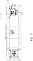
- the wrench tool 100 is brought into proximity with a first tubular that is held by a rotary spider on a rig floor for example.
- the grippers 150 of the lower clamp assembly 140 are actuated to grip the box end of the first tubular.
- a pin end of a second tubular is positioned on top of the box end of the first tubular by an elevator or top drive for example.
- the second tubular is rotated by a spinner tool (not shown) to initially make-up the threaded connection.
- one problem that often occurs with a conventional wrench assembly is that the grippers of the lower clamp assembly grip the box end of the first tubular in a position where the center axis of the first tubular is offset from the center axis of the wrench assembly 110. This may be caused when one of the grippers of the lower clamp assembly contact the first tubular prior to the other grippers of the lower clamp assembly, which results in a misalignment of the center axis of the wrench assembly 110 with the center axis of the first tubular.
- the grippers 150 of the lower clamp assembly 140 as described herein are configured to center the tubular within a central opening 115 of the wrench assembly 110.
- FIGS 5A and 5B are sectional views of the lower clamp assembly 140 along line 5-5 of Figure 3 .
- Each gripper 150 includes a piston 505 disposed within a housing 506, and a grip head 405 coupled to one end of the piston 505.
- the piston 505 is movable relative to the housing 506, such as by hydraulic fluid, to move the grip head 405 into and out of contact with the first tubular 630 (shown in Figure 5B ).
- the grip head 405 includes a primary contact plate 510 housing a die plate 515.
- the primary contact plate 510 is configured to contact the first tubular 630 prior to the die plate 515 to help center the first tubular 630 within the wrench assembly 110 before gripping.
- Figure 5B shows the grippers 150 of the lower clamp assembly 140 gripping the first tubular 630.
- the primary contact plates 510 of each of the grip heads 405 are in a second position such that the die plates 515 extend beyond the plane 625 of the primary contact plates 510.
- a biasing member 710 such as a spring, may be utilized to bias the primary contact plate 510 toward the first tubular 630.
- the first tubular 630 is contacted first by the primary contact plate 510, which allows movement of the first tubular 630 along the surface 700 prior to gripping by the gripping surface 620 of the die plate 515.
- the first tubular 630 may slide along the surface 700 towards the longitudinal axis 615 of the gripper 150.
- the first tubular 630 may be contacted by the respective primary contact plates 510 and move toward the respective longitudinal axes 615 as shown in Figure 5B .
- Figure 6B shows the primary contact plate 510 in a second position such that the gripping surface 620 of the die plate 515 extends beyond the plane 625.
- the wrench assembly 110 having grip heads 405 as described herein help center the first tubular 630 within the wrench assembly 110 before the die plate 515 engages the first tubular 630.
- the centering of the first tubular 630 aligns the center axis of the first tubular 630 with the center axis of the wrench assembly 110. Since the center axis of the wrench assembly 110 is the axis about which maximum torque is applied, then wrench assembly 110 effectively ensures that the maximum amount torque is being applied to the first tubular 630 to make up or break out a threaded connection.
Landscapes
- Engineering & Computer Science (AREA)
- Geology (AREA)
- Mining & Mineral Resources (AREA)
- Life Sciences & Earth Sciences (AREA)
- General Life Sciences & Earth Sciences (AREA)
- Fluid Mechanics (AREA)
- Mechanical Engineering (AREA)
- Environmental & Geological Engineering (AREA)
- Physics & Mathematics (AREA)
- Geochemistry & Mineralogy (AREA)
- Mounting, Exchange, And Manufacturing Of Dies (AREA)
- Moulds For Moulding Plastics Or The Like (AREA)
- Manipulator (AREA)
- Forging (AREA)
- Details Of Spanners, Wrenches, And Screw Drivers And Accessories (AREA)
Claims (11)
- Un ensemble de clé (110) comprenant ;
un ensemble de serrage supérieur (135) ; et
un ensemble de serrage inférieur (140) couplé à l'ensemble de serrage supérieur, dans lequel l'ensemble de serrage inférieur comprend plusieurs pinces (150) disposant chacune d'une tête de serrage (405) configurée pour serrer un élément tubulaire (630),
caractérisé par le fait que chaque tête de préhension comprend :
une plaque matrice (515) entourée par une plaque de contact primaire (510), la plaque matrice étant disposée dans une cavité centrale (600) formée dans une surface (700) de la plaque de contact primaire, où la surface de la plaque de contact primaire est configurée pour entrer en contact avec l'élément tubulaire avant qu'une surface de préhension (620) de la plaque matrice n'entre en contact avec l'élément tubulaire. - L'ensemble de clé (110) de la revendication 1, dans lequel la plaque de contact primaire présente des coins arrondis (610) configurés pour centrer l'élément tubulaire dans l'ensemble de clé.
- L'ensemble de clé (110) de la revendication 2, dans lequel la plaque de contact primaire est sollicitée par un élément de rappel (710) vers l'élément tubulaire.
- L'ensemble de clé (110) de la revendication 3, dans lequel la surface de préhension de la plaque matrice est disposée en dessous d'un plan de la plaque de contact primaire pendant le contact initial de la surface de la plaque de contact primaire avec l'élément tubulaire.
- L'ensemble de clé (110) de la revendication 4, dans lequel l'élément de rappel est configuré pour se comprimer de sorte que la surface de préhension de la plaque matrice s'étende au-delà du plan de la plaque de contact primaire pendant la préhension de l'élément tubulaire.
- L'ensemble de clé (110) de la revendication 5, dans lequel les coins arrondis sont configurés pour pousser l'élément tubulaire vers un axe central de l'ensemble de clé avant que la plaque matrice n'engage l'élément tubulaire.
- L'ensemble de clé (110) de la revendication 6, dans lequel les coins arrondis comprennent un biseau, un rayon ou un chanfrein.
- L'ensemble de clé (110) de la revendication 7, dans lequel l'ensemble de serrage supérieur est configuré pour serrer et faire tourner un deuxième élément tubulaire par rapport à l'élément tubulaire serré par l'ensemble de serrage inférieur, afin d'établir ou de rompre une connexion filetée entre le deuxième élément tubulaire et l'élément tubulaire serré par l'ensemble de serrage inférieur.
- L'ensemble de clé (110) de la revendication 1, dans lequel la plaque de contact primaire comprend un plan (625), dans lequel la plaque matrice est mobile entre une première position et une deuxième position et dans lequel la surface de préhension se trouve d'un côté du plan dans la première position et de l'autre côté du plan dans la deuxième position.
- L'ensemble de clé (110) de la revendication 3, dans lequel l'élément de rappel (710) comprend un ressort.
- L'ensemble de clé (110) de la revendication 9, dans lequel la surface de la plaque de contact primaire est disposée dans le plan.
Applications Claiming Priority (2)
| Application Number | Priority Date | Filing Date | Title |
|---|---|---|---|
| US15/609,315 US10753162B2 (en) | 2017-05-31 | 2017-05-31 | Wrench assembly with tubular centering device |
| PCT/US2018/031964 WO2018222362A1 (fr) | 2017-05-31 | 2018-05-10 | Ensemble clé comportant un dispositif de centrage tubulaire |
Publications (2)
| Publication Number | Publication Date |
|---|---|
| EP3631146A1 EP3631146A1 (fr) | 2020-04-08 |
| EP3631146B1 true EP3631146B1 (fr) | 2021-06-16 |
Family
ID=62685077
Family Applications (1)
| Application Number | Title | Priority Date | Filing Date |
|---|---|---|---|
| EP18732962.8A Active EP3631146B1 (fr) | 2017-05-31 | 2018-05-10 | Ensemble clé à dispositif de centrage tubulaire |
Country Status (5)
| Country | Link |
|---|---|
| US (1) | US10753162B2 (fr) |
| EP (1) | EP3631146B1 (fr) |
| CA (1) | CA3065076C (fr) |
| MX (2) | MX2019014210A (fr) |
| WO (1) | WO2018222362A1 (fr) |
Families Citing this family (2)
| Publication number | Priority date | Publication date | Assignee | Title |
|---|---|---|---|---|
| US12496667B2 (en) | 2023-02-14 | 2025-12-16 | Forum Us, Inc. | Wrench systems, methods, and related apparatus for determining angular misalignment |
| US12607078B1 (en) | 2025-02-21 | 2026-04-21 | Forum Us, Inc. | Hydraulic spider system and methods for use thereof |
Family Cites Families (8)
| Publication number | Priority date | Publication date | Assignee | Title |
|---|---|---|---|---|
| US4403666A (en) | 1981-06-01 | 1983-09-13 | Walker-Neer Manufacturing Co. Inc. | Self centering tongs and transfer arm for drilling apparatus |
| US5054550A (en) | 1990-05-24 | 1991-10-08 | W-N Apache Corporation | Centering spinning for down hole tubulars |
| US5791206A (en) | 1996-12-10 | 1998-08-11 | Ingersoll-Rand Company | Drill pipe handling mechanism |
| US6116118A (en) * | 1998-07-15 | 2000-09-12 | Wesch, Jr.; William E. | Gripping apparatus for power tongs and backup tools |
| CA2440579C (fr) * | 2002-09-12 | 2010-11-23 | National-Oilwell, L.P. | Amplificateur de la force des machoires commande par came pour saisir un element cylindrique |
| US7707914B2 (en) | 2003-10-08 | 2010-05-04 | Weatherford/Lamb, Inc. | Apparatus and methods for connecting tubulars |
| WO2008022424A1 (fr) * | 2006-08-24 | 2008-02-28 | Canrig Drilling Technology Ltd. | Clé dynamométrique pour matériel tubulaire de champ de pétrole |
| US8474806B2 (en) | 2009-01-26 | 2013-07-02 | T&T Engineering Services, Inc. | Pipe gripping apparatus |
-
2017
- 2017-05-31 US US15/609,315 patent/US10753162B2/en active Active
-
2018
- 2018-05-10 EP EP18732962.8A patent/EP3631146B1/fr active Active
- 2018-05-10 MX MX2019014210A patent/MX2019014210A/es unknown
- 2018-05-10 WO PCT/US2018/031964 patent/WO2018222362A1/fr not_active Ceased
- 2018-05-10 CA CA3065076A patent/CA3065076C/fr active Active
-
2019
- 2019-11-27 MX MX2023012332A patent/MX2023012332A/es unknown
Non-Patent Citations (1)
| Title |
|---|
| None * |
Also Published As
| Publication number | Publication date |
|---|---|
| CA3065076A1 (fr) | 2018-12-06 |
| US10753162B2 (en) | 2020-08-25 |
| MX2023012332A (es) | 2023-10-30 |
| MX2019014210A (es) | 2020-02-07 |
| US20180347297A1 (en) | 2018-12-06 |
| WO2018222362A1 (fr) | 2018-12-06 |
| EP3631146A1 (fr) | 2020-04-08 |
| CA3065076C (fr) | 2022-05-17 |
Similar Documents
| Publication | Publication Date | Title |
|---|---|---|
| EP3630414B1 (fr) | Ensemble clé à corps de torsion flottants | |
| EP2183460B1 (fr) | Dispositif de serrage et de rupture | |
| US8191638B2 (en) | Drill stem connection and method | |
| US20070068669A1 (en) | Pipe gripping ram | |
| US10767425B2 (en) | Wrench assembly with eccentricity sensing circuit | |
| EP3631146B1 (fr) | Ensemble clé à dispositif de centrage tubulaire | |
| AU2024259691B2 (en) | Apparatus And Methods For Tong Operation | |
| US11396780B2 (en) | Wrench for use with making and breaking a drill string | |
| WO1999006186A1 (fr) | Dispositif de demontage de tiges de forage | |
| US20220268112A1 (en) | Ergonomic shoe interface system for core drilling | |
| US3412597A (en) | Tool for rivets | |
| CN105102755B (zh) | 可更换模具 | |
| EP2300683B1 (fr) | Dispositif à mâchoires de serrage de tiges | |
| US926073A (en) | Chuck-jaw. |
Legal Events
| Date | Code | Title | Description |
|---|---|---|---|
| STAA | Information on the status of an ep patent application or granted ep patent |
Free format text: STATUS: UNKNOWN |
|
| STAA | Information on the status of an ep patent application or granted ep patent |
Free format text: STATUS: THE INTERNATIONAL PUBLICATION HAS BEEN MADE |
|
| PUAI | Public reference made under article 153(3) epc to a published international application that has entered the european phase |
Free format text: ORIGINAL CODE: 0009012 |
|
| STAA | Information on the status of an ep patent application or granted ep patent |
Free format text: STATUS: REQUEST FOR EXAMINATION WAS MADE |
|
| 17P | Request for examination filed |
Effective date: 20191205 |
|
| AK | Designated contracting states |
Kind code of ref document: A1 Designated state(s): AL AT BE BG CH CY CZ DE DK EE ES FI FR GB GR HR HU IE IS IT LI LT LU LV MC MK MT NL NO PL PT RO RS SE SI SK SM TR |
|
| AX | Request for extension of the european patent |
Extension state: BA ME |
|
| DAV | Request for validation of the european patent (deleted) | ||
| DAX | Request for extension of the european patent (deleted) | ||
| GRAP | Despatch of communication of intention to grant a patent |
Free format text: ORIGINAL CODE: EPIDOSNIGR1 |
|
| STAA | Information on the status of an ep patent application or granted ep patent |
Free format text: STATUS: GRANT OF PATENT IS INTENDED |
|
| INTG | Intention to grant announced |
Effective date: 20201209 |
|
| GRAS | Grant fee paid |
Free format text: ORIGINAL CODE: EPIDOSNIGR3 |
|
| GRAA | (expected) grant |
Free format text: ORIGINAL CODE: 0009210 |
|
| STAA | Information on the status of an ep patent application or granted ep patent |
Free format text: STATUS: THE PATENT HAS BEEN GRANTED |
|
| AK | Designated contracting states |
Kind code of ref document: B1 Designated state(s): AL AT BE BG CH CY CZ DE DK EE ES FI FR GB GR HR HU IE IS IT LI LT LU LV MC MK MT NL NO PL PT RO RS SE SI SK SM TR |
|
| REG | Reference to a national code |
Ref country code: GB Ref legal event code: FG4D |
|
| REG | Reference to a national code |
Ref country code: CH Ref legal event code: EP |
|
| REG | Reference to a national code |
Ref country code: DE Ref legal event code: R096 Ref document number: 602018018708 Country of ref document: DE |
|
| REG | Reference to a national code |
Ref country code: AT Ref legal event code: REF Ref document number: 1402467 Country of ref document: AT Kind code of ref document: T Effective date: 20210715 |
|
| REG | Reference to a national code |
Ref country code: IE Ref legal event code: FG4D |
|
| REG | Reference to a national code |
Ref country code: NL Ref legal event code: FP |
|
| REG | Reference to a national code |
Ref country code: LT Ref legal event code: MG9D |
|
| RAP4 | Party data changed (patent owner data changed or rights of a patent transferred) |
Owner name: FORUM US, INC. |
|
| PG25 | Lapsed in a contracting state [announced via postgrant information from national office to epo] |
Ref country code: BG Free format text: LAPSE BECAUSE OF FAILURE TO SUBMIT A TRANSLATION OF THE DESCRIPTION OR TO PAY THE FEE WITHIN THE PRESCRIBED TIME-LIMIT Effective date: 20210916 Ref country code: FI Free format text: LAPSE BECAUSE OF FAILURE TO SUBMIT A TRANSLATION OF THE DESCRIPTION OR TO PAY THE FEE WITHIN THE PRESCRIBED TIME-LIMIT Effective date: 20210616 Ref country code: LT Free format text: LAPSE BECAUSE OF FAILURE TO SUBMIT A TRANSLATION OF THE DESCRIPTION OR TO PAY THE FEE WITHIN THE PRESCRIBED TIME-LIMIT Effective date: 20210616 Ref country code: HR Free format text: LAPSE BECAUSE OF FAILURE TO SUBMIT A TRANSLATION OF THE DESCRIPTION OR TO PAY THE FEE WITHIN THE PRESCRIBED TIME-LIMIT Effective date: 20210616 |
|
| REG | Reference to a national code |
Ref country code: AT Ref legal event code: MK05 Ref document number: 1402467 Country of ref document: AT Kind code of ref document: T Effective date: 20210616 |
|
| REG | Reference to a national code |
Ref country code: NO Ref legal event code: T2 Effective date: 20210616 |
|
| PG25 | Lapsed in a contracting state [announced via postgrant information from national office to epo] |
Ref country code: GR Free format text: LAPSE BECAUSE OF FAILURE TO SUBMIT A TRANSLATION OF THE DESCRIPTION OR TO PAY THE FEE WITHIN THE PRESCRIBED TIME-LIMIT Effective date: 20210917 Ref country code: SE Free format text: LAPSE BECAUSE OF FAILURE TO SUBMIT A TRANSLATION OF THE DESCRIPTION OR TO PAY THE FEE WITHIN THE PRESCRIBED TIME-LIMIT Effective date: 20210616 Ref country code: RS Free format text: LAPSE BECAUSE OF FAILURE TO SUBMIT A TRANSLATION OF THE DESCRIPTION OR TO PAY THE FEE WITHIN THE PRESCRIBED TIME-LIMIT Effective date: 20210616 Ref country code: LV Free format text: LAPSE BECAUSE OF FAILURE TO SUBMIT A TRANSLATION OF THE DESCRIPTION OR TO PAY THE FEE WITHIN THE PRESCRIBED TIME-LIMIT Effective date: 20210616 |
|
| PG25 | Lapsed in a contracting state [announced via postgrant information from national office to epo] |
Ref country code: CZ Free format text: LAPSE BECAUSE OF FAILURE TO SUBMIT A TRANSLATION OF THE DESCRIPTION OR TO PAY THE FEE WITHIN THE PRESCRIBED TIME-LIMIT Effective date: 20210616 Ref country code: AT Free format text: LAPSE BECAUSE OF FAILURE TO SUBMIT A TRANSLATION OF THE DESCRIPTION OR TO PAY THE FEE WITHIN THE PRESCRIBED TIME-LIMIT Effective date: 20210616 Ref country code: RO Free format text: LAPSE BECAUSE OF FAILURE TO SUBMIT A TRANSLATION OF THE DESCRIPTION OR TO PAY THE FEE WITHIN THE PRESCRIBED TIME-LIMIT Effective date: 20210616 Ref country code: PT Free format text: LAPSE BECAUSE OF FAILURE TO SUBMIT A TRANSLATION OF THE DESCRIPTION OR TO PAY THE FEE WITHIN THE PRESCRIBED TIME-LIMIT Effective date: 20211018 Ref country code: SM Free format text: LAPSE BECAUSE OF FAILURE TO SUBMIT A TRANSLATION OF THE DESCRIPTION OR TO PAY THE FEE WITHIN THE PRESCRIBED TIME-LIMIT Effective date: 20210616 Ref country code: ES Free format text: LAPSE BECAUSE OF FAILURE TO SUBMIT A TRANSLATION OF THE DESCRIPTION OR TO PAY THE FEE WITHIN THE PRESCRIBED TIME-LIMIT Effective date: 20210616 Ref country code: EE Free format text: LAPSE BECAUSE OF FAILURE TO SUBMIT A TRANSLATION OF THE DESCRIPTION OR TO PAY THE FEE WITHIN THE PRESCRIBED TIME-LIMIT Effective date: 20210616 Ref country code: SK Free format text: LAPSE BECAUSE OF FAILURE TO SUBMIT A TRANSLATION OF THE DESCRIPTION OR TO PAY THE FEE WITHIN THE PRESCRIBED TIME-LIMIT Effective date: 20210616 |
|
| PG25 | Lapsed in a contracting state [announced via postgrant information from national office to epo] |
Ref country code: PL Free format text: LAPSE BECAUSE OF FAILURE TO SUBMIT A TRANSLATION OF THE DESCRIPTION OR TO PAY THE FEE WITHIN THE PRESCRIBED TIME-LIMIT Effective date: 20210616 |
|
| REG | Reference to a national code |
Ref country code: DE Ref legal event code: R097 Ref document number: 602018018708 Country of ref document: DE |
|
| PLBE | No opposition filed within time limit |
Free format text: ORIGINAL CODE: 0009261 |
|
| STAA | Information on the status of an ep patent application or granted ep patent |
Free format text: STATUS: NO OPPOSITION FILED WITHIN TIME LIMIT |
|
| PG25 | Lapsed in a contracting state [announced via postgrant information from national office to epo] |
Ref country code: DK Free format text: LAPSE BECAUSE OF FAILURE TO SUBMIT A TRANSLATION OF THE DESCRIPTION OR TO PAY THE FEE WITHIN THE PRESCRIBED TIME-LIMIT Effective date: 20210616 |
|
| 26N | No opposition filed |
Effective date: 20220317 |
|
| PG25 | Lapsed in a contracting state [announced via postgrant information from national office to epo] |
Ref country code: AL Free format text: LAPSE BECAUSE OF FAILURE TO SUBMIT A TRANSLATION OF THE DESCRIPTION OR TO PAY THE FEE WITHIN THE PRESCRIBED TIME-LIMIT Effective date: 20210616 |
|
| PG25 | Lapsed in a contracting state [announced via postgrant information from national office to epo] |
Ref country code: IT Free format text: LAPSE BECAUSE OF FAILURE TO SUBMIT A TRANSLATION OF THE DESCRIPTION OR TO PAY THE FEE WITHIN THE PRESCRIBED TIME-LIMIT Effective date: 20210616 |
|
| REG | Reference to a national code |
Ref country code: CH Ref legal event code: PL |
|
| REG | Reference to a national code |
Ref country code: BE Ref legal event code: MM Effective date: 20220531 |
|
| PG25 | Lapsed in a contracting state [announced via postgrant information from national office to epo] |
Ref country code: MC Free format text: LAPSE BECAUSE OF FAILURE TO SUBMIT A TRANSLATION OF THE DESCRIPTION OR TO PAY THE FEE WITHIN THE PRESCRIBED TIME-LIMIT Effective date: 20210616 Ref country code: LU Free format text: LAPSE BECAUSE OF NON-PAYMENT OF DUE FEES Effective date: 20220510 Ref country code: LI Free format text: LAPSE BECAUSE OF NON-PAYMENT OF DUE FEES Effective date: 20220531 Ref country code: CH Free format text: LAPSE BECAUSE OF NON-PAYMENT OF DUE FEES Effective date: 20220531 |
|
| PG25 | Lapsed in a contracting state [announced via postgrant information from national office to epo] |
Ref country code: IE Free format text: LAPSE BECAUSE OF NON-PAYMENT OF DUE FEES Effective date: 20220510 Ref country code: FR Free format text: LAPSE BECAUSE OF NON-PAYMENT OF DUE FEES Effective date: 20220531 |
|
| PG25 | Lapsed in a contracting state [announced via postgrant information from national office to epo] |
Ref country code: BE Free format text: LAPSE BECAUSE OF NON-PAYMENT OF DUE FEES Effective date: 20220531 |
|
| PG25 | Lapsed in a contracting state [announced via postgrant information from national office to epo] |
Ref country code: MK Free format text: LAPSE BECAUSE OF FAILURE TO SUBMIT A TRANSLATION OF THE DESCRIPTION OR TO PAY THE FEE WITHIN THE PRESCRIBED TIME-LIMIT Effective date: 20210616 Ref country code: CY Free format text: LAPSE BECAUSE OF FAILURE TO SUBMIT A TRANSLATION OF THE DESCRIPTION OR TO PAY THE FEE WITHIN THE PRESCRIBED TIME-LIMIT Effective date: 20210616 |
|
| PG25 | Lapsed in a contracting state [announced via postgrant information from national office to epo] |
Ref country code: HU Free format text: LAPSE BECAUSE OF FAILURE TO SUBMIT A TRANSLATION OF THE DESCRIPTION OR TO PAY THE FEE WITHIN THE PRESCRIBED TIME-LIMIT; INVALID AB INITIO Effective date: 20180510 |
|
| PG25 | Lapsed in a contracting state [announced via postgrant information from national office to epo] |
Ref country code: TR Free format text: LAPSE BECAUSE OF FAILURE TO SUBMIT A TRANSLATION OF THE DESCRIPTION OR TO PAY THE FEE WITHIN THE PRESCRIBED TIME-LIMIT Effective date: 20210616 |
|
| PG25 | Lapsed in a contracting state [announced via postgrant information from national office to epo] |
Ref country code: MT Free format text: LAPSE BECAUSE OF FAILURE TO SUBMIT A TRANSLATION OF THE DESCRIPTION OR TO PAY THE FEE WITHIN THE PRESCRIBED TIME-LIMIT Effective date: 20210616 |
|
| PGFP | Annual fee paid to national office [announced via postgrant information from national office to epo] |
Ref country code: NL Payment date: 20250421 Year of fee payment: 8 |
|
| PGFP | Annual fee paid to national office [announced via postgrant information from national office to epo] |
Ref country code: DE Payment date: 20250409 Year of fee payment: 8 |
|
| PGFP | Annual fee paid to national office [announced via postgrant information from national office to epo] |
Ref country code: NO Payment date: 20250425 Year of fee payment: 8 |
|
| PGFP | Annual fee paid to national office [announced via postgrant information from national office to epo] |
Ref country code: GB Payment date: 20260320 Year of fee payment: 9 |