EP3631148B1 - Ausgeklügelte kontur für bohrlochwerkzeuge - Google Patents
Ausgeklügelte kontur für bohrlochwerkzeuge Download PDFInfo
- Publication number
- EP3631148B1 EP3631148B1 EP18806172.5A EP18806172A EP3631148B1 EP 3631148 B1 EP3631148 B1 EP 3631148B1 EP 18806172 A EP18806172 A EP 18806172A EP 3631148 B1 EP3631148 B1 EP 3631148B1
- Authority
- EP
- European Patent Office
- Prior art keywords
- anchor
- component
- liner
- ramp
- profile
- Prior art date
- Legal status (The legal status is an assumption and is not a legal conclusion. Google has not performed a legal analysis and makes no representation as to the accuracy of the status listed.)
- Active
Links
Images


Classifications
-
- E—FIXED CONSTRUCTIONS
- E21—EARTH OR ROCK DRILLING; MINING
- E21B—EARTH OR ROCK DRILLING; OBTAINING OIL, GAS, WATER, SOLUBLE OR MELTABLE MATERIALS OR A SLURRY OF MINERALS FROM WELLS
- E21B17/00—Drilling rods or pipes; Flexible drill strings; Kellies; Drill collars; Sucker rods; Cables; Casings; Tubings
- E21B17/02—Couplings; joints
- E21B17/04—Couplings; joints between rod or the like and bit or between rod and rod or the like
- E21B17/046—Couplings; joints between rod or the like and bit or between rod and rod or the like with ribs, pins, or jaws, and complementary grooves or the like, e.g. bayonet catches
-
- E—FIXED CONSTRUCTIONS
- E21—EARTH OR ROCK DRILLING; MINING
- E21B—EARTH OR ROCK DRILLING; OBTAINING OIL, GAS, WATER, SOLUBLE OR MELTABLE MATERIALS OR A SLURRY OF MINERALS FROM WELLS
- E21B17/00—Drilling rods or pipes; Flexible drill strings; Kellies; Drill collars; Sucker rods; Cables; Casings; Tubings
- E21B17/02—Couplings; joints
- E21B17/04—Couplings; joints between rod or the like and bit or between rod and rod or the like
- E21B17/046—Couplings; joints between rod or the like and bit or between rod and rod or the like with ribs, pins, or jaws, and complementary grooves or the like, e.g. bayonet catches
- E21B17/0465—Couplings; joints between rod or the like and bit or between rod and rod or the like with ribs, pins, or jaws, and complementary grooves or the like, e.g. bayonet catches characterised by radially inserted locking elements
-
- E—FIXED CONSTRUCTIONS
- E21—EARTH OR ROCK DRILLING; MINING
- E21B—EARTH OR ROCK DRILLING; OBTAINING OIL, GAS, WATER, SOLUBLE OR MELTABLE MATERIALS OR A SLURRY OF MINERALS FROM WELLS
- E21B7/00—Special methods or apparatus for drilling
- E21B7/20—Driving or forcing casings or pipes into boreholes, e.g. sinking; Simultaneously drilling and casing boreholes
Definitions
- This disclosure relates generally to oilfield downhole tools and more particularly to contours and related methods for selectively connecting well tools.
- BHA Bottom Hole Assembly
- the BHA is attached to the bottom of a tubing, which is usually either a jointed rigid pipe or a relatively flexible spoolable tubing commonly referred to in the art as "coiled tubing.”
- the string comprising the tubing and the BHA is usually referred to as the “drill string. "In some situations, tubulars like tools or sections of a drill string or BHA may need to be connected or disconnected in the borehole and / or at the surface.
- connection may be a radial connection between an inner and an outer tubular as opposed to an axial connection. Also, the connection or disconnection may be before the BHA is retrieved to the surface ( i.e., run uphole).
- the present disclosure addresses the need to efficiently and reliably connect and / or disconnect drilling tools, as well as other well tools, in a downhole location and / or at a surface location.
- US 2004/149452 is concerned with a self-orienting selectable locating collet.
- WO 2013/022691 is concerned with a multilateral location and orientation assembly.
- EP 0834643 is concerned with drilling and re-entering multiple lateral branches in a well.
- the outer string 250 also includes a hanger 270 that may be activated by the hanger activation sub 238 to anchor the outer string 250 to the host casing 290.
- the host casing 290 is deployed in the wellbore 292 prior to drilling the wellbore 292 with the string 200.
- the outer string 250 includes a sealing device 285 to provide a seal between the outer string 250 and the host casing 290.
- the position may be measured by a magnetic marker/Hall sensor combination, gamma marker/detector, liner contour/acoustic sensor, or other marker/detector combination, as known in the art.
- the running tool re-engages to the liner.
- the engagement can be caused by a downlink, triggered by internal tool sub routines, or started by gathering downhole information that reaches pre-selected thresholds.
- the above noted inner contours on the liner can be used for self-alignment of the running tool by engagement with the anchors.
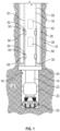
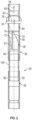
- the first anchor module 312 includes one or more first anchors 316 and the second anchor module 314 includes one or more second anchors 318.
- the anchors 316, 318 can be spaced in an appropriate spacing around the tool axis, also referred to as circumferentially spaced, and in a longitudinal direction, also referred to as axial direction or axially spaced along the length of the liner or running tool (e.g., equally spaced or unequally spaced).
- the first anchor module 312 includes three first anchors 316.
- the second anchor module 314 includes five second anchors 318.
- the anchors 316, 318 of the anchor modules 312, 314 can be configured as blades or other structures as known in the art.
- the anchors 316, 318 are configured to be deployable or expandable to extend outward from an exterior surface of the respective module 312, 314 and engage into a respective liner anchor cavity 308, 310. Further, the anchors 316, 318 are configured to be retractable or closable to pull into the respective module 316, 318, and thus disengage from the respective module 316, 318, which enables or allows movement of the running tool 302 relative to the liner 300.
- FIG. 318 Although shown with particular example numbers of anchors in each anchor module, those of skill in the art will appreciate that any number of anchors can be configured in each of the anchor modules without departing from the scope of the present disclosure.
- the engagement or anchor modules 312, 314 are actuatable or operational such that the anchors or other engagable elements or features are moveable relative to the module.
- anchors of the engagement modules can be electrically, mechanically, hydraulically, or otherwise operated to move the anchor relative to the module (e.g., radially outward from a cylindrical body).
- the engagement modules may be operated by combined methods, such as electro-hydraulically or electro-mechanically.
- an electronics module, electronic components, and/or electronics device(s) can be used to operate the engagement module, including, but not limited to electrically driven hydraulic pumps or motors.
- the electronics device can be an electrical wire, e.g., to transmit a signal, but more sophisticated components and/or modules can be employed without departing from the scope of the present disclosure.
- an electronics module may be the most sophisticated electronic configuration, with electronic components either less sophisticated and/or subparts of an electronics module and an electronic device being the most basic electronic device (e.g., an electrical wire, hydraulic pump, motor, etc.).
- the electronic device can be a single electrical/electronic feature of the system taken alone or may be part of an electronics component and/or part of an electronics module.
- actuation can mean extension from the module into engagement with a surface that is exterior to the module (e.g., an interior surface of a liner) and/or disengagement from such surface. That is, operation/actuation can mean extension or retraction of anchors into or from engagement with a surface or structure.
- the different anchors may be operated separately or collectively. The separate or collective operation can be referred to as dependent or independent operation. In the case of independent operation, for example, only a single anchor may be extended or retracted, or a particular set or number of anchors may be extended or retracted. Further, for example, a particular time-based sequence of particular or predetermined anchor extensions or retractions can be performed in order to engage or disengage with the liner.
- first anchors 316 and the second anchors 318 are selectively extendable into locations on the liner 300 (e.g., liner anchor cavities 308, 310).
- the liner 300 can be configured with repeated configurations of liner anchor cavities 308, 310, which can enable engagement of the running tool 302 with the liner 300 at multiple locations along the length of the liner 300.
- the anchors 316, 318 can latch into engagement with the liner anchor cavities 308, 310 to provide secured contact and engagement between the running tool 302 and the liner 300.
- One advantage enabled by engagement of the running tool 302 at different locations along the length of the liner 300 is to have different extensions of the BHA 306 from the lower end of the liner 300 when drilling a pilot hole as opposed to reaming the pilot hole already drilled.
- the BHA 306 extends out more from the lower end of the liner 300 and so the running tool can be engaged at a lower (e.g., down-hole) position relative to the liner 300 than when a reamer bit is enlarging a pilot hole.
- the anchors 316, 318 are configured to fit in respective liner anchor cavities 308, 310. Pairs of liner anchor cavities 308, 310 are located on the liner 300 at different locations with appropriate spacing relative to each other so that the anchors 316, 318 can be engaged at different locations along the liner 300 and, thus, different extensions of BHA 306 from the lower end of the liner 300 can be achieved.
- each first liner anchor cavity 308 and each second liner anchor cavity 310 of each pair of liner anchor cavities is constant. In other embodiments, the spacing may not be constant. Further, in some embodiments, the shape of a cavity along a length of a string can be different at different positions. Because the running tool 302 can be moved and located at different positions within the liner 300, and such position can be indicative of an extension of the BHA 306, it may be desirable to monitor the position of the running tool 302 within the liner 300.
- the running tool 302 can include one or more electronics modules 319.
- the electronics module 319 can include one or more electronic components, as known in the art, to enable control of the running tool 300, such as determining the engaging and disengaging, and/or enable communication with the surface and/or with other downhole components, including, but not limited to, the BHA 306.
- the electronics module 319 can be part of or form a downlink that enables operation as describe herein. In other configurations, the electronics module 319 can be replaced by an electronics device, such as an electrical wire, that enables transmission of electrical signals to and/or from the running tool 302.
- FIGS. 7A-7B schematic illustrations of a liner 400 having a liner part (e.g., position marker 420) that is part of a position detection system 425 in accordance with an embodiment of the present disclosure are shown.
- a liner part e.g., position marker 420
- FIGS. 7A-7B schematic illustrations of a liner 400 having a liner part (e.g., position marker 420) that is part of a position detection system 425 in accordance with an embodiment of the present disclosure are shown.
- the liner part of the position detection system 425 is a magnetic marker.
- the downhole electronics 419 can be one or more electronic components that are configured in or on the running tool 402, and can be part of an electronics module (e.g., electronics module 319 of FIG. 6A ). In other embodiments, an electronics device (e.g., an electrical wire) can be used instead of the downhole electronics 419.
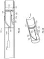
- FIG. 7A is a cross-sectional illustration of a portion of the liner 400 including the position marker 420 in accordance with an embodiment of the present disclosure.
- FIG. 7B is an enlarged illustration of the position marker 420 as indicated by the dashed circle in FIG. 7A .
- the position detection system 425 can be operably connected to or otherwise in communication with downhole electronics 419 of the running tool 402 (e.g., in some embodiments, electronics module 319 of FIG. 6A ).
- the downhole electronics 419 of the running tool 402 can be used to communicate information to the surface, such as the position that is detected by the position detection system 425.
- Properly engaging, disengaging, and moving the running tool 402 relative to the liner 400 is achieved through knowledge of the relative positions of the running tool 402 and the liner 400.
- the anchor modules described above, can be appropriately engaged with corresponding liner anchor cavities at different locations and thus adjustment of an extension of a BHA can be achieved.
- the position detected by the position detection system 425 can be communicated to the surface to inform about the approximate location of the liner anchor cavity pairs relative to respective anchor modules.
- the position marker 420 includes a magnetic ring 422 that has opposed north and south poles 424, 426 as shown. In other embodiments the opposite or differing pole orientation than that shown can be used.
- the magnetic ring 422 in some embodiments, can be a full 360 degrees (e.g., wrap around the liner 400) or, in other embodiments, the magnetic ring 422 can be split such that less than 360 degrees is covered by the magnetic ring 422. Further, in other embodiments, the magnetic ring 422 can have overlapping ends such that the magnetic ring 422 wraps around more than 360 ° of the liner 400. Further still, other configurations can employ spaced magnetic buttons that form the position marker 420.
- the magnetic ring 422 of the position marker 420 creates an easily detected magnetic field that can be detected and/or interact with components or features of the liner or the running tool, depending on the particular configuration.
- position marker 420 as shown in FIGS. 7A-7B e.g., magnetic rings 422
- FIGS. 7A-7B can make the orientation of the running tool 402 in and relative to a liner irrelevant in detection of a signal.
- detection of the location of a liner anchor cavity can be easily achieved, e.g., by another magnetic component located on the liner. Detection can be achieved, in part, by processing carried out on an electronics module, and such detection can be communicated to the surface. Once the detection is communicated to the surface that a magnetic marker is detected, it may be desirable to position the running tool 402 with precision so that extension of the anchors of the first and/or second anchor modules engage within respective liner anchor cavities (as described above).
Landscapes
- Engineering & Computer Science (AREA)
- Geology (AREA)
- Life Sciences & Earth Sciences (AREA)
- Mining & Mineral Resources (AREA)
- Environmental & Geological Engineering (AREA)
- Fluid Mechanics (AREA)
- Physics & Mathematics (AREA)
- General Life Sciences & Earth Sciences (AREA)
- Geochemistry & Mineralogy (AREA)
- Mechanical Engineering (AREA)
- Earth Drilling (AREA)
- Insertion Pins And Rivets (AREA)
- Cutting Tools, Boring Holders, And Turrets (AREA)
- Golf Clubs (AREA)
Claims (6)
- Bohrwerkzeug bei einer Bohrungsarbeit, die in einem Bohrloch durchgeführt wird, umfassend:eine erste Komponente, die eine Längsache aufweist;eine zweite Komponente, die einen Durchgang zum Aufnehmen der ersten Komponente aufweist;einen ersten Anker (52) an der ersten Komponente;einen zweiten Anker (54) an der ersten Komponente;ein erstes Profil (56), das an einer Innenoberfläche (59) ausgebildet ist, die den Durchgang der zweiten Komponente definiert und konfiguriert ist, um den ersten Anker (52) aufzunehmen; undein zweites Profil (58), das an der Innenoberfläche (59) ausgebildet ist, die den Durchgang der zweiten Komponente definiert und konfiguriert ist, um den zweiten Anker (54) aufzunehmen;wobei das erste Profil (56) einen Rampenabschnitt (70) einschließt, wobei der Rampenabschnitt (70) eine Rampenkontur aufweist, die durch eine Rampentangente definiert ist, wobei die Rampentangente einen spitzen Winkel (91) mit der Längsachse ausbildet, wobei der spitze Winkel (91) der Rampentangente größer als 1 Grad und kleiner als 90 Grad ist, wobei der Rampenabschnitt (70) von der Innenoberfläche (59) der zweiten Komponente vorsteht, wobei der vorstehende Rampenabschnitt (70) eine Rampenoberfläche definiert, die radial nach innen vorsteht und konfiguriert ist, um den ersten Anker (52) in eine vorbestimmte Umfangsausrichtung mit der zweiten Komponente zu führen,wobei das erste Profil (56) erste axial ausgerichtete Schultern (72, 81), eine erste in Umfangsrichtung ausgerichtete Schulter (80) und einen ersten Hohlraum umfasst, der konfiguriert ist, um den ersten Anker (52) aufzunehmen, der an der Innenoberfläche (59) ausgebildet ist, wobei der erste Anker (52) konfiguriert ist, um eine Drehmomentbelastung auf eine erste axial ausgerichtete Schulter (72, 81) und eine axiale Belastung auf die erste in Umfangsrichtung ausgerichtete Schulter (80) auszuüben,wobei das zweite Profil (58) eine zweite in Umfangsrichtung ausgerichtete Schulter (90) und einen zweiten Hohlraum umfasst, der konfiguriert ist, um den zweiten Anker (54) aufzunehmen, der an der Innenoberfläche (59) ausgebildet ist, wobei der zweite Anker (54) konfiguriert ist, um eine axiale Belastung auf die zweite in Umfangsrichtung ausgerichtete Schulter (90) auszuüben, undwobei der erste Anker (52) und die erste in Umfangsrichtung ausgerichtete Schulter (80) konfiguriert sind, um die erste und die zweite Komponente derart axial auszurichten, dass das zweite Profil (58) den zweiten Anker (54) aufnehmen kann.
- Bohrwerkzeug nach Anspruch 1, wobei die Rampenkontur durch mindestens eines definiert ist von: (i) einer Kurve, (ii) einer geraden Linie, (iii) einer Vielzahl von unterschiedlichen Kurven, (iv) einer Vielzahl von geraden Linien, die unterschiedliche Neigungen aufweisen, und (v) einer Kombination aus mindestens einer Kurve und mindestens einer geraden Linie.
- Bohrwerkzeug nach Anspruch 1, wobei der erste und/oder der zweite Anker (52, 54) ein sich radial erstreckendes Element umfasst, das eines ist von: (i) fest und (ii) einziehbar.
- Bohrwerkzeug nach Anspruch 1, wobei die erste Komponente ein Bohrstrang (18) ist und die zweite Komponente eine Auskleidungsanordnung (26) ist.
- Bohrwerkzeug nach Anspruch 1, wobei der spitze Winkel (91) kleiner als 50 Grad ist.
- Verfahren zum Durchführen einer Operation in einem Bohrloch unter Verwendung eines Bohrwerkzeugs, das eine erste Komponente, die eine Längsachse aufweist, und eine zweite Komponente aufweist, die einen Durchgang zum Aufnehmen der ersten Komponente aufweist, das Verfahren umfassend:Anordnen eines ersten Ankers (52) an der ersten Komponente;Anordnen eines zweiten Ankers (54) an der ersten Komponente;Ausbilden eines ersten Profils (56) an einer Innenoberfläche (59), die den Durchgang der zweiten Komponente zum Aufnehmen des ersten Ankers (52) definiert; undAusbilden eines zweiten Profils (58) an der Innenoberfläche (59), das den Durchgang der zweiten Komponente zum Aufnehmen des zweiten Ankers (54) definiert;wobei das erste Profil (56) einen Rampenabschnitt (70) einschließt, wobei der Rampenabschnitt (70) eine Rampenkontur aufweist, die durch eine Rampentangente definiert ist, wobei die Rampentangente einen spitzen Winkel (91) mit der Längsachse ausbildet, wobei der spitze Winkel (91) der Rampentangente größer als 1 Grad und kleiner als 90 Grad ist, wobei der Rampenabschnitt (70) von der Innenoberfläche (59) der zweiten Komponente vorsteht, wobei der vorstehende Rampenabschnitt (70) eine Rampenoberfläche definiert, die radial nach innen vorsteht und konfiguriert ist, um den ersten Anker (52) in eine vorbestimmte Umfangsausrichtung mit der zweiten Komponente zu führen;wobei das erste Profil (56) erste axial ausgerichtete Schultern (72, 81), eine erste in Umfangsrichtung ausgerichtete Schulter (80) und einen ersten Hohlraum umfasst, der konfiguriert ist, um den ersten Anker (52) aufzunehmen, der an der Innenoberfläche (59) ausgebildet ist, wobei der erste Anker (52) konfiguriert ist, um eine Drehmomentbelastung auf eine erste axial ausgerichtete Schulter (72, 81) und eine axiale Belastung auf die erste in Umfangsrichtung ausgerichtete Schulter (80) auszuüben,wobei das zweite Profil (58) eine zweite in Umfangsrichtung ausgerichtete Schulter (90) und einen zweiten Hohlraum umfasst, der konfiguriert ist, um den zweiten Anker (54) aufzunehmen, der an der Innenoberfläche (59) ausgebildet ist, wobei der zweite Anker (54) konfiguriert ist, um eine axiale Belastung auf die zweite in Umfangsrichtung ausgerichtete Schulter (90) auszuüben, undwobei der erste Anker (52) und die erste in Umfangsrichtung ausgerichtete Schulter (80) konfiguriert sind, um die erste und die zweite Komponente derart axial auszurichten, dass das zweite Profil (58) den zweiten Anker (54) aufnehmen kann;das Verfahren ferner umfassend:axiales Bewegen der ersten Komponente relativ zu der zweiten Komponente, bis der erste Anker (52) und das erste Profil (56) die erste Komponente und die zweite Komponente in einer vorbestimmten Ausrichtung ausrichten, wobei der erste Anker (52) unter Verwendung des Rampenabschnitts (70) in eine vorbestimmte Umfangsausrichtung mit der zweiten Komponente geführt wird und der erste Anker (52) und die erste in Umfangsrichtung ausgerichtete Schulter (80) die erste und die zweite Komponente derart axial ausrichten, dass das zweite Profil (58) den zweiten Anker (54) aufnehmen kann; undAufbringen einer Drehmomentbelastung auf eine erste axial ausgerichtete Schulter (72, 81) unter Verwendung des ersten Ankers (52), Aufbringen einer axialen Belastung auf die erste in Umfangsrichtung ausgerichtete Schulter (80) unter Verwendung des ersten Ankers (52) oder Aufbringen einer axialen Belastung auf die zweite in Umfangsrichtung ausgerichtete Schulter (90) unter Verwendung des zweiten Ankers (54).
Applications Claiming Priority (2)
| Application Number | Priority Date | Filing Date | Title |
|---|---|---|---|
| US15/604,124 US11952842B2 (en) | 2017-05-24 | 2017-05-24 | Sophisticated contour for downhole tools |
| PCT/US2018/034426 WO2018218043A1 (en) | 2017-05-24 | 2018-05-24 | Sophisticated contour for downhole tools |
Publications (3)
| Publication Number | Publication Date |
|---|---|
| EP3631148A1 EP3631148A1 (de) | 2020-04-08 |
| EP3631148A4 EP3631148A4 (de) | 2021-03-17 |
| EP3631148B1 true EP3631148B1 (de) | 2025-06-25 |
Family
ID=64397062
Family Applications (1)
| Application Number | Title | Priority Date | Filing Date |
|---|---|---|---|
| EP18806172.5A Active EP3631148B1 (de) | 2017-05-24 | 2018-05-24 | Ausgeklügelte kontur für bohrlochwerkzeuge |
Country Status (4)
| Country | Link |
|---|---|
| US (1) | US11952842B2 (de) |
| EP (1) | EP3631148B1 (de) |
| CA (1) | CA3064440A1 (de) |
| WO (1) | WO2018218043A1 (de) |
Families Citing this family (6)
| Publication number | Priority date | Publication date | Assignee | Title |
|---|---|---|---|---|
| US11713117B2 (en) * | 2020-03-31 | 2023-08-01 | Cnh Industrial America Llc | System and method for anchoring unmanned aerial vehicles to surfaces |
| NO346502B1 (en) * | 2020-06-25 | 2022-09-12 | Target Intervention As | Downhole tool and method for operating the same |
| CA3232408A1 (en) * | 2021-11-10 | 2023-05-19 | Halliburton Energy Services, Inc. | Debris resistant keyed running tool and method |
| US12209463B2 (en) * | 2023-05-30 | 2025-01-28 | Saudi Arabian Oil Company | Method and apparatus for retrieving tubing using disconnectable sub in a wellbore |
| US12352114B2 (en) | 2023-06-19 | 2025-07-08 | Halliburton Energy Services, Inc. | No-rotation latch coupling and latch for casing assemblies |
| US12612834B2 (en) * | 2023-11-30 | 2026-04-28 | Halliburton Energy Services, Inc. | Downhole orienting helix for operations requiring multiple orienting sequences |
Citations (1)
| Publication number | Priority date | Publication date | Assignee | Title |
|---|---|---|---|---|
| EP0834643B1 (de) * | 1996-10-01 | 2007-03-28 | Anadrill International SA | Verfahren und Vorrichtung zum Bohren von und zum Wiedereinfahren in Lateralbohrungen |
Family Cites Families (38)
| Publication number | Priority date | Publication date | Assignee | Title |
|---|---|---|---|---|
| US3598183A (en) * | 1969-09-29 | 1971-08-10 | Byron Jackson Inc | Method and apparatus for treating wells |
| US5129453A (en) * | 1990-09-28 | 1992-07-14 | Dresser Industries, Inc. | Quick set well packer |
| US5579829A (en) | 1995-06-29 | 1996-12-03 | Baroid Technology, Inc. | Keyless latch for orienting and anchoring downhole tools |
| US5785357A (en) | 1995-09-22 | 1998-07-28 | Utd, Inc. | Locking joint |
| US5950744A (en) | 1997-10-14 | 1999-09-14 | Hughes; W. James | Method and apparatus for aligning drill pipe and tubing |
| CA2248287C (en) * | 1998-09-22 | 2002-05-21 | Laurier E. Comeau | Fail-safe coupling for a latch assembly |
| US6702040B1 (en) | 2001-04-26 | 2004-03-09 | Floyd R. Sensenig | Telescopic drilling method |
| US7240738B2 (en) * | 2003-01-28 | 2007-07-10 | Baker Hughes Incorporated | Self-orienting selectable locating collet and method for location within a wellbore |
| US7360594B2 (en) * | 2003-03-05 | 2008-04-22 | Weatherford/Lamb, Inc. | Drilling with casing latch |
| US7390032B2 (en) | 2003-08-01 | 2008-06-24 | Sonstone Corporation | Tubing joint of multiple orientations containing electrical wiring |
| US7757784B2 (en) * | 2003-11-17 | 2010-07-20 | Baker Hughes Incorporated | Drilling methods utilizing independently deployable multiple tubular strings |
| US7182153B2 (en) | 2004-01-09 | 2007-02-27 | Schlumberger Technology Corporation | Methods of casing drilling |
| US7299880B2 (en) | 2004-07-16 | 2007-11-27 | Weatherford/Lamb, Inc. | Surge reduction bypass valve |
| CA2644442C (en) | 2006-03-02 | 2013-04-23 | Baker Hughes Incorporated | Automated steerable hole enlargement drilling device and methods |
| SG143232A1 (en) | 2006-12-06 | 2008-06-27 | Vetco Gray Inc | Method for running casing while drilling system |
| US7926578B2 (en) * | 2007-10-03 | 2011-04-19 | Tesco Corporation | Liner drilling system and method of liner drilling with retrievable bottom hole assembly |
| US7926590B2 (en) * | 2007-10-03 | 2011-04-19 | Tesco Corporation | Method of liner drilling and cementing utilizing a concentric inner string |
| EP2065554B1 (de) | 2007-11-30 | 2014-04-02 | Services Pétroliers Schlumberger | System und Verfahren zum Bohren und Abschließen seitlicher Bohrlöcher |
| US7845431B2 (en) | 2008-05-22 | 2010-12-07 | Tesco Corporation | Retrieval tool with slips for retrieving bottom hole assembly during casing while drilling operations |
| US7708077B2 (en) | 2008-05-22 | 2010-05-04 | Tesco Corporation | Retrieval of bottom hole assembly during casing while drilling operations |
| US20150176341A1 (en) * | 2010-01-28 | 2015-06-25 | Sunstone Technologies, Llc | Tapered Spline Connection for Drill Pipe, Casing, and Tubing |
| EP2691595B1 (de) * | 2011-03-26 | 2020-04-01 | Halliburton Energy Services, Inc. | Einweg-futterkonfiguration und bohrvorrichtung |
| US9394763B2 (en) * | 2011-08-08 | 2016-07-19 | Schlumberger Technology Corporation | Multilateral location and orientation assembly |
| EP2557265A1 (de) | 2011-08-10 | 2013-02-13 | Geoservices Equipements | Vorrichtung zur Extraktion von mindestens einem Gas aus einer zirkulierenden Flüssigkeit |
| CA2960257C (en) * | 2012-04-30 | 2018-12-04 | Halliburton Energy Services, Inc. | Wellbore casing section with moveable portion for providing a casing exit |
| US9004195B2 (en) * | 2012-08-22 | 2015-04-14 | Baker Hughes Incorporated | Apparatus and method for drilling a wellbore, setting a liner and cementing the wellbore during a single trip |
| MY181705A (en) * | 2012-09-06 | 2021-01-04 | Reform Energy Services Corp | Latching assembly |
| US9316074B2 (en) * | 2012-11-27 | 2016-04-19 | Baker Hughes Incorporated | Resettable selective locking device |
| US9518441B2 (en) * | 2013-05-07 | 2016-12-13 | Freudenberg Oil & Gas, Llc | Expandable packing element and cartridge |
| CA2929370C (en) | 2013-12-05 | 2017-10-10 | Halliburton Energy Services, Inc. | Directional casing-while-drilling |
| WO2015105487A1 (en) * | 2014-01-08 | 2015-07-16 | Halliburton Energy Services, Inc. | Running tool and liner hanger contingency release mechanism |
| WO2015109147A1 (en) * | 2014-01-20 | 2015-07-23 | Schlumberger Canada Limited | One trip liner drilling and cementing |
| US9453393B2 (en) * | 2014-01-22 | 2016-09-27 | Seminole Services, LLC | Apparatus and method for setting a liner |
| CA2958465C (en) * | 2014-10-08 | 2019-02-26 | Halliburton Energy Services, Inc. | Liner drilling using retrievable bottom-hole assembly |
| US10711527B2 (en) | 2015-07-27 | 2020-07-14 | Halliburton Energy Services, Inc. | Drill bit and method for casing while drilling |
| NO20161103A1 (en) * | 2015-10-14 | 2017-04-17 | Comitt Well Solutions Us Holding Inc | Positioning system |
| WO2017171853A1 (en) * | 2016-04-01 | 2017-10-05 | Halliburton Energy Services, Inc. | Latch assembly using on-board miniature hydraulics for rcd applications |
| US10329861B2 (en) * | 2016-09-27 | 2019-06-25 | Baker Hughes, A Ge Company, Llc | Liner running tool and anchor systems and methods |
-
2017
- 2017-05-24 US US15/604,124 patent/US11952842B2/en active Active
-
2018
- 2018-05-24 EP EP18806172.5A patent/EP3631148B1/de active Active
- 2018-05-24 WO PCT/US2018/034426 patent/WO2018218043A1/en not_active Ceased
- 2018-05-24 CA CA3064440A patent/CA3064440A1/en not_active Abandoned
Patent Citations (1)
| Publication number | Priority date | Publication date | Assignee | Title |
|---|---|---|---|---|
| EP0834643B1 (de) * | 1996-10-01 | 2007-03-28 | Anadrill International SA | Verfahren und Vorrichtung zum Bohren von und zum Wiedereinfahren in Lateralbohrungen |
Also Published As
| Publication number | Publication date |
|---|---|
| EP3631148A4 (de) | 2021-03-17 |
| EP3631148A1 (de) | 2020-04-08 |
| WO2018218043A1 (en) | 2018-11-29 |
| CA3064440A1 (en) | 2018-11-29 |
| BR112019024600A2 (pt) | 2020-06-09 |
| US20180340377A1 (en) | 2018-11-29 |
| US11952842B2 (en) | 2024-04-09 |
Similar Documents
| Publication | Publication Date | Title |
|---|---|---|
| EP3631148B1 (de) | Ausgeklügelte kontur für bohrlochwerkzeuge | |
| EP3631141B1 (de) | Vorrichtung und verfahren zum austausch von signalen / energie zwischen einem innen- und einem aussenrohr | |
| US10731417B2 (en) | Reduced trip well system for multilateral wells | |
| EP2888431B1 (de) | Vorrichtung und verfahren zum bohren eines bohrlochs, abbinden einer auskleidung und zementieren des bohrlochs in einem | |
| CA2661169C (en) | Releasing and recovering tool | |
| EP3519664B1 (de) | Auskleidungslaufwerkzeug und ankersysteme und -verfahren | |
| CN104903536B (zh) | 用于旋转地定向造斜器组件的系统和方法 | |
| NO349662B1 (en) | Inner and outer downhole structures having downlink activation | |
| US20150144401A1 (en) | Hydraulically actuated tool with electrical throughbore | |
| EP3485134B1 (de) | Anordnung zur rückflussverhinderung für bohrlochoperationen | |
| CA2895787C (en) | Apparatus and methods of running casing | |
| CA2879085C (en) | Pipe in pipe piston thrust system | |
| BR112019024600B1 (pt) | Ferramenta de poço em uma operação de poço e método para executar uma operação em um poço usando uma ferramenta de poço | |
| BR112019024073B1 (pt) | Ferramenta de poço em uma operação de poço em um poço e método para executar uma operação usando uma ferramenta de poço que tem um primeiro componente e um segundo componente |
Legal Events
| Date | Code | Title | Description |
|---|---|---|---|
| STAA | Information on the status of an ep patent application or granted ep patent |
Free format text: STATUS: THE INTERNATIONAL PUBLICATION HAS BEEN MADE |
|
| PUAI | Public reference made under article 153(3) epc to a published international application that has entered the european phase |
Free format text: ORIGINAL CODE: 0009012 |
|
| STAA | Information on the status of an ep patent application or granted ep patent |
Free format text: STATUS: REQUEST FOR EXAMINATION WAS MADE |
|
| 17P | Request for examination filed |
Effective date: 20191222 |
|
| AK | Designated contracting states |
Kind code of ref document: A1 Designated state(s): AL AT BE BG CH CY CZ DE DK EE ES FI FR GB GR HR HU IE IS IT LI LT LU LV MC MK MT NL NO PL PT RO RS SE SI SK SM TR |
|
| AX | Request for extension of the european patent |
Extension state: BA ME |
|
| RIN1 | Information on inventor provided before grant (corrected) |
Inventor name: MELLES, HENNING Inventor name: EGGERS, HEIKO |
|
| DAV | Request for validation of the european patent (deleted) | ||
| DAX | Request for extension of the european patent (deleted) | ||
| A4 | Supplementary search report drawn up and despatched |
Effective date: 20210212 |
|
| RIC1 | Information provided on ipc code assigned before grant |
Ipc: E21B 17/02 20060101ALI20210208BHEP Ipc: E21B 23/01 20060101AFI20210208BHEP Ipc: E21B 7/20 20060101ALI20210208BHEP |
|
| STAA | Information on the status of an ep patent application or granted ep patent |
Free format text: STATUS: EXAMINATION IS IN PROGRESS |
|
| 17Q | First examination report despatched |
Effective date: 20230117 |
|
| P01 | Opt-out of the competence of the unified patent court (upc) registered |
Effective date: 20230526 |
|
| GRAP | Despatch of communication of intention to grant a patent |
Free format text: ORIGINAL CODE: EPIDOSNIGR1 |
|
| STAA | Information on the status of an ep patent application or granted ep patent |
Free format text: STATUS: GRANT OF PATENT IS INTENDED |
|
| INTG | Intention to grant announced |
Effective date: 20250328 |
|
| GRAS | Grant fee paid |
Free format text: ORIGINAL CODE: EPIDOSNIGR3 |
|
| GRAA | (expected) grant |
Free format text: ORIGINAL CODE: 0009210 |
|
| STAA | Information on the status of an ep patent application or granted ep patent |
Free format text: STATUS: THE PATENT HAS BEEN GRANTED |
|
| RAP3 | Party data changed (applicant data changed or rights of an application transferred) |
Owner name: BAKER HUGHES HOLDINGS LLC |
|
| AK | Designated contracting states |
Kind code of ref document: B1 Designated state(s): AL AT BE BG CH CY CZ DE DK EE ES FI FR GB GR HR HU IE IS IT LI LT LU LV MC MK MT NL NO PL PT RO RS SE SI SK SM TR |
|
| REG | Reference to a national code |
Ref country code: GB Ref legal event code: FG4D |
|
| REG | Reference to a national code |
Ref country code: CH Ref legal event code: EP |
|
| REG | Reference to a national code |
Ref country code: DE Ref legal event code: R096 Ref document number: 602018082962 Country of ref document: DE |
|
| REG | Reference to a national code |
Ref country code: CH Ref legal event code: EP |
|
| REG | Reference to a national code |
Ref country code: IE Ref legal event code: FG4D |
|
| PG25 | Lapsed in a contracting state [announced via postgrant information from national office to epo] |
Ref country code: FI Free format text: LAPSE BECAUSE OF FAILURE TO SUBMIT A TRANSLATION OF THE DESCRIPTION OR TO PAY THE FEE WITHIN THE PRESCRIBED TIME-LIMIT Effective date: 20250625 |
|
| REG | Reference to a national code |
Ref country code: LT Ref legal event code: MG9D |
|
| PG25 | Lapsed in a contracting state [announced via postgrant information from national office to epo] |
Ref country code: GR Free format text: LAPSE BECAUSE OF FAILURE TO SUBMIT A TRANSLATION OF THE DESCRIPTION OR TO PAY THE FEE WITHIN THE PRESCRIBED TIME-LIMIT Effective date: 20250926 |
|
| PG25 | Lapsed in a contracting state [announced via postgrant information from national office to epo] |
Ref country code: BG Free format text: LAPSE BECAUSE OF FAILURE TO SUBMIT A TRANSLATION OF THE DESCRIPTION OR TO PAY THE FEE WITHIN THE PRESCRIBED TIME-LIMIT Effective date: 20250625 |
|
| PG25 | Lapsed in a contracting state [announced via postgrant information from national office to epo] |
Ref country code: HR Free format text: LAPSE BECAUSE OF FAILURE TO SUBMIT A TRANSLATION OF THE DESCRIPTION OR TO PAY THE FEE WITHIN THE PRESCRIBED TIME-LIMIT Effective date: 20250625 |
|
| PG25 | Lapsed in a contracting state [announced via postgrant information from national office to epo] |
Ref country code: RS Free format text: LAPSE BECAUSE OF FAILURE TO SUBMIT A TRANSLATION OF THE DESCRIPTION OR TO PAY THE FEE WITHIN THE PRESCRIBED TIME-LIMIT Effective date: 20250925 |
|
| PG25 | Lapsed in a contracting state [announced via postgrant information from national office to epo] |
Ref country code: LV Free format text: LAPSE BECAUSE OF FAILURE TO SUBMIT A TRANSLATION OF THE DESCRIPTION OR TO PAY THE FEE WITHIN THE PRESCRIBED TIME-LIMIT Effective date: 20250625 |
|
| REG | Reference to a national code |
Ref country code: NL Ref legal event code: MP Effective date: 20250625 |
|
| PG25 | Lapsed in a contracting state [announced via postgrant information from national office to epo] |
Ref country code: NL Free format text: LAPSE BECAUSE OF FAILURE TO SUBMIT A TRANSLATION OF THE DESCRIPTION OR TO PAY THE FEE WITHIN THE PRESCRIBED TIME-LIMIT Effective date: 20250625 |
|
| PG25 | Lapsed in a contracting state [announced via postgrant information from national office to epo] |
Ref country code: PT Free format text: LAPSE BECAUSE OF FAILURE TO SUBMIT A TRANSLATION OF THE DESCRIPTION OR TO PAY THE FEE WITHIN THE PRESCRIBED TIME-LIMIT Effective date: 20251027 |
|
| REG | Reference to a national code |
Ref country code: AT Ref legal event code: MK05 Ref document number: 1806615 Country of ref document: AT Kind code of ref document: T Effective date: 20250625 |
|
| PG25 | Lapsed in a contracting state [announced via postgrant information from national office to epo] |
Ref country code: IS Free format text: LAPSE BECAUSE OF FAILURE TO SUBMIT A TRANSLATION OF THE DESCRIPTION OR TO PAY THE FEE WITHIN THE PRESCRIBED TIME-LIMIT Effective date: 20251025 |
|
| PG25 | Lapsed in a contracting state [announced via postgrant information from national office to epo] |
Ref country code: AT Free format text: LAPSE BECAUSE OF FAILURE TO SUBMIT A TRANSLATION OF THE DESCRIPTION OR TO PAY THE FEE WITHIN THE PRESCRIBED TIME-LIMIT Effective date: 20250625 Ref country code: SM Free format text: LAPSE BECAUSE OF FAILURE TO SUBMIT A TRANSLATION OF THE DESCRIPTION OR TO PAY THE FEE WITHIN THE PRESCRIBED TIME-LIMIT Effective date: 20250625 |
|
| PG25 | Lapsed in a contracting state [announced via postgrant information from national office to epo] |
Ref country code: CZ Free format text: LAPSE BECAUSE OF FAILURE TO SUBMIT A TRANSLATION OF THE DESCRIPTION OR TO PAY THE FEE WITHIN THE PRESCRIBED TIME-LIMIT Effective date: 20250625 |
|
| PG25 | Lapsed in a contracting state [announced via postgrant information from national office to epo] |
Ref country code: PL Free format text: LAPSE BECAUSE OF FAILURE TO SUBMIT A TRANSLATION OF THE DESCRIPTION OR TO PAY THE FEE WITHIN THE PRESCRIBED TIME-LIMIT Effective date: 20250625 |
|
| PG25 | Lapsed in a contracting state [announced via postgrant information from national office to epo] |
Ref country code: EE Free format text: LAPSE BECAUSE OF FAILURE TO SUBMIT A TRANSLATION OF THE DESCRIPTION OR TO PAY THE FEE WITHIN THE PRESCRIBED TIME-LIMIT Effective date: 20250625 |
|
| PG25 | Lapsed in a contracting state [announced via postgrant information from national office to epo] |
Ref country code: SK Free format text: LAPSE BECAUSE OF FAILURE TO SUBMIT A TRANSLATION OF THE DESCRIPTION OR TO PAY THE FEE WITHIN THE PRESCRIBED TIME-LIMIT Effective date: 20250625 |
|
| PG25 | Lapsed in a contracting state [announced via postgrant information from national office to epo] |
Ref country code: ES Free format text: LAPSE BECAUSE OF FAILURE TO SUBMIT A TRANSLATION OF THE DESCRIPTION OR TO PAY THE FEE WITHIN THE PRESCRIBED TIME-LIMIT Effective date: 20250625 |
|
| PG25 | Lapsed in a contracting state [announced via postgrant information from national office to epo] |
Ref country code: DK Free format text: LAPSE BECAUSE OF FAILURE TO SUBMIT A TRANSLATION OF THE DESCRIPTION OR TO PAY THE FEE WITHIN THE PRESCRIBED TIME-LIMIT Effective date: 20250625 |
|
| PG25 | Lapsed in a contracting state [announced via postgrant information from national office to epo] |
Ref country code: IT Free format text: LAPSE BECAUSE OF FAILURE TO SUBMIT A TRANSLATION OF THE DESCRIPTION OR TO PAY THE FEE WITHIN THE PRESCRIBED TIME-LIMIT Effective date: 20250625 |
|
| PLBE | No opposition filed within time limit |
Free format text: ORIGINAL CODE: 0009261 |
|
| STAA | Information on the status of an ep patent application or granted ep patent |
Free format text: STATUS: NO OPPOSITION FILED WITHIN TIME LIMIT |