EP3631162B1 - Verfahren und systeme zur bohrlochmessung und kommunikation in bohrlöchern - Google Patents
Verfahren und systeme zur bohrlochmessung und kommunikation in bohrlöchern Download PDFInfo
- Publication number
- EP3631162B1 EP3631162B1 EP18809046.8A EP18809046A EP3631162B1 EP 3631162 B1 EP3631162 B1 EP 3631162B1 EP 18809046 A EP18809046 A EP 18809046A EP 3631162 B1 EP3631162 B1 EP 3631162B1
- Authority
- EP
- European Patent Office
- Prior art keywords
- tubing
- production
- encapsulated
- sensor
- casing
- Prior art date
- Legal status (The legal status is an assumption and is not a legal conclusion. Google has not performed a legal analysis and makes no representation as to the accuracy of the status listed.)
- Active
Links
Images



Classifications
-
- E—FIXED CONSTRUCTIONS
- E21—EARTH OR ROCK DRILLING; MINING
- E21B—EARTH OR ROCK DRILLING; OBTAINING OIL, GAS, WATER, SOLUBLE OR MELTABLE MATERIALS OR A SLURRY OF MINERALS FROM WELLS
- E21B47/00—Survey of boreholes or wells
- E21B47/12—Means for transmitting measuring-signals or control signals from the well to the surface, or from the surface to the well, e.g. for logging while drilling
- E21B47/13—Means for transmitting measuring-signals or control signals from the well to the surface, or from the surface to the well, e.g. for logging while drilling by electromagnetic energy, e.g. radio frequency
-
- H—ELECTRICITY
- H04—ELECTRIC COMMUNICATION TECHNIQUE
- H04B—TRANSMISSION
- H04B13/00—Transmission systems characterised by the medium used for transmission, not provided for in groups H04B3/00 - H04B11/00
-
- E—FIXED CONSTRUCTIONS
- E21—EARTH OR ROCK DRILLING; MINING
- E21B—EARTH OR ROCK DRILLING; OBTAINING OIL, GAS, WATER, SOLUBLE OR MELTABLE MATERIALS OR A SLURRY OF MINERALS FROM WELLS
- E21B17/00—Drilling rods or pipes; Flexible drill strings; Kellies; Drill collars; Sucker rods; Cables; Casings; Tubings
- E21B17/003—Drilling rods or pipes; Flexible drill strings; Kellies; Drill collars; Sucker rods; Cables; Casings; Tubings with electrically conducting or insulating means
-
- E—FIXED CONSTRUCTIONS
- E21—EARTH OR ROCK DRILLING; MINING
- E21B—EARTH OR ROCK DRILLING; OBTAINING OIL, GAS, WATER, SOLUBLE OR MELTABLE MATERIALS OR A SLURRY OF MINERALS FROM WELLS
- E21B43/00—Methods or apparatus for obtaining oil, gas, water, soluble or meltable materials or a slurry of minerals from wells
- E21B43/12—Methods or apparatus for controlling the flow of the obtained fluid to or in wells
- E21B43/121—Lifting well fluids
- E21B43/122—Gas lift
-
- E—FIXED CONSTRUCTIONS
- E21—EARTH OR ROCK DRILLING; MINING
- E21B—EARTH OR ROCK DRILLING; OBTAINING OIL, GAS, WATER, SOLUBLE OR MELTABLE MATERIALS OR A SLURRY OF MINERALS FROM WELLS
- E21B47/00—Survey of boreholes or wells
- E21B47/10—Locating fluid leaks, intrusions or movements
- E21B47/103—Locating fluid leaks, intrusions or movements using thermal measurements
Definitions
- the field of the invention relates generally to production wells, and more specifically, to methods and systems for downhole sensing and communications in a production well.
- US 2006/124318 A1 discloses providing telemetry between a downhole device located in a wellbore and an up-hole device.
- downhole sensing equipment e.g., temperature and pressure sensors
- At least some known production wells use one or more cables that extend from the surface through the production well to the downhole sensing equipment.
- the cables supply power to the downhole sensing equipment and/or provide communication between the downhole sensing equipment and the surface.
- at least some known cables increase the cost to assemble the production well and reduce the space available for other components in the production well (e.g., pipes, conduits, mandrels, etc.). Accordingly, it is desirable to wirelessly provide power and communications between surface equipment and downhole sensing equipment in a production well.
- the systems and methods described herein provide power and communications for downhole sensing equipment. These methods and systems use tubing to transmit power to downhole sensing equipment, and provide wireless communication between surface equipment and the downhole sensing equipment.
- encapsulated tubing provides a current flow path between the surface equipment and the downhole sensing equipment.
- production tubing acts a ground to provide a return path for the electrical current.
- the electrical current provides power to the downhole sensing equipment and enables the transmission of signals between the surface equipment and the downhole sensing equipment. Accordingly, the systems and methods provide wireless power and communications between downhole components and the surface, and eliminate the need to run power and communication cables down through a well.
- FIG. 1 is a schematic diagram of an exemplary production system 100.
- Production system 100 includes an artificial lift system 102 and a well 104.
- well 104 is a hole drilled for extracting production fluid 110, such as crude oil, water, and/or gas, from the ground.
- Artificial lift system 102 is configured to facilitate extracting fluid through well 104.
- a fluid such as gas is injected into well 104 and proceeds downhole.
- Artificial lift system 102 includes an injection control valve 105 which regulates a quantity of fluid injected into well 104. While the fluid is being injected, an injection temperature sensor 106, an injection pressure sensor 108, and an injection meter 109 take measurements at the surface.
- artificial lift system 102 has any configuration that enables production system 100 to operate as described herein.
- artificial lift system 102 is configured to inject any fluid including, without limitation, chemicals, gas, liquids, and/or fuel.
- artificial lift system 102 is omitted.
- a flow tube pressure sensor 118 measures the wellhead tubing pressure.
- a flow line 120 channels fluids 110 to a separator 122.
- Separator 122 separates fluid 110 into gas 124, oil 126, and water 128.
- Oil 126 is removed by separator 122 and the amount of oil retrieved is metered by oil meter 130.
- Water 128 is also removed by separator 122 and the amount of water retrieved is metered by water meter 132.
- Gas 124 is siphoned out of separator 122 through gas line 134.
- multi-phase flow meter 136 replaces oil meter 130 and water meter 132.
- a multi-phase flow meter 136 is used to measure production.
- Some gas 124 is transferred to a gas pipeline 140 through a gas production meter 138.
- some gas 124 is transferred to a compressor 148 though a flow line 146.
- compressor 148 includes a compressor engine 150.
- Compressor 148 compresses gas 124
- a compressor controller 152 regulates the speed of compressor engine 150.
- compressor 148 is driven by gas or electricity.
- the speed of compressor engine 150 is measured in regulating the revolutions per minute (RPM) of compressor engine 150.
- a compressor back pressure valve 156 ensures sufficient discharge pressure for the well and recycles excessive gas back to the compressor suction valve 154.
- a compressor recycle valve 158 is an overflow valve that reintroduces gas 124 above a certain pressure back into compressor 148 through compressor suction valve 154.
- Gas 124 flows from compressor 148 to well 104. The amount of gas that is injected into well 104 is measured by injection meter 109.
- gas 124 is compressed by compressor 148.
- the amount of gas 124 injected into well 104 is controlled by injection control valve 105 and measured by injection meter 109.
- gas 124 mixes with fluids 110.
- the mixture of fluids 110 and gas 124 is pushed up through tubing 114 to the top of well 104 by reservoir pressure 112.
- the mixture of gas 124 and fluids 110 travels through flow line 120 into separator 122, where fluids 110 and gas 124 are separated.
- a quantity of gas 124 is routed back to compressor 148 to be reinjected into well 104.
- Excess gas 124 is routed to gas pipeline 140 to be sold or otherwise used elsewhere. In some embodiments, some gas 124 is used to power compressor engine 150.
- production system 100 includes a controller 160 installed at the surface of production system 100.
- Controller 160 receives signals from one or more downhole communication or telemetry systems located in well 104, as described herein. Controller 160 processes the received signals (e.g., by decrypting or converting the information therein) and generates one or more outputs based on the processed signals. The outputs may, for example, cause information to be displayed on a display device 162 communicatively coupled to controller 160 for viewing by a human operator.
- a power supply 164 is coupled to controller 160.
- power supply 164 is wirelessly coupled to sensors 117.
- Power supply 164 provides electrical current to controller 160, sensors 117, and/or other components of production system 100.
- power supply 164 provides direct current and/or alternating current.
- power supply 164 provides 110 Volt, 220 Volt, and 440 Volt alternating current.
- power supply 164 provides any power that enables well 200 to operate as described herein
- FIG. 2 is a schematic diagram of a portion of an exemplary well 200, such as well 104 (shown in FIG. 1 ).
- FIG. 3 is a cross-section of well 200 taken along section line 3-3.
- Well 200 includes production tubing 202, such as tubing 114 (shown in FIG. 1 ), that extends through a casing 204.
- An annulus 206 is defined between production tubing 202 and casing 204.
- well 200 includes encapsulated tubing 208 located within production tubing 202.
- encapsulated tubing 208 is located within annulus 206 between production tubing 202 and casing 204.
- production tubing 202 and encapsulated tubing 208 are configured to channel fluids.
- Production tubing 202 has a first diameter and is configured to channel fluids 110 (shown in FIG. 1 ) upwards through casing 204 towards a wellhead.
- Encapsulated tubing 208 has a second diameter less than the first diameter and is configured to channel fluids downhole in well 104.
- Encapsulated tubing 208 includes a discharge port 210 configured to discharge the fluids.
- artificial lift system 102 (shown in FIG. 1 ) is configured to direct injection fluids through a capillary string including encapsulated tubing 208 and encapsulated tubing 208 discharges the injection fluids downhole into well 200.
- well 200 includes any tubing that enables well 200 to operate as described herein.
- encapsulated tubing 208 is configured to channel fluids 110 (shown in FIG. 1 ) towards the wellhead.
- well 200 includes a downhole tool 212.
- Downhole tool 212 includes at least one sensor 214 and a communications device 216.
- Downhole tool 212 is coupled to an end of encapsulated tubing 208 and is positioned in casing 204.
- casing 204 includes positioning features such as a landing nipple and landing tool 218 to locate downhole tool 212.
- Communications device 216 is configured to communicate with controller 160 (shown in FIG. 1 ).
- well 200 includes any downhole tool that enables well 200 to operate as described herein.
- sensor 214 is configured to detect downhole conditions within casing 204.
- sensor 214 includes, without limitation, pressure sensors, temperature sensors, position determination sensors (e.g., ultrasonic sensors), accelerometers, flow sensors (e.g., acoustic flow sensors), fluid property sensors, conductivity sensors, salinity sensors, microwave water-cut sensors, vortex flow sensors, nuclear densometers, etc.
- well 200 includes any sensor 214 that enables well 200 to operate as described herein.
- sensor 214 includes a pressure sensor in communication with a pressure port to facilitate measuring, for example, a pressure within a gas lift mandrel 220 and/or production tubing 202.
- encapsulated tubing 208 includes a conductive sidewall 222 and an insulative layer 224.
- Conductive sidewall 222 is cylindrical and defines a channel 225 for injection fluid.
- Conductive sidewall 222 includes a conductive material and is configured to conduct electrical current to sensors 214.
- conductive sidewall 222 is constructed of a metal such as stainless steel and/or Inconel. Accordingly, encapsulated tubing 208 acts as a mono-conductor. In alternative embodiments, encapsulated tubing 208 includes any conductive sidewall 222 that enables well 200 to operate as described herein.
- production tubing 202 includes a conductive material.
- production tubing 202 is constructed of metals such as steel. Accordingly, production tubing 202 acts as ground tubing and is configured to conduct electrical current from sensors 214 towards the wellhead.
- insulative layer 224 surrounds conductive sidewall 222 and is configured to inhibit electrical current from discharging to conductive components within casing 204 during operation of well 200 when electrical current is flowing through conductive sidewall 222 and/or production tubing 202.
- insulative layer 224 is constructed of non-conductive or electrically insulative materials such as plastics (e.g., nylon and polytetrafluoroethylene (PTFE).
- PTFE polytetrafluoroethylene
- insulative layer 224 is a coating on conductive sidewall 222.
- encapsulated tubing 208 includes any insulative layer 224 that enables encapsulated tubing 208 to function as described herein.
- a portion of conductive sidewall 222 extends beyond insulative layer 224 and couples to downhole tool 212. Specifically, an end of conductive sidewall 222 extends beyond insulative layer 224 and is in contact with power electronics and/or communication device 216 of downhole tool 212.
- encapsulated tubing 208 and sensor 214 are coupled in any manner that enables well 200 to operate as described herein.
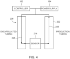
- FIG. 4 is a schematic diagram of current flow in the production well 200.
- Encapsulated tubing 208 and production tubing 202 define a current flow path 226 between sensor 214 and power supply 164.
- encapsulated tubing 208 is coupled to power supply 164 and sensor 214 and conveys electrical power from power supply 164 to sensor 214.
- Sensor 214 is configured to operate using the electrical power received from power supply 164.
- Production tubing 202 acts as ground tubing to provide a return path 228 for the electrical current.
- encapsulated tubing 208 and production tubing 202 transfer signals between sensor 214 and controller 160. Accordingly, encapsulated tubing 208 and production tubing 202 eliminate the need for one or more cables in well 200 to provide power to downhole equipment, and to provide communications between downhole equipment and the surface.
- controller 160 is configured to regulate flow of an electrical current through conductive sidewall 222. Accordingly, controller 160 regulates the power supplied to sensors 214. In addition, controller 160 (shown in FIG. 1 ) regulates the electrical current to communicate using encapsulated tubing 208. For example, in some embodiments, controller 160 (shown in FIG. 1 ) is configured to send signals through encapsulated tubing 208 to sensor 214. In addition, controller 160 is configured to monitor the electric current transferred through encapsulated tubing 208 and/or production tubing 202 and receive signals sent through encapsulated tubing 208 and/or production tubing 202 from sensor 214 and/or other components of well 200.
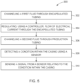
- FIG. 5 is a flow diagram of an exemplary method 300 of sensing downhole conditions of production well 200.
- method 300 generally includes channeling 302 an injection fluid through encapsulated tubing 208, regulating 304 flow of electrical current through conductive sidewall 222, channeling 306 a production fluid through production tubing 202, detecting 308 a condition within casing 204 using sensor 214, and sending 310 a signal relating to the condition.
- channeling 302 includes channeling the injection fluid from the wellhead downhole through encapsulated tubing 208.
- the injection fluid is used to facilitate operation of well 200.
- injection fluid is directed from a capillary string including encapsulated tubing 208.
- the injection fluid is directed along casing 204 to remediate deposition on casing 204, reduce the formation of scale on casing 204, and/or remove material or bridging extending across casing 204.
- encapsulated tubing 208 is used to channel any fluid that enables well 200 to operate as described herein.
- artificial lift system 102 (shown in FIG. 1 ) directs fluid downhole through encapsulated tubing 208 to increase pressure in well 200 and facilitate production of well 200.
- encapsulated tubing 208 is located anywhere within casing 204 (shown in FIG. 3 ) that enables well 200 to operate as described herein.
- channeling 302 includes channeling the injection fluid through encapsulated tubing 208 located on an exterior of production tubing 202.
- channeling 302 includes channeling the injection fluid through encapsulated tubing 208 located within production tubing 202.
- channeling 306 includes channeling production fluid such as crude oil and/or gas through production tubing 202 towards a wellhead of production well 200.
- production tubing 202 is used to channel any fluid that enables well 200 to operate as described herein.
- signals are sent through encapsulated tubing 208 and/or production tubing 202 between sensor 214 and controller 160.
- Controller 160 is configured to determine conditions of well 200 based on the signals. For example, in some embodiments, controller 160 determines pressure and temperature. Controller 160 is configured to regulate components of well 200 based on the determined conditions to control operating conditions of well 200. In further embodiments, controller 160 sends signals through encapsulated tubing 208 and/or production tubing 202 toward sensor 214 to control sensor 214. In alternative embodiments, controller 160 and/or sensor 214 send any signals that enable well 200 to operate as described herein.
- sensor 214 is operated using the electrical current flowing through encapsulated tubing 208 and/or production tubing 202.
- power is supplied continuously to sensor 214 during operation of sensor 214 from power supply 164.
- the current from power supply 164 is used to charge a power source of sensor 214.
- sensor 214 is powered in any manner that enables well 200 to operate as described herein.
- FIG. 6 is a cross-section of an exemplary embodiment of a production well 400 including a plurality of encapsulated tubing 402.
- Production well 400 includes production tubing 404, such as tubing 114 (shown in FIG. 1 ), that extends through a casing 406.
- An annulus 408 is defined between production tubing 404 and casing 406.
- production well 400 includes a plurality of encapsulated tubing 402 located within production tubing 202.
- encapsulated tubing 402 is located within annulus 408 between production tubing 404 and casing 406.
- each encapsulated tubing 402 includes a conductive sidewall 410.
- conductive sidewall 410 includes conductive metals such as stainless steel and Inconel.
- An insulative layer 412 surrounds encapsulated tubing 402 and electrically isolates each conductive sidewall 410.
- Insulative layer 412 includes electrically insulative materials such as nylon or PTFE.
- encapsulated tubing 402 includes any insulative layer 412 that enables encapsulated tubing 402 to function as described herein.
- each encapsulated tubing 402 includes a separate insulative layer 412.
- conductive sidewall 410 of at least one encapsulated tubing 402 is configured to act as a conductor to conduct current downhole and conductive sidewall 410 of at least one other encapsulated tubing 402 is configured to act as a return for the electrical current.
- production well 400 includes any encapsulated tubing 402 that enables production well 400 to operate as described herein.
- production well 400 includes pluralities of encapsulated tubing 402 coupled in separate packs.
- some encapsulated tubing 402 does not necessarily include conductive sidewall 410.
- the above-described systems and methods provide power and communications for downhole sensing equipment. These methods and systems use tubing to transmit power to downhole sensing equipment, and provide wireless communication between surface equipment and the downhole sensing equipment.
- encapsulated tubing provides a current flow path between the surface equipment and the downhole sensing equipment.
- production tubing acts a ground to provide a return path for the electrical current.
- the electrical current provides power to the downhole sensing equipment and enables the transmission of signals between the surface equipment and the downhole sensing equipment. Accordingly, the systems and methods provide wireless power and communications between downhole components and the surface, and eliminate the need to run power and communication cables down through a well.
- An exemplary technical effect of the methods, systems, and apparatus described herein includes at least one of: (a) providing a wireless system for communicating data between downhole components and the surface; (b) utilizing tubing to provide power to downhole components; (c) eliminating obstructions and additional equipment in production wells; (d) provide downhole wireless communication and power system that is compatible with existing systems; and (e) increase real-time monitoring capabilities of downhole conditions.
- Exemplary embodiments of method and systems for downhole sensing and communications in production wells are described above in detail.
- the method and systems described herein are not limited to the specific embodiments described herein, but rather, components of systems or steps of the methods may be utilized independently and separately from other components or steps described herein.
- the methods may also be used in combination with multiple different production systems, and are not limited to practice with only the production systems as described herein.
- the methods may also be used with other tubing, and are not limited to practice with only the tubing as described herein.
- the exemplary embodiments may be implemented and utilized in connection with many other production systems to be operated as described herein.
Landscapes
- Engineering & Computer Science (AREA)
- Geology (AREA)
- Life Sciences & Earth Sciences (AREA)
- Mining & Mineral Resources (AREA)
- Physics & Mathematics (AREA)
- Geochemistry & Mineralogy (AREA)
- General Life Sciences & Earth Sciences (AREA)
- Environmental & Geological Engineering (AREA)
- Fluid Mechanics (AREA)
- Remote Sensing (AREA)
- Geophysics (AREA)
- Computer Networks & Wireless Communication (AREA)
- Signal Processing (AREA)
- Mechanical Engineering (AREA)
- Electromagnetism (AREA)
- Pipeline Systems (AREA)
- Measuring Fluid Pressure (AREA)
- Measuring Volume Flow (AREA)
- Arrangements For Transmission Of Measured Signals (AREA)
Claims (14)
- Förderbohrung (200), umfassend:ein Gehäuse (204);verkapselten Rohrstrang (208), der innerhalb des Gehäuses (204) angeordnet und konfiguriert ist, um ein Injektionsfluid durch das Gehäuse zu kanalisieren, wobei der verkapselte Rohrstrang (208) eine leitfähige Seitenwand (222) einschließt, die einen Kanal für das Injektionsfluid definiert;eine Isolierschicht (224), die die leitfähige Seitenwand (222) umgibt;eine Steuerung (160), die konfiguriert ist, um den Durchfluss eines elektrischen Stroms durch die leitfähige Seitenwand (222) zu regulieren;Förderrohrstrang (202), der innerhalb des Gehäuses (204) angeordnet und konfiguriert ist, um ein Förderfluid durch das Gehäuse zu kanalisieren, wobei die Isolierschicht (224) konfiguriert ist, um eine Übertragung des elektrischen Stroms zwischen der leitfähigen Seitenwand (222) und dem Förderrohrstrang (202) zu hemmen; undmindestens einen Sensor (214), der innerhalb des Gehäuses (204) angeordnet ist, um Bohrlochbedingungen der Förderbohrung zu erkennen, wobei die leitfähige Seitenwand (222) konfiguriert ist, um den elektrischen Strom zu dem mindestens einen Sensor (214) zu leiten;wobei der Förderrohrstrang (202) konfiguriert ist, um das Förderfluid zu einem Bohrungskopf der Förderbohrung (200) hin zu kanalisieren, und einen ersten Durchmesser aufweist, und wobei der verkapselte Rohrstrang (208) konfiguriert ist, um das Injektionsfluid von dem Bohrungskopf weg zu kanalisieren, wobei der verkapselte Rohrstrang (208) einen zweiten Durchmesser aufweist, der kleiner als der erste Durchmesser ist;dadurch gekennzeichnet, dass sich der verkapselte Rohrstrang (208) innerhalb des Förderrohrstrangs (202) befindet.
- Förderbohrung nach Anspruch 1, wobei ein künstliches Hebesystem konfiguriert ist, um das Injektionsfluid durch den verkapselten Rohrstrang (208) zu lenken.
- Förderbohrung nach Anspruch 1, wobei der verkapselte Rohrstrang (208) konfiguriert ist, um Signale zwischen der Steuerung (160) und dem mindestens einen Sensor (214) zu übertragen.
- Förderbohrung nach Anspruch 1, wobei der Förderrohrstrang (202) konfiguriert ist, um Signale zwischen dem mindestens einen Sensor (214) und der Steuerung (160) zu übertragen.
- Förderbohrung nach Anspruch 1, ferner umfassend eine Leistungsquelle (164), die mit der leitfähigen Seitenwand (222) gekoppelt ist, wobei die leitfähige Seitenwand (222) konfiguriert ist, um elektrische Leistung zwischen der Leistungsquelle (164) und dem mindestens einen Sensor (214) zu übermitteln, und wobei der mindestens eine Sensor (214) konfiguriert ist, um unter Verwendung der elektrischen Leistung in Betrieb zu sein.
- Förderbohrung nach Anspruch 5, wobei sich der Förderrohrstrang (202) von dem mindestens einen Sensor (214) zu einem Bohrungskopf erstreckt und konfiguriert ist, um einen Rückweg für den elektrischen Strom bereitzustellen.
- Förderbohrung nach Anspruch 1, wobei der verkapselte Rohrstrang (402) ein erster verkapselter Rohrstrang ist, die Förderbohrung ferner umfassend einen zweiten verkapselten Rohrstrang (402), wobei der zweite verkapselte Rohrstrang konfiguriert ist, um einen Rückweg für den elektrischen Strom bereitzustellen.
- Förderbohrung nach Anspruch 7, wobei der erste verkapselte Rohrstrang (402) und der zweite verkapselte Rohrstrang (402) in einem Bündel miteinander gekoppelt sind, und wobei die Isolierschicht (412) konfiguriert ist, um die Übertragung des elektrischen Stroms zwischen dem ersten verkapselten Rohrstrang (402) und dem zweiten verkapselten Rohrstrang (402) zu hemmen.
- Verfahren (300) zum Erfassen von Bohrlochbedingungen in einer Förderbohrung, das Verfahren umfassend:Kanalisieren (302) eines Injektionsfluids durch einen verkapselten Rohrstrang (208), der innerhalb eines Gehäuses (204) der Förderbohrung (200) angeordnet ist, wobei der verkapselte Rohrstrang (208) eine leitfähige Seitenwand (222) einschließt;Regulieren (304), unter Verwendung einer Steuerung (160), des Durchflusses von elektrischem Strom durch die leitfähige Seitenwand (222), wobei eine Isolierschicht (224) die leitfähige Seitenwand (222) umgibt und konfiguriert ist, um den elektrischen Strom zu hemmen, sich zu leitfähigen Komponenten innerhalb des Gehäuses (204) zu entladen;Lenken (306) eines Förderfluids durch einen Förderrohrstrang (202), der innerhalb des Gehäuses (204) angeordnet ist, wobei die Isolierschicht (224) konfiguriert ist, um die Übertragung des elektrischen Stroms zwischen der leitfähigen Seitenwand (222) und dem Förderrohrstrang (202) zu hemmen;Erkennen (308) einer Bedingung innerhalb des Gehäuses (204) unter Verwendung mindestens eines Sensors (214), der mit dem Gehäuse (204) angeordnet ist, wobei die leitfähige Seitenwand (222) konfiguriert ist, um den elektrischen Strom zu dem mindestens einen Sensor (214) hin zu leiten; undSenden eines Signals, das sich auf die Bedingung innerhalb des Gehäuses bezieht, von dem mindestens einen Sensor (214) an die Steuerung (160);wobei das Lenken eines Förderfluids durch den Förderrohrstrang (202), der innerhalb des Gehäuses (204) angeordnet ist, das Lenken des Förderfluids zu einem Bohrungskopf der Förderbohrung hin umfasst, wobei der Förderrohrstrang einen ersten Durchmesser aufweist und wobei das Kanalisieren eines Injektionsfluids durch den verkapselten Rohrstrang (208), der innerhalb eines Gehäuses der Förderbohrung angeordnet ist, das Kanalisieren des Injektionsfluids von dem Bohrungskopf umfasst, wobei der verkapselte Rohrstrang (208) einen zweiten Durchmesser aufweist, der kleiner als der erste Durchmesser ist;dadurch gekennzeichnet, dass das Kanalisieren eines Injektionsfluids durch einen verkapselten Rohrstrang (208), der innerhalb eines Gehäuses (204) der Förderbohrung angeordnet ist, ferner das Kanalisieren des Injektionsfluids durch den verkapselten Rohrstrang (208) umfasst, der sich innerhalb des Förderrohrstrangs (202) befindet.
- Verfahren nach Anspruch 9, ferner umfassend das Lenken des Injektionsfluids durch den verkapselten Rohrstrang (208) unter Verwendung eines künstlichen Hebesystems.
- Verfahren nach Anspruch 9, ferner umfassend ein Übertragen von Signalen zwischen der Steuerung (160) und dem mindestens einen Sensor (214) unter Verwendung des verkapselten Rohrstrangs (208).
- Verfahren nach Anspruch 9, ferner umfassend das Übertragen von Signalen zwischen der Steuerung (160) und dem mindestens einen Sensor (214) unter Verwendung des Förderrohrstrangs (202).
- Verfahren nach Anspruch 9, ferner umfassend ein Betreiben des mindestens einen Sensors (214) unter Verwendung elektrischer Leistung, die durch die leitfähige Seitenwand (222) übermittelt wird, wobei die leitfähige Seitenwand (222) mit einer Leistungsquelle (164) an einem Bohrungskopf der Förderbohrung gekoppelt ist und wobei die leitfähige Seitenwand (222) konfiguriert ist, um die elektrische Leistung zwischen der Leistungsquelle (164) und dem mindestens einen Sensor (214) zu übermitteln.
- Verfahren nach Anspruch 13, ferner umfassend das Lenken des elektrischen Stroms von dem mindestens einen Sensor (214) zu der Leistungsquelle (164) hin durch den Förderrohrstrang (202).
Applications Claiming Priority (2)
| Application Number | Priority Date | Filing Date | Title |
|---|---|---|---|
| US15/608,647 US10598006B2 (en) | 2017-05-30 | 2017-05-30 | Methods and systems for downhole sensing and communications in wells |
| PCT/US2018/031698 WO2018222352A1 (en) | 2017-05-30 | 2018-05-08 | Methods and systems for downhole sensing and communications in wells |
Publications (3)
| Publication Number | Publication Date |
|---|---|
| EP3631162A1 EP3631162A1 (de) | 2020-04-08 |
| EP3631162A4 EP3631162A4 (de) | 2021-03-24 |
| EP3631162B1 true EP3631162B1 (de) | 2023-07-19 |
Family
ID=64454988
Family Applications (1)
| Application Number | Title | Priority Date | Filing Date |
|---|---|---|---|
| EP18809046.8A Active EP3631162B1 (de) | 2017-05-30 | 2018-05-08 | Verfahren und systeme zur bohrlochmessung und kommunikation in bohrlöchern |
Country Status (4)
| Country | Link |
|---|---|
| US (1) | US10598006B2 (de) |
| EP (1) | EP3631162B1 (de) |
| AR (1) | AR111968A1 (de) |
| WO (1) | WO2018222352A1 (de) |
Families Citing this family (1)
| Publication number | Priority date | Publication date | Assignee | Title |
|---|---|---|---|---|
| CN110244349B (zh) * | 2019-07-01 | 2021-01-26 | 中国铁建重工集团股份有限公司 | 一种孔内检波器 |
Family Cites Families (28)
| Publication number | Priority date | Publication date | Assignee | Title |
|---|---|---|---|---|
| CA1222444A (en) | 1981-02-23 | 1987-06-02 | Roy R. Vann | Method of firing perforating gun and simultaneously recording downhole pressure |
| US4505155A (en) | 1981-07-13 | 1985-03-19 | Sperry-Sun, Inc. | Borehole pressure measuring system |
| US4510551A (en) | 1984-05-21 | 1985-04-09 | Endeco Canada Limited | Portable memory module |
| US5419188A (en) | 1991-05-20 | 1995-05-30 | Otis Engineering Corporation | Reeled tubing support for downhole equipment module |
| US5467083A (en) | 1993-08-26 | 1995-11-14 | Electric Power Research Institute | Wireless downhole electromagnetic data transmission system and method |
| US5969242A (en) * | 1998-04-30 | 1999-10-19 | Lockheed Martin Idaho Technologies Company | Isobaric groundwater well |
| GB2338253B (en) | 1998-06-12 | 2000-08-16 | Schlumberger Ltd | Power and signal transmission using insulated conduit for permanent downhole installations |
| US6633236B2 (en) * | 2000-01-24 | 2003-10-14 | Shell Oil Company | Permanent downhole, wireless, two-way telemetry backbone using redundant repeaters |
| US20020036085A1 (en) * | 2000-01-24 | 2002-03-28 | Bass Ronald Marshall | Toroidal choke inductor for wireless communication and control |
| CN2451735Y (zh) | 2000-11-03 | 2001-10-03 | 中国石油天然气股份有限公司 | 毛细管井下压力监测传压筒 |
| US6434372B1 (en) | 2001-01-12 | 2002-08-13 | The Regents Of The University Of California | Long-range, full-duplex, modulated-reflector cell phone for voice/data transmission |
| US20040253734A1 (en) | 2001-11-13 | 2004-12-16 | Cully Firmin | Down-hole pressure monitoring system |
| US7230542B2 (en) | 2002-05-23 | 2007-06-12 | Schlumberger Technology Corporation | Streamlining data transfer to/from logging while drilling tools |
| US20050145416A1 (en) | 2004-01-05 | 2005-07-07 | Halliburton Energy Services, Inc. | Method and system of transferring data gathered by downhole devices to surface devices |
| US7493962B2 (en) * | 2004-12-14 | 2009-02-24 | Schlumberger Technology Corporation | Control line telemetry |
| US7750808B2 (en) | 2005-05-06 | 2010-07-06 | Halliburton Energy Services, Inc. | Data retrieval tags |
| US7336199B2 (en) * | 2006-04-28 | 2008-02-26 | Halliburton Energy Services, Inc | Inductive coupling system |
| US8230915B2 (en) * | 2007-03-28 | 2012-07-31 | Schlumberger Technology Corporation | Apparatus, system, and method for determining injected fluid vertical placement |
| WO2009088501A1 (en) | 2008-01-05 | 2009-07-16 | Truax, Jerome, A. | System and method for memory pulsed-neutron gamma-ray spectroscopy logging |
| US8810428B2 (en) * | 2008-09-02 | 2014-08-19 | Schlumberger Technology Corporation | Electrical transmission between rotating and non-rotating members |
| US20110191028A1 (en) | 2010-02-04 | 2011-08-04 | Schlumberger Technology Corporation | Measurement devices with memory tags and methods thereof |
| CA2912919A1 (en) | 2010-09-17 | 2012-03-22 | Mathew M. Samuel | Downhole delivery of chemicals with a micro-tubing system |
| US20140190706A1 (en) | 2013-01-02 | 2014-07-10 | Schlumberger Technology Corporation | Encapsulating an electric submersible pump cable in coiled tubing |
| CN203130075U (zh) | 2013-01-16 | 2013-08-14 | 江苏苏仪集团有限公司 | 油井井口温度压力的无线测量仪 |
| US9260961B2 (en) | 2013-06-14 | 2016-02-16 | Baker Hughes Incorporated | Modular monitoring assembly |
| US9810059B2 (en) | 2014-06-30 | 2017-11-07 | Saudi Arabian Oil Company | Wireless power transmission to downhole well equipment |
| US11725468B2 (en) * | 2015-01-26 | 2023-08-15 | Schlumberger Technology Corporation | Electrically conductive fiber optic slickline for coiled tubing operations |
| US9708905B2 (en) | 2015-06-05 | 2017-07-18 | Sensor Developments As | Wellbore wireless thermal conductivity quartz transducer with waste-heat management system |
-
2017
- 2017-05-30 US US15/608,647 patent/US10598006B2/en active Active
-
2018
- 2018-05-08 EP EP18809046.8A patent/EP3631162B1/de active Active
- 2018-05-08 WO PCT/US2018/031698 patent/WO2018222352A1/en not_active Ceased
- 2018-05-30 AR ARP180101420A patent/AR111968A1/es active IP Right Grant
Also Published As
| Publication number | Publication date |
|---|---|
| US10598006B2 (en) | 2020-03-24 |
| WO2018222352A1 (en) | 2018-12-06 |
| AR111968A1 (es) | 2019-09-04 |
| EP3631162A1 (de) | 2020-04-08 |
| US20180347343A1 (en) | 2018-12-06 |
| EP3631162A4 (de) | 2021-03-24 |
Similar Documents
| Publication | Publication Date | Title |
|---|---|---|
| EP2761130B1 (de) | Durchflussmesser für elektrische tauchpumpe | |
| US10480312B2 (en) | Electrical submersible pump flow meter | |
| EP0558534B1 (de) | System zur bohrlochkomplettierung | |
| RU2488686C1 (ru) | Способ разобщения и управления выработкой запасов, дренируемых горизонтальной скважиной, и устройство для его осуществления | |
| US9500073B2 (en) | Electrical submersible pump flow meter | |
| RU2562641C2 (ru) | Способ одновременно-раздельной эксплуатации двухпластовой скважины и скважинная насосная установка для его осуществления | |
| US8342238B2 (en) | Coaxial electric submersible pump flow meter | |
| US5533572A (en) | System and method for measuring corrosion in well tubing | |
| NO341977B1 (no) | Induktive koplingssystemer | |
| US7086294B2 (en) | Retrievable downhole flow meter | |
| US20140266210A1 (en) | Apparatus and methods of communication with wellbore equipment | |
| US9689529B2 (en) | Oil injection unit | |
| CN111936719B (zh) | 采油工具和系统 | |
| RU130343U1 (ru) | Скважинная установка для одновременно-раздельной разработки нескольких эксплуатационных объектов из одной скважины | |
| CN104834263A (zh) | 用于本地化井分析和控制的系统与方法 | |
| CN106837325A (zh) | 用于采集井场处的多相测量的系统和方法 | |
| EP3631162B1 (de) | Verfahren und systeme zur bohrlochmessung und kommunikation in bohrlöchern | |
| RU2552555C1 (ru) | Способ одновременно-раздельной или поочередной добычи пластового флюида из скважин многопластовых месторождений с предварительной установкой пакеров | |
| EP3551843B1 (de) | Fluideinspritzsystem | |
| US11125062B2 (en) | Flow monitoring system | |
| RU2611786C2 (ru) | Однопакерная насосная установка для добычи флюида из двух пластов скважины | |
| US12385770B2 (en) | System and method of determining reservoir fluid flow condition and composition downhole | |
| RU2569390C1 (ru) | Скважинная установка с системой контроля и управления эксплуатацией месторождений | |
| CN108626139A (zh) | 一种潜油电泵出口处参数测量装置 | |
| EP3538741A1 (de) | Durchflussmesser für elektrische tauchpumpe |
Legal Events
| Date | Code | Title | Description |
|---|---|---|---|
| STAA | Information on the status of an ep patent application or granted ep patent |
Free format text: STATUS: THE INTERNATIONAL PUBLICATION HAS BEEN MADE |
|
| PUAI | Public reference made under article 153(3) epc to a published international application that has entered the european phase |
Free format text: ORIGINAL CODE: 0009012 |
|
| STAA | Information on the status of an ep patent application or granted ep patent |
Free format text: STATUS: REQUEST FOR EXAMINATION WAS MADE |
|
| 17P | Request for examination filed |
Effective date: 20191227 |
|
| AK | Designated contracting states |
Kind code of ref document: A1 Designated state(s): AL AT BE BG CH CY CZ DE DK EE ES FI FR GB GR HR HU IE IS IT LI LT LU LV MC MK MT NL NO PL PT RO RS SE SI SK SM TR |
|
| AX | Request for extension of the european patent |
Extension state: BA ME |
|
| DAV | Request for validation of the european patent (deleted) | ||
| DAX | Request for extension of the european patent (deleted) | ||
| REG | Reference to a national code |
Ref legal event code: R079 Ipc: E21B0017000000 Ref country code: DE Ref legal event code: R079 Ref document number: 602018053726 Country of ref document: DE Free format text: PREVIOUS MAIN CLASS: E21B0047120000 Ipc: E21B0017000000 |
|
| A4 | Supplementary search report drawn up and despatched |
Effective date: 20210218 |
|
| RIC1 | Information provided on ipc code assigned before grant |
Ipc: E21B 47/13 20120101ALI20210212BHEP Ipc: E21B 17/00 20060101AFI20210212BHEP Ipc: E21B 43/12 20060101ALI20210212BHEP Ipc: H04B 13/00 20060101ALI20210212BHEP |
|
| STAA | Information on the status of an ep patent application or granted ep patent |
Free format text: STATUS: EXAMINATION IS IN PROGRESS |
|
| 17Q | First examination report despatched |
Effective date: 20220530 |
|
| GRAP | Despatch of communication of intention to grant a patent |
Free format text: ORIGINAL CODE: EPIDOSNIGR1 |
|
| STAA | Information on the status of an ep patent application or granted ep patent |
Free format text: STATUS: GRANT OF PATENT IS INTENDED |
|
| INTG | Intention to grant announced |
Effective date: 20230324 |
|
| GRAS | Grant fee paid |
Free format text: ORIGINAL CODE: EPIDOSNIGR3 |
|
| GRAA | (expected) grant |
Free format text: ORIGINAL CODE: 0009210 |
|
| STAA | Information on the status of an ep patent application or granted ep patent |
Free format text: STATUS: THE PATENT HAS BEEN GRANTED |
|
| P01 | Opt-out of the competence of the unified patent court (upc) registered |
Effective date: 20230526 |
|
| AK | Designated contracting states |
Kind code of ref document: B1 Designated state(s): AL AT BE BG CH CY CZ DE DK EE ES FI FR GB GR HR HU IE IS IT LI LT LU LV MC MK MT NL NO PL PT RO RS SE SI SK SM TR |
|
| REG | Reference to a national code |
Ref country code: GB Ref legal event code: FG4D |
|
| REG | Reference to a national code |
Ref country code: CH Ref legal event code: EP |
|
| REG | Reference to a national code |
Ref country code: DE Ref legal event code: R096 Ref document number: 602018053726 Country of ref document: DE |
|
| REG | Reference to a national code |
Ref country code: IE Ref legal event code: FG4D |
|
| REG | Reference to a national code |
Ref country code: NO Ref legal event code: T2 Effective date: 20230719 |
|
| REG | Reference to a national code |
Ref country code: LT Ref legal event code: MG9D |
|
| REG | Reference to a national code |
Ref country code: NL Ref legal event code: MP Effective date: 20230719 |
|
| REG | Reference to a national code |
Ref country code: AT Ref legal event code: MK05 Ref document number: 1589668 Country of ref document: AT Kind code of ref document: T Effective date: 20230719 |
|
| PG25 | Lapsed in a contracting state [announced via postgrant information from national office to epo] |
Ref country code: NL Free format text: LAPSE BECAUSE OF FAILURE TO SUBMIT A TRANSLATION OF THE DESCRIPTION OR TO PAY THE FEE WITHIN THE PRESCRIBED TIME-LIMIT Effective date: 20230719 |
|
| PG25 | Lapsed in a contracting state [announced via postgrant information from national office to epo] |
Ref country code: GR Free format text: LAPSE BECAUSE OF FAILURE TO SUBMIT A TRANSLATION OF THE DESCRIPTION OR TO PAY THE FEE WITHIN THE PRESCRIBED TIME-LIMIT Effective date: 20231020 |
|
| PG25 | Lapsed in a contracting state [announced via postgrant information from national office to epo] |
Ref country code: IS Free format text: LAPSE BECAUSE OF FAILURE TO SUBMIT A TRANSLATION OF THE DESCRIPTION OR TO PAY THE FEE WITHIN THE PRESCRIBED TIME-LIMIT Effective date: 20231119 |
|
| PG25 | Lapsed in a contracting state [announced via postgrant information from national office to epo] |
Ref country code: SE Free format text: LAPSE BECAUSE OF FAILURE TO SUBMIT A TRANSLATION OF THE DESCRIPTION OR TO PAY THE FEE WITHIN THE PRESCRIBED TIME-LIMIT Effective date: 20230719 Ref country code: RS Free format text: LAPSE BECAUSE OF FAILURE TO SUBMIT A TRANSLATION OF THE DESCRIPTION OR TO PAY THE FEE WITHIN THE PRESCRIBED TIME-LIMIT Effective date: 20230719 Ref country code: PT Free format text: LAPSE BECAUSE OF FAILURE TO SUBMIT A TRANSLATION OF THE DESCRIPTION OR TO PAY THE FEE WITHIN THE PRESCRIBED TIME-LIMIT Effective date: 20231120 Ref country code: LV Free format text: LAPSE BECAUSE OF FAILURE TO SUBMIT A TRANSLATION OF THE DESCRIPTION OR TO PAY THE FEE WITHIN THE PRESCRIBED TIME-LIMIT Effective date: 20230719 Ref country code: LT Free format text: LAPSE BECAUSE OF FAILURE TO SUBMIT A TRANSLATION OF THE DESCRIPTION OR TO PAY THE FEE WITHIN THE PRESCRIBED TIME-LIMIT Effective date: 20230719 Ref country code: IS Free format text: LAPSE BECAUSE OF FAILURE TO SUBMIT A TRANSLATION OF THE DESCRIPTION OR TO PAY THE FEE WITHIN THE PRESCRIBED TIME-LIMIT Effective date: 20231119 Ref country code: HR Free format text: LAPSE BECAUSE OF FAILURE TO SUBMIT A TRANSLATION OF THE DESCRIPTION OR TO PAY THE FEE WITHIN THE PRESCRIBED TIME-LIMIT Effective date: 20230719 Ref country code: GR Free format text: LAPSE BECAUSE OF FAILURE TO SUBMIT A TRANSLATION OF THE DESCRIPTION OR TO PAY THE FEE WITHIN THE PRESCRIBED TIME-LIMIT Effective date: 20231020 Ref country code: FI Free format text: LAPSE BECAUSE OF FAILURE TO SUBMIT A TRANSLATION OF THE DESCRIPTION OR TO PAY THE FEE WITHIN THE PRESCRIBED TIME-LIMIT Effective date: 20230719 Ref country code: AT Free format text: LAPSE BECAUSE OF FAILURE TO SUBMIT A TRANSLATION OF THE DESCRIPTION OR TO PAY THE FEE WITHIN THE PRESCRIBED TIME-LIMIT Effective date: 20230719 |
|
| PG25 | Lapsed in a contracting state [announced via postgrant information from national office to epo] |
Ref country code: PL Free format text: LAPSE BECAUSE OF FAILURE TO SUBMIT A TRANSLATION OF THE DESCRIPTION OR TO PAY THE FEE WITHIN THE PRESCRIBED TIME-LIMIT Effective date: 20230719 |
|
| REG | Reference to a national code |
Ref country code: DE Ref legal event code: R097 Ref document number: 602018053726 Country of ref document: DE |
|
| PG25 | Lapsed in a contracting state [announced via postgrant information from national office to epo] |
Ref country code: ES Free format text: LAPSE BECAUSE OF FAILURE TO SUBMIT A TRANSLATION OF THE DESCRIPTION OR TO PAY THE FEE WITHIN THE PRESCRIBED TIME-LIMIT Effective date: 20230719 |
|
| PG25 | Lapsed in a contracting state [announced via postgrant information from national office to epo] |
Ref country code: SM Free format text: LAPSE BECAUSE OF FAILURE TO SUBMIT A TRANSLATION OF THE DESCRIPTION OR TO PAY THE FEE WITHIN THE PRESCRIBED TIME-LIMIT Effective date: 20230719 Ref country code: RO Free format text: LAPSE BECAUSE OF FAILURE TO SUBMIT A TRANSLATION OF THE DESCRIPTION OR TO PAY THE FEE WITHIN THE PRESCRIBED TIME-LIMIT Effective date: 20230719 Ref country code: ES Free format text: LAPSE BECAUSE OF FAILURE TO SUBMIT A TRANSLATION OF THE DESCRIPTION OR TO PAY THE FEE WITHIN THE PRESCRIBED TIME-LIMIT Effective date: 20230719 Ref country code: EE Free format text: LAPSE BECAUSE OF FAILURE TO SUBMIT A TRANSLATION OF THE DESCRIPTION OR TO PAY THE FEE WITHIN THE PRESCRIBED TIME-LIMIT Effective date: 20230719 Ref country code: DK Free format text: LAPSE BECAUSE OF FAILURE TO SUBMIT A TRANSLATION OF THE DESCRIPTION OR TO PAY THE FEE WITHIN THE PRESCRIBED TIME-LIMIT Effective date: 20230719 Ref country code: CZ Free format text: LAPSE BECAUSE OF FAILURE TO SUBMIT A TRANSLATION OF THE DESCRIPTION OR TO PAY THE FEE WITHIN THE PRESCRIBED TIME-LIMIT Effective date: 20230719 Ref country code: SK Free format text: LAPSE BECAUSE OF FAILURE TO SUBMIT A TRANSLATION OF THE DESCRIPTION OR TO PAY THE FEE WITHIN THE PRESCRIBED TIME-LIMIT Effective date: 20230719 |
|
| PLBE | No opposition filed within time limit |
Free format text: ORIGINAL CODE: 0009261 |
|
| STAA | Information on the status of an ep patent application or granted ep patent |
Free format text: STATUS: NO OPPOSITION FILED WITHIN TIME LIMIT |
|
| PG25 | Lapsed in a contracting state [announced via postgrant information from national office to epo] |
Ref country code: IT Free format text: LAPSE BECAUSE OF FAILURE TO SUBMIT A TRANSLATION OF THE DESCRIPTION OR TO PAY THE FEE WITHIN THE PRESCRIBED TIME-LIMIT Effective date: 20230719 |
|
| 26N | No opposition filed |
Effective date: 20240422 |
|
| PG25 | Lapsed in a contracting state [announced via postgrant information from national office to epo] |
Ref country code: SI Free format text: LAPSE BECAUSE OF FAILURE TO SUBMIT A TRANSLATION OF THE DESCRIPTION OR TO PAY THE FEE WITHIN THE PRESCRIBED TIME-LIMIT Effective date: 20230719 |
|
| PG25 | Lapsed in a contracting state [announced via postgrant information from national office to epo] |
Ref country code: BG Free format text: LAPSE BECAUSE OF FAILURE TO SUBMIT A TRANSLATION OF THE DESCRIPTION OR TO PAY THE FEE WITHIN THE PRESCRIBED TIME-LIMIT Effective date: 20230719 |
|
| PG25 | Lapsed in a contracting state [announced via postgrant information from national office to epo] |
Ref country code: BG Free format text: LAPSE BECAUSE OF FAILURE TO SUBMIT A TRANSLATION OF THE DESCRIPTION OR TO PAY THE FEE WITHIN THE PRESCRIBED TIME-LIMIT Effective date: 20230719 |
|
| REG | Reference to a national code |
Ref country code: DE Ref legal event code: R119 Ref document number: 602018053726 Country of ref document: DE |
|
| REG | Reference to a national code |
Ref country code: CH Ref legal event code: PL |
|
| PG25 | Lapsed in a contracting state [announced via postgrant information from national office to epo] |
Ref country code: MC Free format text: LAPSE BECAUSE OF FAILURE TO SUBMIT A TRANSLATION OF THE DESCRIPTION OR TO PAY THE FEE WITHIN THE PRESCRIBED TIME-LIMIT Effective date: 20230719 |
|
| PG25 | Lapsed in a contracting state [announced via postgrant information from national office to epo] |
Ref country code: LU Free format text: LAPSE BECAUSE OF NON-PAYMENT OF DUE FEES Effective date: 20240508 |
|
| PG25 | Lapsed in a contracting state [announced via postgrant information from national office to epo] |
Ref country code: MC Free format text: LAPSE BECAUSE OF FAILURE TO SUBMIT A TRANSLATION OF THE DESCRIPTION OR TO PAY THE FEE WITHIN THE PRESCRIBED TIME-LIMIT Effective date: 20230719 Ref country code: LU Free format text: LAPSE BECAUSE OF NON-PAYMENT OF DUE FEES Effective date: 20240508 Ref country code: CH Free format text: LAPSE BECAUSE OF NON-PAYMENT OF DUE FEES Effective date: 20240531 |
|
| REG | Reference to a national code |
Ref country code: BE Ref legal event code: MM Effective date: 20240531 |
|
| PG25 | Lapsed in a contracting state [announced via postgrant information from national office to epo] |
Ref country code: DE Free format text: LAPSE BECAUSE OF NON-PAYMENT OF DUE FEES Effective date: 20241203 |
|
| PG25 | Lapsed in a contracting state [announced via postgrant information from national office to epo] |
Ref country code: IE Free format text: LAPSE BECAUSE OF NON-PAYMENT OF DUE FEES Effective date: 20240508 |
|
| PG25 | Lapsed in a contracting state [announced via postgrant information from national office to epo] |
Ref country code: BE Free format text: LAPSE BECAUSE OF NON-PAYMENT OF DUE FEES Effective date: 20240531 |
|
| PG25 | Lapsed in a contracting state [announced via postgrant information from national office to epo] |
Ref country code: FR Free format text: LAPSE BECAUSE OF NON-PAYMENT OF DUE FEES Effective date: 20240531 |
|
| PGFP | Annual fee paid to national office [announced via postgrant information from national office to epo] |
Ref country code: GB Payment date: 20250423 Year of fee payment: 8 |
|
| PGFP | Annual fee paid to national office [announced via postgrant information from national office to epo] |
Ref country code: NO Payment date: 20250424 Year of fee payment: 8 |
|
| PG25 | Lapsed in a contracting state [announced via postgrant information from national office to epo] |
Ref country code: CY Free format text: LAPSE BECAUSE OF FAILURE TO SUBMIT A TRANSLATION OF THE DESCRIPTION OR TO PAY THE FEE WITHIN THE PRESCRIBED TIME-LIMIT; INVALID AB INITIO Effective date: 20180508 |
|
| PG25 | Lapsed in a contracting state [announced via postgrant information from national office to epo] |
Ref country code: HU Free format text: LAPSE BECAUSE OF FAILURE TO SUBMIT A TRANSLATION OF THE DESCRIPTION OR TO PAY THE FEE WITHIN THE PRESCRIBED TIME-LIMIT; INVALID AB INITIO Effective date: 20180508 |