EP3631266B1 - Verfahren und system zum verlegen einer unterwasserrohrleitung - Google Patents
Verfahren und system zum verlegen einer unterwasserrohrleitung Download PDFInfo
- Publication number
- EP3631266B1 EP3631266B1 EP18792461.8A EP18792461A EP3631266B1 EP 3631266 B1 EP3631266 B1 EP 3631266B1 EP 18792461 A EP18792461 A EP 18792461A EP 3631266 B1 EP3631266 B1 EP 3631266B1
- Authority
- EP
- European Patent Office
- Prior art keywords
- termination device
- pipeline
- damping
- end termination
- receiving structure
- Prior art date
- Legal status (The legal status is an assumption and is not a legal conclusion. Google has not performed a legal analysis and makes no representation as to the accuracy of the status listed.)
- Active
Links
Images




Classifications
-
- F—MECHANICAL ENGINEERING; LIGHTING; HEATING; WEAPONS; BLASTING
- F16—ENGINEERING ELEMENTS AND UNITS; GENERAL MEASURES FOR PRODUCING AND MAINTAINING EFFECTIVE FUNCTIONING OF MACHINES OR INSTALLATIONS; THERMAL INSULATION IN GENERAL
- F16L—PIPES; JOINTS OR FITTINGS FOR PIPES; SUPPORTS FOR PIPES, CABLES OR PROTECTIVE TUBING; MEANS FOR THERMAL INSULATION IN GENERAL
- F16L1/00—Laying or reclaiming pipes; Repairing or joining pipes on or under water
- F16L1/12—Laying or reclaiming pipes on or under water
- F16L1/16—Laying or reclaiming pipes on or under water on the bottom
-
- B—PERFORMING OPERATIONS; TRANSPORTING
- B63—SHIPS OR OTHER WATERBORNE VESSELS; RELATED EQUIPMENT
- B63B—SHIPS OR OTHER WATERBORNE VESSELS; EQUIPMENT FOR SHIPPING
- B63B35/00—Vessels or similar floating structures specially adapted for specific purposes and not otherwise provided for
- B63B35/03—Pipe-laying vessels
-
- F—MECHANICAL ENGINEERING; LIGHTING; HEATING; WEAPONS; BLASTING
- F16—ENGINEERING ELEMENTS AND UNITS; GENERAL MEASURES FOR PRODUCING AND MAINTAINING EFFECTIVE FUNCTIONING OF MACHINES OR INSTALLATIONS; THERMAL INSULATION IN GENERAL
- F16L—PIPES; JOINTS OR FITTINGS FOR PIPES; SUPPORTS FOR PIPES, CABLES OR PROTECTIVE TUBING; MEANS FOR THERMAL INSULATION IN GENERAL
- F16L1/00—Laying or reclaiming pipes; Repairing or joining pipes on or under water
- F16L1/12—Laying or reclaiming pipes on or under water
- F16L1/16—Laying or reclaiming pipes on or under water on the bottom
- F16L1/165—Laying or reclaiming pipes on or under water on the bottom by towing the pipe on or near the bottom
-
- F—MECHANICAL ENGINEERING; LIGHTING; HEATING; WEAPONS; BLASTING
- F16—ENGINEERING ELEMENTS AND UNITS; GENERAL MEASURES FOR PRODUCING AND MAINTAINING EFFECTIVE FUNCTIONING OF MACHINES OR INSTALLATIONS; THERMAL INSULATION IN GENERAL
- F16L—PIPES; JOINTS OR FITTINGS FOR PIPES; SUPPORTS FOR PIPES, CABLES OR PROTECTIVE TUBING; MEANS FOR THERMAL INSULATION IN GENERAL
- F16L1/00—Laying or reclaiming pipes; Repairing or joining pipes on or under water
- F16L1/12—Laying or reclaiming pipes on or under water
- F16L1/16—Laying or reclaiming pipes on or under water on the bottom
- F16L1/18—Laying or reclaiming pipes on or under water on the bottom the pipes being S- or J-shaped and under tension during laying
- F16L1/19—Laying or reclaiming pipes on or under water on the bottom the pipes being S- or J-shaped and under tension during laying the pipes being J-shaped
-
- F—MECHANICAL ENGINEERING; LIGHTING; HEATING; WEAPONS; BLASTING
- F16—ENGINEERING ELEMENTS AND UNITS; GENERAL MEASURES FOR PRODUCING AND MAINTAINING EFFECTIVE FUNCTIONING OF MACHINES OR INSTALLATIONS; THERMAL INSULATION IN GENERAL
- F16L—PIPES; JOINTS OR FITTINGS FOR PIPES; SUPPORTS FOR PIPES, CABLES OR PROTECTIVE TUBING; MEANS FOR THERMAL INSULATION IN GENERAL
- F16L1/00—Laying or reclaiming pipes; Repairing or joining pipes on or under water
- F16L1/26—Repairing or joining pipes on or under water
-
- B—PERFORMING OPERATIONS; TRANSPORTING
- B23—MACHINE TOOLS; METAL-WORKING NOT OTHERWISE PROVIDED FOR
- B23K—SOLDERING OR UNSOLDERING; WELDING; CLADDING OR PLATING BY SOLDERING OR WELDING; CUTTING BY APPLYING HEAT LOCALLY, e.g. FLAME CUTTING; WORKING BY LASER BEAM
- B23K2101/00—Articles made by soldering, welding or cutting
- B23K2101/04—Tubular or hollow articles
- B23K2101/10—Pipe-lines
-
- E—FIXED CONSTRUCTIONS
- E21—EARTH OR ROCK DRILLING; MINING
- E21B—EARTH OR ROCK DRILLING; OBTAINING OIL, GAS, WATER, SOLUBLE OR MELTABLE MATERIALS OR A SLURRY OF MINERALS FROM WELLS
- E21B43/00—Methods or apparatus for obtaining oil, gas, water, soluble or meltable materials or a slurry of minerals from wells
- E21B43/01—Methods or apparatus for obtaining oil, gas, water, soluble or meltable materials or a slurry of minerals from wells specially adapted for obtaining from underwater installations
- E21B43/0107—Connecting of flow lines to offshore structures
-
- F—MECHANICAL ENGINEERING; LIGHTING; HEATING; WEAPONS; BLASTING
- F16—ENGINEERING ELEMENTS AND UNITS; GENERAL MEASURES FOR PRODUCING AND MAINTAINING EFFECTIVE FUNCTIONING OF MACHINES OR INSTALLATIONS; THERMAL INSULATION IN GENERAL
- F16L—PIPES; JOINTS OR FITTINGS FOR PIPES; SUPPORTS FOR PIPES, CABLES OR PROTECTIVE TUBING; MEANS FOR THERMAL INSULATION IN GENERAL
- F16L1/00—Laying or reclaiming pipes; Repairing or joining pipes on or under water
- F16L1/12—Laying or reclaiming pipes on or under water
- F16L1/20—Accessories therefor, e.g. floats or weights
- F16L1/201—Anchor rods
-
- F—MECHANICAL ENGINEERING; LIGHTING; HEATING; WEAPONS; BLASTING
- F16—ENGINEERING ELEMENTS AND UNITS; GENERAL MEASURES FOR PRODUCING AND MAINTAINING EFFECTIVE FUNCTIONING OF MACHINES OR INSTALLATIONS; THERMAL INSULATION IN GENERAL
- F16L—PIPES; JOINTS OR FITTINGS FOR PIPES; SUPPORTS FOR PIPES, CABLES OR PROTECTIVE TUBING; MEANS FOR THERMAL INSULATION IN GENERAL
- F16L1/00—Laying or reclaiming pipes; Repairing or joining pipes on or under water
- F16L1/12—Laying or reclaiming pipes on or under water
- F16L1/20—Accessories therefor, e.g. floats or weights
- F16L1/235—Apparatus for controlling the pipe during laying
Definitions
- the invention relates to a method and a system for laying a submarine pipeline, in particular for a step of initiating the laying of the pipeline.
- a pipeline string is payed-out from a laying vessel, e.g. by means of a "J" laying tower which pays-out a pipeline string, provided aboard the laying vessel downwards, either vertically or nearly vertically.
- a pipeline end termination device intended to be installed on the seabed and configured for connecting the pipeline to an application, e.g. a well head or a flow collector, is mounted at the free end of the pipeline string.
- One of the critical steps of off-shore piping laying is the approaching and anchoring of the pipeline end termination device to a target position, e.g. to a receiving structure, on the seabed.
- the motion of the laying vessel due to waves, wind and currents, together with the movements of the pipeline caused by marine currents, cause dynamic movements of the suspended pipeline and residual dynamic movements of the pipeline end termination device near the seabed.
- These movements can result in damage to the pipeline and/or damage to the pipeline end termination device during all steps of paying-out, and are particularly critical in the steps of approaching, landing and coupling. So, the initial step of offshore pipeline laying requires certain weather conditions and/or additional measures to damp the movements of pipeline and to reduce landing impacts.
- a very heavy, temporary dead man anchor is installed on the seabed at a distance of about 60-100m from the target position in which the pipeline end termination device must land.
- a system with steel cables connected to one another and with two buoys is coupled to a fixed point on the dead man anchor.
- the pipeline string is payed-out by a laying vessel by means of "J" laying downwards either vertically or nearly vertically, approximately over the position of the anchor.
- a first buoy is connected to the pipeline end termination device (PLET), the task of which is to support a significant part of the weight of the pipeline termination end attached to the rest of the pipeline.
- PLET pipeline end termination device
- a system consisting of two consecutive cables - in the interconnection point of which a second buoy is further connected - is then connected to the end of the pipeline, whereby providing a temporary connection between the pipeline end and the dead man anchor.
- a damping effect is achieved using the multi-catenary configuration of the two cables, in the interconnection of which the second buoy acts, by keeping the system under tension by a movement of the laying vessel.
- the disadvantage of this system consists in the uncertainty of the final positioning of the pipeline end termination device with respect to the target position.
- a further disadvantage consists in the need for a completely free space of about 60-100m between the anchor and the target position of the pipeline end termination device. This condition may be not feasible due to the presence of well heads and of other structures and systems previously installed on the seabed or not desirable during the step of designing of the layout of the submarine field.
- a further solution for initiating a pipeline uses a first laying vessel, a second service vessel equipped with controlled pull winches and a structure with pulley installed on the seabed and a steel cable extending between the pipeline end termination device and the winch of the ship winch and redirected through the redirection pulley installed on the seabed.
- a permanent anchoring of the submarine pipeline is required, as in the case of so-called steel catenary risers (SCR) or steel lazy wave risers (SLWR), it is known to connect the pipeline end termination device to an anchoring foundation by means of a permanent chain upstream of the pipeline end termination device, or alternatively by means of two permanent chains arranged straddling a special coupling on the pipeline and two anchoring foundations previously installed or to be installed on the seabed.
- SCR steel catenary risers
- SLWR steel lazy wave risers
- a particular object of the invention is to avoid the risk of damage to the pipeline and to the pipeline end termination device and to be able to perform the step of initiating the offshore pipeline allowing to work also in less favorable weather conditions.
- a method of laying an off-shore pipeline comprises:
- a system for laying an off-shore pipeline by means of a method, wherein:
- the laying of the pipeline may begin even in the presence of other underwater structures pre-installed near the target position and does not require entirely empty spaces around the starting point of the pipeline.
- the laying of the pipeline can begin without introducing constraints in the installation sequence if other underwater structures are installed near the target position (the pipeline starting position). Furthermore, in the step of designing a submarine field, the method and the system eliminate the constraint of an empty horizontal corridor near the target position and make the positioning of the underwater structures freer, to the advantage of a more compact development of the submarine field.
- the damping system and method by means of buoys displays a more rapid damping response and does not require any movement coordination between two vessels on the surface.
- the system and method according to the invention does not require the installation and subsequent removal of a temporary anchor, in addition to the foundation of the fixed receiving structure.
- the laying method and system can be used in versatile manner with a wide range of pipelines and risers for deep and ultra-deep waters and in a wide range of weather conditions and marine currents.
- the laying method and system does not require a further service vessel, in addition to the laying vessel.
- the method and system according to the invention allow a lighter sizing of the components of the system, because they are subject to smaller dynamic stresses. Furthermore, if the pipeline end termination device is abutted and coupled directly to the fixed receiving structure, the pipeline end termination device itself may be made as a light structure and requires neither permanent anchoring chains nor a mud mat, i.e. an extended anti-sinking structure which distributes the loads to prevent embedding in the mud of the seabed.
- the method and the system according to the invention can be used to make the initial part of offshore piping extended on the seabed or steel catenary risers (SCR) or steel lazy wave risers (SLWR), the initial end stretch of which has an at least approximately horizontal orientation.
- SCR steel catenary risers
- SLWR steel lazy wave risers
- the method and the system according to the invention can be used for the in-line anchoring of the pipeline end of offshore pipelines extended on the seabed or steel catenary risers (SCR) or steel lazy wave risers (SLWR), the initial end stretch of which has an at least approximately horizontal orientation.
- SCR steel catenary risers
- SLWR steel lazy wave risers
- a laying method of an off-short pipeline 1 comprises:
- a system for laying of an off-shore pipeline 1 according to a method, wherein:
- the laying of the pipeline 1 may begin even in the presence of other underwater structures pre-installed near the target position 2 and does not require entirely empty spaces around the starting point of the pipeline 1. Furthermore, the installation of the pipeline 1 may be programmed without constraints if other structures are installed near the starting point of the pipeline 1.
- the damping by means of buoys 14, 15 displays a more rapid damping response and does not require any movement coordination between two vessels on the surface.
- the system and method according to the invention does not require the installation and subsequent removal of a temporary anchor, in addition to the foundation of the fixed receiving structure 4.
- the laying method and system can be used in versatile manner with a wide range of pipelines and risers for deep and ultra-deep waters and in a wide range of weather conditions and marine currents.
- the laying method and system does not require further service vessel, in addition to the laying vessel.
- the method and system according to the invention allow a lighter sizing of the fixed receiving structure 4 and of the pipeline end termination device 9 because it is subject to smaller dynamic stresses. Furthermore, if the pipeline end termination device 9 is abutted and coupled directly to the fixed receiving structure 4, the pipeline end termination device 9 itself may be made as a light structure and does not require a mud mat, i.e. an extended anti-sinking structure which distributes the loads to prevent embedding in the mud of the seabed.
- the pipeline end termination device 9 itself can be configured for direct anchoring to the fixed receiving structure 4, whereby eliminating the use of permanent anchoring chains.
- the method and the system according to the present invention can be used to produce the initial end of offshore pipelines extended on the seabed or steel catenary risers (SCR) or steel lazy wave risers (SLWR).
- SCR steel catenary risers
- SLWR steel lazy wave risers
- the method comprises a step of temporary fixing the damping buoy 14 to the fixed receiving structure 4, before the step of extending the first length 10 of the pipeline 1 toward the provisional anchoring position 11.
- the provisional fixing takes place by means of a retaining cable 19 having two ends (provided of hook or eyelet), one of which is removably connectable to a provisional hooking ring 20 of the fixed receiving structure 4 and the other to a hooking ring of the damping buoy 14.
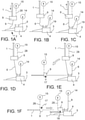
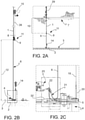
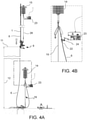
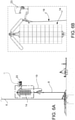
- the retaining cable 19 is considerably shorter than the damping cable 6 and retains the damping buoy 14 in a ready position at a distance vertically over the fixed receiving structure 4 ( figures 1A , 2B , 3A ).
- the method comprises a step of positioning and fixing of an auxiliary cable 21 onto the fixed receiving structure 4 (to be used as messenger), in which the auxiliary cable 21 extends through the redirecting device 5 and forms two opposite ends extending outside the redirecting device 5.
- a first end of the auxiliary cable 21 (possibly in the form of a loop, ring or hook) is connectable, e.g. by means of a hook, to a free end 22 (possibly in the form of a loop, ring or hook) of the damping cable 6 opposite to its end connected with the pipeline end termination device 9.
- a second end of the auxiliary cable 21 (possibly in the form of a loop, ring or hook) is configured to be gripped by a gripping member 24 of a remotely operated vehicle (ROV) 23 and pulled to pull the free end 22 of the damping cable 6 through the redirecting device 5 ( figures 2C , 3B, 3C ).
- ROV remotely operated vehicle
- the step of paying-out of the first length 10 of the pipeline 1 from the laying vessel 7 comprises lowering the pipeline end termination device 9 until reaching the provisional anchoring position 11 at a determined vertical safety distance 12, preferably 80-110 m and more preferably 95-100m, from the seabed 3 ( figure 2B ).
- the assembly and the laying of the pipeline 1 preferably takes place by "J” laying by means of a “J” laying tower 29 installed on the laying vessel 7 ( figure 2A ).
- the suspension buoy 15 can be connected to the pipeline end termination device 9 either before or after the arrival of the pipeline 1 in the provisional anchoring position 11, preferably by means of a (steel) suspension cable 28 having two ends (provided with a hook, ring or eyelet) removably connectable one to a hooking ring of the pipeline end termination device 9 and the other to a hooking ring of the suspension buoy 15.
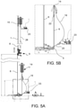
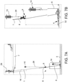
- the suspension cable 28 is shorter than the first length 10 of the pipeline 1 and retains the suspension buoy 15 in a position at a distance vertically above the pipeline end termination device 9 ( figures 1D , 7A).
- the suspension cable 28 can be connected to the pipeline end termination device 9 underwater by the remotely operated vehicle (ROV) 23 or aboard the laying vessel 7.
- ROV remotely operated vehicle
- the step of extending the damping cable 6 by the pipeline end termination device 9 through the redirecting device 5 until the damping buoy 14 comprises the steps of:
- the damping cable 6 itself can be pre-installed on the fixed receiving structure 4 and extended through the redirecting device 5 before the extension of the pipeline 1 in the provisional anchoring position 11 or before installing the fixed receiving structure 4 on the seabed 3.
- the subsequent step of inclination of the initial end length 8 from the vertical orientation towards a horizontal or nearly horizontal orientation to the lowered position 17 is performed by assembling and paying-out a further length 16 of the pipeline 1 from the laying vessel 7 and, either at the same time or in alternating steps, by moving the laying vessel 7 away from the target position 2 in a predetermined direction of initial extension of the pipeline and, possibly, by adjusting an inclination angle (inclination angle of the "J" laying tower 29) between the pipeline 1 released from the vessel 7 and the vessel 7.
- Predetermined coordination tables calculated as a function of sea depth and of the length and catenary configuration of the pipeline 1, can be used to coordinate the timing and the assembly and releasing speed of the pipeline 1 with the timing and movement speed of the laying vessel 7 and with the timing and width of the inclination angle between the pipeline 1 released from the vessel 7 and the vessel 7,
- the pipeline end termination device 9 may have, for example, an inclination of about 20° with respect to the horizontal and a distance of about 20m from the fixed receiving structure 4.
- the load values on the devices of the laying tower of the vessel 7 and/or the movements and/or the position of the damping cable 6 are monitored, preferably by optical detection means (e.g. one or more cameras 31) aboard a ROV 23 or aboard the fixed receiving structure 4, adjusting the position and/or the speed of the laying vessel 7 and/or the feeding speed of the pipeline 1, also according to the movements and/or the position of the damping cable 6.
- optical detection means e.g. one or more cameras 31
- This monitoring can be performed by optical detection means (e.g. one or more cameras 31) aboard a ROV 23 or aboard the fixed receiving structure 4.
- optical detection means e.g. one or more cameras 31
- the position can be corrected by adjusting the position of the laying vessel 7.
- the pipeline end termination device 9 as well as the initial end length portion 8 of the pipeline 1 are still spaced from the seabed 3, or in other words, are not abutting on the seabed 3, also by virtue of the suspension force of the suspension buoy 15.
- the successive step of abutting and anchoring of the pipeline end termination device 9 in the final abutting position 18 may comprise an abutment and anchoring of the pipeline end termination device 9 at a distance from the fixed receiving structure 4, e.g. directly on the seabed 3 or on a pre-installed anchoring foundation.
- the damping buoy 14 and of the suspension buoy 15 can be uncoupled from the pipeline end termination device 9, e.g. by means of the ROV 23.
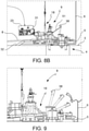
- the step of abutting the pipeline end termination device 9 in the final abutting position 18 comprises moving the laying vessel 7 and/or adjusting the inclination angle between the pipeline 1 released from the vessel 7 and the vessel 7 so as to approach the pipeline end termination device 9 towards the fixed receiving structure 4 up to abutting the pipeline end termination device 9 in the final abutting position 18 directly on the fixed receiving structure 4 ( figures 8A , 8B) and then stopping the pipeline end termination device 9 in the final abutting position 18, by positioning one or more stopping elements engaging with the pipeline end termination device 9 and the fixed receiving structure 4 ( figure 9 ) .
- a successive, further feeding of the pipeline 1 together with a movement of the laying vessel 7 further lowers the initial end length 8 until it abuts on the seabed 3.
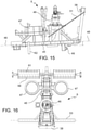
- the redirecting device 5 comprises one or more redirecting pulleys 25 or redirecting guides forming one or more supporting and redirecting surfaces 26 facing downwards, as well as one or more side guides 27 to prevent lateral exiting of the cable redirected by the redirecting surfaces 26 and/or to facilitate the insertion of the damping cable 6 into the groove of the redirecting pulley 25 during its tensioning ( figures 3C , 14 , 18 ).
- a channel may be further provided between two rollerboxes of the redirecting device 5 for supporting the auxiliary cable 21.
- the fixed receiving structure 4 forms a landing ramp 32, with one or more guiding surfaces 33 forming a guide and an abutment from the bottom to the pipeline end termination device 9.
- the guiding surfaces 33 extend on two opposite sides with respect to the redirecting device 5 and in the same direction (preferably parallel to the target orientation provided for the pipeline end termination device 9), in such a way that the damping cable 6 redirected by the redirecting device 5 can feed the pipeline end termination device 9 along the guiding surfaces 33.
- the landing ramp 32 comprises two steel beams transversally spaced apart and extending both approximately in the target orientation direction provided for the pipeline end termination device 9, wherein the guiding surfaces 33 are formed by upper flanges of the beams 34.
- the fixed receiving structure 4 further forms one or more stop portions 35 which form a travel stop abutment against a further horizontal movement of the pipeline end termination device 9 along the guiding surfaces 33.
- the stop portions 35 may comprise two steel cylinders extending in vertical direction, and the stop portions 35 are arranged at ends of the guiding surfaces 33 (or of the beams 34) on two opposite sides with respect to the redirecting device 5.
- the stop portions 35 can form or be formed by portions of vent hatch for a suction piles foundation 36 on which the fixed receiving structure 4 is installed.
- the fixed receiving structure 4 further comprises a locking pole 37 which can be engaged by shape connection by a corresponding locking yoke 38 of the pipeline end termination device 9.
- the anchoring is permanent because it is required and sized for the maximum residual pull on the pipeline end termination device 9 under the maximum environmental loads in service.
- the locking pole 37 is preferably positioned at, e.g. over, the redirecting device 5, and protrudes upwards so that the locking yoke 38 can engage the locking pole 37 by means of a movement from the top downwards.
- the locking pole 37 forms a barb 52 to prevent an accidental lifting and undesired disengagement of the locking yoke 38, when the latter is pulled and positioned in abutment against a side surface of the locking pole 37 ( figures 11 , 18) .
- This is a precautionary measure during the step of installing with the laying vessel 7 subject to wave motion and in which the pipeline end termination device 9 is still lightened from the suspension buoy 15.
- the fixed receiving structure 4 can also comprise a plurality of seats 41 to receive and keep ready locking pins 42 for a side locking of the pipeline end termination device 9 with respect to the fixed receiving structure 4.
- the locking pins may be necessary to withstand operating and service loads applied to the connector 46 of the pipeline end termination device 9.
- the fixed receiving structure 4 may also comprise one or more, preferably two, ballast seats 39, formed for example on two opposite sides of the redirecting device 5 and, preferably, also on two opposite sides and externally with respect to the landing ramp 32, in order to receive ballast masses and keep them ready. It may be necessary to install such ballast masses on ballast seats 47 arranged on the device driven end 9 to weigh down and increase the stability of the pipeline end termination device 9 to withstand operating and service loads applied to the connector 46 of the pipeline end termination device 9.
- the fixed receiving structure 4 can also comprise one or more ROV docking platforms 40 for a removable coupling and parking of the remotely operated vehicle 23.
- the ROV docking platform 40 is preferably positioned laterally on the outside and spaced from the landing ramp 32, in such a way as to avoid encroachments of space between a parked ROV 23 and the pipeline end termination device 9 coupled to the fixed receiving structure 4.
- the fixed receiving structure 4 comprises one or more hooking seats 43 for transporting and lifting the fixed receiving structure 4 before it is installed on the seabed 3.
- the individual components of the fixed receiving structure 4 are mounted on a plate 44 which forms an upper plate of the foundation to the suction piles foundation 36.
- the pipeline end termination device 9 comprises a supporting structure 45 having a rear side 54 connectable to the free end of the pipeline 1, a front side 55 opposite to the rear side 54, a bottom side 56 intended to be facing downwards, an upper side 57 opposite the lower side 56 and a longitudinal extension from the rear side 54 to the front side 55 along a longitudinal axis 48 aligned with the orientation of the end of the pipeline 1.
- the supporting structure 45 supports a connector 46 for the fluidic connection to the end of the pipeline 1 to an application, for example with a pipeline of a well head.
- the pipeline end termination device 9 comprises one or two front sliding bars 53, connected to the supporting structure 45 near the rear side 55 for slidingly abutting from above on a landing ramp 32.
- the front sliding bars 53 may comprise cylindrical tubular profiles extending in a transversal (horizontal) direction with respect to the longitudinal axis 48.
- the pipeline end termination device 9 further comprises one or two rear resting profiles 58 connected to the supporting structure 45 near the rear side 54 for slidingly abutting on the landing ramp 32 from above.
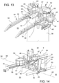
- the rear supporting profiles 58 may comprise plates extending in a transversal (horizontal) direction with respect to the longitudinal axis 48 and, possibly, parallel to the front sliding bars 53 ( Figure 14 ).
- the front sliding bars 53 may comprise a mark 59 (e.g. a colored area) intended to be positioned at the guiding surfaces 33 (of the beams 34) and/or at a corresponding mark 60 (e.g. a colored area) of the stop portions 35 of the fixed receiving structure 4.
- a mark 59 e.g. a colored area
- a corresponding mark 60 e.g. a colored area
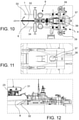
- the rear supporting profiles 58 form a hole array 61 for receiving locking pins 42 in selectable positions to provide a side engagement or locking against the landing ramp 32 in order to lock the pipeline end termination device 9 against unwanted and/or excessive lateral displacements ( figures 12 , 18), e.g. caused in service of the field by operating loads applied on the connector 46 of the pipeline end termination device 9.
- the locking pins 42 may be positioned by the ROV 23.
- the pipeline end termination device 9 can further comprise one or two rough guiding portions 62 protruding from the supporting structure 45 downwards in a region which is intended to be placed at a free space 63 of the landing ramp 32, e.g. in the free space between the two beams 34.
- the rough guiding portions 62 may be formed by vertical bars or tubular sections and facilitate the initial insertion of the pipeline end termination device 9 on the landing ramp 32 in addition to preventing (by engaging from the inside against the beams 34) rough side misplacements of the pipeline end termination device 9.
- the pipeline end termination device 9 further comprises the aforesaid locking yoke 38 arranged on the front side of the supporting structure 45 and connected to the supporting structure 45 in a rotatable manner about a (horizontal) tilting axis 50 transversal to the longitudinal axis 48.
- the locking yoke 38 is rotatable or tiltable between a raised engagement position ( figures 8B , 14 , 15 , 17 ) and a lowered position of engagement with the locking pole 37 ( figures 9 , 11 , 18 ).
- the locking yoke 38 is permanently biased towards the lowered engaging position, and releasable retaining means are provided to hold it in the raised disengaging position.
- the locking yoke 38 in the raised disengagement position extends with a forward inclination with respect to the tilting axis 50. In this way, the resultant of the gravitation force of the locking yoke 38 is orthogonally spaced from the tilt axis 50 and the locking yoke 38 is biased by its own weight towards the lowered position of engagement.
- elastic means and/or auxiliary traction means drive may be provided to bias the locking yoke 38 towards the lowered position of engagement.
- the releasable retainer means may comprise a retaining sling 51 which binds the locking yoke 38 to the supporting structure 45 and which can be released, e.g. cut by a cutting tool of an underwater remotely operated vehicle (ROV) 23 ( figures 14 , 15).
- ROV underwater remotely operated vehicle
- the locking yoke 38 has the shape of a simple frame with two uprights and a crosspiece and can form two opposite guiding-in surfaces 65 converging to facilitate the engagement and the correct mutual positioning with the locking pole 37 ( figure 11 ).
- the pipeline end termination device 9 may comprise one or more, preferably two additional ballast seats 47 connected to the supporting structure 48 and positioned, for example, on its two opposite sides with respect to the longitudinal axis 48 and, preferably, also on two opposite sides and externally with respect to the locking yoke 38.
- the pipeline end termination device 9 also comprises a connecting eyelet 49 for connecting an end of the damping cable 6.
- the connecting eyelet 49 is preferably positioned on the front side of the supporting structure 45 in a central position with respect to the longitudinal axis 48, so that the traction of the damping cable 6 aligns the longitudinal axis 48 of the pipeline end termination device 9 with the orientation of the damping cable 6.
- the pipeline end termination device 9 can also comprise a docking bar 64 for docking an underwater remotely operated vehicle (ROV) 23 in such a position as to allow a visual monitoring, by means of the camera aboard the ROV 23, of the steps of approaching, supporting and/or locking of the pipeline end termination device 9 on the fixed receiving structure 4.
- ROV underwater remotely operated vehicle
- the damping cable 6 feeds the pipeline end termination device 9 towards the final abutting position ( figure 8A ), the front sliding bars 53 abut on the landing ramp 32 and slide along the landing ramp 32 until they abut against the stop portions 35.
- the correct positioning can be checked (e.g. by means of a video camera installed on a ROV 23 docked to the pipeline end termination device 9) and adjusted by virtue of the marks 59 on the front sliding bars 53 and the corresponding marks 60 on the stop portions 35, the positions of which must correspond ( figures 8B , 17).
- the locking yoke 38 is overturned into the engaging position with the locking pole 37, by releasing the retaining means, e.g. by shearing the retaining sling 51 by means of a ROV 23 ( figures 9 , 18).
- the locking yoke 38 is fed into contact against the locking pole 37 ( figures 10 and 11 ). This is preferably achieved by moving away the laying vessel 7 and applying a traction force on the end of the pipeline 1 which is greater than the force of the damping buoy, or alternatively by separating the connection between the damping buoy 14 and the pipeline end termination device 9.
- the locking of the orientation on the horizontal plane of the pipeline end termination device 9 with respect to the fixed receiving structure 4 can be achieved by taking the locking pins 42 from their seats 41 and inserting them in the selected holes of the holes 61 of the rear supporting profiles 58 so as to engage the lateral beams 34 of the landing ramp 32 and/or restrict future movements.
- the ROV 23 may also be used for this operation ( figures 12 , 18).
- the components described above are preferably made of steel or, alternatively of synthetic or composite material, possibly reinforced with fibers.
- the damping buoy 14 and suspension buoy 15 are underwater floats of construction known in itself (e.g. with syntactic foam modules, pressure chambers or ballastable, etc.).
Landscapes
- Engineering & Computer Science (AREA)
- General Engineering & Computer Science (AREA)
- Mechanical Engineering (AREA)
- Chemical & Material Sciences (AREA)
- Combustion & Propulsion (AREA)
- Ocean & Marine Engineering (AREA)
- Laying Of Electric Cables Or Lines Outside (AREA)
Claims (15)
- Verfahren zum Verlegen eines Offshore-Rohres (1), umfassend:- Installieren in einer Zielposition (2) auf dem Meeresgrund (3) einer fixierten Aufnahmestruktur (4), welche eine Umlenkvorrichtung (5) für ein Dämpfungskabel (6) aufweist,- auf einem Verlegeschiff (7), Breitstellen des Rohres (1) mit einer initialen Endlänge (8), an welcher eine Rohrleitung-Endanschlussvorrichtung (9) montiert wird,- Verbinden einer Unterwasser-Aufhängung-Boje (15) mit der Rohrleitung-Endanschlussvorrichtung (9), wobei die Unterwasser-Aufhängung-Boje (15) eine Aufhängungskraft, welche vertikal nach oben gerichtet ist, auf die Rohrleitung-Endanschlussvorrichtung (9) aufbringt,- Ausgeben einer ersten Länge (10) des Rohres (1) mit der Rohrleitung-Endanschlussvorrichtung (9) von dem Verlegeschiff (7) vertikal in Richtung des Meeresgrundes (3) zu einer provisorischen Verankerungsposition (11), in welcher die initiale Endlänge (8) eine näherungsweise vertikale Orientierung mit einem vertikalen Sicherheitsabstand (12) zwischen der Rohrleitung-Endanschlussvorrichtung (9) und dem Meeresgrund (3) aufweist,- Verlängern eines Dämpfungskabels (6) von der Rohrleitung-Endanschlussvorrichtung (9) durch die Umlenkvorrichtung (5) zu einer Unterwasser-Dämpfung-Boje (14), so dass das Dämpfungskabel (6), gleitbar gehaltert und umgelenkt durch die Umlenkvorrichtung (5) und gespannt durch eine Auftriebskraft der Dämpfung-Boje (14), eine provisorische Dämpfungsverankerung der Rohrleitung-Endanschlussvorrichtung (9) zu der fixierten Aufnahmestruktur (4) bildet,gekennzeichnet durch:- Bewegen des Verlegeschiffs (7) horizontal weg von der fixierten Aufnahmestruktur (4) und Ausgeben, von dem Verlegeschiff (7), einer weiteren Länge (16) des Rohres (1), um die initiale Endlänge (8) progressiv von der vertikalen Orientierung in Richtung einer horizontalen Orientierung bis zu einer abgesenkten Position (17) zu neigen,- mit der initialen Endlänge (8) in der abgesenkten Position (17), Bewegen des Verlegeschiffs (7) zu einem Positionieren der initialen Endlänge (8) in horizontaler Richtung in einer finalen Anlageposition (18) in Bezug auf die Zielposition (2), dann Anlegen der Rohrleitung-Endanschlussvorrichtung (9) in der finalen Anlageposition (18),- während der Schritte eines Neigens zu der abgesenkten Position (17) und eines horizontalen Positionierens der initialen Endlänge (8):- Verwenden der Aufhängungskraft der Aufhängung-Boje (15), um wenigstens einen Teil des Gewichtes der Rohrleitung-Endanschlussvorrichtung (9) auszugleichen,- Verwenden der Auftriebskraft der Dämpfung-Boje (14), um eine Zugkraft der initialen Endlänge (8) des Rohres (1) auszugleichen und die Bewegungen der initialen Endlänge (8) des Rohres (1) zu dämpfen,- Verwenden der gleitbaren Halterung des umgelenkten Dämpfungskabels (6), um relative Kompensationsbewegungen zwischen der Rohrleitung-Endanschlussvorrichtung (9) und der fixierten Aufnahmestruktur (4) zu erlauben.
- Verfahren nach Anspruch 1, umfassend einen Schritt eines temporären Fixierens der Dämpfung-Boje (14) an der fixierten Aufnahmestruktur (4), vor dem Schritt des Verlängerns des Rohres (1) in Richtung der temporären Verankerungsposition (11), mittels eines Rückhaltekabels (19), welches kürzer ist als das Dämpfungskabel (6) und die Dämpfung-Boje (14) in einer Bereitschaftsposition bei einem Abstand vertikal oberhalb der fixierten Aufnahmestruktur (4) zurückhält,und ferner umfassend entweder die folgenden Schritte:A) vor dem Schritt eines Ausgebens des Rohres (1) in Richtung der provisorischen Verankerungsposition (11):- Positionieren und Fixieren eines Hilfskabels (21) an der fixierten Aufnahmestruktur (4), wobei sich das Hilfskabel (21) durch die Umlenkvorrichtung (5) erstreckt und zwei entgegengesetzte Enden bildet, welche sich außerhalb der Umlenkvorrichtung (5) erstrecken, B) nach dem Schritt eines Ausgebens des Rohres (1) zu der provisorischen Verankerungsposition (11):- Verbinden eines ersten Endes des Hilfskabels (21) mit einem freien Ende (22) des Dämpfungskabels (6), welches sich von der Rohrleitung-Endanschlussvorrichtung (9) erstreckt,- Greifen eines zweiten Endes des Hilfskabels (21) und Ziehen daran, um das freie Ende (22) des Dämpfungskabels (6) durch die Umlenkvorrichtung (5) zu ziehen,- Greifen des freien Endes (22) des Dämpfungskabels (6) und Verbinden des freien Endes (22) mit der Dämpfung-Boje (14), welche durch das Rückhaltekabel (19) in der Bereitschaftsposition gehalten wird,oder die folgenden Schritte:- vor dem Schritt eines Ausgebens des Rohres (1) in Richtung der provisorischen Verankerungsposition (11), Vorinstallieren des Dämpfungskabels (6) an der fixierten Aufnahmestruktur (4), wobei sich das Dämpfungskabel (6) durch die Umlenkvorrichtung (5) erstreckt,- nach dem Schritt eines Ausgebens des Rohres (1) zu der provisorischen Verankerungsposition (11),
Greifen eines Endes des Dämpfungskabels (6) und Verbinden des Endes mit der Rohrleitung-Endanschlussvorrichtung (9), und Greifen eines weiteren Endes des Dämpfungskabels (6) und Verbinden des weiteren Endes mit der Dämpfung-Boje (14), welche durch das Rückhaltekabel (19) in der Bereitschaftsposition gehalten wird,und umfassend die folgenden Schritte:- Lösen des Rückhaltekabels (19) und Spannen des Dämpfungskabels (6) durch Anheben des Rohres (1) über eine Länge zurück in das Verlegeschiff (7) oder durch Bewegen des Verlegeschiffs (7) weg von der Zielposition (2),- bei gelöstem Rückhaltekabel (19), Entfernen des Rückhaltekabels (19) von der fixierten Aufnahmestruktur (4) oder von der Dämpfung-Boje (14). - Verfahren nach einem der vorhergehenden Ansprüche, umfassend, während des Schrittes eines Neigens der initialen Endlänge (8) von der vertikalen Orientierung zu der abgesenkten Position (17),- einen Schritt eines Variierens eines Neigungswinkels zwischen dem Rohr (1), welches aus dem Verlegeschiff (7) austritt, und dem Verlegeschiff (7), und/oder- die folgenden Schritte:- Überwachen der Position des Dämpfungskabels (6) über optische Detektionsmittel (31), und- Anpassen der Position des Verlegeschiffs (7) und der Ausgabegeschwindigkeit des Rohres (1) ebenfalls in Abhängigkeit der Position des Dämpfungskabels (6).
- Verfahren nach einem der vorhergehenden Ansprüche, umfassend die folgenden Schritte:- wenn sich die initiale Endlänge (8) des Rohres (1) in der abgesenkten Position (17) befindet, Überwachen der Position des Dämpfungskabels (6) in Bezug auf eine Zielorientierungsmarkierung (30), welche an der fixierten Aufnahmestruktur (4) gebildet ist, über optische Detektionsmittel (31), und- in einem Fall einer Fehlpositionierung des Dämpfungskabels (6) in Bezug auf die Zielorientierungsmarkierung (30), Korrigieren der Position durch Anpassen der Position des Verlegeschiffs (7).
- Verfahren nach einem der vorhergehenden Ansprüche, wobei der Schritt eines Anlegens und Verankerns der Rohrleitung-Endanschlussvorrichtung (9) in der finalen Anlageposition (18) umfasst:- mittels des Verlegeschiffs (7), Annähern der Rohrleitung-Endanschlussvorrichtung (9) in Richtung der fixierten Aufnahmestruktur (4) bis die Rohrleitung-Endanschlussvorrichtung (9) in der finalen Anlageposition (18) direkt an der fixierten Aufnahmestruktur (4) anliegt,- anschließend Verriegeln der Rohrleitung-Endanschlussvorrichtung (9) in der finalen Anlageposition (18) durch Positionieren eines mehrerer Verriegelungselemente (38, 42, 52) in Eingriff mit der Rohrleitung-Endanschlussvorrichtung (9) und mit der fixierten Aufnahmestruktur (4),- anschließend Bewegen des Verlegeschiffs (7) und weiter Absenken der initialen Endlänge (8) bis sie auf dem Meeresgrund (3) anliegt, und/oder wobei, während des Schritts eines Anlegens der Rohrleitung-Endanschlussvorrichtung (9):- Anlegen und Gleiten vorderer Gleitstäbe (53) der Rohrleitung-Endanschlussvorrichtung (9) an einer Anlagerampe (32) der fixierten Aufnahmestruktur (4) bis die vorderen Gleitstäbe (53) gegen Anschlagabschnitte (35) der fixierten Aufnahmestruktur (4) anschlagen,- Prüfen der korrekten Positionierung der Rohrleitung-Endanschlussvorrichtung (9) unter Verwendung von Markierungen (59), welche an den vorderen Gleitstäben (53) aufgebracht sind, und entsprechender Markierungen (60), welche an den Anschlagabschnitten (35) aufgebracht sind.
- Verfahren nach einem der vorhergehenden Ansprüche, wobei der Schritt eines Verankerns der Rohrleitung-Endanschlussvorrichtung (9) in der finalen Anlageposition (18) umfasst:- Umlegen eines Verriegelungsbügels (38) der Rohrleitung-Endanschlussvorrichtung (9) von einer angehobenen außer Eingriff gebrachten Position zu einer abgesenkten Position eines Eingriffs mit einem Anschlagloch (37) der fixierten Aufnahmestruktur (4),- anschließend Trennen der Verbindung zwischen der Dämpfung-Boje (14) und der Rohrleitung-Endanschlussvorrichtung (9),wobei das Verfahren ferner die folgenden Schritte umfasst:- Verriegeln der Orientierung an einer horizontalen Ebene der Rohrleitung-Endanschlussvorrichtung (9) in Bezug auf die fixierte Aufnahmestruktur (4) durch Einsetzen von Verriegelungsstiften (42) in ausgewählte Löcher einer Lochanordnung (61) der Rohrleitung-Endanschlussvorrichtung (9), um mit der Anlagerampe (32) lateral einzugreifen.
- System zum Verlegen eines Offshore-Rohres (1), welches dazu eingerichtet ist, ein Verfahren zu implementieren, wobei:- das Rohr (1) an einem Verlegeschiff (7) bereitgestellt ist und eine erste Länge (10) des Rohres (1) von dem Verlegeschiff (7) vertikal in Richtung des Meeresgrundes (3) ausgegeben wird, bis es eine provisorische Verankerungsposition (11) erreicht, wobei eine initiale Endlänge (8) des Rohres (1) eine näherungsweise vertikale Orientierung und einen vertikalen Sicherheitsabstand (12) zwischen der Rohrleitung-Endanschlussvorrichtung (8) und dem Meeresgrund (3) aufweist,- sich dann das Verlegeschiff (7) horizontal bewegt und eine weitere Länge (16) des Rohres (1) ausgibt, um eine graduelle Neigung der initialen Endlänge (8) von der vertikalen Orientierung in Richtung einer horizontalen Orientierung zu erlauben, bis sie eine abgesenkte Position (17) erreicht,- mit der initialen Endlänge (8) in der abgesenkten Position (17), sich das Verlegeschiff (7) bewegt, um die initiale Endlänge (8) in horizontaler Richtung in einer finalen Anlageposition (18) in Bezug auf eine Zielposition (2) zu platzieren, wobei anschließend die initiale Endlänge (8) in der finalen Anlageposition (18) angelegt ist,wobei das Verlegesystem umfasst:- eine fixierte Aufnahmestruktur (4), welche in der Zielposition (2) auf dem Meeresgrund (3) installiert sein kann, wobei die fixierte Aufnahmestruktur (4) eine Umlenkvorrichtung (5) für ein Dämpfungskabel (6) aufweist,- eine Rohrleitung-Endanschlussvorrichtung (9), welche an der initialen Endlänge (8) des Rohres (1) montiert sein kann,- eine Unterwasser-Aufhängung-Boje (15), welche lösbar mit der Rohrleitung-Endanschlussvorrichtung (9) verbindbar ist, um eine vertikal nach oben gerichtete Aufhängungskraft auf die Rohrleitung-Endanschlussvorrichtung (9) aufzubringen,- eine Unterwasser-Dämpfung-Boje (14), welche eine Auftriebskraft aufweist,- ein Dämpfungskabel (6), welches lösbar mit der Dämpfung-Boje (14) und der Rohrleitung-Endanschlussvorrichtung (9) verbindbar ist und sich durch die Umlenkvorrichtung (5) erstreckt, so dass das Dämpfungskabel (6) gleitbar gehaltert und umgelenkt durch die Umlenkvorrichtung (5) ist und durch die Auftriebskraft der Dämpfung-Boje (14) gespannt ist, um eine provisorische Dämpfungsverankerung der Rohrleitung-Endanschlussvorrichtung (9) an der fixierten Aufnahmestruktur (4) zu bilden, wobei während des Schritts eines Neigens zu der abgesenkten Position und während des Schritts eines Positionierens der initialen Endlänge (8) des Rohres (1) in einer horizontalen Richtung:- die Aufhängungskraft der Aufhängung-Boje (15) wenigstens einen Teil des Gewichtes der Rohrleitung-Endanschlussvorrichtung (9) ausgleicht,- die Auftriebskraft der Dämpfung-Boje (14) eine Zugkraft der initialen Endlänge (8) des Rohres (1) ausgleicht,- die gleitbare Halterung des umgelenkten Dämpfungskabels (6) relative Kompensationsbewegungen zwischen der Rohrleitung-Endanschlussvorrichtung (9) und der fixierten Aufnahmestruktur (4) erlaubt, dadurch gekennzeichnet, dass:- die fixierte Aufnahmestruktur (4) eine Anlagerampe (32) mit einer oder mehreren Führungsflächen (33) bildet, welche eine Führung und eine Anlagehalterung von unten für die Rohrleitung-Endanschlussvorrichtung (9) bilden, wobei sich die Führungsflächen (33) an zwei in Bezug auf die Umlenkvorrichtung (5) entgegengesetzten Seiten und in der gleichen Richtung erstrecken, so dass das Dämpfungskabel (6) die Rohrleitung-Endanschlussvorrichtung (9) entlang der Führungsflächen (33) zieht.
- System nach Anspruch 7, wobei:- die Umlenkvorrichtung (5) eine oder mehrere Umlenkrollen (25) oder Umlenkführungen, welche eine oder mehrere nach unten gerichtete Halterung-und-Umlenk-Flächen (26) bilden, sowie eine oder mehrere seitliche Führungen (27) umfasst, um ein laterales Austreten des durch die Umlenkflächen (26) umgelenkten Kabels zu verhindern.
- System nach Anspruch 7 oder 8, wobei:- die Anlagerampe (33) zwei Stahlträger umfasst, welche transversal beabstandet sind und sich beide näherungsweise in einer Zielorientierungsrichtung erstrecken, welche für die Rohrleitung-Endanschlussvorrichtung (9) bereitgestellt ist, wobei die Führungsflächen (33) durch obere Flansche der Träger (34) gebildet sind,- die fixierte Aufnahmestruktur (4) ferner einen oder mehrere Anschlagabschnitte (35) bildet, welche eine Bewegungsanschlaganlage gegen eine weitere horizontale Bewegung der Rohrleitung-Endanschlussvorrichtung (9) entlang der Führungsflächen (33) bilden.
- System nach Anspruch 9, wobei die Anschlagabschnitte (35) zwei Stahlzylinder umfassen, welche sich in vertikaler Richtung erstrecken und an Enden der Führungsflächen (33) an zwei in Bezug auf die Umlenkvorrichtung (5) entgegengesetzten Seiten angeordnet sind.
- System nach einem der Ansprüche 7 bis 10, wobei die fixierte Aufnahmestruktur (4) eine Verriegelungsstange (37) umfasst, welche von oben durch einen entsprechenden Verriegelungsbügel (38) der Rohrleitung-Endanschlussvorrichtung (9) in Eingriff genommen werden kann, und wobei, optional:- die Verriegelungsstange (37) einen Widerhaken (52) bildet, um den Verriegelungsbügel (38) an einem unerwünschten Entkoppeln zu hindern,- die fixierte Aufnahmestruktur (4) Ballast-Sitze (39) umfasst, welche an zwei entgegengesetzten Seiten der Umlenkvorrichtung (5) und außerhalb der Anlagerampe (32) für ein zusätzliches temporäres beladen der fixierten Aufnahmestruktur (4) mit Ballast gebildet sind.
- System nach einem der Ansprüche von 7 bis 11, wobei die Rohrleitung-Endanschlussvorrichtung (9) umfasst:- eine Halterungsstruktur (45), welche eine hintere Seite (54), welche mit dem freien Ende des Rohres (1) verbunden sein kann, eine Vorderseite (55), welche der hinteren Seite (54) entgegengesetzt ist, und eine longitudinale Achse (48) aufweist, welche mit der Orientierung des Endes des Rohres (1) ausgerichtet ist,- einen Connector (46) zum fluidischen Verbinden des Rohrendes (1) mit einer Anwendungseinrichtung,- einen vorderen Gleitstab (53), welcher mit der Halterungsstruktur (45) in der Nähe der vorderen Seite (55) verbunden ist, um von oben an einer Anlagerampe (32) der fixierten Aufnahmestruktur (4) gleitend anzuliegen,- ein hinteres Anlageprofil (58), welches mit der Halterungsstruktur (45) in der Nähe der hinteren Seite (54) verbunden ist, um von oben an einer Anlagerampe (32) anzuliegen,wobei der vordere Gleitstab (53) eine Markierung (59) umfasst, welche dazu bestimmt ist, an einer entsprechenden Markierung (60) eines Anschlagabschnitts (35) der fixierten Aufnahmestruktur (4) positioniert zu sein,wobei das hintere Anlageprofil (58) eine Lochanordnung (61) bildet, um Verriegelungsstifte (42) in ausgewählten Positionen aufzunehmen, um einen seitlichen Eingriff gegen die Anlagerampe (32) bereitzustellen,wobei die Rohrleitung-Endanschlussvorrichtung (9) einen oder mehrere raue Führungsabschnitte (62) umfasst, welche von der Halterungsstruktur (45) nach unten in einem Bereich vorstehen, welcher dazu bestimmt ist, an einem freien Raum (63) der Anlagerampe (32) positioniert zu sein.
- System nach Anspruch 11, wobei der Verriegelungsbügel (38) an der vorderen Seite der Halterungsstruktur (45) angeordnet ist und mit der Halterungsstruktur (45) verbunden ist, so dass dieser zwischen einer angehobenen außer Eingriff gebrachten Position und einer abgesenkten Position eines Eingriffs mit der Verriegelungsstange (37) umgelegt werden kann,wobei der Verriegelungsbügel (38) permanent in Richtung der abgesenkten in Eingriff gebrachten Position vorbelastet ist,und lösbare Rückhaltemittel bereitgestellt sind, um den Verriegelungsbügel (38) in der angehobenen außer Eingriff gebrachten Position zu halten, wobei der Verriegelungsbügel (38) durch sein eigenes Gewicht in Richtung der abgesenkten in Eingriff gebrachten Position vorbelastet ist und die lösbaren Rückhaltemittel eine Rückhalteschlinge (51) umfassen, welche den Verriegelungsbügel (38) an die Halterungsstruktur (45) bindet und abgetrennt werden kann, um diesen freizugeben.
- System nach Anspruch 13, wobei der Verriegelungsbügel (38) zwei entgegengesetzte und konvergierende Einführungsflächen (65) bildet, um den Eingriff und die korrekte gegenseitige Positionierung mit der Anschlagstange (37) zu erleichtern.
- System nach einem der Ansprüche 7 bis 14, wobei die Rohrleitung-Endanschlussvorrichtung (9) weitere Ballastsitze (47) umfasst.
Applications Claiming Priority (2)
| Application Number | Priority Date | Filing Date | Title |
|---|---|---|---|
| IT102017000057253A IT201700057253A1 (it) | 2017-05-26 | 2017-05-26 | "Metodo e sistema per la posa di una pipeline sottomarina” |
| PCT/IB2018/053734 WO2018215981A2 (en) | 2017-05-26 | 2018-05-25 | Method and system for laying a submarine pipeline |
Publications (2)
| Publication Number | Publication Date |
|---|---|
| EP3631266A2 EP3631266A2 (de) | 2020-04-08 |
| EP3631266B1 true EP3631266B1 (de) | 2022-03-16 |
Family
ID=59930715
Family Applications (1)
| Application Number | Title | Priority Date | Filing Date |
|---|---|---|---|
| EP18792461.8A Active EP3631266B1 (de) | 2017-05-26 | 2018-05-25 | Verfahren und system zum verlegen einer unterwasserrohrleitung |
Country Status (5)
| Country | Link |
|---|---|
| US (1) | US11549614B2 (de) |
| EP (1) | EP3631266B1 (de) |
| AU (1) | AU2018273178B2 (de) |
| IT (1) | IT201700057253A1 (de) |
| WO (1) | WO2018215981A2 (de) |
Cited By (1)
| Publication number | Priority date | Publication date | Assignee | Title |
|---|---|---|---|---|
| WO2024013564A1 (en) * | 2022-07-13 | 2024-01-18 | Acergy France SAS | Initiation of subsea installation operations |
Families Citing this family (4)
| Publication number | Priority date | Publication date | Assignee | Title |
|---|---|---|---|---|
| GB2580351B (en) * | 2019-01-03 | 2021-12-22 | Subsea 7 Us Llc | Subsea connection of pipeline sections |
| CN112962697B (zh) * | 2021-02-09 | 2022-07-15 | 浙江省海洋开发研究院 | 海底电缆埋设开槽方法 |
| US11668412B1 (en) * | 2022-01-05 | 2023-06-06 | Fmc Technologies, Inc. | Yoke over pipeline end termination assembly and method of use |
| CN118912270B (zh) * | 2024-09-30 | 2025-01-28 | 中交第一航务工程局有限公司 | 内河沉管跨河道运输系统及短距离运输方法 |
Family Cites Families (5)
| Publication number | Priority date | Publication date | Assignee | Title |
|---|---|---|---|---|
| US3690112A (en) * | 1971-02-10 | 1972-09-12 | Exxon Production Research Co | Method and apparatus for attaching pipelines to offshore structures |
| US4133182A (en) * | 1977-01-13 | 1979-01-09 | Societe Nationale Elf Aquitaine (Production) | Apparatus and method of connecting a flowline to a subsea station |
| US7654773B2 (en) * | 2007-12-20 | 2010-02-02 | Technip France | System and method for installing a subsea pipeline |
| FR2927651B1 (fr) * | 2008-02-19 | 2010-02-19 | Technip France | Methode d'installation de colonne sous-marine montante |
| FR2957649B1 (fr) * | 2010-03-18 | 2012-05-11 | Saipem Sa | Procede de depose d'une ligne sous-marine au fond de la mer |
-
2017
- 2017-05-26 IT IT102017000057253A patent/IT201700057253A1/it unknown
-
2018
- 2018-05-25 AU AU2018273178A patent/AU2018273178B2/en active Active
- 2018-05-25 WO PCT/IB2018/053734 patent/WO2018215981A2/en not_active Ceased
- 2018-05-25 EP EP18792461.8A patent/EP3631266B1/de active Active
- 2018-05-25 US US16/614,590 patent/US11549614B2/en active Active
Cited By (1)
| Publication number | Priority date | Publication date | Assignee | Title |
|---|---|---|---|---|
| WO2024013564A1 (en) * | 2022-07-13 | 2024-01-18 | Acergy France SAS | Initiation of subsea installation operations |
Also Published As
| Publication number | Publication date |
|---|---|
| US20200109797A1 (en) | 2020-04-09 |
| AU2018273178B2 (en) | 2024-01-04 |
| BR112019024064A2 (pt) | 2020-06-02 |
| US11549614B2 (en) | 2023-01-10 |
| EP3631266A2 (de) | 2020-04-08 |
| WO2018215981A2 (en) | 2018-11-29 |
| IT201700057253A1 (it) | 2018-11-26 |
| WO2018215981A3 (en) | 2019-02-28 |
| AU2018273178A1 (en) | 2019-12-12 |
Similar Documents
| Publication | Publication Date | Title |
|---|---|---|
| EP3631266B1 (de) | Verfahren und system zum verlegen einer unterwasserrohrleitung | |
| US6457908B1 (en) | Method and apparatus for suction anchor and mooring deployment and connection | |
| US6122847A (en) | Method of and apparatus for installation of plate anchors | |
| US6009825A (en) | Recoverable system for mooring mobile offshore drilling units | |
| US6685396B1 (en) | Method and apparatus for suction anchor and mooring deployment and connection | |
| WO2014083056A1 (en) | An underwater connecting system | |
| US20060275102A1 (en) | Apparatus and methods for laying of elongate articles from a vessel | |
| CA3151946A1 (en) | Method for installing a tension leg platform based floating object | |
| EP2665958B1 (de) | Vorrichtung und verfahren zur verbindung von untersee-rohrleitungen | |
| EP3072804B1 (de) | Verfahren zum einbauen einer boje an einer verankerungsstelle | |
| WO2011099869A2 (en) | A method of installing a flexible, elongate element | |
| EP2148807B1 (de) | Verfahren und vorrichtungen zum festmachen und verbinden von leinen an gegenständen auf dem meeresboden | |
| AU743420B2 (en) | Method and apparatus for suction anchor and mooring deployment and connection | |
| US20180010713A1 (en) | Pipeline method and apparatus | |
| EP3906376B1 (de) | Verfahren zur unterwasserverbindung von rohrleitungsabschnitten und werkzeug dafür | |
| US6915754B2 (en) | Apparatus and method of operation for quick anchoring equipment | |
| BR112019024064B1 (pt) | Método e sistema para assentar uma tubulação submarina | |
| GB2555085A (en) | Mooring method | |
| US20210041040A1 (en) | Pipeline assembly and method of installation |
Legal Events
| Date | Code | Title | Description |
|---|---|---|---|
| STAA | Information on the status of an ep patent application or granted ep patent |
Free format text: STATUS: UNKNOWN |
|
| STAA | Information on the status of an ep patent application or granted ep patent |
Free format text: STATUS: THE INTERNATIONAL PUBLICATION HAS BEEN MADE |
|
| PUAI | Public reference made under article 153(3) epc to a published international application that has entered the european phase |
Free format text: ORIGINAL CODE: 0009012 |
|
| STAA | Information on the status of an ep patent application or granted ep patent |
Free format text: STATUS: REQUEST FOR EXAMINATION WAS MADE |
|
| 17P | Request for examination filed |
Effective date: 20191028 |
|
| AK | Designated contracting states |
Kind code of ref document: A2 Designated state(s): AL AT BE BG CH CY CZ DE DK EE ES FI FR GB GR HR HU IE IS IT LI LT LU LV MC MK MT NL NO PL PT RO RS SE SI SK SM TR |
|
| AX | Request for extension of the european patent |
Extension state: BA ME |
|
| DAV | Request for validation of the european patent (deleted) | ||
| DAX | Request for extension of the european patent (deleted) | ||
| GRAP | Despatch of communication of intention to grant a patent |
Free format text: ORIGINAL CODE: EPIDOSNIGR1 |
|
| STAA | Information on the status of an ep patent application or granted ep patent |
Free format text: STATUS: GRANT OF PATENT IS INTENDED |
|
| GRAJ | Information related to disapproval of communication of intention to grant by the applicant or resumption of examination proceedings by the epo deleted |
Free format text: ORIGINAL CODE: EPIDOSDIGR1 |
|
| GRAP | Despatch of communication of intention to grant a patent |
Free format text: ORIGINAL CODE: EPIDOSNIGR1 |
|
| INTG | Intention to grant announced |
Effective date: 20211014 |
|
| RIN1 | Information on inventor provided before grant (corrected) |
Inventor name: FORESTALI, DIEGO Inventor name: CONTI, FLAVIO |
|
| INTG | Intention to grant announced |
Effective date: 20211026 |
|
| GRAS | Grant fee paid |
Free format text: ORIGINAL CODE: EPIDOSNIGR3 |
|
| GRAA | (expected) grant |
Free format text: ORIGINAL CODE: 0009210 |
|
| STAA | Information on the status of an ep patent application or granted ep patent |
Free format text: STATUS: THE PATENT HAS BEEN GRANTED |
|
| AK | Designated contracting states |
Kind code of ref document: B1 Designated state(s): AL AT BE BG CH CY CZ DE DK EE ES FI FR GB GR HR HU IE IS IT LI LT LU LV MC MK MT NL NO PL PT RO RS SE SI SK SM TR |
|
| REG | Reference to a national code |
Ref country code: GB Ref legal event code: FG4D |
|
| REG | Reference to a national code |
Ref country code: CH Ref legal event code: EP |
|
| REG | Reference to a national code |
Ref country code: DE Ref legal event code: R096 Ref document number: 602018032404 Country of ref document: DE |
|
| REG | Reference to a national code |
Ref country code: IE Ref legal event code: FG4D |
|
| REG | Reference to a national code |
Ref country code: AT Ref legal event code: REF Ref document number: 1476108 Country of ref document: AT Kind code of ref document: T Effective date: 20220415 |
|
| REG | Reference to a national code |
Ref country code: NL Ref legal event code: FP |
|
| REG | Reference to a national code |
Ref country code: LT Ref legal event code: MG9D |
|
| PG25 | Lapsed in a contracting state [announced via postgrant information from national office to epo] |
Ref country code: SE Free format text: LAPSE BECAUSE OF FAILURE TO SUBMIT A TRANSLATION OF THE DESCRIPTION OR TO PAY THE FEE WITHIN THE PRESCRIBED TIME-LIMIT Effective date: 20220316 Ref country code: RS Free format text: LAPSE BECAUSE OF FAILURE TO SUBMIT A TRANSLATION OF THE DESCRIPTION OR TO PAY THE FEE WITHIN THE PRESCRIBED TIME-LIMIT Effective date: 20220316 Ref country code: NO Free format text: LAPSE BECAUSE OF FAILURE TO SUBMIT A TRANSLATION OF THE DESCRIPTION OR TO PAY THE FEE WITHIN THE PRESCRIBED TIME-LIMIT Effective date: 20220616 Ref country code: LT Free format text: LAPSE BECAUSE OF FAILURE TO SUBMIT A TRANSLATION OF THE DESCRIPTION OR TO PAY THE FEE WITHIN THE PRESCRIBED TIME-LIMIT Effective date: 20220316 Ref country code: HR Free format text: LAPSE BECAUSE OF FAILURE TO SUBMIT A TRANSLATION OF THE DESCRIPTION OR TO PAY THE FEE WITHIN THE PRESCRIBED TIME-LIMIT Effective date: 20220316 Ref country code: BG Free format text: LAPSE BECAUSE OF FAILURE TO SUBMIT A TRANSLATION OF THE DESCRIPTION OR TO PAY THE FEE WITHIN THE PRESCRIBED TIME-LIMIT Effective date: 20220616 |
|
| REG | Reference to a national code |
Ref country code: AT Ref legal event code: MK05 Ref document number: 1476108 Country of ref document: AT Kind code of ref document: T Effective date: 20220316 |
|
| PG25 | Lapsed in a contracting state [announced via postgrant information from national office to epo] |
Ref country code: LV Free format text: LAPSE BECAUSE OF FAILURE TO SUBMIT A TRANSLATION OF THE DESCRIPTION OR TO PAY THE FEE WITHIN THE PRESCRIBED TIME-LIMIT Effective date: 20220316 Ref country code: GR Free format text: LAPSE BECAUSE OF FAILURE TO SUBMIT A TRANSLATION OF THE DESCRIPTION OR TO PAY THE FEE WITHIN THE PRESCRIBED TIME-LIMIT Effective date: 20220617 Ref country code: FI Free format text: LAPSE BECAUSE OF FAILURE TO SUBMIT A TRANSLATION OF THE DESCRIPTION OR TO PAY THE FEE WITHIN THE PRESCRIBED TIME-LIMIT Effective date: 20220316 |
|
| PG25 | Lapsed in a contracting state [announced via postgrant information from national office to epo] |
Ref country code: SM Free format text: LAPSE BECAUSE OF FAILURE TO SUBMIT A TRANSLATION OF THE DESCRIPTION OR TO PAY THE FEE WITHIN THE PRESCRIBED TIME-LIMIT Effective date: 20220316 Ref country code: SK Free format text: LAPSE BECAUSE OF FAILURE TO SUBMIT A TRANSLATION OF THE DESCRIPTION OR TO PAY THE FEE WITHIN THE PRESCRIBED TIME-LIMIT Effective date: 20220316 Ref country code: RO Free format text: LAPSE BECAUSE OF FAILURE TO SUBMIT A TRANSLATION OF THE DESCRIPTION OR TO PAY THE FEE WITHIN THE PRESCRIBED TIME-LIMIT Effective date: 20220316 Ref country code: PT Free format text: LAPSE BECAUSE OF FAILURE TO SUBMIT A TRANSLATION OF THE DESCRIPTION OR TO PAY THE FEE WITHIN THE PRESCRIBED TIME-LIMIT Effective date: 20220718 Ref country code: ES Free format text: LAPSE BECAUSE OF FAILURE TO SUBMIT A TRANSLATION OF THE DESCRIPTION OR TO PAY THE FEE WITHIN THE PRESCRIBED TIME-LIMIT Effective date: 20220316 Ref country code: EE Free format text: LAPSE BECAUSE OF FAILURE TO SUBMIT A TRANSLATION OF THE DESCRIPTION OR TO PAY THE FEE WITHIN THE PRESCRIBED TIME-LIMIT Effective date: 20220316 Ref country code: CZ Free format text: LAPSE BECAUSE OF FAILURE TO SUBMIT A TRANSLATION OF THE DESCRIPTION OR TO PAY THE FEE WITHIN THE PRESCRIBED TIME-LIMIT Effective date: 20220316 Ref country code: AT Free format text: LAPSE BECAUSE OF FAILURE TO SUBMIT A TRANSLATION OF THE DESCRIPTION OR TO PAY THE FEE WITHIN THE PRESCRIBED TIME-LIMIT Effective date: 20220316 |
|
| PG25 | Lapsed in a contracting state [announced via postgrant information from national office to epo] |
Ref country code: PL Free format text: LAPSE BECAUSE OF FAILURE TO SUBMIT A TRANSLATION OF THE DESCRIPTION OR TO PAY THE FEE WITHIN THE PRESCRIBED TIME-LIMIT Effective date: 20220316 Ref country code: IS Free format text: LAPSE BECAUSE OF FAILURE TO SUBMIT A TRANSLATION OF THE DESCRIPTION OR TO PAY THE FEE WITHIN THE PRESCRIBED TIME-LIMIT Effective date: 20220716 Ref country code: AL Free format text: LAPSE BECAUSE OF FAILURE TO SUBMIT A TRANSLATION OF THE DESCRIPTION OR TO PAY THE FEE WITHIN THE PRESCRIBED TIME-LIMIT Effective date: 20220316 |
|
| REG | Reference to a national code |
Ref country code: DE Ref legal event code: R119 Ref document number: 602018032404 Country of ref document: DE |
|
| REG | Reference to a national code |
Ref country code: CH Ref legal event code: PL |
|
| PLBE | No opposition filed within time limit |
Free format text: ORIGINAL CODE: 0009261 |
|
| STAA | Information on the status of an ep patent application or granted ep patent |
Free format text: STATUS: NO OPPOSITION FILED WITHIN TIME LIMIT |
|
| REG | Reference to a national code |
Ref country code: BE Ref legal event code: MM Effective date: 20220531 |
|
| PG25 | Lapsed in a contracting state [announced via postgrant information from national office to epo] |
Ref country code: MC Free format text: LAPSE BECAUSE OF FAILURE TO SUBMIT A TRANSLATION OF THE DESCRIPTION OR TO PAY THE FEE WITHIN THE PRESCRIBED TIME-LIMIT Effective date: 20220316 Ref country code: LU Free format text: LAPSE BECAUSE OF NON-PAYMENT OF DUE FEES Effective date: 20220525 Ref country code: LI Free format text: LAPSE BECAUSE OF NON-PAYMENT OF DUE FEES Effective date: 20220531 Ref country code: DK Free format text: LAPSE BECAUSE OF FAILURE TO SUBMIT A TRANSLATION OF THE DESCRIPTION OR TO PAY THE FEE WITHIN THE PRESCRIBED TIME-LIMIT Effective date: 20220316 Ref country code: CH Free format text: LAPSE BECAUSE OF NON-PAYMENT OF DUE FEES Effective date: 20220531 |
|
| 26N | No opposition filed |
Effective date: 20221219 |
|
| PG25 | Lapsed in a contracting state [announced via postgrant information from national office to epo] |
Ref country code: SI Free format text: LAPSE BECAUSE OF FAILURE TO SUBMIT A TRANSLATION OF THE DESCRIPTION OR TO PAY THE FEE WITHIN THE PRESCRIBED TIME-LIMIT Effective date: 20220316 |
|
| PG25 | Lapsed in a contracting state [announced via postgrant information from national office to epo] |
Ref country code: IE Free format text: LAPSE BECAUSE OF NON-PAYMENT OF DUE FEES Effective date: 20220525 |
|
| PG25 | Lapsed in a contracting state [announced via postgrant information from national office to epo] |
Ref country code: DE Free format text: LAPSE BECAUSE OF NON-PAYMENT OF DUE FEES Effective date: 20221201 Ref country code: BE Free format text: LAPSE BECAUSE OF NON-PAYMENT OF DUE FEES Effective date: 20220531 |
|
| P01 | Opt-out of the competence of the unified patent court (upc) registered |
Effective date: 20230728 |
|
| PG25 | Lapsed in a contracting state [announced via postgrant information from national office to epo] |
Ref country code: MK Free format text: LAPSE BECAUSE OF FAILURE TO SUBMIT A TRANSLATION OF THE DESCRIPTION OR TO PAY THE FEE WITHIN THE PRESCRIBED TIME-LIMIT Effective date: 20220316 Ref country code: CY Free format text: LAPSE BECAUSE OF FAILURE TO SUBMIT A TRANSLATION OF THE DESCRIPTION OR TO PAY THE FEE WITHIN THE PRESCRIBED TIME-LIMIT Effective date: 20220316 |
|
| PG25 | Lapsed in a contracting state [announced via postgrant information from national office to epo] |
Ref country code: HU Free format text: LAPSE BECAUSE OF FAILURE TO SUBMIT A TRANSLATION OF THE DESCRIPTION OR TO PAY THE FEE WITHIN THE PRESCRIBED TIME-LIMIT; INVALID AB INITIO Effective date: 20180525 |
|
| PG25 | Lapsed in a contracting state [announced via postgrant information from national office to epo] |
Ref country code: MT Free format text: LAPSE BECAUSE OF FAILURE TO SUBMIT A TRANSLATION OF THE DESCRIPTION OR TO PAY THE FEE WITHIN THE PRESCRIBED TIME-LIMIT Effective date: 20220316 |
|
| PGFP | Annual fee paid to national office [announced via postgrant information from national office to epo] |
Ref country code: NL Payment date: 20250526 Year of fee payment: 8 |
|
| PGFP | Annual fee paid to national office [announced via postgrant information from national office to epo] |
Ref country code: GB Payment date: 20250520 Year of fee payment: 8 |
|
| PGFP | Annual fee paid to national office [announced via postgrant information from national office to epo] |
Ref country code: IT Payment date: 20250522 Year of fee payment: 8 |
|
| PGFP | Annual fee paid to national office [announced via postgrant information from national office to epo] |
Ref country code: FR Payment date: 20250526 Year of fee payment: 8 |
|
| PG25 | Lapsed in a contracting state [announced via postgrant information from national office to epo] |
Ref country code: TR Free format text: LAPSE BECAUSE OF FAILURE TO SUBMIT A TRANSLATION OF THE DESCRIPTION OR TO PAY THE FEE WITHIN THE PRESCRIBED TIME-LIMIT Effective date: 20220316 |