EP3631271B1 - Vormontierte rohrkupplung mit manuell manipulierbaren segmenten - Google Patents
Vormontierte rohrkupplung mit manuell manipulierbaren segmenten Download PDFInfo
- Publication number
- EP3631271B1 EP3631271B1 EP18731723.5A EP18731723A EP3631271B1 EP 3631271 B1 EP3631271 B1 EP 3631271B1 EP 18731723 A EP18731723 A EP 18731723A EP 3631271 B1 EP3631271 B1 EP 3631271B1
- Authority
- EP
- European Patent Office
- Prior art keywords
- gasket
- segment
- pipe
- fastener
- segments
- Prior art date
- Legal status (The legal status is an assumption and is not a legal conclusion. Google has not performed a legal analysis and makes no representation as to the accuracy of the status listed.)
- Active
Links
Images




Classifications
-
- F—MECHANICAL ENGINEERING; LIGHTING; HEATING; WEAPONS; BLASTING
- F16—ENGINEERING ELEMENTS AND UNITS; GENERAL MEASURES FOR PRODUCING AND MAINTAINING EFFECTIVE FUNCTIONING OF MACHINES OR INSTALLATIONS; THERMAL INSULATION IN GENERAL
- F16L—PIPES; JOINTS OR FITTINGS FOR PIPES; SUPPORTS FOR PIPES, CABLES OR PROTECTIVE TUBING; MEANS FOR THERMAL INSULATION IN GENERAL
- F16L21/00—Joints with sleeve or socket
- F16L21/02—Joints with sleeve or socket with elastic sealing rings between pipe and sleeve or between pipe and socket, e.g. with rolling or other prefabricated profiled rings
-
- F—MECHANICAL ENGINEERING; LIGHTING; HEATING; WEAPONS; BLASTING
- F16—ENGINEERING ELEMENTS AND UNITS; GENERAL MEASURES FOR PRODUCING AND MAINTAINING EFFECTIVE FUNCTIONING OF MACHINES OR INSTALLATIONS; THERMAL INSULATION IN GENERAL
- F16L—PIPES; JOINTS OR FITTINGS FOR PIPES; SUPPORTS FOR PIPES, CABLES OR PROTECTIVE TUBING; MEANS FOR THERMAL INSULATION IN GENERAL
- F16L17/00—Joints with packing adapted to sealing by fluid pressure
- F16L17/02—Joints with packing adapted to sealing by fluid pressure with sealing rings arranged between outer surface of pipe and inner surface of sleeve or socket
- F16L17/04—Joints with packing adapted to sealing by fluid pressure with sealing rings arranged between outer surface of pipe and inner surface of sleeve or socket with longitudinally split or divided sleeve
-
- F—MECHANICAL ENGINEERING; LIGHTING; HEATING; WEAPONS; BLASTING
- F16—ENGINEERING ELEMENTS AND UNITS; GENERAL MEASURES FOR PRODUCING AND MAINTAINING EFFECTIVE FUNCTIONING OF MACHINES OR INSTALLATIONS; THERMAL INSULATION IN GENERAL
- F16L—PIPES; JOINTS OR FITTINGS FOR PIPES; SUPPORTS FOR PIPES, CABLES OR PROTECTIVE TUBING; MEANS FOR THERMAL INSULATION IN GENERAL
- F16L21/00—Joints with sleeve or socket
- F16L21/002—Sleeves or nipples for pipes of the same diameter; Reduction pieces
- F16L21/005—Sleeves or nipples for pipes of the same diameter; Reduction pieces made of elastic material, e.g. partly or completely surrounded by clamping devices
-
- F—MECHANICAL ENGINEERING; LIGHTING; HEATING; WEAPONS; BLASTING
- F16—ENGINEERING ELEMENTS AND UNITS; GENERAL MEASURES FOR PRODUCING AND MAINTAINING EFFECTIVE FUNCTIONING OF MACHINES OR INSTALLATIONS; THERMAL INSULATION IN GENERAL
- F16L—PIPES; JOINTS OR FITTINGS FOR PIPES; SUPPORTS FOR PIPES, CABLES OR PROTECTIVE TUBING; MEANS FOR THERMAL INSULATION IN GENERAL
- F16L21/00—Joints with sleeve or socket
- F16L21/06—Joints with sleeve or socket with a divided sleeve or ring clamping around the pipe ends
- F16L21/065—Joints with sleeve or socket with a divided sleeve or ring clamping around the pipe ends tightened by tangentially-arranged threaded pins
-
- F—MECHANICAL ENGINEERING; LIGHTING; HEATING; WEAPONS; BLASTING
- F16—ENGINEERING ELEMENTS AND UNITS; GENERAL MEASURES FOR PRODUCING AND MAINTAINING EFFECTIVE FUNCTIONING OF MACHINES OR INSTALLATIONS; THERMAL INSULATION IN GENERAL
- F16L—PIPES; JOINTS OR FITTINGS FOR PIPES; SUPPORTS FOR PIPES, CABLES OR PROTECTIVE TUBING; MEANS FOR THERMAL INSULATION IN GENERAL
- F16L23/00—Flanged joints
- F16L23/04—Flanged joints the flanges being connected by members tensioned in the radial plane
- F16L23/08—Flanged joints the flanges being connected by members tensioned in the radial plane connection by tangentially arranged pin and nut
-
- F—MECHANICAL ENGINEERING; LIGHTING; HEATING; WEAPONS; BLASTING
- F16—ENGINEERING ELEMENTS AND UNITS; GENERAL MEASURES FOR PRODUCING AND MAINTAINING EFFECTIVE FUNCTIONING OF MACHINES OR INSTALLATIONS; THERMAL INSULATION IN GENERAL
- F16L—PIPES; JOINTS OR FITTINGS FOR PIPES; SUPPORTS FOR PIPES, CABLES OR PROTECTIVE TUBING; MEANS FOR THERMAL INSULATION IN GENERAL
- F16L3/00—Supports for pipes, cables or protective tubing, e.g. hangers, holders, clamps, cleats, clips, brackets
- F16L3/08—Supports for pipes, cables or protective tubing, e.g. hangers, holders, clamps, cleats, clips, brackets substantially surrounding the pipe, cable or protective tubing
- F16L3/10—Supports for pipes, cables or protective tubing, e.g. hangers, holders, clamps, cleats, clips, brackets substantially surrounding the pipe, cable or protective tubing divided, i.e. with two members engaging the pipe, cable or protective tubing
- F16L3/1066—Supports for pipes, cables or protective tubing, e.g. hangers, holders, clamps, cleats, clips, brackets substantially surrounding the pipe, cable or protective tubing divided, i.e. with two members engaging the pipe, cable or protective tubing with three or more members surrounding the pipe
-
- F—MECHANICAL ENGINEERING; LIGHTING; HEATING; WEAPONS; BLASTING
- F16—ENGINEERING ELEMENTS AND UNITS; GENERAL MEASURES FOR PRODUCING AND MAINTAINING EFFECTIVE FUNCTIONING OF MACHINES OR INSTALLATIONS; THERMAL INSULATION IN GENERAL
- F16L—PIPES; JOINTS OR FITTINGS FOR PIPES; SUPPORTS FOR PIPES, CABLES OR PROTECTIVE TUBING; MEANS FOR THERMAL INSULATION IN GENERAL
- F16L3/00—Supports for pipes, cables or protective tubing, e.g. hangers, holders, clamps, cleats, clips, brackets
- F16L3/08—Supports for pipes, cables or protective tubing, e.g. hangers, holders, clamps, cleats, clips, brackets substantially surrounding the pipe, cable or protective tubing
- F16L3/10—Supports for pipes, cables or protective tubing, e.g. hangers, holders, clamps, cleats, clips, brackets substantially surrounding the pipe, cable or protective tubing divided, i.e. with two members engaging the pipe, cable or protective tubing
- F16L3/1083—Supports for pipes, cables or protective tubing, e.g. hangers, holders, clamps, cleats, clips, brackets substantially surrounding the pipe, cable or protective tubing divided, i.e. with two members engaging the pipe, cable or protective tubing with two members, the two members being hooked in on one side and fastened together on the other side
Definitions
- Pipe couplings can be used to secure multiple pipe ends to one another.
- Pipe couplings can include seals, such as gaskets, to prevent fluid from leaking out of the pipes at the pipe coupling.
- the document US 4 915 418 A describes a coupling formed of arcuate segments arranged end to end. Each segment has outwardly extending lugs formed on its opposite ends, with the lugs on the adjacent segment ends being interconnected. One of each pair of interconnected lugs is formed with an integral hook, with a corresponding opening for receiving the hook formed on the opposite lug and providing an axle upon which the hook is engaged to form a hinge connection, except that one of the pairs of lugs is connected together by a manually releasable mechanical fastener, such as a bolt. One of the segments may be manually positioned upon the adjacent pipe ends to be coupled, with one or more segments freely dangling downwardly under the force of gravity.
- the present invention relates to a pre-assembled pipe coupling for insertion of pipe ends, according to claim 1.
- the pre-assembled pipe coupling includes a gasket for forming a seal about a pipe joint, a housing surrounding the gasket, and a fastener.
- the gasket includes an annular base disposed about a gasket axis, a central flange extending from the annular base toward the gasket axis, the flange being disposed about a central plane perpendicular the gasket axis, a first side flange spaced from the central flange and extending from the annular base toward the gasket axis, the first side flange having a first sealing lip, a second side flange spaced from the central flange opposite the first side flange and extending from the annular base toward the gasket axis, the second side flange having a second sealing lip.
- the housing has three segments, the three segments being sequentially coupled to each other to define an insertion boundary, the insertion boundary having a minimum span that is greater than a diameter of the pipe ends and a maximum span that is less than an outer diameter of the gasket , each segment defining a cavity and having a wall with an exterior surface and interior surface, the interior surface being disposed symmetrically about a medial plane, the wall having a medial portion, a first lateral portion connected to the medial portion, and a second lateral portion connected to the medial portion, the second lateral portion being spaced from the first lateral portion along the coupling axis so that the interior surface defines a cavity, the first and second lateral portions having pipe engagement members.
- a first segment of the three segments including a first mount extending lateral in a first direction from the wall, the first mount having a plurality of first lateral walls that define a first perimeter of a first aperture, and a second mount extending laterally in a second direction from the wall, the second mount having a plurality of second lateral walls that define a second perimeter of a second aperture.
- a second segment of the three segments including a first hook disposed in the first aperture and a first tab defining a first fastener aperture.
- a third segment of the three segments including a second hook disposed in the second aperture and a second tab defining a second fastener aperture. The fastener is disposed through the first fastener aperture and the second fastener aperture.
- the gasket is within the one or more of the cavities and free to move within the housing.
- the first hook includes a base and a catch, the base having an inner surface and an outer surface, the outer surface extending between the wall and the catch, and the catch having a first side and a spaced apart second side, the first hook and the first aperture forming an interlock having (i) a first configuration in which a lower retention surface of the catch and the upper floor and the inner surface of the base forms a line contact with the wall of the first mount, and (ii) a second configuration in which the gap is reduced.
- the invention also relates to a method of joining a pair of pipe ends in an axial arrangement with a pre-assembled coupling, according to claim 11.
- the method includes manually manipulating the plurality of interconnected segments to define an insertion boundary on each side of the housing that surrounds the coupling axis, the insertion boundary having a minimum span and a maximum span that is less than an outer diameter of the gasket and wherein each segment defines a cavity and in a spaced apart configuration of the segments and the fastener, the gasket is within one or more of the cavities and is free to move within the housing; axially inserting one of the pipe ends through the insertion boundary on each side of the housing; gripping the pipe ends with the sealing lips; and adjusting one of the attachment mechanisms so that the pipe engagement members engage the pipe ends and the sealing lips form a fluid tight seal about the pipe ends.
- the first hook includes a base and a catch, the base having an inner surface and an outer surface, the outer surface extending between the wall and the catch, and the catch having a first side and a spaced apart second side, the first hook and the first aperture forming an interlock having (i) a first configuration in which a lower retention surface of the catch and the upper floor and the inner surface of the base forms a line contact with the wall of the first mount, and (ii) a second configuration in which the gap is reduced.
- the present disclosure relates generally to pipe couplings and in particular pipe couplings with an outer housing and internal gasket that are pre-assembled before axially receiving two pipe ends to be joined in an axial alignment.
- a pipe coupling 10 (e.g., a pre-assembled pipe coupling) that can join two pipe ends in an axial alignment.
- the pipe ends can be of any fluid carrying structure, such as for example, the end of a pipe, a pipe fitting, valve, or a fire protection sprinkler.
- the pre-assembled coupling includes a housing 12 and gasket 200 disposed within the housing so that the housing and the gasket surround a coupling axis A--A.
- the housing 12 has a plurality of coupling segments 12a, 12b, 12c. Each segment has two terminal ends, each of which in the pre-assembled coupling is attached to another terminal end of another segment via an attachment mechanism.
- the plurality of segments are attached or connected together in a sequential arrangement about the gasket 200.
- the sequential arrangement is manually manipulated to define an insertion boundary 11 on each side of the housing that surrounds the coupling axis A--A and through which a pipe end can be axially inserted.
- the insertion boundary 11 defines an area bound by the sequentially connected segments.
- the insertion boundary 11 is defined by the portion of each segment that surrounds a central location within the area. The distance between the central location of the area and each portion of a respective segment is at least half the outer diameter of the pipe end to be inserted into the insertion boundary 11 and at its maximum is sufficient to contain the gasket 200 within the housing 12.
- the insertion boundary Due to the manually manipulated distance relationship between each segment and the central location of the area, the insertion boundary has minimum spans that are greater than the diameter of the pipe to be inserted into the pre-assembled coupling and a maximum span that is less than the outer diameter of the gasket 200.
- the insertion boundary 11 can have various configurations due to the relative orientations of the segments and the attachment mechanisms to one another. Regardless of the selected orientation of the segments and the attachment mechanisms, and/or the number of segments and attachment mechanisms, the spans of the insertion boundary can have sufficient size to allow the pre-assembled coupling 10 to axially receive a pipe end.
- the plurality of coupling segments 12a, 12b, 12c can be made from more rigid material than existing systems, as the coupling segments 12a, 12b, 12c are not required to be deformable to allow effective installation of the pipe coupling 10.
- a pre-assembled coupling can be a coupling in which all of the coupling segments are attached together to be manually manipulated into a spaced apart arrangement to surround and locate the gasket of the coupling 10 in a manner as described herein for axial insertion of pipe ends through the insertion boundary 11, into the housing 12, and into the gasket 200.
- the housing 12 can include three segments. Any number of segments can be utilized with the appropriate attachment mechanisms so long as the segments are attached together in an interconnected arrangement about the gasket which can be manually manipulated to provide a pre-assembled coupling arrangement.
- the pre-assembled coupling 10 utilizes at least two attachment mechanisms to attach the plurality of segments together.
- one of the attachment mechanisms is a clenchable fastener, such as a threaded bolt and a nut; any suitable clenchable fastener can be utilized, such as for example a toggle, and the other of the attachment mechanisms is an interlock.
- the three segments can be attached together utilizing two interlocks and a single clenchable fastener.
- the interlocks and clenchable fastener can allow the segments of the housing to be held together in an interconnected relationship which can be manually manipulated and spaced apart to receive the pipe ends and thereafter be tightened about the pipe ends with the single clenchable fastener to form a fluid tight relationship.
- a gasket 200 described herein is held and contained within the pre-assembled coupling 10.
- the gasket 200 can be an annular member having an internal and external geometry that facilitates receipt, insertion, gription and fluid tight sealing of the pipe ends.
- the internal geometry of the gasket 200 engages the outer surface of the pipe ends to allow the pipe to be inserted and then form a fluid tight seal.
- the external geometry of the gasket 200 engages the internal surfaces of the housing 12 to center the gasket within the housing 12 and properly locate the gasket 200 about the interface between the pipe ends to form an effective fluid tight seal.
- the gasket 200 can allow pipe ends 5a, 5b to be inserted into pre-assembled coupling 10 without gasket 200 falling out of pre-assembled coupling 10, such as due to the geometry of gasket 200 allowing for gap 22 shown in FIG. 3 .
- FIGS. 2-4 depict a plan view of the coupling 10 with the housing 12 surrounding the gasket 200, the gasket 200 depicted as being annular, in which each of the housing 12 and the gasket 200 circumscribe the coupling axis A--A.
- the housing 12 includes three segments 12a, 12b, 12c sequentially attached to each other that can be manually spaced apart (e.g., using manually manipulatable segments 25) to define the insertion boundary 11 about the coupling axis A--A. With the insertion boundary 11 defined by the manual manipulation of the segments of the housing, the gasket 200 can be contained within the housing 12 in a manner that allows the gasket to move within the housing 12.
- Each segment 12a, 12b, 12c generally is an arcuate member with a wall 13 having an exterior surface 13a and an interior surface 13b. As depicted in FIGS. 2-4 , the three segments can include two identical clamp segments 12a, 12b and a bridge segment 12c extending between the two identical clamp segments 12a, 12b.
- the interior surface 13b can be symmetrical about a medial plane MP which is disposed perpendicular to the gasket axis A--A.
- the wall 13 has a medial portion 15a, a first lateral portion 15b, and a second lateral portion 15c with the medial portion 15a extending between the first and second lateral portions 15b, 15c. Accordingly, the second lateral portion 15c is spaced apart from the first lateral portion 15b along the coupling axis A--A so that the interior surface 13b defines a cavity 19 for containing the gasket 200.
- Each of the first and second lateral portions 15b, 15c can extend between the terminal ends of the segment and can include a pipe engagement member 17 for engaging the outer surface of the pipe ends, such as to engage grooves formed at the pipe ends 5a, 5b.
- the pipe engagement members 17 prevent or restrict the axial movement of the pipes by engaging the grooves of the pipe ends 5a, 5b.
- the pipe engagement members 17 can be utilized with other pipe configurations, such as for example, pipes with a shoulder.
- the pipe engagement members 17 can be configured to bite into a plain end pipe.
- the pipe engagement members 17 can be curved, as seen for example in FIG. 2 , to engage the outer pipe surface.
- the pipe engagement members 17 can include one or more projections which extend in the axial direction to grip a surface forming the pipe groove.
- a hook 14 is depicted that can be integrally formed with each of the twin clamp segments 12a, 12b.
- the hook 14 is formed at one terminal end of the clamp segment and a fastener tab 16 at the opposite terminal end of the segment.
- the cavity 19a can traverse an arc of about 135° about a central axis of curvature of the clamp segment that extends parallel to the coupling axis A--A.
- the bridge segment 12c can be symmetrical about a bisecting plane BP with twin mounts 18 identically formed at opposite terminal ends of the segment disposed symmetrically about the bisecting plane BP and laterally of the wall 13 of the bridge segment 12c.
- Each of the mounts 18 can define opening or aperture 22 through which the hook 14 of the clamp segments 12a, 12b extend.
- the bridge segment 12c can be formed such that the cavity 19c traverses an arc of about 90° about a central axis of curvature of the bridge segment that extends parallel to the coupling axis A--A. While the segments are depicted using a cavity that traverse arcs of about 135° and about 90° respectively about a center of curvature, any combination of suitable constant arcs could be utilized so long as the coupling segments can be attached with an appropriate attachment mechanism to allow for manual manipulation of the coupling segments and provide the pre-assembled coupling.
- a fastener 20 can join the clamp segments 12a, 12b to one another.
- the fastener 20 can be clenchable.
- the fastener 20 can be disposed diametrically from the bridge segment 12c in the through holes or apertures formed in the respective fastener tabs 16 of the twin clamp segments 12a, 12b. Due to the manual manipulation of the twin clamp segments in opposite directions, the head of the bolt presents a first securement portion 20a in contact with one fastener tab 16 and the nut presents a second securement portion 20b of the fastener 20 in contact with the other fastener tab 16 to define the required spacing between the two clamp segments 12a, 12b for formation of the insertion boundary 11.
- the nut 20b is shown at a thread location on the fastener 20 proximate the tip or leading end of the fastener, which defines the desired manual manipulation location for the twin clamp segments 12a, 12b.
- the nut can maintain a position on the threaded fastener.
- a sealant or adhesive material can be applied to the nut 20b to secure the nut 20b to the fastener 20, and to prevent unintended loosening between the threaded components due to shock or vibration.
- a mechanical fastener such as for example a fixed pin or washer (not shown), can be positioned at the leading end of the fastener 20 to secure the nut 20b in location to define the desired manual manipulation location for the twin clamp segments 12a, 12b, and to prevent the unintended separation of the nut 20b from the fastener 20b.
- the through holes of the fastener tabs 16 can be unthreaded and non-circular, and can be oval in shape. To prevent the bolt from freely spinning within the through hole, the bolt can include a complimentary oval shaped shanked portion to seat within the through hole of the fastener tab 16.
- the fastener 20 can be tightened and more specifically, the nut 20b can be tightened about the bolt to bring the fastener tabs 16 in a confronting relation to provide sufficient sealing of the gasket 200 about the pipe ends.
- FIG. 4 depicts the fastener 20 with the nut 20b adjusted to be completely threaded onto the bolt such that the nut 20b and head 20a tightly bring the fastener tabs 16 of the clamp segments 12a, 12b in the confronting relationship.
- the fastener tabs 16 include complementary tongue 16a and recess 16b which engage one another to facilitate alignment between the fastener tabs 16.
- the tongue 16a and the recess 16b can be located side by side with the tongue 16a located generally on an opposite side of a medial plane bisecting the fastener tab 16 from the recess 16b.
- Each recess 16b can be slightly larger than the tongue 16a to receive the tongue 16a of the opposed clamp segment and form a tongue-and-recess interfit when the fastening tabs are brought together in their full confronting relationship by the fastener tab 16. It is understood that the shape of the tongue 16a and the shape of the recess 16b can be any shape such that the tongue 16a fits within the recess 22.
- the tongue 16a can include an external surface that mates or confront an internal recess 16b in which the surfaces are angled or skewed with respect to an axis disposed normal to the mating face of the fastener tab 16 as depicted, for example, in FIG. 2A .
- the complementary angled surfaces facilitate engagement and disengagement of the fastener tabs upon corresponding tightening and loosening of the fastener 20.
- the angled surfaces can facilitate interaction between the twin clamp segments 12a, 12b with non-interference for use with the single clenchable fastener 20.
- each hook 14 is mounted within one of the two apertures 22 or mounting holes preferably identically formed at the opposite ends of the bridge segment 12c.
- FIGS. 5-7 are detailed views showing the interaction between a mount 18 of the bridge segment and a hook 14 of the clamp segment to form the attachment mechanism of interlock 25.
- the interlock 25 facilitates the manual manipulation of the twin clamp segments 12a, 12b.
- the interlock 25 can eliminate the need for one or more additional fasteners (in addition to fastener 20), reducing the complexity of installation while maintaining or increasing the security provided by coupling 10.
- the hook 14 of each clamp segment 12a, 12b can include a base 30 and a catch 32 in which the base 30 preferably tapers narrowly in a direction toward the catch 32.
- the base 30 can have an inner surface 30a and an outer surface 30b that converge toward one another in the direction toward and contiguous with the catch 32.
- the outer surface 30b of the base 30 can have a curved portion or profile contiguous with the catch 32 to facilitate insertion of the hook 14 through the aperture 22 to form the interlock 25.
- each of the inner and outer surfaces 30a, 30b can extend between the wall 13 of the bridge 12c and the mount 18.
- each mount 18 can be disposed laterally of the wall 13 with a pair of laterally extending spaced apart sidewalls 34 formed between the mount 18 and the wall 13 to define the aperture 22.
- each of the wall 13, mount 18 and sidewalls 34 can provide internal and external surfaces with respect to the aperture 22.
- the laterally disposed mount 18 has an internal wall 36 and an external wall 38 with an upper floor surface 40a and a lower floor surface 40b extending between the internal and external walls 36, 38.
- respective upper floor surfaces 40a and thus the boundary of each aperture 22 can be substantially coplanar with one another in a plane P disposed perpendicular to the bisecting plane and parallel to the coupling axis A--A.
- each aperture boundary can be disposed in separate parallel and offset planes each of which is perpendicular to the bisecting plane and parallel to the coupling axis A--A.
- the corresponding apertures 22 and their perimeters can be coplanar within the same plane P.
- the catch 32 can be wedge shaped and can taper narrowly in a direction away from the base 30.
- the catch 32 can have a planar upper surface 32a with a planar lower retention surface 32b to confront the upper floor 40a of the mount 18 in the various interlock formations as described herein.
- the hook 14 can be formed with a radius portion or transition between the inner surface 30a of the base 30 and the retention surface 32b of the catch 32.
- the internal wall 36 of the mount 18 of the bridge segment 12c, along with the surfaces of the sidewalls 34 and the end of the wall 13, can define the overall geometry of the aperture 22 and the interaction between the hook 14 and the mount 18.
- the aperture 22 can have depth defined by the axial spacing between the upper and lower floors 40a, 40b along a central axis B--B of the aperture 22.
- the aperture 22 can define a variable length defined by the lateral spacing between the internal end surface of the wall 13 and the internal wall 36 of the mount 18 about the axis B--B.
- Each of the end surface of the wall 13 and internal wall 36 define varying profiles with respect to the axis B--B.
- the internal wall 36 has a first surface 36a angled with respect axis B--B and a second surface 36b angled with respect to the first surface 36a to define an edge 36c located at the intersection of the first and second surfaces 36a, 36b.
- the first and second surfaces 36a, 36b can be angled such that the upper floor 40a has a greater length in the lateral direction than the lower floor 40b.
- the upper floor 40a and its spacing from the end surface of the wall 13 cinctures the aperture 22.
- the aperture 22 can include a generally tapering opening facing the hook 14 upon insertion in the axial direction from the lower floor surface 40b to the upper surface 40a.
- the attachment mechanisms and relative spacing between the segments can allow for the segments to be manually manipulated to define various states of the coupling assembly 10 and: (i) establish the insertion boundary 11 for axial pipe insertion and (ii) engage the outer pipe surface and compress the gasket 200 about the inserted pipe to form the fluid tight seal about the pipe ends.
- the hook 14 can be inserted into the aperture 22 proximate the lower floor 40b of the mount 18.
- the curved outer surface 30b of the base 30 can facilitate insertion of the hook 14 through the aperture 22 to form the interlock 25.
- the catch 32 can be brought through the aperture 22 proximate the upper floor 40a of the mount 40 such that the retention surface 32b confronts the upper floor 40a with a gap therebetween.
- the retention surface 32b forms a line contact with the inner edge of the upper floor 40a, as depicted for example, in FIG. 6 .
- the inner surface 30a of the base 30 forms a line contact with the intersection 36c of surfaces 36a, 36b on the internal wall 36 of the mount 18.
- a closed configuration of the interlock 25 as depicted, for example in FIG.
- the hook 14 can be pivoted about the intersection 36c to increase the confrontation between the retention surface 32b and the upper floor 40a such that the gap between the retention surface 32b and the floor 40a is reduced and in some instances can include surface contact between the retention surface 32b and the floor 40a.
- the inner surface 30a of the base 30 is brought into surface contact with the first surface 36a of the internal wall 36 of the mount 18. Accordingly, the intersection 36c can form a fulcrum on which the hook 14 pivots.
- Surfaces of the hook 14 and the mount 18 can be reversed or have a combination of surface such that the inner surface 30a of the hook base 30 defines a fulcrum on which the mount internal wall 36 pivots to form the closed configuration of the interlock 25.
- the pre-assembled coupling 10 can provide the interlock 25 with an internal pivot.
- the hook 14 and mount 18 each define a width in the direction of the coupling axis A--A.
- the floor 40a includes a pair of guides 42a, 42b disposed on the floor 40a about the width of the mount 18 at the greatest lateral extent of the floor 40a.
- Each of the guides 42a, 42b can extend from the upper floor 40a to the top or upper surface of the sidewalls 34 or anywhere in between.
- the guides 42a, 42b confront the sides of the catch 32 to restrict lateral movement between the hook 14 and the mount 18 and/or can center the catch 32 over the floor 40a. Accordingly, the spaced apart guides 42a, 42b in conjunction with the floor 40a can define a recess for receipt of the hook 14 and the catch 32.
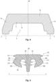
- the gasket 200 includes an annular base 202 disposed about a gasket axis C--C which extends parallel to the coupling axis A--A in the assembly 10.
- a central flange 204 can be an elongate member that extends from the annular base toward the gasket axis C--C and is generally disposed in or about a central plane perpendicular the gasket axis and parallel to the medial plane MP.
- Symmetrically formed and spaced oppositely about the central flange 204 are a pair of side flanges 206a, 206b.
- Each side flange 206a, 206b includes a sealing lip 208a, 208b for gripping and/or forming a fluid tight seal with the outer surface of an inserted pipe end.
- a sealing lip 208a, 208b for gripping and/or forming a fluid tight seal with the outer surface of an inserted pipe end.
- the internal surfaces of the gasket 200 can include a flex point 210a, 210b formed between the central flange 204 and side flanges 206a, 206b to facilitate collapse of the flanges upon pipe insertion.
- each of the first and second side flanges 206a, 206b can have an inner surface 212a, 212b contiguous with the central flange 204 which defines the flex points 210a, 210b.
- the inner surfaces 212a, 212b between the flex points and the central flange 204 can define a positive-slope transition portion between the sealing lips 208a, 208b and the central flange 204 which allows the side flanges 206a, 206b to fold in a desired manner.
- the gasket 200 also includes structures that facilitate its contact with the interior surface of the housing 12.
- Each of the side flanges 206a, 206b can include a buttress 214a, 214b which extends axially in the direction of the gasket axis C--C toward the housing interior wall or surface 13b.
- Each buttress 214a, 214b extends axially from the side flanges 206a, 206b and has a tapering configuration to a terminal preferably radiused end.
- the buttresses 214a, 214b act against the interior surface 13b of the housing segments 12 to resist axial gasket displacement and facilitate gasket expansion within the housing 12 upon insertion of the pipe end.
- Each of the first and second side flanges 206a, 206b can have an outer surface 212c, 212d that includes a heel 213a, 213b, which assists in guiding axial insertion of the pipe end, maintains contact between the pipe end and the sealing lip 208a, 208b, and also acts against the interior surface 13b of the housing 12 to center the gasket 200 within the housing 12.
- the heels 213a, 213b are the outermost edge of the sealing lips 208a, 208b axially spaced from the central flange 204 to define the entrance perimeter through which a pipe end is inserted into the gasket 200.
- Each of the heels 213a, 213b have a profile defined by portions of the outer surfaces 212c, 212d that are disposed at right angles; however, an acute angle can be utilized.
- the heel 213a, 213b lies against the pipe end outer surface and can present an abutment to the interior surface 13b of the housing to keep the gasket 200 centered within the housing 12.
- the fastener 20 is shown with the nut 20b threaded on the leading end of the bolt such that the clamp segments 12a, 12b are attached and manually spaced apart or opened to the maximum extent. Even with the segments at their maximized spacing, the gasket 200 remains contained within one or more cavities 19 of the housing 12 thereby preventing unintended separation of the gasket 200 from the housing 12 prior to pipe end insertion. Moreover, at the fully open configuration of the housing 12, the gasket 200 is free to move within the containment volume of the housing 12.
- the gasket 200 can come to rest in contact with the interior of the housing proximate the fastening tabs 16a, 16b of the two clamp segments 12a, 12b of the housing 12.
- the gasket 200 can come to rest anywhere within any one or more of the cavities 19a and 19b of the clamp segments.
- the cavity 19c and the gasket 200 can define chamber 216.
- the sealing lips 208a, 208b and in particular their heels 213a, 213b can be within the insertion boundary 11 for receipt of a pipe end.
- the gasket 200 can be located and contained within the housing with at least one coupling segment suspended about the gasket 200.
- the bridge segment 12c can be suspended about the gasket 200 with its interior surface 13 spaced from the external annular surface of the gasket 200 and the cavity 19 unfilled therebetween.
- FIGS. 10-15 illustrate the assembly of a pipe joint using the pre-assembled coupling assembly 10. Shown in FIG.
- FIG. 10 is a cross-sectional detailed view of the coupling 10 taken at the bisecting plane through the bridge segment 12c suspended above the gasket 200 and with the manually manipulated clamp segments 12a, 12b (not shown); two pipe ends 5a, 5b are positioned for axial insertion into the insertion boundary 11.
- the gasket 200 be supported on at least one of the two clamp segments 12a, 12b (not shown) in a manner as previously described with its sealing lips 208a, 208b positioned within the insertion boundary 11 for receipt of the pipe ends 5a, 5b.
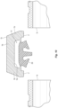
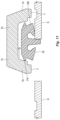
- FIG. 11 shows a first pipe end 5b inserted into the coupling 10.
- the pipe end 5b impacts the side flange 206b causing it to deflect inward toward the central flange 204.
- the pipe insertion causes the gasket 200 to shift sideways such that the buttress 214a, opposite the deflected side flange 206b, impacts the interior surface 13b of the lateral portion 15b of the segment 12c.
- the interaction between the buttress 214a and the interior surface 13b ensures the gasket 200 is retained within the housing 12, and facilitates centering of the gasket within the housing 12.
- the pipe insertion causes the gasket 200 to expand such that the outer peripheral surface of the gasket is expanded, such that it moves closer to the interior surface 13b of the medial portion thereby reducing the size of chamber 216.
- the gription of the sealing lip 208b grabs pipe 5b.
- the gription of the sealing lip 208b can be sufficient to retain the pre-assembled coupling in position on the pipe 5b when the pipe 5b is disposed at various angular orientations relative to a horizontal plane and the pipe axis. Accordingly, the sealing lips 208a, 208b can have an interference fit with the pipes 5a. In FIG.
- the second pipe end 5a has been inserted, the gasket 200 recenters and further expands within the chamber 216 and bringing the opposite buttress 214b into contact with the interior surface 13b of the adjacent lateral portion 15c.
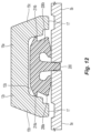
- the central flange 204 extends between the pipe ends 5a, 5b, and the sealing lips 208a, 208b grip the outer surface of the pipe ends 5a, 5b as seen for example in FIG. 13 .
- Shown in FIG. 14 is the coupling 10 being tightened about the pipe ends with the pipe engagement members 17 being brought into engagement with the pipe grooves.
- the gasket 200 is further compressed within the chamber 216 such that the heels 213a, 213b are brought into engagement with the outer pipe surface and the buttresses 214a, 214b are deflected toward the pipe.
- the fastener 20 is fully tightened to bring the fastener tabs 16 of the clamp segments 12a, 12b together and enclose the gasket 200 about the pipe ends 5a, 5b such that the sealing lips 208a, 208b fully fold to form a fluid tight seal about the pipe ends 5a, 5b.
- the pipe engagement members 17 are engaged within the outer pipe grooves, such as with complete contact between the base of the groove and the engagement member 17 to form a rigid pipe joint.
- the pre-assembled coupling 10 provides a method for forming a rigid pipe joint in which a gasket is suitably located and contained within the coupling housing by manual manipulation of the clamp segments of the housing prior to insertion of the pipe ends to be joined.
- the pre-assembled coupling can provide that the pipe ends upon insertion are gripped and retained by the gasket prior to tightening of the single clenchable fastener.
- the pre-assembled coupling can provide for expansion of the gasket upon pipe insertion and can utilize a single clenchable fastener to form a fluid tight seal between the gasket and the inserted pipe ends.
- references to at least one of a conjunctive list of terms may be construed as an inclusive OR to indicate any of a single, more than one, and all of the described terms.
- a reference to "at least one of 'A' and 'B'” can include only 'A', only 'B', as well as both 'A' and 'B'.
- Such references used in conjunction with “comprising" or other open terminology can include additional items.
Landscapes
- Engineering & Computer Science (AREA)
- General Engineering & Computer Science (AREA)
- Mechanical Engineering (AREA)
- Physics & Mathematics (AREA)
- Fluid Mechanics (AREA)
- Gasket Seals (AREA)
- Joining Of Building Structures In Genera (AREA)
Claims (12)
- Vormontierte Rohrkupplung (10) zum Einsetzen von Rohrenden, die Folgendes umfasst:eine Dichtung (200) zur Bildung einer Versiegelung um eine Rohrverbindung, wobei die Dichtung (200) eine ringförmige Basis (202) aufweist, die um eine Dichtungsachse angeordnet ist, einen zentralen Flansch (204), der sich von der ringförmigen Basis (202) in Richtung der Dichtungsachse (C-C) erstreckt, wobei der zentrale Flansch (204) um eine zentrale Ebene senkrecht zur Dichtungsachse (C-C) angeordnet ist, einen ersten Seitenflansch (206a), der von dem zentralen Flansch (204) beabstandet ist und sich von der ringförmigen Basis (202) in Richtung der Dichtungsachse (C-C) erstreckt, wobei der erste Seitenflansch (206a) eine erste Dichtlippe (208a) aufweist, einen zweiten Seitenflansch (206b), der von dem zentralen Flansch (204) gegenüber dem ersten Seitenflansch (206a) beabstandet ist und sich von der ringförmigen Basis (202) in Richtung der Dichtungsachse (C-C) erstreckt, wobei der zweite Seitenflansch (206b) eine zweite Dichtlippe (208b) aufweist; undein Gehäuse, das die Dichtung (200) umgibt, wobei das Gehäuse drei Segmente (12a,12b,12c) aufweist, wobei die drei Segmente (12a,12b,12c) aufeinanderfolgend miteinander gekoppelt sind, um eine Einführbegrenzung (11) zu definieren, wobei die Einführbegrenzung (11) eine minimale Spannweite, die größer als ein Durchmesser der Rohrenden ist, und eine maximale Spannweite, die kleiner als ein Außendurchmesser der Dichtung (200) ist, aufweist, wobei jedes Segment (12a,12b,12c) einen Hohlraum (19a,19b,19c) definiert und eine Wand (13) mit einer Außenfläche und einer Innenfläche aufweist, die Innenfläche symmetrisch um eine Mittelebene angeordnet ist, die Wand (13) einen mittleren Abschnitt (15a), einen ersten seitlichen Abschnitt (15b), der mit dem mittleren Abschnitt (15a) verbunden ist, und einen zweiten seitlichen Abschnitt (15c), der mit dem mittleren Abschnitt (15a) verbunden ist, aufweist, wobei der zweite seitliche Abschnitt (15c) von dem ersten seitlichen Abschnitt (15b) entlang der Verbindungsachse beabstandet ist, so dass die Innenfläche den Hohlraum (19a,19b,19c) definiert, wobei der erste und der zweite seitliche Abschnitt (15b.15c) Rohreingriffselemente aufweisen;ein erstes Segment (12c) der drei Segmente, das eine erste Halterung (18) aufweist, die sich seitlich in einer ersten Richtung von der Wand (13) erstreckt, wobei die erste Halterung (18) eine Vielzahl von ersten Seitenwänden aufweist, die einen ersten Umfang einer ersten Öffnung (22) definieren, und eine zweite Halterung (18), die sich seitlich in einer zweiten Richtung von der Wand (13) erstreckt, wobei die zweite Halterung (18) eine Vielzahl von zweiten Seitenwänden aufweist, die einen zweiten Umfang einer zweiten Öffnung (22) definieren, wobei das erste Segment einen oberen Boden (40a) aufweist, der den ersten Umfang der ersten Öffnung begrenzt;ein zweites Segment (12b) der drei Segmente mit einem ersten Haken (14), der in der ersten Öffnung (22) angeordnet ist, und einer ersten Befestigungslasche (16), die eine erste Befestigungsöffnung definiert;ein drittes Segment (12a) der drei Segmente mit einem zweiten Haken (14), der in der zweiten Öffnung (22) angeordnet ist, und einer zweiten Befestigungslasche (16), die eine zweite Befestigungsöffnung definiert;ein Befestigungselement (20), das durch die erste Befestigungsöffnung und die zweite Befestigungsöffnung hindurch angeordnet ist, und wobei sich die Dichtung (200) in einer beabstandeten Konfiguration der Segmente (12a,12b,12c) und des Befestigungselements (20) innerhalb eines oder mehrerer der Hohlräume (19a,19b,19c) befindet und sich frei im Gehäuse bewegen kann,wobei der erste Haken (14) einen Schenkel (30) und eine Spitze (32) aufweist, wobei der Schenkel (30) eine Innenfläche (30a) und eine Außenfläche (30b) aufweist, wobei sich die Außenfläche (30b) zwischen der Wand (13) und der Spitze (32) erstreckt, wobei die Spitze (32) eine erste Seite und eine beabstandete zweite Seite aufweist, der erste Haken (14) und die erste Öffnung (22) eine Verriegelung mit (i) einer ersten Konfiguration, in der eine untere Haltefläche (32b) der Spitze dem oberen Boden (40a) der ersten Halterung mit einem Spalt zwischen der Spitze und dem oberen Boden gegenübersteht und die Innenfläche (30a) des Schenkels einen Linienkontakt mit der Innenwand der ersten Halterung (18) bildet, und (ii) einer zweiten Konfiguration, in der der Spalt verringert ist, bilden.
- Die vormontierte Rohrkupplung (10) nach Anspruch 1, umfasst Folgendes:das erste Segment (12c) ist ein Brückensegment;das zweite Segment (12b) ist ein erstes Schnallensegment; das dritte Segment (12a) ist ein zweites Schnallensegment; unddas Befestigungselement (20) weist einen ersten Befestigungsabschnitt auf, der von einem zweiten Befestigungsabschnitt beabstandet ist, wobei die erste Befestigungslasche (16) des ersten Schnallensegments (12b) manuell betätigt wird, um den ersten Befestigungsabschnitt zu berühren, und die zweite Lasche (16) des zweiten Schnallensegments (12a) manuell betätigt wird, um den zweiten Befestigungsabschnitt zu berühren, der Hohlraum (19a) des Brückensegments (12c) ist von der ringförmigen Oberfläche der Dichtung (200) beabstandet, wobei mindestens einer des Hohlraums (19b) des ersten Schnallensegments (12b) und des Hohlraums (19c) des zweiten Schnallensegments (12a) die ringförmige Oberfläche der Dichtung (200) enthält, um die erste Dichtlippe (208a) und die zweite Dichtlippe (208b) innerhalb der Einführbegrenzung (11) zu positionieren.
- Die vormontierte Rohrkupplung (10) nach Anspruch 1, umfasst Folgendes:
eine erste Führung (42a), die auf dem Boden (40) angeordnet ist, und eine zweite Führung (42b), die auf dem Boden (40) angeordnet ist. - Die vormontierte Rohrkupplung (10) nach Anspruch 1, umfasst Folgendes:
der Hohlraum (19a) des ersten Segments (12c) ist um etwa 90 Grad versetzt; und der Hohlraum (19b) des zweiten Segments (12b) und der Hohlraum (19a) des dritten Segments (12a) sind jeweils um etwa 135 Grad versetzt. - Die vormontierte Rohrkupplung (10) nach Anspruch 1, wobei:
das Befestigungselement (20) ein einheitliches Befestigungselement ist und die erste Befestigungslasche (16) des zweiten Segments (12b) und die zweite Befestigungslasche (16) des dritten Segments (12a) verbindet. - Die vormontierte Rohrkupplung (10) nach Anspruch 1, umfasst Folgendes:eine erste Innenfläche der Dichtung (200), die einen ersten Biegepunkt und einen ersten positiv geneigten Übergangsbereich zwischen der ersten Dichtlippe (208a) und dem zentralen Flansch (204) definiert;eine zweite Innenfläche der Dichtung (200), die einen zweiten Biegepunkt und einen zweiten positiv geneigten Übergangsbereich zwischen der zweiten Dichtlippe (208b) und dem zentralen Flansch (204) definiert;eine erste Stütze (214a), die von dem ersten Seitenflansch (206a) entlang der Dichtungsachse (C-C) in Richtung des ersten seitlichen Abschnitts (15b) der Gehäusewand (13) vorsteht; undeine zweite Stütze (214b), die von dem zweiten Seitenflansch (206b) entlang der Dichtungsachse (C-C) in Richtung des zweiten seitlichen Abschnitts (15c) der Gehäusewand (13) vorsteht.
- Die vormontierte Rohrkupplung (10) nach Anspruch 1, umfasst Folgendes:
mindestens ein Segment (12a,12b,12c) der drei Segmente ist um die Dichtung (200) herum aufgehängt, so dass eine Kompressionskammer zwischen einer Außenseite der ringförmigen Basis (202) der Dichtung (200) und einer Innenfläche des mindestens einen Segments (12a, 12b, 12c) definiert ist. - Die vormontierte Rohrkupplung (10) nach Anspruch 1, umfasst Folgendes:
die ringförmige Basis (202) der Dichtung (200) dehnt sich innerhalb des Hohlraums (19a,19b,19c) eines jeden Segments (12a,12b,12c) beim Einführen eines Rohrendes in die Einführbegrenzung (11) aus. - Die vormontierte Rohrkupplung (10) nach Anspruch 1, umfasst Folgendes:
die erste Dichtlippe (208a) und die zweite Dichtlippe (208b), die sich innerhalb der Einführungsbegrenzung (11) befinden, um die jeweiligen Enden eines jeden Rohrpaares vor dem Festziehen des Befestigungselements zu greifen. - Die vormontierte Rohrkupplung (10) nach Anspruch 1, umfasst Folgendes:
die erste Dichtlippe (208a) hält die vormontierte Kupplung (10) beim Einführen des Rohrendes in die Einführungsbegrenzung (11) an einem Rohrende fest. - Verfahren zum Verbinden eines Paares von Rohrenden in einer axialen Anordnung mit einer vormontierten Kupplung (10) nach einem der Ansprüche 1 bis 10, wobei das Verfahren Folgendes umfasst:manuelles Manipulieren der Vielzahl miteinander verbundener Segmente (12a,12b,12c), um eine Einführungsbegrenzung (11) auf jeder Seite des Gehäuses zu definieren, die die Kupplungsachse umgibt, wobei die Einführungsbegrenzung (11) eine minimale Spannweite hat, die größer als ein Durchmesser der Rohrenden ist, und eine maximale Spannweite, die kleiner als ein Außendurchmesser der Dichtung (200) ist, und wobei jedes Segment (12a,12b,12c) einen Hohlraum (19a,19b,19c) definiert und in einer beabstandeten Konfiguration der Segmente (12a,12b,12c) und des Befestigungselements liegt, die Dichtung (200) befindet sich innerhalb eines oder mehrerer der Hohlräume (19a,19b,19c) und kann sich frei im Gehäuse bewegen;axiales Einführen eines der Rohrenden durch die Einführungsbegrenzung (11) auf jeder Seite des Gehäuses; Ergreifen der Rohrenden mit den Dichtlippen (208a,208b); undEinstellen eines der Befestigungsmechanismen, so dass die Rohreingriffselemente (17) mit den Rohrenden in Eingriff kommen und die Dichtlippen (208a,208b) eine flüssigkeitsdichte Versiegelung um die Rohrenden bilden.
- Das Verfahren nach Anspruch 11, umfasst Folgendes: Ausdehnen der ringförmigen Basis (202) der Dichtung (200) innerhalb des Hohlraums (19a,19b,19c) eines jeden Segments (12a,12b,12c) beim Einführen eines Rohrendes in die Einführbegrenzung (11).
Applications Claiming Priority (2)
| Application Number | Priority Date | Filing Date | Title |
|---|---|---|---|
| US201762512452P | 2017-05-30 | 2017-05-30 | |
| PCT/US2018/034915 WO2018222605A1 (en) | 2017-05-30 | 2018-05-29 | Pre-assembled pipe coupling with manually manipulatable segments |
Publications (2)
| Publication Number | Publication Date |
|---|---|
| EP3631271A1 EP3631271A1 (de) | 2020-04-08 |
| EP3631271B1 true EP3631271B1 (de) | 2024-01-10 |
Family
ID=62621092
Family Applications (1)
| Application Number | Title | Priority Date | Filing Date |
|---|---|---|---|
| EP18731723.5A Active EP3631271B1 (de) | 2017-05-30 | 2018-05-29 | Vormontierte rohrkupplung mit manuell manipulierbaren segmenten |
Country Status (8)
| Country | Link |
|---|---|
| US (4) | US11313496B2 (de) |
| EP (1) | EP3631271B1 (de) |
| CN (1) | CN110678686A (de) |
| AU (1) | AU2018277526B2 (de) |
| CA (1) | CA3063584A1 (de) |
| MY (1) | MY203064A (de) |
| TW (1) | TWI726211B (de) |
| WO (1) | WO2018222605A1 (de) |
Families Citing this family (13)
| Publication number | Priority date | Publication date | Assignee | Title |
|---|---|---|---|---|
| CA3063579A1 (en) | 2017-05-30 | 2018-12-06 | Tyco Fire Products Lp | Pre-assembled pipe coupling with an insertion boundary for axial receipt of pipe ends |
| TWI726211B (zh) | 2017-05-30 | 2021-05-01 | 美商泰科防火產品有限合夥公司 | 用於插入管端的預裝配式管聯接器及用預裝配式聯接器將一對軸向佈置的管端連結之方法 |
| GB2588169A (en) | 2019-10-11 | 2021-04-21 | Gall Thomson Environmental Ltd | Securing device |
| US11781683B2 (en) * | 2019-11-15 | 2023-10-10 | Victaulic Company | Shrouded coupling |
| CN111536115A (zh) * | 2020-05-12 | 2020-08-14 | 芜湖清柏白露智能信息科技有限公司 | 一种夹持组件及其应用 |
| USD1053319S1 (en) * | 2020-11-13 | 2024-12-03 | Victaulic Company | Pipe coupling |
| USD1021015S1 (en) * | 2020-11-13 | 2024-04-02 | Victaulic Company | Pipe coupling |
| KR102351804B1 (ko) * | 2020-12-17 | 2022-01-17 | 주식회사 후손 | 파이프 연결용 클램프 |
| USD1066603S1 (en) * | 2021-07-07 | 2025-03-11 | Mann Teknik Ab | Packing ring for tubes and pipes |
| JP7481013B2 (ja) | 2021-08-25 | 2024-05-10 | 株式会社Tozen | 管継手 |
| WO2023055760A1 (en) | 2021-10-01 | 2023-04-06 | Victaulic Company | Enhanced stability gasket and coupling |
| USD1101906S1 (en) * | 2023-08-29 | 2025-11-11 | Shanghai Vision Mechanical Joint Co., Ltd. | Quick-fitting pipe coupler |
| CN117307718A (zh) * | 2023-11-14 | 2023-12-29 | 上海威逊机械连接件有限公司 | 一种管件接头密封件及管件连接结构 |
Family Cites Families (37)
| Publication number | Priority date | Publication date | Assignee | Title |
|---|---|---|---|---|
| US3351352A (en) * | 1962-02-27 | 1967-11-07 | Victaulic Co Of America | Gasket for pipe joint |
| GB1129246A (en) * | 1966-07-29 | 1968-10-02 | Binder Engineering Company Ltd | Pipe clip |
| US3464722A (en) * | 1968-04-19 | 1969-09-02 | Sam Larkin | Pipe coupling having segmented clamping means |
| US3964773A (en) * | 1974-09-13 | 1976-06-22 | Mercury Metal Products, Inc. | Anti-emission exhaust pipe joint and clamp therefor |
| US4225160A (en) * | 1978-02-27 | 1980-09-30 | Exxon Production Research Company | Low friction remotely operable clamp type pipe connector |
| US4702499A (en) * | 1986-10-21 | 1987-10-27 | Victaulic Company Of America | Hingeable segmented pipe couplings |
| US4915418A (en) * | 1989-05-19 | 1990-04-10 | Urdan Industries (Usa), Inc. | Hinged pipe coupling |
| US5018768A (en) | 1990-07-19 | 1991-05-28 | Quikcoup, Incorporated | Pipe coupling hinge |
| EP0571687B1 (de) * | 1992-05-21 | 1995-08-16 | Heinrich Fend | Vorrichtung zum Gegeneinanderpressen von zwei konischen Flanschen einer Rohrverbindung |
| US5282654A (en) * | 1993-04-26 | 1994-02-01 | Quikcoup, Inc. | Pipe coupling sleeve |
| US5509702A (en) * | 1994-08-23 | 1996-04-23 | Eg&G Pressure Science, Inc. | Low distortion pipe coupling device |
| US5758907A (en) * | 1996-07-26 | 1998-06-02 | Victaulic Company Of America | Mis-adjustment limiting segmented pipe coupling |
| ATE239550T1 (de) * | 1998-03-06 | 2003-05-15 | Buechi Lab Tech | Verbindungselement zum verbinden benachbarter anschlusselemente an rohren und/oder behältermündungen, insbesondere an laborgeräten |
| US6139069A (en) * | 1998-08-24 | 2000-10-31 | Central Sprinkler Corporation | Universal mechanical coupling with interfitting ends |
| AUPP863899A0 (en) | 1999-02-12 | 1999-03-11 | Mining Supplies Australia Pty Ltd | Interlocking pipe coupling |
| US6672139B2 (en) * | 1999-06-28 | 2004-01-06 | Inflow Products, Inc. | Leak testing device and a coupling therefor |
| CN101427063A (zh) * | 2004-03-26 | 2009-05-06 | 维克托里克公司 | 具有楔形圆周槽的管道 |
| US7086131B2 (en) * | 2004-05-14 | 2006-08-08 | Victaulic Company | Deformable mechanical pipe coupling |
| US7712796B2 (en) * | 2004-05-14 | 2010-05-11 | Victaulic Company | Deformable mechanical pipe coupling |
| DE102005052517B4 (de) * | 2005-11-03 | 2010-01-21 | Schwing Gmbh | Rohrleitungskupplung mit einem Dichtungsring und Rohrleitungssystem für die Förderung von Dickstoffen |
| ES2524825T3 (es) * | 2009-10-27 | 2014-12-12 | Tyco Fire Products Lp | Sistemas y métodos para acoplamientos de bisagra |
| PH12012500810A1 (en) | 2009-10-27 | 2012-11-26 | Tyco Fire Products Lp | Systems and methods for pipe couplings |
| KR20110060832A (ko) * | 2009-11-30 | 2011-06-08 | 이하라 사이언스 가부시키가이샤 | 결합링 |
| CN103299117B (zh) * | 2010-07-10 | 2015-04-08 | 阿吉特·辛格·吉尔 | 弧形快速联接器 |
| JP2012037050A (ja) * | 2010-07-12 | 2012-02-23 | Ihara Science Corp | 流体システム |
| IL209938A (en) * | 2010-12-12 | 2014-06-30 | Eliezer Krausz | Mounting clamp with bushing for clamping element |
| US8556302B2 (en) * | 2011-04-05 | 2013-10-15 | Victaulic Company | Pivoting pipe coupling having a movable gripping body |
| US20140132000A1 (en) * | 2011-06-15 | 2014-05-15 | Amiad Water Systems Ltd. | Tubular elements coupling |
| WO2014135649A1 (en) * | 2013-03-07 | 2014-09-12 | Tyco Fire & Security Gmbh | Three piece pipe coupling |
| KR101575896B1 (ko) * | 2014-06-09 | 2015-12-08 | 주식회사 서원기술 | 배관용 압착체결구 |
| DE102016103703A1 (de) * | 2016-03-02 | 2017-09-07 | Norma Germany Gmbh | Profilschelle |
| TWI726211B (zh) * | 2017-05-30 | 2021-05-01 | 美商泰科防火產品有限合夥公司 | 用於插入管端的預裝配式管聯接器及用預裝配式聯接器將一對軸向佈置的管端連結之方法 |
| CA3063579A1 (en) * | 2017-05-30 | 2018-12-06 | Tyco Fire Products Lp | Pre-assembled pipe coupling with an insertion boundary for axial receipt of pipe ends |
| US11448346B2 (en) * | 2018-09-28 | 2022-09-20 | ASC Engineered Solutions, LLC | Pipe coupling |
| CN109442108B (zh) * | 2018-12-14 | 2024-05-03 | 山东莱德机械有限公司 | 一种快连卡箍 |
| CN110067905B (zh) * | 2019-05-30 | 2023-12-08 | 山东亿佰通机械股份有限公司 | 三通卡箍及具有该卡箍的接头连接预制件 |
| CN110230735A (zh) * | 2019-06-26 | 2019-09-13 | 山东亿佰通机械股份有限公司 | 夹接头及具有该夹接头的联接件 |
-
2018
- 2018-05-29 TW TW107118270A patent/TWI726211B/zh active
- 2018-05-29 WO PCT/US2018/034915 patent/WO2018222605A1/en not_active Ceased
- 2018-05-29 MY MYPI2019006941A patent/MY203064A/en unknown
- 2018-05-29 EP EP18731723.5A patent/EP3631271B1/de active Active
- 2018-05-29 US US16/616,145 patent/US11313496B2/en active Active
- 2018-05-29 CN CN201880035621.XA patent/CN110678686A/zh active Pending
- 2018-05-29 AU AU2018277526A patent/AU2018277526B2/en active Active
- 2018-05-29 CA CA3063584A patent/CA3063584A1/en active Pending
-
2022
- 2022-03-11 US US17/692,506 patent/US11754209B2/en active Active
-
2023
- 2023-08-10 US US18/447,634 patent/US12038109B2/en active Active
-
2024
- 2024-06-10 US US18/738,886 patent/US12331855B2/en active Active
Also Published As
| Publication number | Publication date |
|---|---|
| WO2018222605A1 (en) | 2018-12-06 |
| AU2018277526B2 (en) | 2023-12-21 |
| US20230383877A1 (en) | 2023-11-30 |
| US20220196191A1 (en) | 2022-06-23 |
| MY203064A (en) | 2024-06-06 |
| US11754209B2 (en) | 2023-09-12 |
| US20200088327A1 (en) | 2020-03-19 |
| TW201908638A (zh) | 2019-03-01 |
| TWI726211B (zh) | 2021-05-01 |
| CA3063584A1 (en) | 2018-12-06 |
| US12331855B2 (en) | 2025-06-17 |
| CN110678686A (zh) | 2020-01-10 |
| US11313496B2 (en) | 2022-04-26 |
| AU2018277526A1 (en) | 2019-11-21 |
| US12038109B2 (en) | 2024-07-16 |
| EP3631271A1 (de) | 2020-04-08 |
| US20240328547A1 (en) | 2024-10-03 |
Similar Documents
| Publication | Publication Date | Title |
|---|---|---|
| US12038109B2 (en) | Pre-assembled pipe coupling with manually manipulatable segments | |
| US11692653B2 (en) | Pre-assembled pipe coupling with an insertion boundary for axial receipt of pipe ends | |
| US20200332934A1 (en) | Quick Installation Coupling | |
| KR101989884B1 (ko) | 이동 가능한 파지체를 갖는 피벗형 파이프 커플링 | |
| EP2492563B1 (de) | Klemme für Leitung oder Kabel | |
| JP7732056B2 (ja) | 管接続部の離脱防止構造 | |
| CN108291662B (zh) | 具有定中心支承突出部的阀联接件 | |
| JPH0451711B2 (de) | ||
| US9731156B2 (en) | Fixing bracket of sprinkler | |
| JP4042609B2 (ja) | ウォーム駆動のホースクリップ | |
| KR20150055608A (ko) | 주름관 연결 기구 | |
| KR20150031841A (ko) | 주름관 연결 기구 | |
| KR102966818B1 (ko) | 배관 지지장치 | |
| JPH0132927Y2 (de) |
Legal Events
| Date | Code | Title | Description |
|---|---|---|---|
| STAA | Information on the status of an ep patent application or granted ep patent |
Free format text: STATUS: UNKNOWN |
|
| STAA | Information on the status of an ep patent application or granted ep patent |
Free format text: STATUS: THE INTERNATIONAL PUBLICATION HAS BEEN MADE |
|
| PUAI | Public reference made under article 153(3) epc to a published international application that has entered the european phase |
Free format text: ORIGINAL CODE: 0009012 |
|
| STAA | Information on the status of an ep patent application or granted ep patent |
Free format text: STATUS: REQUEST FOR EXAMINATION WAS MADE |
|
| 17P | Request for examination filed |
Effective date: 20191216 |
|
| AK | Designated contracting states |
Kind code of ref document: A1 Designated state(s): AL AT BE BG CH CY CZ DE DK EE ES FI FR GB GR HR HU IE IS IT LI LT LU LV MC MK MT NL NO PL PT RO RS SE SI SK SM TR |
|
| AX | Request for extension of the european patent |
Extension state: BA ME |
|
| DAV | Request for validation of the european patent (deleted) | ||
| DAX | Request for extension of the european patent (deleted) | ||
| STAA | Information on the status of an ep patent application or granted ep patent |
Free format text: STATUS: EXAMINATION IS IN PROGRESS |
|
| 17Q | First examination report despatched |
Effective date: 20211213 |
|
| GRAP | Despatch of communication of intention to grant a patent |
Free format text: ORIGINAL CODE: EPIDOSNIGR1 |
|
| STAA | Information on the status of an ep patent application or granted ep patent |
Free format text: STATUS: GRANT OF PATENT IS INTENDED |
|
| INTG | Intention to grant announced |
Effective date: 20231005 |
|
| RAP3 | Party data changed (applicant data changed or rights of an application transferred) |
Owner name: TYCO FIRE PRODUCTS LP |
|
| GRAS | Grant fee paid |
Free format text: ORIGINAL CODE: EPIDOSNIGR3 |
|
| GRAA | (expected) grant |
Free format text: ORIGINAL CODE: 0009210 |
|
| STAA | Information on the status of an ep patent application or granted ep patent |
Free format text: STATUS: THE PATENT HAS BEEN GRANTED |
|
| AK | Designated contracting states |
Kind code of ref document: B1 Designated state(s): AL AT BE BG CH CY CZ DE DK EE ES FI FR GB GR HR HU IE IS IT LI LT LU LV MC MK MT NL NO PL PT RO RS SE SI SK SM TR |
|
| REG | Reference to a national code |
Ref country code: GB Ref legal event code: FG4D |
|
| REG | Reference to a national code |
Ref country code: CH Ref legal event code: EP |
|
| REG | Reference to a national code |
Ref country code: DE Ref legal event code: R096 Ref document number: 602018063960 Country of ref document: DE |
|
| REG | Reference to a national code |
Ref country code: IE Ref legal event code: FG4D |
|
| P01 | Opt-out of the competence of the unified patent court (upc) registered |
Effective date: 20240102 |
|
| REG | Reference to a national code |
Ref country code: LT Ref legal event code: MG9D |
|
| REG | Reference to a national code |
Ref country code: NL Ref legal event code: MP Effective date: 20240110 |
|
| REG | Reference to a national code |
Ref country code: AT Ref legal event code: MK05 Ref document number: 1649134 Country of ref document: AT Kind code of ref document: T Effective date: 20240110 |
|
| PG25 | Lapsed in a contracting state [announced via postgrant information from national office to epo] |
Ref country code: NL Free format text: LAPSE BECAUSE OF FAILURE TO SUBMIT A TRANSLATION OF THE DESCRIPTION OR TO PAY THE FEE WITHIN THE PRESCRIBED TIME-LIMIT Effective date: 20240110 |
|
| PG25 | Lapsed in a contracting state [announced via postgrant information from national office to epo] |
Ref country code: NL Free format text: LAPSE BECAUSE OF FAILURE TO SUBMIT A TRANSLATION OF THE DESCRIPTION OR TO PAY THE FEE WITHIN THE PRESCRIBED TIME-LIMIT Effective date: 20240110 |
|
| PG25 | Lapsed in a contracting state [announced via postgrant information from national office to epo] |
Ref country code: IS Free format text: LAPSE BECAUSE OF FAILURE TO SUBMIT A TRANSLATION OF THE DESCRIPTION OR TO PAY THE FEE WITHIN THE PRESCRIBED TIME-LIMIT Effective date: 20240510 |
|
| PG25 | Lapsed in a contracting state [announced via postgrant information from national office to epo] |
Ref country code: LT Free format text: LAPSE BECAUSE OF FAILURE TO SUBMIT A TRANSLATION OF THE DESCRIPTION OR TO PAY THE FEE WITHIN THE PRESCRIBED TIME-LIMIT Effective date: 20240110 |
|
| PG25 | Lapsed in a contracting state [announced via postgrant information from national office to epo] |
Ref country code: GR Free format text: LAPSE BECAUSE OF FAILURE TO SUBMIT A TRANSLATION OF THE DESCRIPTION OR TO PAY THE FEE WITHIN THE PRESCRIBED TIME-LIMIT Effective date: 20240411 |
|
| PG25 | Lapsed in a contracting state [announced via postgrant information from national office to epo] |
Ref country code: RS Free format text: LAPSE BECAUSE OF FAILURE TO SUBMIT A TRANSLATION OF THE DESCRIPTION OR TO PAY THE FEE WITHIN THE PRESCRIBED TIME-LIMIT Effective date: 20240410 Ref country code: HR Free format text: LAPSE BECAUSE OF FAILURE TO SUBMIT A TRANSLATION OF THE DESCRIPTION OR TO PAY THE FEE WITHIN THE PRESCRIBED TIME-LIMIT Effective date: 20240110 |
|
| PG25 | Lapsed in a contracting state [announced via postgrant information from national office to epo] |
Ref country code: ES Free format text: LAPSE BECAUSE OF FAILURE TO SUBMIT A TRANSLATION OF THE DESCRIPTION OR TO PAY THE FEE WITHIN THE PRESCRIBED TIME-LIMIT Effective date: 20240110 |
|
| PG25 | Lapsed in a contracting state [announced via postgrant information from national office to epo] |
Ref country code: AT Free format text: LAPSE BECAUSE OF FAILURE TO SUBMIT A TRANSLATION OF THE DESCRIPTION OR TO PAY THE FEE WITHIN THE PRESCRIBED TIME-LIMIT Effective date: 20240110 |
|
| PG25 | Lapsed in a contracting state [announced via postgrant information from national office to epo] |
Ref country code: RS Free format text: LAPSE BECAUSE OF FAILURE TO SUBMIT A TRANSLATION OF THE DESCRIPTION OR TO PAY THE FEE WITHIN THE PRESCRIBED TIME-LIMIT Effective date: 20240410 Ref country code: NO Free format text: LAPSE BECAUSE OF FAILURE TO SUBMIT A TRANSLATION OF THE DESCRIPTION OR TO PAY THE FEE WITHIN THE PRESCRIBED TIME-LIMIT Effective date: 20240410 Ref country code: LT Free format text: LAPSE BECAUSE OF FAILURE TO SUBMIT A TRANSLATION OF THE DESCRIPTION OR TO PAY THE FEE WITHIN THE PRESCRIBED TIME-LIMIT Effective date: 20240110 Ref country code: IS Free format text: LAPSE BECAUSE OF FAILURE TO SUBMIT A TRANSLATION OF THE DESCRIPTION OR TO PAY THE FEE WITHIN THE PRESCRIBED TIME-LIMIT Effective date: 20240510 Ref country code: HR Free format text: LAPSE BECAUSE OF FAILURE TO SUBMIT A TRANSLATION OF THE DESCRIPTION OR TO PAY THE FEE WITHIN THE PRESCRIBED TIME-LIMIT Effective date: 20240110 Ref country code: GR Free format text: LAPSE BECAUSE OF FAILURE TO SUBMIT A TRANSLATION OF THE DESCRIPTION OR TO PAY THE FEE WITHIN THE PRESCRIBED TIME-LIMIT Effective date: 20240411 Ref country code: ES Free format text: LAPSE BECAUSE OF FAILURE TO SUBMIT A TRANSLATION OF THE DESCRIPTION OR TO PAY THE FEE WITHIN THE PRESCRIBED TIME-LIMIT Effective date: 20240110 Ref country code: BG Free format text: LAPSE BECAUSE OF FAILURE TO SUBMIT A TRANSLATION OF THE DESCRIPTION OR TO PAY THE FEE WITHIN THE PRESCRIBED TIME-LIMIT Effective date: 20240110 Ref country code: AT Free format text: LAPSE BECAUSE OF FAILURE TO SUBMIT A TRANSLATION OF THE DESCRIPTION OR TO PAY THE FEE WITHIN THE PRESCRIBED TIME-LIMIT Effective date: 20240110 |
|
| PG25 | Lapsed in a contracting state [announced via postgrant information from national office to epo] |
Ref country code: PL Free format text: LAPSE BECAUSE OF FAILURE TO SUBMIT A TRANSLATION OF THE DESCRIPTION OR TO PAY THE FEE WITHIN THE PRESCRIBED TIME-LIMIT Effective date: 20240110 Ref country code: PT Free format text: LAPSE BECAUSE OF FAILURE TO SUBMIT A TRANSLATION OF THE DESCRIPTION OR TO PAY THE FEE WITHIN THE PRESCRIBED TIME-LIMIT Effective date: 20240510 |
|
| PG25 | Lapsed in a contracting state [announced via postgrant information from national office to epo] |
Ref country code: SE Free format text: LAPSE BECAUSE OF FAILURE TO SUBMIT A TRANSLATION OF THE DESCRIPTION OR TO PAY THE FEE WITHIN THE PRESCRIBED TIME-LIMIT Effective date: 20240110 Ref country code: PT Free format text: LAPSE BECAUSE OF FAILURE TO SUBMIT A TRANSLATION OF THE DESCRIPTION OR TO PAY THE FEE WITHIN THE PRESCRIBED TIME-LIMIT Effective date: 20240510 Ref country code: PL Free format text: LAPSE BECAUSE OF FAILURE TO SUBMIT A TRANSLATION OF THE DESCRIPTION OR TO PAY THE FEE WITHIN THE PRESCRIBED TIME-LIMIT Effective date: 20240110 Ref country code: LV Free format text: LAPSE BECAUSE OF FAILURE TO SUBMIT A TRANSLATION OF THE DESCRIPTION OR TO PAY THE FEE WITHIN THE PRESCRIBED TIME-LIMIT Effective date: 20240110 |
|
| PG25 | Lapsed in a contracting state [announced via postgrant information from national office to epo] |
Ref country code: DK Free format text: LAPSE BECAUSE OF FAILURE TO SUBMIT A TRANSLATION OF THE DESCRIPTION OR TO PAY THE FEE WITHIN THE PRESCRIBED TIME-LIMIT Effective date: 20240110 |
|
| REG | Reference to a national code |
Ref country code: DE Ref legal event code: R097 Ref document number: 602018063960 Country of ref document: DE |
|
| PG25 | Lapsed in a contracting state [announced via postgrant information from national office to epo] |
Ref country code: SM Free format text: LAPSE BECAUSE OF FAILURE TO SUBMIT A TRANSLATION OF THE DESCRIPTION OR TO PAY THE FEE WITHIN THE PRESCRIBED TIME-LIMIT Effective date: 20240110 |
|
| PG25 | Lapsed in a contracting state [announced via postgrant information from national office to epo] |
Ref country code: CZ Free format text: LAPSE BECAUSE OF FAILURE TO SUBMIT A TRANSLATION OF THE DESCRIPTION OR TO PAY THE FEE WITHIN THE PRESCRIBED TIME-LIMIT Effective date: 20240110 Ref country code: EE Free format text: LAPSE BECAUSE OF FAILURE TO SUBMIT A TRANSLATION OF THE DESCRIPTION OR TO PAY THE FEE WITHIN THE PRESCRIBED TIME-LIMIT Effective date: 20240110 |
|
| PG25 | Lapsed in a contracting state [announced via postgrant information from national office to epo] |
Ref country code: SK Free format text: LAPSE BECAUSE OF FAILURE TO SUBMIT A TRANSLATION OF THE DESCRIPTION OR TO PAY THE FEE WITHIN THE PRESCRIBED TIME-LIMIT Effective date: 20240110 |
|
| PG25 | Lapsed in a contracting state [announced via postgrant information from national office to epo] |
Ref country code: SM Free format text: LAPSE BECAUSE OF FAILURE TO SUBMIT A TRANSLATION OF THE DESCRIPTION OR TO PAY THE FEE WITHIN THE PRESCRIBED TIME-LIMIT Effective date: 20240110 Ref country code: SK Free format text: LAPSE BECAUSE OF FAILURE TO SUBMIT A TRANSLATION OF THE DESCRIPTION OR TO PAY THE FEE WITHIN THE PRESCRIBED TIME-LIMIT Effective date: 20240110 Ref country code: RO Free format text: LAPSE BECAUSE OF FAILURE TO SUBMIT A TRANSLATION OF THE DESCRIPTION OR TO PAY THE FEE WITHIN THE PRESCRIBED TIME-LIMIT Effective date: 20240110 Ref country code: EE Free format text: LAPSE BECAUSE OF FAILURE TO SUBMIT A TRANSLATION OF THE DESCRIPTION OR TO PAY THE FEE WITHIN THE PRESCRIBED TIME-LIMIT Effective date: 20240110 Ref country code: DK Free format text: LAPSE BECAUSE OF FAILURE TO SUBMIT A TRANSLATION OF THE DESCRIPTION OR TO PAY THE FEE WITHIN THE PRESCRIBED TIME-LIMIT Effective date: 20240110 Ref country code: CZ Free format text: LAPSE BECAUSE OF FAILURE TO SUBMIT A TRANSLATION OF THE DESCRIPTION OR TO PAY THE FEE WITHIN THE PRESCRIBED TIME-LIMIT Effective date: 20240110 |
|
| PLBE | No opposition filed within time limit |
Free format text: ORIGINAL CODE: 0009261 |
|
| STAA | Information on the status of an ep patent application or granted ep patent |
Free format text: STATUS: NO OPPOSITION FILED WITHIN TIME LIMIT |
|
| PG25 | Lapsed in a contracting state [announced via postgrant information from national office to epo] |
Ref country code: IT Free format text: LAPSE BECAUSE OF FAILURE TO SUBMIT A TRANSLATION OF THE DESCRIPTION OR TO PAY THE FEE WITHIN THE PRESCRIBED TIME-LIMIT Effective date: 20240110 |
|
| 26N | No opposition filed |
Effective date: 20241011 |
|
| REG | Reference to a national code |
Ref country code: CH Ref legal event code: PL |
|
| PG25 | Lapsed in a contracting state [announced via postgrant information from national office to epo] |
Ref country code: IT Free format text: LAPSE BECAUSE OF FAILURE TO SUBMIT A TRANSLATION OF THE DESCRIPTION OR TO PAY THE FEE WITHIN THE PRESCRIBED TIME-LIMIT Effective date: 20240110 |
|
| PG25 | Lapsed in a contracting state [announced via postgrant information from national office to epo] |
Ref country code: MC Free format text: LAPSE BECAUSE OF FAILURE TO SUBMIT A TRANSLATION OF THE DESCRIPTION OR TO PAY THE FEE WITHIN THE PRESCRIBED TIME-LIMIT Effective date: 20240110 |
|
| PG25 | Lapsed in a contracting state [announced via postgrant information from national office to epo] |
Ref country code: LU Free format text: LAPSE BECAUSE OF NON-PAYMENT OF DUE FEES Effective date: 20240529 |
|
| PG25 | Lapsed in a contracting state [announced via postgrant information from national office to epo] |
Ref country code: MC Free format text: LAPSE BECAUSE OF FAILURE TO SUBMIT A TRANSLATION OF THE DESCRIPTION OR TO PAY THE FEE WITHIN THE PRESCRIBED TIME-LIMIT Effective date: 20240110 Ref country code: LU Free format text: LAPSE BECAUSE OF NON-PAYMENT OF DUE FEES Effective date: 20240529 Ref country code: CH Free format text: LAPSE BECAUSE OF NON-PAYMENT OF DUE FEES Effective date: 20240531 |
|
| REG | Reference to a national code |
Ref country code: BE Ref legal event code: MM Effective date: 20240531 |
|
| PG25 | Lapsed in a contracting state [announced via postgrant information from national office to epo] |
Ref country code: IE Free format text: LAPSE BECAUSE OF NON-PAYMENT OF DUE FEES Effective date: 20240529 |
|
| PG25 | Lapsed in a contracting state [announced via postgrant information from national office to epo] |
Ref country code: BE Free format text: LAPSE BECAUSE OF NON-PAYMENT OF DUE FEES Effective date: 20240531 Ref country code: SI Free format text: LAPSE BECAUSE OF FAILURE TO SUBMIT A TRANSLATION OF THE DESCRIPTION OR TO PAY THE FEE WITHIN THE PRESCRIBED TIME-LIMIT Effective date: 20240110 |
|
| PG25 | Lapsed in a contracting state [announced via postgrant information from national office to epo] |
Ref country code: FR Free format text: LAPSE BECAUSE OF NON-PAYMENT OF DUE FEES Effective date: 20240531 |
|
| PGFP | Annual fee paid to national office [announced via postgrant information from national office to epo] |
Ref country code: DE Payment date: 20250528 Year of fee payment: 8 |
|
| PG25 | Lapsed in a contracting state [announced via postgrant information from national office to epo] |
Ref country code: CY Free format text: LAPSE BECAUSE OF FAILURE TO SUBMIT A TRANSLATION OF THE DESCRIPTION OR TO PAY THE FEE WITHIN THE PRESCRIBED TIME-LIMIT; INVALID AB INITIO Effective date: 20180529 |
|
| PG25 | Lapsed in a contracting state [announced via postgrant information from national office to epo] |
Ref country code: FI Free format text: LAPSE BECAUSE OF FAILURE TO SUBMIT A TRANSLATION OF THE DESCRIPTION OR TO PAY THE FEE WITHIN THE PRESCRIBED TIME-LIMIT Effective date: 20240110 |
|
| PG25 | Lapsed in a contracting state [announced via postgrant information from national office to epo] |
Ref country code: HU Free format text: LAPSE BECAUSE OF FAILURE TO SUBMIT A TRANSLATION OF THE DESCRIPTION OR TO PAY THE FEE WITHIN THE PRESCRIBED TIME-LIMIT; INVALID AB INITIO Effective date: 20180529 |
|
| PGFP | Annual fee paid to national office [announced via postgrant information from national office to epo] |
Ref country code: GB Payment date: 20260304 Year of fee payment: 9 |