EP3631405B1 - Commande de microtome motorisé - Google Patents
Commande de microtome motorisé Download PDFInfo
- Publication number
- EP3631405B1 EP3631405B1 EP17933419.8A EP17933419A EP3631405B1 EP 3631405 B1 EP3631405 B1 EP 3631405B1 EP 17933419 A EP17933419 A EP 17933419A EP 3631405 B1 EP3631405 B1 EP 3631405B1
- Authority
- EP
- European Patent Office
- Prior art keywords
- slide
- microtome
- control unit
- handwheel
- electric motor
- Prior art date
- Legal status (The legal status is an assumption and is not a legal conclusion. Google has not performed a legal analysis and makes no representation as to the accuracy of the status listed.)
- Active
Links
Images

Classifications
-
- G—PHYSICS
- G01—MEASURING; TESTING
- G01N—INVESTIGATING OR ANALYSING MATERIALS BY DETERMINING THEIR CHEMICAL OR PHYSICAL PROPERTIES
- G01N1/00—Sampling; Preparing specimens for investigation
- G01N1/02—Devices for withdrawing samples
- G01N1/04—Devices for withdrawing samples in the solid state, e.g. by cutting
- G01N1/06—Devices for withdrawing samples in the solid state, e.g. by cutting providing a thin slice, e.g. microtome
-
- G—PHYSICS
- G01—MEASURING; TESTING
- G01N—INVESTIGATING OR ANALYSING MATERIALS BY DETERMINING THEIR CHEMICAL OR PHYSICAL PROPERTIES
- G01N1/00—Sampling; Preparing specimens for investigation
- G01N1/02—Devices for withdrawing samples
- G01N1/04—Devices for withdrawing samples in the solid state, e.g. by cutting
- G01N1/06—Devices for withdrawing samples in the solid state, e.g. by cutting providing a thin slice, e.g. microtome
- G01N2001/065—Drive details
- G01N2001/066—Drive details electric
Definitions
- the present disclosure relates to a microtome having a control unit for controlling motorized functions of the microtome.
- the present disclosure lies in the field of microtomes for producing thin sections, in which the cutting operation is performed by way of a relative movement between a cutting knife and an object.
- a drive system having a drive motor, a control unit, and a manually operation device such as a handwheel can be provided to generate the relative movement.
- Microtomes are increasingly being automated in order to minimize the continuous stress on the operator and at the same time to ensure simplified handling.
- the throughput of specimens to be sectioned is increased with a correspondingly automated microtome.
- developments have included not only automatically feeding the object onto the cutting knife, but additionally equipping the drive system with a motor that generates a relative cutting movement between the object and the cutting knife.
- microtome of a disc type is depicted and described, for example, in WO 98/04898 A1 .
- a rotary microtome generally includes an object carriage.
- the object carriage carries a specimen holder that holds a specimen to be cut.
- the object carriage is moved up and down in a vertical path on the rotary microtome. During this vertical movement, the specimen is passed over a knife or cutter fixedly arranged on the rotary microtome.
- control of the vertical cutting movement can take place by means of a crank mechanism which is driven by a handwheel.
- the crank mechanism transforms turning movement of the handwheel into vertical movement of the object carriage.
- US 6,598,507 B1 discloses such a rotary microtome for producing thin sections, in which the cutting operation is performed by way of a relative movement between a cutting knife and an object.
- a drive system having a drive motor, a control unit, and a handwheel is provided to generate the relative cutting movement.
- the handwheel is connected to an encoder that delivers corresponding signals to the control unit upon rotation of the handwheel.
- the drive motor is then activated accordingly by way of said control unit. In the absence of encoder signals, the drive system is locked.
- US 8 640 585 B2 discloses an apparatus for producing multiple images of a specimen, having a sliding microtome.
- the specimen is secured in a specimen holder, movably in a plane.
- a knife having a cutting edge is arranged above the specimen that is movable along a cutting direction.
- a microscope having a camera for acquiring a respective image of the just-produced cut surface of the specimen.
- US 3 884 563 describes a microtome apparatus in which thin serial sections of organic material are cut from a stained and frozen specimen advancing into a rotating knife, so as to permit motion picture gross, micro- or macrophotography of a cross-section of the specimen.
- a refrigerated and insulated housing maintains the specimen in frozen condition during sectioning and filming.
- the apparatus enables the production of better quality films in shorter times than were possible with previous cine-microtome designs.
- the films are useful as diagnostic, research and educational tools in the areas of medicine, life science and ecology.
- US 2015/138532 A1 relates to motion strategies in two and three dimensions for scanning microscope imaging.
- An object, sample, or specimen is mounted on a precision three-dimensional stage.
- the object is moved concurrently with respect to a first axis and a second axis orthogonal to the first against a cutting tool to cut the object.
- An image of the cut portion is generated as the object is moved.
- the cutting tool may act as an optical waveguide for illuminating the portion of the object cut.
- An optical element captures images of the cut and illuminated object.
- the object may further be concurrently moved with respect to a third axis orthogonal to both the first and second.
- US 2004/149106 A1 describes a microtome including a knife holding device for a cutting element and including a specimen holding device for a specimen which is to be cut thin.
- a first drive device Associated with the specimen holding device for performing a cutting movement is a first drive device and associated with the specimen holding device or the knife holding device is a second drive device for performing a feed movement.
- a sender is associated with the first drive device. The sender is connected with an electronic control means. Control of the first drive device is effected by means of a first operating element. Control of the second drive device is effected by means of a second operating element.
- the first operating element has two control modes, namely a standard mode and a second mode.
- the cutting movement of the specimen holding device is controlled by rotation of the first operating element.
- the second mode a continuous cutting function is activated by pressing the first operating element.
- the second operating element has two control modes, namely a rotary mode and a pressing mode.
- US 2013/166072 A1 discloses an apparatus having a sample sectioning device including a cutting mechanism that is operable to cut sections from a sample and a sample holder that is operable to hold the sample.
- the apparatus further includes a drive system coupled with the sample holder to drive movement of the sample holder and a reciprocating member coupled to the drive system to drive vertical movement of the drive system.
- the reciprocating member to move in a reciprocating manner within an angle of rotation of less than 180 degrees.
- a surface orientation sensor may further be provided that is operable to sense an orientation of a surface of the sample held by the sample holder.
- JP H05 256745 A aims to improve the cutting accuracy of a sample.
- a cutting blade, a first moving body, which can be reciprocated in the first direction with respect to the cutting blade, a second moving body, which is provided at the first moving body and can be reciprocated in the second direction that is orthogonal to the first direction, a sample clamping means, which is provided at the first moving body, and a stepping motor, which drives the second moving body in a reciprocating mode, are provided.
- a first control means which controls the stepping motor so as to advance the second moving body to the side of the cutting blade in the second direction before cutting, is provided.
- the accurate cutting is performed with this constitution without damaging the valuable sample.
- US 5 906 148 A discloses a microtome including a base, a knife for cutting a sample, a knife holder fixed on the base and holding the knife, a carrier bar carrying the sample at the leading end thereof and vertically traveling with the trailing end as a fulcrum.
- a bar traveling mechanism supports and moves the carrier vertically.
- a transmission lever transmits force to feed the leading end of the carrier bar toward the knife.
- a support plate is mounted on the base and rotatably supports the transmission lever.
- a tension spring pulls the carrier bar toward the transmission lever.
- a lever moving mechanism is in contact with the transmission lever.
- US 2010/050839 A1 discloses a thin-section manufacturing apparatus including a cutter of sectioning an embedded block, a cutter fixing portion having a fixing base of supporting the cutter and an cutter holder of squeezing the cutter from an upper side, a sample base of fixing the embedded block, feeding means for moving the sample base relative to the cutter in a predetermined feeding direction, a liquid bath arranged on a rear side of a cut edge of the cutter for storing a liquid, and a transfer belt in an endless shape having a first turn back portion provided on an upper side of the cutter and a second turn back portion provided at an inner portion of the liquid bath for transferring a thin-section to the liquid bath, an upper face of the cutter holder is formed with a liquid storing portion of storing the liquid, and the first turn back portion of the transfer belt is arranged at an inner portion of the liquid storing portion.
- a microtome having a cutting knife, an object holder mounted on a slide, the slide being movable relative to the cutting knife in a cutting direction and in a thickness defining direction, and a control unit. Movement of the slide in the thickness defining direction is performed by a first electric motor controlled by the control unit, movement of the slide in the cutting direction is performed by a second electric motor controlled by the control unit, wherein the control unit is configured to control the movement of the slide in the thickness defining direction and in the cutting direction.
- control unit is configured to trigger image taking after a section. This allows e.g. for generating a 3D reconstruction of a specimen, wherein a picture of the specimen is taken after each one or more sections. For this, it is of importance that the position of the specimen is more or less identical when the picture is taken.
- the slide is moved in the thickness defining direction as a function of rotation of a first handwheel. This allows for an exact manual control of the movement.
- the first handwheel is coupled to the slide via an electric drive train comprising an encoder for monitoring the rotation of the handwheel and a first electric motor for moving the slide in the thickness defining direction as a function of the rotation of the handwheel.
- control unit is configured to provide a memory position, and to move the slide in the thickness defining direction into the memory position in reaction to a corresponding command.
- the slide and in turn the object can be moved away from the knife to a predetermined position for performing further functions there.
- the memory position is a position horizontally apart from the cutting knife.
- control unit is configured to store and/or clear the memory position in reaction to a corresponding command, e.g. buttons.
- a corresponding command e.g. buttons.
- control unit is configured to control the first electric motor to rotate in at least three different speeds.
- the movement of the slide forward and backward relative to the knife can be controlled very precisely.
- the slide is moved in the cutting direction as a function of rotation of a second handwheel. This allows for an exact manual control of the movement.
- the second handwheel is coupled to the slide via a mechanical drive train.
- a mechanical drive train By this, there is a mechanical coupling between the handwheel and the slide cutting movement, so that the user has always full control over the cutting movement.
- the slide is moved in the cutting direction by a second electric motor controlled by the control unit.
- the control unit is preferably configured to trigger image taking after a section.
- the microtome comprises an electrically operable clutch between the second electric motor and the slide, and the clutch is controlled by the control unit.
- the connection between the slide and the second electric motor can easily be established or separated.
- control unit is configured to open and/or close the clutch in reaction to a brake command.
- the connection between the slide and the second electric motor can easily be established or separated by a user.
- a closed clutch works as a brake for the handwheel.
- control unit is connected to an external control panel, and the control panel has a keypad configured for numerical inputs, a rotary controller configured for continuously variable inputs, and switches configured for inputting specific switch positions and operating states.
- one or both of the first electric motor and the second electric motor are configured as a stepper motor, or as a DC motor, especially a brush less DC motor.
- FIG. 1 shows a microtome 1 having a microtome housing 2 and a knife holder 3 to receive a cutting knife 4.
- An object 7 is arranged on an object holder 6 that is mounted on a slide 5 so that it is movable in the direction of the double arrow.
- a manually operation device in form of a rotatably mounted handwheel 8 having a handle 9 is arranged on microtome 1. Rotation of handwheel 8 causes object slide 5 to move up and down and causes object 7 to be guided over the edge of knife 4.
- Handwheel 8 can be connected to slide 5 by way of a mechanical drive train such as a crank drive (cf. US 5,065,657 ). Handwheel 8 can be fixedly secured to the crank of the crank drive so that by rotating handwheel 8 the crank of the crank drive is rotated.
- a mechanical drive train such as a crank drive (cf. US 5,065,657 ).
- Handwheel 8 can be fixedly secured to the crank of the crank drive so that by rotating handwheel 8 the crank of the crank drive is rotated.
- crank of the crank drive is further connected to an electric motor via a mechanical drive train such as a belt drive, i.e. a rotating shaft of the electric motor is connected via a belt with a pulley or the like, the pulley being connected (or connectable via a clutch) with the crank of the crank drive.
- a mechanical drive train such as a belt drive, i.e. a rotating shaft of the electric motor is connected via a belt with a pulley or the like, the pulley being connected (or connectable via a clutch) with the crank of the crank drive.
- Control panel 10 has a keypad 11 for numerical inputs, a rotary controller 13 for continuously variable inputs, and switches 12 for inputting specific switch positions and operating states.
- an electrically operable clutch is disposed between the electric motor and the mechanical drive train (here between the pulley and the crank).
- the electric operable clutch can be controlled by the control unit.
- the crank When the clutch is open, the crank can be rotated manually by the handwheel 8 without being hindered by the electric motor.
- the clutch When the clutch is closed, the crank can be rotated by the electric motor.
- a corresponding brake button for closing the clutch can be arranged on the control panel 10 or on the housing 2. Furthermore, the control unit can be configured to automatically close the clutch after each section when the slide 5 reaches a lowermost position.
- the slide 5 can be moved forward and backward. Usually, the slide is moved backward after the section so that the object does not contact the knife during moving up, and the slide is moved forward before the next section in order to adjust the thickness.
- a manually operation device in form of a rotatably mounted handwheel 14 having a handle is arranged on microtome 1. Rotation of handwheel 14 causes slide 5 to move forward and backward (i.e. in the thickness defining direction).
- handwheel 14 can be connected to slide 5 by way of a mechanical drive train such as a crank drive (cf. US 5,065,657 ).
- a mechanical drive train such as a crank drive (cf. US 5,065,657 ).
- the handwheel 14 is not coupled to the slide 5 via a mechanical drive train but via an electric drive train comprising an additional electric drive motor.
- the electric drive motor for forward and backward movement of the slide 5 is also controlled by the control unit (inside housing 2). This is provided by an encoder which converts the rotation of the handwheel 14 into corresponding signals and forwards them to the control unit. In the control unit, the signals are analyzed, and the drive motor is activated accordingly.
- Moving the slide 5 forward and backward by electric motor further provides the possibility to define a memory position for the slide 5 into which the slide 5 can be moved automatically in reaction of a corresponding command, e.g. by pushing a memory button on the control panel 10.
- this memory position is a position horizontally apart from the knife, i.e. slide 5 has to move horizontally to reach the memory position.
- the memory position can be set and cleared in reaction of a corresponding command, e.g. using the control panel 10.
- a home position or default position can be defined which is a position being most horizontally apart from the knife.
- moving the slide 5 forward and backward by electric motor further provides the possibility according to a preferred embodiment of the disclosure to define different movement speeds.
- at least three different movement speeds can be provided, a first movement speed (so called low speed), a second movement speed (so called medium speed), and a third movement speed (so called high speed).
- low speed can be 0.5mm/s, e.g. for moving object head forward and backward
- medium speed can be 1mm/s, e.g. for moving object head forward
- high speed can be 2mm/s, for moving object head to home position or memory position.
- FIG. 2 An exemplary embodiment showing the advantages using different speeds is shown in FIG. 2 .
- the slide When a section is finished, the slide must be moved backward in order to ensure that the object does not touch the knife while being moved up. This backward movement can be accomplished either in low speed or in fast speed (high speed). Low speed can be used if the object shall not be changed and the actual position of the slide shall be known very exactly. Fast speed can be used when the object is to be changed so that an exact knowledge of the slide position is not important.
- the slide is moved up.
- the object can be changed by mounting a new object cassette, an image of the object can be taken and/or a new section can be started.
- the slide 5 having the object fixed to it must be moved forward so that the object will be cut by the knife when moving down again.
- This forward movement can be accomplished either in low speed or in medium speed (middle speed).
- Low speed can be used if the object was moved backwards in low speed and the distance between the object and the knife was only short.
- Medium speed can be used if the object was moved to the home position and/or changed and the distance between the object and the knife was high.
- one or both of the drive motors can be configured as a stepper motor, or as a DC motor, especially a BLDC (brush less DC) motor.
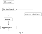
- control unit is configured to trigger image taking after a section.
- This can be preferably used for taking multiple images in a row, e.g. in order to perform a 3D reconstruction function as shown in FIG. 3 .
- This is a function to reconstruct 3D model of specimen.
- control unit controls the microtome (especially the electric motors and the clutch) to cut specimen for one section, then moves the slide into an image taking position, especially the memory position mentioned above, then stops and sends a relay signal to an external camera.
- the camera gets the relay signal and takes a picture, then sends a feedback relay signal to microtome to trigger the second section.
- control unit of a microtome can control up and down movement of the slide as well as forwards and backwards movement of the slide, can move the slide with the specimen into the memory position and can and trigger the image acquisition.
Landscapes
- Physics & Mathematics (AREA)
- Health & Medical Sciences (AREA)
- Life Sciences & Earth Sciences (AREA)
- Chemical & Material Sciences (AREA)
- Analytical Chemistry (AREA)
- Biochemistry (AREA)
- General Health & Medical Sciences (AREA)
- General Physics & Mathematics (AREA)
- Immunology (AREA)
- Pathology (AREA)
- Sampling And Sample Adjustment (AREA)
Claims (12)
- Microtome (1) comportant :un couteau de coupe (4),un porte-objet (6) monté sur un coulisseau (5), le coulisseau (5) étant mobile par rapport au couteau de coupe (4) dans une direction de coupe et dans une direction de définition d'épaisseur,un mouvement du coulisseau (5) dans la direction de définition d'épaisseur étant effectué par un premier moteur électrique commandé par une unité de commande,un mouvement du coulisseau (5) dans la direction de coupe étant effectué par un second moteur électrique commandé par l'unité de commande,l'unité de commande étant configurée pour commander le mouvement du coulisseau dans la direction de définition d'épaisseur et dans la direction de coupe,l'unité de commande étant configurée pour fournir une position de mémoire et pour déplacer le coulisseau (5) qui se trouve dans la direction de définition d'épaisseur vers la position de mémoire en réaction à un ordre correspondant,la position de mémoire étant une position horizontale à l'écart du couteau de coupe (4),l'unité de commande étant configurée pour déclencher une prise d'image après une section lorsque le coulisseau (5) est dans la position de mémoire.
- Microtome (1) selon la revendication 1, le microtome comprenant un premier volant (14), et le coulisseau (5) étant déplacé dans la direction de définition d'épaisseur en fonction de la rotation du premier volant (14).
- Microtome (1) selon la revendication 2, le microtome comprenant une chaîne cinématique électrique comprenant un codeur pour surveiller la rotation du premier volant (14), et le premier volant (14) étant accouplé au coulisseau (5) par l'intermédiaire de la chaîne cinématique électrique et du premier moteur électrique pour déplacer le coulisseau (5) dans la direction de définition d'épaisseur en fonction de la rotation du premier volant (14).
- Microtome (1) selon l'une quelconque des revendications précédentes, dans lequel l'unité de commande est configurée pour stocker et/ou effacer la position de mémoire en réaction à un ordre correspondant.
- Microtome (1) selon l'une quelconque des revendications précédentes, dans lequel l'unité de commande est configurée pour commander le premier moteur électrique pour qu'il tourne à au moins trois vitesses différentes.
- Microtome (1) selon l'une quelconque des revendications précédentes, dans lequel le coulisseau (5) est déplacé dans la direction de coupe en fonction de la rotation d'un second volant (8).
- Microtome (1) selon la revendication 6, dans lequel le second volant (8) est accouplé au coulisseau (5) par l'intermédiaire d'une chaîne cinématique mécanique.
- Microtome (1) selon l'une quelconque des revendications précédentes, dans lequel le coulisseau (5) est déplacé dans la direction de coupe par le second moteur électrique commandé par l'unité de commande.
- Microtome (1) selon la revendication 8, le microtome comprenant un embrayage actionnable électriquement entre le second moteur électrique et le coulisseau (5), l'embrayage étant commandé par l'unité de commande.
- Microtome (1) selon la revendication 11, dans lequel l'unité de commande est configurée pour ouvrir et/ou fermer l'embrayage en réaction à un ordre de freinage.
- Microtome selon l'une quelconque des revendications précédentes, le microtome comprenant un panneau de commande externe (10) et l'unité de commande étant connectée au panneau de commande externe (10), et le panneau de commande (10) comportant un clavier (11) configuré pour des entrées numériques, un dispositif de commande rotatif (13) configuré pour des entrées à variation continue, et des commutateurs (12) configurés pour l'entrée de positions de commutateur et d'états de fonctionnement spécifiques.
- Microtome selon l'une quelconque des revendications précédentes, dans lequel le premier moteur électrique et/ou le second moteur électrique sont configurés comme un moteur pas à pas ou comme un moteur à courant continu, notamment un moteur à courant continu sans balais.
Applications Claiming Priority (1)
| Application Number | Priority Date | Filing Date | Title |
|---|---|---|---|
| PCT/CN2017/113802 WO2019104585A1 (fr) | 2017-11-30 | 2017-11-30 | Commande de microtome motorisé |
Publications (3)
| Publication Number | Publication Date |
|---|---|
| EP3631405A1 EP3631405A1 (fr) | 2020-04-08 |
| EP3631405A4 EP3631405A4 (fr) | 2020-12-30 |
| EP3631405B1 true EP3631405B1 (fr) | 2024-11-06 |
Family
ID=66663752
Family Applications (1)
| Application Number | Title | Priority Date | Filing Date |
|---|---|---|---|
| EP17933419.8A Active EP3631405B1 (fr) | 2017-11-30 | 2017-11-30 | Commande de microtome motorisé |
Country Status (5)
| Country | Link |
|---|---|
| US (1) | US11333582B2 (fr) |
| EP (1) | EP3631405B1 (fr) |
| JP (1) | JP7334153B2 (fr) |
| CN (1) | CN111417847A (fr) |
| WO (1) | WO2019104585A1 (fr) |
Families Citing this family (4)
| Publication number | Priority date | Publication date | Assignee | Title |
|---|---|---|---|---|
| CN109656155B (zh) * | 2017-10-11 | 2023-05-12 | 徕卡显微系统(上海)有限公司 | 石蜡切片机及其控制方法 |
| WO2021119672A1 (fr) * | 2019-12-10 | 2021-06-17 | Hobbs Boyd Randolph | Volants et consoles de commande associées |
| MX2020007709A (es) * | 2020-07-20 | 2022-01-21 | Jesus Raul Beltran Ramirez | Aparato portatil para corte automatico de muestras hitologicas. |
| CN115446883A (zh) * | 2022-09-27 | 2022-12-09 | 广州秀威科技有限公司 | 可自由调节手轮力度的切片机 |
Citations (3)
| Publication number | Priority date | Publication date | Assignee | Title |
|---|---|---|---|---|
| JPH05256745A (ja) * | 1992-03-16 | 1993-10-05 | Feather Safety Razor Co Ltd | ミクロトーム |
| US5906148A (en) * | 1997-01-10 | 1999-05-25 | Chuo Precision Industrial Co., Ltd. | Microtome having vibration dampening and micro-feeding mechanism |
| US20100050839A1 (en) * | 2008-08-29 | 2010-03-04 | Tatsuya Miyatani | Thin-section manufacturing apparatus |
Family Cites Families (25)
| Publication number | Priority date | Publication date | Assignee | Title |
|---|---|---|---|---|
| US3884563A (en) | 1971-04-07 | 1975-05-20 | Fox John C | Microtome with rotating knife |
| US3926085A (en) * | 1974-12-02 | 1975-12-16 | American Optical Corp | Specimen feed for a microtome |
| DE3404098C1 (de) * | 1984-02-07 | 1990-02-15 | Parke, Davis & Co., Morris Plains, N.J. | Mikrotom mit einer Objektrueckzugeinrichtung |
| DE3830725A1 (de) | 1988-09-09 | 1990-03-22 | Leitz Wild Gmbh | Automatische arretierung der antriebseinrichtung eines mikrotoms |
| JP3588174B2 (ja) * | 1995-11-16 | 2004-11-10 | 財団法人神奈川科学技術アカデミー | 固形試料構造検査方法及びそのための装置 |
| DE29723697U1 (de) * | 1996-01-16 | 1999-02-04 | Dern, Klaus, Ellijay, Ga | Rotationsmikrotom mit horizontalem Vorschub |
| EP0920613B1 (fr) | 1996-07-29 | 2002-10-02 | Leica Microsystems Nussloch GmbH | Microtome a disque |
| JP2000134867A (ja) | 1998-10-20 | 2000-05-12 | Higashifuji Manuf Ltd | クラッチ付きモータ |
| DE19911173C2 (de) * | 1999-03-12 | 2002-01-31 | Leica Microsystems | Mikrotom mit einem motorischen Zustellantrieb |
| DE19911163C1 (de) * | 1999-03-12 | 2000-07-20 | Leica Microsystems | Mikrotom |
| DE10106033A1 (de) * | 2001-02-09 | 2002-08-29 | Hess Consult Gmbh | Mikrotom |
| DE102004001475B4 (de) | 2004-01-08 | 2006-02-02 | Leica Mikrosysteme Gmbh | Verfahren zum Trimmen von Proben |
| DE102005042367B4 (de) | 2005-09-07 | 2009-11-12 | Leica Microsystems Cms Gmbh | Vorrichtung zum Erzeugen von 3-D Bildern einer Probe |
| DE102007026844B4 (de) * | 2007-06-06 | 2011-02-17 | Leica Biosystems Nussloch Gmbh | Vorrichtung zum Bremsen der Welle eines Mikrotoms |
| CN201069415Y (zh) * | 2007-06-15 | 2008-06-04 | 浙江省金华市科迪仪器有限公司 | 一种生物组织切片机 |
| DE102008016165B4 (de) * | 2008-03-28 | 2010-10-14 | Leica Biosystems Nussloch Gmbh | Mikrotom mit variablem Schneidehub unter Verwendung eines Linearmotors als Antrieb |
| US9032854B2 (en) * | 2011-12-21 | 2015-05-19 | Sakura Finetek U.S.A., Inc. | Reciprocating microtome drive system |
| DE102012106845B4 (de) * | 2012-07-27 | 2014-08-07 | Leica Biosystems Nussloch Gmbh | Mikrotom mit Auto-Rocking-Modus |
| DE102013110776B4 (de) * | 2013-09-30 | 2015-05-13 | Leica Biosystems Nussloch Gmbh | Verfahren und Mikrotom zum Herstellen von Dünnschnitten mit einem Schnittprofilaufzeichnungsmodus |
| US20150138532A1 (en) * | 2013-10-31 | 2015-05-21 | 3Scan Inc. | Motion strategies for scanning microscope imaging |
| US10571368B2 (en) * | 2015-06-30 | 2020-02-25 | Clarapath, Inc. | Automated system and method for advancing tape to transport cut tissue sections |
| CN205280408U (zh) * | 2015-12-21 | 2016-06-01 | 浙江省金华市科迪仪器设备有限公司 | 生物组织切片机 |
| US10724929B2 (en) * | 2016-05-13 | 2020-07-28 | Clarapath, Inc. | Automated tissue sectioning and storage system |
| US10422724B2 (en) * | 2016-11-14 | 2019-09-24 | Sakura Finetek U.S.A., Inc. | Microtome waste removal assembly |
| CN106815886A (zh) * | 2016-12-30 | 2017-06-09 | 山东大学 | 一种生物标本断层切割成像设备及其工作方法 |
-
2017
- 2017-11-30 JP JP2020528025A patent/JP7334153B2/ja active Active
- 2017-11-30 US US16/626,895 patent/US11333582B2/en active Active
- 2017-11-30 WO PCT/CN2017/113802 patent/WO2019104585A1/fr not_active Ceased
- 2017-11-30 CN CN201780097331.3A patent/CN111417847A/zh active Pending
- 2017-11-30 EP EP17933419.8A patent/EP3631405B1/fr active Active
Patent Citations (3)
| Publication number | Priority date | Publication date | Assignee | Title |
|---|---|---|---|---|
| JPH05256745A (ja) * | 1992-03-16 | 1993-10-05 | Feather Safety Razor Co Ltd | ミクロトーム |
| US5906148A (en) * | 1997-01-10 | 1999-05-25 | Chuo Precision Industrial Co., Ltd. | Microtome having vibration dampening and micro-feeding mechanism |
| US20100050839A1 (en) * | 2008-08-29 | 2010-03-04 | Tatsuya Miyatani | Thin-section manufacturing apparatus |
Also Published As
| Publication number | Publication date |
|---|---|
| EP3631405A4 (fr) | 2020-12-30 |
| EP3631405A1 (fr) | 2020-04-08 |
| CN111417847A (zh) | 2020-07-14 |
| WO2019104585A1 (fr) | 2019-06-06 |
| JP7334153B2 (ja) | 2023-08-28 |
| US11333582B2 (en) | 2022-05-17 |
| JP2021509948A (ja) | 2021-04-08 |
| US20200124502A1 (en) | 2020-04-23 |
Similar Documents
| Publication | Publication Date | Title |
|---|---|---|
| EP3370055B1 (fr) | Système d'entraînement de microtome à va-et-vient | |
| EP3631405B1 (fr) | Commande de microtome motorisé | |
| US8967026B2 (en) | Microtome having an auto-rocking mode | |
| US9541473B2 (en) | Microtome having a piezoelectric linear actuator | |
| US20090241751A1 (en) | Microtome having a variable sectioning stroke, using a linear motor as a drive system | |
| US10345198B2 (en) | Method and microtome for producing thin sections with a section profile recording mode | |
| JP2000515973A (ja) | ディスク形ミクロトーム | |
| JPH10504103A (ja) | ミクロトーム | |
| CN109732673A (zh) | 一种切片机 | |
| US11467068B2 (en) | Microtome and method for positioning a microtome specimen head | |
| JP2589394B2 (ja) | ミクロトーム | |
| CN115326451A (zh) | 一种全自动的病理组织蜡块切片机 | |
| CN115070847A (zh) | 组织自动切片速度分段控制装置和控制方法 |
Legal Events
| Date | Code | Title | Description |
|---|---|---|---|
| STAA | Information on the status of an ep patent application or granted ep patent |
Free format text: STATUS: THE INTERNATIONAL PUBLICATION HAS BEEN MADE |
|
| PUAI | Public reference made under article 153(3) epc to a published international application that has entered the european phase |
Free format text: ORIGINAL CODE: 0009012 |
|
| STAA | Information on the status of an ep patent application or granted ep patent |
Free format text: STATUS: REQUEST FOR EXAMINATION WAS MADE |
|
| 17P | Request for examination filed |
Effective date: 20191230 |
|
| AK | Designated contracting states |
Kind code of ref document: A1 Designated state(s): AL AT BE BG CH CY CZ DE DK EE ES FI FR GB GR HR HU IE IS IT LI LT LU LV MC MK MT NL NO PL PT RO RS SE SI SK SM TR |
|
| AX | Request for extension of the european patent |
Extension state: BA ME |
|
| A4 | Supplementary search report drawn up and despatched |
Effective date: 20201127 |
|
| RIC1 | Information provided on ipc code assigned before grant |
Ipc: G01N 1/06 20060101AFI20201123BHEP |
|
| DAV | Request for validation of the european patent (deleted) | ||
| DAX | Request for extension of the european patent (deleted) | ||
| STAA | Information on the status of an ep patent application or granted ep patent |
Free format text: STATUS: EXAMINATION IS IN PROGRESS |
|
| 17Q | First examination report despatched |
Effective date: 20220901 |
|
| GRAP | Despatch of communication of intention to grant a patent |
Free format text: ORIGINAL CODE: EPIDOSNIGR1 |
|
| STAA | Information on the status of an ep patent application or granted ep patent |
Free format text: STATUS: GRANT OF PATENT IS INTENDED |
|
| INTG | Intention to grant announced |
Effective date: 20240612 |
|
| GRAS | Grant fee paid |
Free format text: ORIGINAL CODE: EPIDOSNIGR3 |
|
| GRAA | (expected) grant |
Free format text: ORIGINAL CODE: 0009210 |
|
| STAA | Information on the status of an ep patent application or granted ep patent |
Free format text: STATUS: THE PATENT HAS BEEN GRANTED |
|
| AK | Designated contracting states |
Kind code of ref document: B1 Designated state(s): AL AT BE BG CH CY CZ DE DK EE ES FI FR GB GR HR HU IE IS IT LI LT LU LV MC MK MT NL NO PL PT RO RS SE SI SK SM TR |
|
| REG | Reference to a national code |
Ref country code: GB Ref legal event code: FG4D |
|
| REG | Reference to a national code |
Ref country code: CH Ref legal event code: EP |
|
| REG | Reference to a national code |
Ref country code: DE Ref legal event code: R096 Ref document number: 602017086034 Country of ref document: DE |
|
| REG | Reference to a national code |
Ref country code: IE Ref legal event code: FG4D |
|
| P01 | Opt-out of the competence of the unified patent court (upc) registered |
Free format text: CASE NUMBER: APP_63955/2024 Effective date: 20241203 |
|
| REG | Reference to a national code |
Ref country code: LT Ref legal event code: MG9D |
|
| REG | Reference to a national code |
Ref country code: NL Ref legal event code: MP Effective date: 20241106 |
|
| PG25 | Lapsed in a contracting state [announced via postgrant information from national office to epo] |
Ref country code: PT Free format text: LAPSE BECAUSE OF FAILURE TO SUBMIT A TRANSLATION OF THE DESCRIPTION OR TO PAY THE FEE WITHIN THE PRESCRIBED TIME-LIMIT Effective date: 20250306 Ref country code: IS Free format text: LAPSE BECAUSE OF FAILURE TO SUBMIT A TRANSLATION OF THE DESCRIPTION OR TO PAY THE FEE WITHIN THE PRESCRIBED TIME-LIMIT Effective date: 20250306 Ref country code: HR Free format text: LAPSE BECAUSE OF FAILURE TO SUBMIT A TRANSLATION OF THE DESCRIPTION OR TO PAY THE FEE WITHIN THE PRESCRIBED TIME-LIMIT Effective date: 20241106 |
|
| PG25 | Lapsed in a contracting state [announced via postgrant information from national office to epo] |
Ref country code: FI Free format text: LAPSE BECAUSE OF FAILURE TO SUBMIT A TRANSLATION OF THE DESCRIPTION OR TO PAY THE FEE WITHIN THE PRESCRIBED TIME-LIMIT Effective date: 20241106 Ref country code: NL Free format text: LAPSE BECAUSE OF FAILURE TO SUBMIT A TRANSLATION OF THE DESCRIPTION OR TO PAY THE FEE WITHIN THE PRESCRIBED TIME-LIMIT Effective date: 20241106 |
|
| REG | Reference to a national code |
Ref country code: AT Ref legal event code: MK05 Ref document number: 1739829 Country of ref document: AT Kind code of ref document: T Effective date: 20241106 |
|
| PG25 | Lapsed in a contracting state [announced via postgrant information from national office to epo] |
Ref country code: BG Free format text: LAPSE BECAUSE OF FAILURE TO SUBMIT A TRANSLATION OF THE DESCRIPTION OR TO PAY THE FEE WITHIN THE PRESCRIBED TIME-LIMIT Effective date: 20241106 |
|
| PG25 | Lapsed in a contracting state [announced via postgrant information from national office to epo] |
Ref country code: ES Free format text: LAPSE BECAUSE OF FAILURE TO SUBMIT A TRANSLATION OF THE DESCRIPTION OR TO PAY THE FEE WITHIN THE PRESCRIBED TIME-LIMIT Effective date: 20241106 |
|
| PG25 | Lapsed in a contracting state [announced via postgrant information from national office to epo] |
Ref country code: NO Free format text: LAPSE BECAUSE OF FAILURE TO SUBMIT A TRANSLATION OF THE DESCRIPTION OR TO PAY THE FEE WITHIN THE PRESCRIBED TIME-LIMIT Effective date: 20250206 |
|
| PG25 | Lapsed in a contracting state [announced via postgrant information from national office to epo] |
Ref country code: GR Free format text: LAPSE BECAUSE OF FAILURE TO SUBMIT A TRANSLATION OF THE DESCRIPTION OR TO PAY THE FEE WITHIN THE PRESCRIBED TIME-LIMIT Effective date: 20250207 Ref country code: LV Free format text: LAPSE BECAUSE OF FAILURE TO SUBMIT A TRANSLATION OF THE DESCRIPTION OR TO PAY THE FEE WITHIN THE PRESCRIBED TIME-LIMIT Effective date: 20241106 Ref country code: AT Free format text: LAPSE BECAUSE OF FAILURE TO SUBMIT A TRANSLATION OF THE DESCRIPTION OR TO PAY THE FEE WITHIN THE PRESCRIBED TIME-LIMIT Effective date: 20241106 |
|
| PG25 | Lapsed in a contracting state [announced via postgrant information from national office to epo] |
Ref country code: PL Free format text: LAPSE BECAUSE OF FAILURE TO SUBMIT A TRANSLATION OF THE DESCRIPTION OR TO PAY THE FEE WITHIN THE PRESCRIBED TIME-LIMIT Effective date: 20241106 |
|
| PG25 | Lapsed in a contracting state [announced via postgrant information from national office to epo] |
Ref country code: RS Free format text: LAPSE BECAUSE OF FAILURE TO SUBMIT A TRANSLATION OF THE DESCRIPTION OR TO PAY THE FEE WITHIN THE PRESCRIBED TIME-LIMIT Effective date: 20250206 |
|
| REG | Reference to a national code |
Ref country code: CH Ref legal event code: PL |
|
| PG25 | Lapsed in a contracting state [announced via postgrant information from national office to epo] |
Ref country code: SM Free format text: LAPSE BECAUSE OF FAILURE TO SUBMIT A TRANSLATION OF THE DESCRIPTION OR TO PAY THE FEE WITHIN THE PRESCRIBED TIME-LIMIT Effective date: 20241106 |
|
| PG25 | Lapsed in a contracting state [announced via postgrant information from national office to epo] |
Ref country code: DK Free format text: LAPSE BECAUSE OF FAILURE TO SUBMIT A TRANSLATION OF THE DESCRIPTION OR TO PAY THE FEE WITHIN THE PRESCRIBED TIME-LIMIT Effective date: 20241106 |
|
| PG25 | Lapsed in a contracting state [announced via postgrant information from national office to epo] |
Ref country code: LU Free format text: LAPSE BECAUSE OF NON-PAYMENT OF DUE FEES Effective date: 20241130 |
|
| REG | Reference to a national code |
Ref country code: CH Ref legal event code: PL |
|
| PG25 | Lapsed in a contracting state [announced via postgrant information from national office to epo] |
Ref country code: EE Free format text: LAPSE BECAUSE OF FAILURE TO SUBMIT A TRANSLATION OF THE DESCRIPTION OR TO PAY THE FEE WITHIN THE PRESCRIBED TIME-LIMIT Effective date: 20241106 |
|
| PG25 | Lapsed in a contracting state [announced via postgrant information from national office to epo] |
Ref country code: CH Free format text: LAPSE BECAUSE OF NON-PAYMENT OF DUE FEES Effective date: 20241130 |
|
| PG25 | Lapsed in a contracting state [announced via postgrant information from national office to epo] |
Ref country code: RO Free format text: LAPSE BECAUSE OF FAILURE TO SUBMIT A TRANSLATION OF THE DESCRIPTION OR TO PAY THE FEE WITHIN THE PRESCRIBED TIME-LIMIT Effective date: 20241106 |
|
| PG25 | Lapsed in a contracting state [announced via postgrant information from national office to epo] |
Ref country code: SK Free format text: LAPSE BECAUSE OF FAILURE TO SUBMIT A TRANSLATION OF THE DESCRIPTION OR TO PAY THE FEE WITHIN THE PRESCRIBED TIME-LIMIT Effective date: 20241106 |
|
| PG25 | Lapsed in a contracting state [announced via postgrant information from national office to epo] |
Ref country code: CZ Free format text: LAPSE BECAUSE OF FAILURE TO SUBMIT A TRANSLATION OF THE DESCRIPTION OR TO PAY THE FEE WITHIN THE PRESCRIBED TIME-LIMIT Effective date: 20241106 |
|
| REG | Reference to a national code |
Ref country code: DE Ref legal event code: R097 Ref document number: 602017086034 Country of ref document: DE |
|
| REG | Reference to a national code |
Ref country code: BE Ref legal event code: MM Effective date: 20241130 |
|
| PG25 | Lapsed in a contracting state [announced via postgrant information from national office to epo] |
Ref country code: SE Free format text: LAPSE BECAUSE OF FAILURE TO SUBMIT A TRANSLATION OF THE DESCRIPTION OR TO PAY THE FEE WITHIN THE PRESCRIBED TIME-LIMIT Effective date: 20241106 |
|
| PLBE | No opposition filed within time limit |
Free format text: ORIGINAL CODE: 0009261 |
|
| STAA | Information on the status of an ep patent application or granted ep patent |
Free format text: STATUS: NO OPPOSITION FILED WITHIN TIME LIMIT |
|
| PG25 | Lapsed in a contracting state [announced via postgrant information from national office to epo] |
Ref country code: MC Free format text: LAPSE BECAUSE OF FAILURE TO SUBMIT A TRANSLATION OF THE DESCRIPTION OR TO PAY THE FEE WITHIN THE PRESCRIBED TIME-LIMIT Effective date: 20241106 |
|
| 26N | No opposition filed |
Effective date: 20250807 |
|
| PG25 | Lapsed in a contracting state [announced via postgrant information from national office to epo] |
Ref country code: BE Free format text: LAPSE BECAUSE OF NON-PAYMENT OF DUE FEES Effective date: 20241130 |
|
| PG25 | Lapsed in a contracting state [announced via postgrant information from national office to epo] |
Ref country code: IE Free format text: LAPSE BECAUSE OF NON-PAYMENT OF DUE FEES Effective date: 20241130 |
|
| PGFP | Annual fee paid to national office [announced via postgrant information from national office to epo] |
Ref country code: DE Payment date: 20251126 Year of fee payment: 9 |
|
| PGFP | Annual fee paid to national office [announced via postgrant information from national office to epo] |
Ref country code: GB Payment date: 20251125 Year of fee payment: 9 |
|
| PGFP | Annual fee paid to national office [announced via postgrant information from national office to epo] |
Ref country code: IT Payment date: 20251121 Year of fee payment: 9 |
|
| PGFP | Annual fee paid to national office [announced via postgrant information from national office to epo] |
Ref country code: FR Payment date: 20251125 Year of fee payment: 9 |
|
| PG25 | Lapsed in a contracting state [announced via postgrant information from national office to epo] |
Ref country code: CY Free format text: LAPSE BECAUSE OF FAILURE TO SUBMIT A TRANSLATION OF THE DESCRIPTION OR TO PAY THE FEE WITHIN THE PRESCRIBED TIME-LIMIT; INVALID AB INITIO Effective date: 20171130 |