EP3631424B1 - Vorrichtung zur detektion eines defekts auf einer oberfläche unter verwendung von multidirektionaler beleuchtung - Google Patents
Vorrichtung zur detektion eines defekts auf einer oberfläche unter verwendung von multidirektionaler beleuchtung Download PDFInfo
- Publication number
- EP3631424B1 EP3631424B1 EP18724589.9A EP18724589A EP3631424B1 EP 3631424 B1 EP3631424 B1 EP 3631424B1 EP 18724589 A EP18724589 A EP 18724589A EP 3631424 B1 EP3631424 B1 EP 3631424B1
- Authority
- EP
- European Patent Office
- Prior art keywords
- optical
- lighting
- detection device
- defect
- point
- Prior art date
- Legal status (The legal status is an assumption and is not a legal conclusion. Google has not performed a legal analysis and makes no representation as to the accuracy of the status listed.)
- Active
Links
Images


Classifications
-
- G—PHYSICS
- G01—MEASURING; TESTING
- G01N—INVESTIGATING OR ANALYSING MATERIALS BY DETERMINING THEIR CHEMICAL OR PHYSICAL PROPERTIES
- G01N21/00—Investigating or analysing materials by the use of optical means, i.e. using sub-millimetre waves, infrared, visible or ultraviolet light
- G01N21/84—Systems specially adapted for particular applications
- G01N21/88—Investigating the presence of flaws or contamination
- G01N21/8806—Specially adapted optical and illumination features
-
- G—PHYSICS
- G01—MEASURING; TESTING
- G01N—INVESTIGATING OR ANALYSING MATERIALS BY DETERMINING THEIR CHEMICAL OR PHYSICAL PROPERTIES
- G01N21/00—Investigating or analysing materials by the use of optical means, i.e. using sub-millimetre waves, infrared, visible or ultraviolet light
- G01N21/17—Systems in which incident light is modified in accordance with the properties of the material investigated
- G01N21/47—Scattering, i.e. diffuse reflection
- G01N21/4738—Diffuse reflection, e.g. also for testing fluids, fibrous materials
- G01N21/474—Details of optical heads therefor, e.g. using optical fibres
-
- G—PHYSICS
- G01—MEASURING; TESTING
- G01N—INVESTIGATING OR ANALYSING MATERIALS BY DETERMINING THEIR CHEMICAL OR PHYSICAL PROPERTIES
- G01N21/00—Investigating or analysing materials by the use of optical means, i.e. using sub-millimetre waves, infrared, visible or ultraviolet light
- G01N21/84—Systems specially adapted for particular applications
- G01N21/88—Investigating the presence of flaws or contamination
- G01N21/95—Investigating the presence of flaws or contamination characterised by the material or shape of the object to be examined
- G01N21/956—Inspecting patterns on the surface of objects
- G01N21/95684—Patterns showing highly reflecting parts, e.g. metallic elements
Definitions
- the present invention relates to a device for detecting a defect on a surface.
- a current device consists essentially of an optical device capable of acquiring an image or film of the surface. This image or film is then viewed by an operator who indicates the defects he has spotted.
- the operator may not spot a defect due to lack of attention.
- the criteria for judging a defect are subjective, i.e. the definition of what is a defect may vary depending on the operator.
- a solution that is often implemented to overcome these problems is the viewing of the film or image by several operators.
- surface image examples are used to show what is a defect or not.
- JP 2012 047673 A describes a system for inspecting a surface.
- Its illumination unit comprises several light sources and a hood on which the light sources are arranged.
- the hood consists of a hemispherical element that covers the object being inspected.
- An illumination control unit sequentially switches on the light sources in a predetermined order.
- the imaging control unit causes the image sensor to capture an image in synchronization with the moment when the illumination control unit switches on a light source. Thus, if the number of an image is known, it is possible to identify the illumination direction of the object being inspected.
- WO 02/090952 A1 describes a method of examining a surface in which light which successively strikes the surface at different angles of incidence and which is reflected on said surface is measured by an image sensor.
- the invention aims in particular to remedy this drawback by providing a device allowing simple and reliable detection of a defect on a surface.
- the invention relates in particular to a device for detecting a defect on a surface according to claim 1.
- the detection device according to the invention may further comprise characteristics according to claims 2 to 10.
- FIG. 1 And 2 An example of a device 10 for detecting a defect in a surface 12 is shown in figures 1 And 2 .
- the detection device 10 comprises an optical device 14, a lighting device 15 comprising a first number of light source(s) 16 and an electronic calculation device 18.
- the optical device 14 has an optical axis aligned with a given optical direction O. It has an acquisition field.
- the optical device 14 is capable of acquiring an image of the surface 12 according to the given optical direction O.
- the acquisition field coincides with the surface 12 to be inspected, so that the acquired image represents the surface 12.
- the optical device comprises, for example, at the input an optic adapting the image acquired by the optical device, for example, the acquisition field.
- the acquisition field is fixed here.
- the optical direction O is typically substantially perpendicular to the surface 12. Alternatively, the optical direction O is not perpendicular to the surface 12.
- the optical device 14 is, for example, a camera.
- the optical device 14 is, more particularly, a charge-coupled device, more commonly called a CCD sensor from the English “ charge-couple device ”, or a CMOS sensor from the English “ complementary metal oxide semi-conductor ” .
- the acquisition field coincides only with a portion of the surface 12 and the detection device 10 is capable of being moved relative to the surface 12 so as to be able to acquire the entire surface 12 in several portions.
- Each acquired image consists of a matrix of pixels of dimension i*j, with i the number of horizontal lines and j the number of vertical lines of the matrix, with at least one of the two parameters (i,j) greater than 1.
- the pixel is, for example, a rectangle of size noted h*L, with h its height and L its width.
- the height h is equal to the width L. Alternatively, the height is different from the width
- the light sources 16 are capable of illuminating the surface 12.
- the light sources 16 each have a given lighting direction E, E' connecting the light source to the point on the surface 12.
- the lighting direction is different for each light source.
- the light sources 16 are typically arranged in a half-sphere 20 surrounding the surface 12.
- the hemisphere has a diameter D less than or equal to 50 mm (millimeters), preferably less than or equal to 20 mm.
- the diameter D is, moreover, strictly greater than 5 mm.
- the first number of light sources 16 is between 32 and 128, more particularly equal to 96.
- the light sources 16 are, for example, light-emitting diodes (LEDs).
- They can be turned off or on. They are configured so that they can be turned on independently of each other.
- the 16 light sources have identical light intensity.
- the lighting device 15 comprises one or more possibly non-identical lights.
- the electronic calculation device 18 is, for example, a computer, a calculator, a calculation module, at least one programmable logic component such as FPGAs ( Field-Programmable Gate Arrays ) or at least one dedicated integrated circuit such as ASICs ( Application-Specific Integrated Circuits ) .
- programmable logic component such as FPGAs ( Field-Programmable Gate Arrays ) or at least one dedicated integrated circuit such as ASICs ( Application-Specific Integrated Circuits ) .
- the electronic computing device 18 is, for example, connected to the optical device 14 and to the lighting device 15.
- connection is, for example, made by cables.
- connection between the electronic computing device 18 and the optical device 14 and/or the lighting device 15 is made by wireless technology.
- the wireless technology is, for example, according to a Wifi protocol corresponding to a set of wireless communication protocols governed by the standards of the IEEE 802.11 group (ISO/IEC 8802-11).
- the electronic calculation device 18 is capable of switching on or off each of the light sources 16 independently of each other.
- the electronic calculation device 18 is further provided to trigger the acquisition of at least one image of the surface by the optical device 14.
- each image being acquired according to the given optical direction O and with a single light source turned on or a defined combination of single sources turned on. This source or combination is different for each image. Each image corresponds to different lighting.
- the electronic calculation device 18 is configured to calculate from the acquired images a plurality of parameters, the parameters comprising coefficients of an equation characterizing the response of said point of the surface as a function of the lighting direction and an observation direction, then to deduce from the calculated parameters if the surface has a defect at said point.
- the device 10 here comprises a tool 22 comprising the optical device 14 and the lighting device 15.
- the electronic calculation device 18 is placed outside the tool 22.
- the electronic computing device 18 is, for example, placed on a movable support 23.
- the support 23 comprises, for example, rollers.
- the tool 22 has dimensions such that it is included in a cylinder having a length equal to 200 mm, more particularly equal to 150 mm, and a diameter equal to 100 mm, more particularly equal to 75 mm.
- Tool 22 has a mass of less than 3 kg (kilograms), more specifically less than 2 kg.
- the tool comprises a handle 24 and a head 26 secured to each other.
- the tool 22 is, for example, made up of the handle 24 and the head 26.
- the handle 24 and the head 26 are immobile relative to each other.
- they are made of one material.
- the handle 24 and the head 26 are integral in a connection zone, the handle 24 being able to be moved relative to the head 26 according to a pivot connection or a ball joint connection.
- the handle 24 is capable of being grasped by a user.
- the handle 24 is substantially cylindrical.
- the head 26 here comprises the optical device 14 and the lighting device 15.
- the head 26 defines a concavity 28.
- the concavity 28 is open, that is to say it communicates with the exterior of the tool 22.
- the concavity 28 is open opposite the handle 24.
- the concavity defines an internal shape corresponding to the half-sphere 20 of the lighting device 15.
- the head 26 is connected to the handle 24 at a point aligned in the longitudinal direction of the handle 24 with the top of the half-sphere 20. More particularly, the handle 24 is aligned in its longitudinal direction with the top of the half-sphere 20.
- the light sources 16 are capable of illuminating the concavity 28.
- the optical device 14 is placed at the top of the half-sphere 20.
- the optical axis of the optical device 14 extends into the concavity 28.
- the head 26 is capable of being applied in contact with the surface 12. More particularly, it comprises a support surface 30 capable of being placed in contact with the surface 12, so that the surface 12 is capable of being illuminated with the lighting device 15 and acquired with the optical device 14.
- the bearing surface 30 is adapted so that the concavity 28 of the head 26 forms a closed space when the bearing surface 30 is placed in contact with the surface 12.
- the bearing surface 30 extends around a circle defining an edge of the concavity 28.
- the support surface 30 is included in a plane substantially perpendicular to the optical direction O of the optical device 14.
- the support surface 30 is a ring whose internal radius corresponds to a radius of the half-sphere 20 of the lighting device 15.
- the tool 22 further comprises at least one adapter piece having a generally cylindrical shape extending between a first and a second end surface.
- the first end surface is adapted to cooperate with the support surface 30.
- the second end surface is adapted to cooperate with the surface 12 on which the tool is intended to be applied.
- the second end surface is a ring having a curvature similar to the surface.
- the adapter piece is, for example, opaque, so that the light is maintained in the space defined between the light sources 16, the surface 12 and the adapter piece.
- the electronic calculation device 18 is included in the tool 22, more particularly in the handle 24.
- the method is implemented here by the device described above.
- the device 10 is placed in contact with the surface 12, more particularly at the level of the support surface 30 of the device 10.
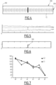
- a plurality of images 200 of the surface are acquired by the optical device 14. Such an image is represented at figure 3 .
- Each image 200 is acquired with illumination of the surface 12 according to a given illumination direction E, E' for each point of the surface and with the optical axis of the optical device 14 according to a given optical direction O.
- the 200 images are acquired with different lighting directions E, E' or combinations of lighting directions.
- the lighting directions E, E' differ for each acquired image and the optical direction O is invariable and substantially perpendicular to the surface 12.
- a single light source or a defined combination of single sources 16 of the illumination device is illuminated, the single light source or combination being different for each acquired image.
- All of the light sources or combinations are turned on in turn, so as to acquire one image per light source or combination. Alternatively, some sources or combinations are not turned on.
- the parameters are calculated from the coefficients of an equation characterizing the response of said point on the surface as a function of the lighting direction E, E' and an observation direction B, B'.
- the magnitude here is the gray intensity of the surface point, the gray intensity being variable according to the acquired images.
- a model representing the evolution of the quantity is chosen 108.
- the model depends on the lighting direction(s) E, E' and/or the observation direction B, B'.
- the model includes coefficients.
- G ( E ) a 0 ⁇ D u 2 + a 1 ⁇ D v 2 + a 2 ⁇ D u ⁇ D v + a 3 ⁇ D u + a 4 ⁇ D v + a 5
- G the magnitude, E the lighting direction, a 0 , a 1 , a 2 , a 3 , a 4 and a 5
- the coefficients and D u and D v being coordinates of the vector connecting the lighting source to the point on the surface.
- the coefficients a 0 , a 1 , a 2 , a 3 , a 4 and a 5 are here undetermined.
- the parameters are here equal to the coefficients a 0 , a 1 , a 2 , a 3 , a 4 and a 5 thus calculated.
- the parameters are other values calculated from the coefficients.
- the parameters are represented with the curve C 1 at a point not presenting a defect and with the curve C 2 at a point presenting a defect.
- the result obtained in step 104 for each point is, for example, a boolean representing binary whether a fault is detected at said point.
- the boolean is represented along line 204: if the boolean is equal to 0, no fault is detected; if the boolean is equal to 1, a fault is detected.
- One or more criteria are used to infer the presence of a defect from the parameters. These criteria are described below and are used alone or in combination to detect a defect. For example, a defect is detected when at least two of the criteria are validated.
- a first criterion is that a fault is detected at said point when at least one parameter at said point is not included in an interval.
- the interval is centered around the average value of said parameter over all points on the surface.
- the interval is a given interval.
- a fault is detected at said point when at least a given number of parameters at said point are not within a respective interval.
- a second criterion is that a defect is detected at said point when at least one parameter at said point differs by a value chosen as a detection threshold relative to the background noise of said parameter at an adjacent point, the surface not exhibiting a defect at the adjacent point.
- step by step the surface is analyzed.
- the electronic calculation device 18 considers that a location on the surface is free of defects and, step by step, detects defects in the surface. If the result is judged to be unacceptable, for example, if a majority of the surface is detected as having a defect, then the step is repeated by considering that another location, different from previously, is free of defects.
- a third criterion is based on the geometry of a signal.
- the signal here is the evolution of one or more parameters on a defined set of points.
- the points of the set are here adjacent.
- the set of points is, for example, an area centered on a central point.
- Patterns are defined corresponding to cases in which a defect is detected and/or in which no defect is detected.
- the shape of the signal is compared to the patterns, so as to decide whether a defect is detected.
- the defect is detected at the center point, in an area including the center point and included in the point set or in the point set.
- the light sources 16 do not have an identical light intensity. A calibration of the device is then carried out.
- the method comprises a step of categorizing the nature of the defect.
- a defect can be defined, for example, as a crack, a scratch, a deformation or a porosity.
- the calculation of the parameters 102 is based on another mathematical model such as the bidirectional reflectance distribution function (or BRDF) or the discrete modal decomposition (or DMD) or the bidirectional texture function (or BTF).
- BRDF bidirectional reflectance distribution function
- DMD discrete modal decomposition
- BTF bidirectional texture function
- the tool has small dimensions. This makes it possible to inspect a surface with limited accessibility. It also makes it possible to reduce the difficulty of user work implementing the detection device, because the tool is easily portable by the user, in particular thanks to its handle.
- the detection device can be moved by a user or a robotic system. This makes it possible, in particular, to easily implement the inspection of a surface.
Landscapes
- Physics & Mathematics (AREA)
- Health & Medical Sciences (AREA)
- Life Sciences & Earth Sciences (AREA)
- Chemical & Material Sciences (AREA)
- Analytical Chemistry (AREA)
- Biochemistry (AREA)
- General Health & Medical Sciences (AREA)
- General Physics & Mathematics (AREA)
- Immunology (AREA)
- Pathology (AREA)
- Investigating Materials By The Use Of Optical Means Adapted For Particular Applications (AREA)
- Length Measuring Devices By Optical Means (AREA)
Claims (10)
- Vorrichtung zur Detektion eines Defekts auf einer Oberfläche (12), die Erkennungsvorrichtung (10) umfassend:- eine optische Vorrichtung (14), die eine optische Achse aufweist, wobei die optische Vorrichtung (14) geeignet ist, um ein Bild der Oberfläche (12) entlang einer gegebenen optischen Richtung (O) zu erfassen,- eine Beleuchtungsvorrichtung (15), umfassend eine Vielzahl von Lichtquellen (16), wobei die Lichtquellen (16) auf einer Halbkugel (20) platziert sind, wobei jede Lichtquelle (16) einen ausgeschalteten Zustand und einen eingeschalteten Zustand aufweist, wobei jede Lichtquelle (16) eine Beleuchtungsrichtung (E, E') aufweist,- eine elektronische Rechenvorrichtung (18),wobei die elektronische Rechenvorrichtung (18) geeignet ist, um die optische Einrichtung (14) und die Beleuchtungseinrichtung (15) zu steuern, damit die optische Einrichtung (14) eine Vielzahl von Bildern der Oberfläche (12) erfasst, wobei für jedes Bild verschiedene Lichtquellen (16) oder verschiedene Kombinationen von Lichtquellen (16) eingeschaltet sind,wobei die Halbkugel (20) einen Durchmesser D von 50 mm (Millimetern) oder weniger aufweist,die Beleuchtungsvorrichtung (15) umfassend eine erste Anzahl von Lichtquellen (16), wobei die erste Anzahl zwischen 32 und 128 liegt, wobei jede Lichtquelle (16) eine verschiedene Beleuchtungsrichtung (E, E') aufweist, wobei für jedes erfasste Bild eine einzelne Lichtquelle oder eine definierte Kombination von Lichtquellen (16) eingeschaltet wird, wobei die einzelne Lichtquelle oder Kombination (16) für jedes erfasste Bild (200) verschieden ist,wobei die Lichtquellen (16) jeweilige Lichtstärken aufweisen, die untereinander identisch sind,wobei die elektronische Rechenvorrichtung (18) konfiguriert ist, um für jeden Punkt der Oberfläche anhand der erfassten Bilder eine Vielzahl von Parametern zu berechnen, die Parameter umfassend Koeffizienten einer Gleichung, die die Reaktion des Punkts der Oberfläche abhängig von der Beleuchtungsrichtung und einer Beobachtungsrichtung charakterisiert, und dann aus den berechneten Parametern abzuleiten, ob die Oberfläche an dem Punkt einen Defekt aufweist.
- Erkennungsvorrichtung nach Anspruch 1, dadurch gekennzeichnet, dass die optische Vorrichtung (14) in Bezug auf die Halbkugel (20) unbeweglich ist.
- Erkennungsvorrichtung nach Anspruch 1 oder 2, umfassend eine Auflagefläche (30), die geeignet ist, um in Kontakt mit der Oberfläche (12) angebracht zu werden.
- Erkennungsvorrichtung nach Anspruch 2 und 3, dadurch gekennzeichnet, dass die optische Richtung (O) der optischen Vorrichtung (14) im Wesentlichen senkrecht zu einer Auflagefläche (30) der Vorrichtung (10) ist, die geeignet ist, um in Kontakt mit der Oberfläche (12) angebracht zu werden.
- Erkennungsvorrichtung nach Anspruch 3 oder 4, dadurch gekennzeichnet, dass die Auflagefläche (30) ein Ring ist, dessen Innenradius einem Radius der Halbkugel entspricht.
- Erkennungsvorrichtung nach einem der Ansprüche 3 bis 5, umfassend ein Adapterstück, das ein erstes Ende, das an der Auflagefläche (30) montiert werden kann, und ein zweites Ende aufweist, das geeignet ist, um mit der Oberfläche (12) zusammenzuwirken.
- Erkennungsvorrichtung nach einem der vorhergehenden Ansprüche, umfassend ein Werkzeug, umfassend die optische Vorrichtung (14) und die Beleuchtungsvorrichtung (15).
- Erkennungsvorrichtung nach Anspruch 7, dadurch gekennzeichnet, dass das Werkzeug einen Schaft (24) umfasst, der von einem Benutzer ergriffen werden kann.
- Erkennungsvorrichtung nach Anspruch 7 oder 8, dadurch gekennzeichnet, dass das Werkzeug einen Kopf (26) umfasst, der eine Konkavität (28) definiert, die eine Innenfläche definiert, die der Halbkugel (20) der Beleuchtungsvorrichtung (15) entspricht.
- Sensorvorrichtung nach Anspruch 9 in Kombination mit Anspruch 3, dadurch gekennzeichnet, dass die Konkavität (28) offen ist, wobei sich die Auflagefläche (30) um einen Rand der Konkavität (28) erstreckt.
Priority Applications (1)
| Application Number | Priority Date | Filing Date | Title |
|---|---|---|---|
| HRP20250126TT HRP20250126T1 (hr) | 2017-05-24 | 2018-05-23 | Uređaj ze detekciju oštećenja na površini primjenom višesmjernog osvjetljenja |
Applications Claiming Priority (2)
| Application Number | Priority Date | Filing Date | Title |
|---|---|---|---|
| FR1754637A FR3066821B1 (fr) | 2017-05-24 | 2017-05-24 | Dispositif de detection d'un defaut sur une surface par eclairage multidirectionnel |
| PCT/EP2018/063437 WO2018215504A1 (fr) | 2017-05-24 | 2018-05-23 | Dispositif de détection d'un défaut sur une surface par éclairage multidirectionnel |
Publications (2)
| Publication Number | Publication Date |
|---|---|
| EP3631424A1 EP3631424A1 (de) | 2020-04-08 |
| EP3631424B1 true EP3631424B1 (de) | 2025-01-15 |
Family
ID=59325505
Family Applications (1)
| Application Number | Title | Priority Date | Filing Date |
|---|---|---|---|
| EP18724589.9A Active EP3631424B1 (de) | 2017-05-24 | 2018-05-23 | Vorrichtung zur detektion eines defekts auf einer oberfläche unter verwendung von multidirektionaler beleuchtung |
Country Status (8)
| Country | Link |
|---|---|
| US (1) | US11262314B2 (de) |
| EP (1) | EP3631424B1 (de) |
| BR (1) | BR112019024243B1 (de) |
| ES (1) | ES3012485T3 (de) |
| FI (1) | FI3631424T3 (de) |
| FR (1) | FR3066821B1 (de) |
| HR (1) | HRP20250126T1 (de) |
| WO (1) | WO2018215504A1 (de) |
Families Citing this family (1)
| Publication number | Priority date | Publication date | Assignee | Title |
|---|---|---|---|---|
| WO2023033627A1 (ko) | 2021-09-06 | 2023-03-09 | 삼성전자 주식회사 | 돔 조명 및 동축 조명을 포함하는 광학 시스템 및 광학 시스템의 설계 방법 |
Family Cites Families (8)
| Publication number | Priority date | Publication date | Assignee | Title |
|---|---|---|---|---|
| JPS61293657A (ja) * | 1985-06-21 | 1986-12-24 | Matsushita Electric Works Ltd | 半田付け外観検査方法 |
| US5754283A (en) * | 1994-10-26 | 1998-05-19 | Byk-Gardner Usa, Division Of Atlana | Color measuring device having interchangeable optical geometries |
| DE19962779B4 (de) * | 1999-12-23 | 2009-06-25 | Byk-Gardner Gmbh | Vorrichtung zur quantifizierten Bestimmung der Qualität von Oberflächen |
| DE10122313A1 (de) * | 2001-05-08 | 2002-11-21 | Wolfgang P Weinhold | Verfahren und Vorrichtung zur berührungsfreien Untersuchung eines Gegenstandes, insbesondere hinsichtlich dessen Oberflächengestalt |
| DE10319543B4 (de) * | 2003-04-30 | 2011-03-03 | Byk-Gardner Gmbh | Vorrichtung und Verfahren zur Bestimmung von Oberflächeneigenschaften |
| JP2009014617A (ja) * | 2007-07-06 | 2009-01-22 | Olympus Corp | 基板外観検査装置 |
| JP5432864B2 (ja) * | 2010-08-30 | 2014-03-05 | 株式会社神戸製鋼所 | 検査装置及び検査方法 |
| US9482622B2 (en) * | 2014-05-16 | 2016-11-01 | Massachusetts Institute Of Technology | Methods and apparatus for surface classification |
-
2017
- 2017-05-24 FR FR1754637A patent/FR3066821B1/fr active Active
-
2018
- 2018-05-23 EP EP18724589.9A patent/EP3631424B1/de active Active
- 2018-05-23 WO PCT/EP2018/063437 patent/WO2018215504A1/fr not_active Ceased
- 2018-05-23 BR BR112019024243-0A patent/BR112019024243B1/pt active IP Right Grant
- 2018-05-23 US US16/613,721 patent/US11262314B2/en active Active
- 2018-05-23 HR HRP20250126TT patent/HRP20250126T1/hr unknown
- 2018-05-23 FI FIEP18724589.9T patent/FI3631424T3/fi active
- 2018-05-23 ES ES18724589T patent/ES3012485T3/es active Active
Also Published As
| Publication number | Publication date |
|---|---|
| US20200072758A1 (en) | 2020-03-05 |
| HRP20250126T1 (hr) | 2025-03-28 |
| FR3066821B1 (fr) | 2019-07-12 |
| WO2018215504A1 (fr) | 2018-11-29 |
| FI3631424T3 (fi) | 2025-03-27 |
| EP3631424A1 (de) | 2020-04-08 |
| FR3066821A1 (fr) | 2018-11-30 |
| US11262314B2 (en) | 2022-03-01 |
| BR112019024243B1 (pt) | 2023-02-07 |
| BR112019024243A2 (pt) | 2020-06-02 |
| ES3012485T3 (en) | 2025-04-09 |
Similar Documents
| Publication | Publication Date | Title |
|---|---|---|
| EP3207361B1 (de) | Verfahren, vorrichtung und inspektionslinie, um die flachheit einer ringoberfläche eines behalters sichtbarzumachen | |
| EP3735579B1 (de) | Verfahren und vorrichtung zur bestimmung der dreidimensionalen geometrie einer ringförmigen oberfläche eines behälters | |
| EP3049795B1 (de) | Bilderfassungsvorrichtung zur visuellen prüfung der innenfläche eines reifens und zugehöriges verfahren | |
| EP3482193A1 (de) | Prüfverfahren, vorrichtung und verfahren zur erkennung eines grates an einem innenrand einer kragenfläche | |
| EP1558919B1 (de) | Verfahren und vorrichtung zur detektion von oberflächenfehlern eines ringförmigen, transparenten oder durchscheinenden gefässes | |
| EP4409269B1 (de) | Verfahren und vorrichtung zur inspektion von linear bewegten behältern | |
| EP3631424B1 (de) | Vorrichtung zur detektion eines defekts auf einer oberfläche unter verwendung von multidirektionaler beleuchtung | |
| EP3519763B1 (de) | Bildverarbeitung vorrichtung | |
| EP3440452B1 (de) | Verfahren zur erkennung eines defekts auf einer oberfläche durch multidirektionale beleuchtung und zugehörige vorrichtung | |
| EP4027862B1 (de) | Verfahren zur beurteilung der stabilität eines tränenfilms | |
| EP3036687B1 (de) | Entscheidungsvorrichtung zur entscheidung über die echtheit eines auges | |
| FR2901022A1 (fr) | Dispositif et procede de detection de defaut dans une bague d'article verrier. | |
| WO2019135041A1 (fr) | Procede, dispositif et ligne d'inspection pour determiner la geometrie tridimentionnelle d'une surface de bague de recipient | |
| EP1042654B1 (de) | Vorrichtung zur kolorimetrischen analyse von gegenständen wie früchten oder gemüse | |
| EP4027863B1 (de) | Vorrichtung und verfahren zur detektion eines tränenfilmrisses | |
| EP1556683A1 (de) | Belichtungsvorrichtung zur automatischen detektion von defekten eines artikels sowie seiner verwendung | |
| FR2822553A1 (fr) | Procede et systeme pour eclairer un objet avec une lumiere focalisee sous divers angles d'incidence et source de lumiere a plusieurs couleurs destinee a etre utilisee dans ce systeme | |
| EP4370907B1 (de) | Verfahren zur inspektion von oberflächendefekten auf einem gussteil aus einkristallmetall und system zur implementierung davon | |
| WO1988006859A1 (fr) | Dispositif d'observation de l'oeil utilisant la reflexion d'un rayonnement infrarouge par le globe oculaire | |
| EP0692710A1 (de) | Verfahren und Vorrichtung zur Bildverarbeitung zur Prüfung auf lichtreflektierende Fehler | |
| FR3014568A1 (fr) | Systeme de prise d'image panoramique d'un objet cylindrique | |
| WO2008059129A2 (fr) | Dispositif d'analyse de transparence |
Legal Events
| Date | Code | Title | Description |
|---|---|---|---|
| REG | Reference to a national code |
Ref country code: HR Ref legal event code: TUEP Ref document number: P20250126T Country of ref document: HR |
|
| STAA | Information on the status of an ep patent application or granted ep patent |
Free format text: STATUS: UNKNOWN |
|
| STAA | Information on the status of an ep patent application or granted ep patent |
Free format text: STATUS: THE INTERNATIONAL PUBLICATION HAS BEEN MADE |
|
| PUAI | Public reference made under article 153(3) epc to a published international application that has entered the european phase |
Free format text: ORIGINAL CODE: 0009012 |
|
| STAA | Information on the status of an ep patent application or granted ep patent |
Free format text: STATUS: REQUEST FOR EXAMINATION WAS MADE |
|
| 17P | Request for examination filed |
Effective date: 20191122 |
|
| AK | Designated contracting states |
Kind code of ref document: A1 Designated state(s): AL AT BE BG CH CY CZ DE DK EE ES FI FR GB GR HR HU IE IS IT LI LT LU LV MC MK MT NL NO PL PT RO RS SE SI SK SM TR |
|
| AX | Request for extension of the european patent |
Extension state: BA ME |
|
| DAV | Request for validation of the european patent (deleted) | ||
| DAX | Request for extension of the european patent (deleted) | ||
| STAA | Information on the status of an ep patent application or granted ep patent |
Free format text: STATUS: EXAMINATION IS IN PROGRESS |
|
| 17Q | First examination report despatched |
Effective date: 20211220 |
|
| P01 | Opt-out of the competence of the unified patent court (upc) registered |
Effective date: 20230606 |
|
| GRAP | Despatch of communication of intention to grant a patent |
Free format text: ORIGINAL CODE: EPIDOSNIGR1 |
|
| STAA | Information on the status of an ep patent application or granted ep patent |
Free format text: STATUS: GRANT OF PATENT IS INTENDED |
|
| INTG | Intention to grant announced |
Effective date: 20240910 |
|
| GRAS | Grant fee paid |
Free format text: ORIGINAL CODE: EPIDOSNIGR3 |
|
| GRAA | (expected) grant |
Free format text: ORIGINAL CODE: 0009210 |
|
| STAA | Information on the status of an ep patent application or granted ep patent |
Free format text: STATUS: THE PATENT HAS BEEN GRANTED |
|
| AK | Designated contracting states |
Kind code of ref document: B1 Designated state(s): AL AT BE BG CH CY CZ DE DK EE ES FI FR GB GR HR HU IE IS IT LI LT LU LV MC MK MT NL NO PL PT RO RS SE SI SK SM TR |
|
| REG | Reference to a national code |
Ref country code: CH Ref legal event code: EP Ref country code: GB Ref legal event code: FG4D Free format text: NOT ENGLISH |
|
| REG | Reference to a national code |
Ref country code: DE Ref legal event code: R096 Ref document number: 602018078494 Country of ref document: DE |
|
| REG | Reference to a national code |
Ref country code: IE Ref legal event code: FG4D Free format text: LANGUAGE OF EP DOCUMENT: FRENCH |
|
| REG | Reference to a national code |
Ref country code: SE Ref legal event code: TRGR |
|
| REG | Reference to a national code |
Ref country code: FI Ref legal event code: FGE |
|
| REG | Reference to a national code |
Ref country code: HR Ref legal event code: T1PR Ref document number: P20250126 Country of ref document: HR |
|
| REG | Reference to a national code |
Ref country code: ES Ref legal event code: FG2A Ref document number: 3012485 Country of ref document: ES Kind code of ref document: T3 Effective date: 20250409 |
|
| REG | Reference to a national code |
Ref country code: NL Ref legal event code: MP Effective date: 20250115 |
|
| REG | Reference to a national code |
Ref country code: HR Ref legal event code: ODRP Ref document number: P20250126 Country of ref document: HR Payment date: 20250423 Year of fee payment: 8 |
|
| PG25 | Lapsed in a contracting state [announced via postgrant information from national office to epo] |
Ref country code: NL Free format text: LAPSE BECAUSE OF FAILURE TO SUBMIT A TRANSLATION OF THE DESCRIPTION OR TO PAY THE FEE WITHIN THE PRESCRIBED TIME-LIMIT Effective date: 20250115 |
|
| PG25 | Lapsed in a contracting state [announced via postgrant information from national office to epo] |
Ref country code: RS Free format text: LAPSE BECAUSE OF FAILURE TO SUBMIT A TRANSLATION OF THE DESCRIPTION OR TO PAY THE FEE WITHIN THE PRESCRIBED TIME-LIMIT Effective date: 20250415 |
|
| PGFP | Annual fee paid to national office [announced via postgrant information from national office to epo] |
Ref country code: FI Payment date: 20250423 Year of fee payment: 8 |
|
| PG25 | Lapsed in a contracting state [announced via postgrant information from national office to epo] |
Ref country code: PL Free format text: LAPSE BECAUSE OF FAILURE TO SUBMIT A TRANSLATION OF THE DESCRIPTION OR TO PAY THE FEE WITHIN THE PRESCRIBED TIME-LIMIT Effective date: 20250115 |
|
| PGFP | Annual fee paid to national office [announced via postgrant information from national office to epo] |
Ref country code: DE Payment date: 20250513 Year of fee payment: 8 |
|
| PGFP | Annual fee paid to national office [announced via postgrant information from national office to epo] |
Ref country code: ES Payment date: 20250610 Year of fee payment: 8 Ref country code: GB Payment date: 20250521 Year of fee payment: 8 |
|
| REG | Reference to a national code |
Ref country code: LT Ref legal event code: MG9D |
|
| PG25 | Lapsed in a contracting state [announced via postgrant information from national office to epo] |
Ref country code: IS Free format text: LAPSE BECAUSE OF FAILURE TO SUBMIT A TRANSLATION OF THE DESCRIPTION OR TO PAY THE FEE WITHIN THE PRESCRIBED TIME-LIMIT Effective date: 20250515 Ref country code: NO Free format text: LAPSE BECAUSE OF FAILURE TO SUBMIT A TRANSLATION OF THE DESCRIPTION OR TO PAY THE FEE WITHIN THE PRESCRIBED TIME-LIMIT Effective date: 20250415 |
|
| PGFP | Annual fee paid to national office [announced via postgrant information from national office to epo] |
Ref country code: BE Payment date: 20250527 Year of fee payment: 8 Ref country code: IT Payment date: 20250508 Year of fee payment: 8 |
|
| REG | Reference to a national code |
Ref country code: AT Ref legal event code: MK05 Ref document number: 1760128 Country of ref document: AT Kind code of ref document: T Effective date: 20250115 |
|
| PGFP | Annual fee paid to national office [announced via postgrant information from national office to epo] |
Ref country code: HR Payment date: 20250423 Year of fee payment: 8 |
|
| PG25 | Lapsed in a contracting state [announced via postgrant information from national office to epo] |
Ref country code: PT Free format text: LAPSE BECAUSE OF FAILURE TO SUBMIT A TRANSLATION OF THE DESCRIPTION OR TO PAY THE FEE WITHIN THE PRESCRIBED TIME-LIMIT Effective date: 20250515 Ref country code: LV Free format text: LAPSE BECAUSE OF FAILURE TO SUBMIT A TRANSLATION OF THE DESCRIPTION OR TO PAY THE FEE WITHIN THE PRESCRIBED TIME-LIMIT Effective date: 20250115 |
|
| PGFP | Annual fee paid to national office [announced via postgrant information from national office to epo] |
Ref country code: FR Payment date: 20250530 Year of fee payment: 8 |
|
| PG25 | Lapsed in a contracting state [announced via postgrant information from national office to epo] |
Ref country code: GR Free format text: LAPSE BECAUSE OF FAILURE TO SUBMIT A TRANSLATION OF THE DESCRIPTION OR TO PAY THE FEE WITHIN THE PRESCRIBED TIME-LIMIT Effective date: 20250416 Ref country code: BG Free format text: LAPSE BECAUSE OF FAILURE TO SUBMIT A TRANSLATION OF THE DESCRIPTION OR TO PAY THE FEE WITHIN THE PRESCRIBED TIME-LIMIT Effective date: 20250115 |
|
| PGFP | Annual fee paid to national office [announced via postgrant information from national office to epo] |
Ref country code: CH Payment date: 20250601 Year of fee payment: 8 |
|
| PG25 | Lapsed in a contracting state [announced via postgrant information from national office to epo] |
Ref country code: AT Free format text: LAPSE BECAUSE OF FAILURE TO SUBMIT A TRANSLATION OF THE DESCRIPTION OR TO PAY THE FEE WITHIN THE PRESCRIBED TIME-LIMIT Effective date: 20250115 |
|
| PGFP | Annual fee paid to national office [announced via postgrant information from national office to epo] |
Ref country code: SE Payment date: 20250519 Year of fee payment: 8 |
|
| PG25 | Lapsed in a contracting state [announced via postgrant information from national office to epo] |
Ref country code: SM Free format text: LAPSE BECAUSE OF FAILURE TO SUBMIT A TRANSLATION OF THE DESCRIPTION OR TO PAY THE FEE WITHIN THE PRESCRIBED TIME-LIMIT Effective date: 20250115 |
|
| PG25 | Lapsed in a contracting state [announced via postgrant information from national office to epo] |
Ref country code: DK Free format text: LAPSE BECAUSE OF FAILURE TO SUBMIT A TRANSLATION OF THE DESCRIPTION OR TO PAY THE FEE WITHIN THE PRESCRIBED TIME-LIMIT Effective date: 20250115 |
|
| REG | Reference to a national code |
Ref country code: DE Ref legal event code: R097 Ref document number: 602018078494 Country of ref document: DE |
|
| PG25 | Lapsed in a contracting state [announced via postgrant information from national office to epo] |
Ref country code: CZ Free format text: LAPSE BECAUSE OF FAILURE TO SUBMIT A TRANSLATION OF THE DESCRIPTION OR TO PAY THE FEE WITHIN THE PRESCRIBED TIME-LIMIT Effective date: 20250115 Ref country code: EE Free format text: LAPSE BECAUSE OF FAILURE TO SUBMIT A TRANSLATION OF THE DESCRIPTION OR TO PAY THE FEE WITHIN THE PRESCRIBED TIME-LIMIT Effective date: 20250115 |
|
| PG25 | Lapsed in a contracting state [announced via postgrant information from national office to epo] |
Ref country code: RO Free format text: LAPSE BECAUSE OF FAILURE TO SUBMIT A TRANSLATION OF THE DESCRIPTION OR TO PAY THE FEE WITHIN THE PRESCRIBED TIME-LIMIT Effective date: 20250115 |
|
| PG25 | Lapsed in a contracting state [announced via postgrant information from national office to epo] |
Ref country code: SK Free format text: LAPSE BECAUSE OF FAILURE TO SUBMIT A TRANSLATION OF THE DESCRIPTION OR TO PAY THE FEE WITHIN THE PRESCRIBED TIME-LIMIT Effective date: 20250115 |
|
| PLBE | No opposition filed within time limit |
Free format text: ORIGINAL CODE: 0009261 |
|
| STAA | Information on the status of an ep patent application or granted ep patent |
Free format text: STATUS: NO OPPOSITION FILED WITHIN TIME LIMIT |
|
| REG | Reference to a national code |
Ref country code: CH Ref legal event code: L10 Free format text: ST27 STATUS EVENT CODE: U-0-0-L10-L00 (AS PROVIDED BY THE NATIONAL OFFICE) Effective date: 20251126 |
|
| 26N | No opposition filed |
Effective date: 20251016 |
|
| REG | Reference to a national code |
Ref country code: CH Ref legal event code: R18 Free format text: ST27 STATUS EVENT CODE: U-0-0-R10-R18 (AS PROVIDED BY THE NATIONAL OFFICE) Effective date: 20260106 |
|
| PG25 | Lapsed in a contracting state [announced via postgrant information from national office to epo] |
Ref country code: LU Free format text: LAPSE BECAUSE OF NON-PAYMENT OF DUE FEES Effective date: 20250523 |
|
| PG25 | Lapsed in a contracting state [announced via postgrant information from national office to epo] |
Ref country code: MC Free format text: LAPSE BECAUSE OF FAILURE TO SUBMIT A TRANSLATION OF THE DESCRIPTION OR TO PAY THE FEE WITHIN THE PRESCRIBED TIME-LIMIT Effective date: 20250115 |
|
| PG25 | Lapsed in a contracting state [announced via postgrant information from national office to epo] |
Ref country code: IE Free format text: LAPSE BECAUSE OF NON-PAYMENT OF DUE FEES Effective date: 20250523 |