EP3631437B1 - Système de surveillance/analyse de palier - Google Patents
Système de surveillance/analyse de palier Download PDFInfo
- Publication number
- EP3631437B1 EP3631437B1 EP18805748.3A EP18805748A EP3631437B1 EP 3631437 B1 EP3631437 B1 EP 3631437B1 EP 18805748 A EP18805748 A EP 18805748A EP 3631437 B1 EP3631437 B1 EP 3631437B1
- Authority
- EP
- European Patent Office
- Prior art keywords
- bearing
- acoustic emission
- fluid film
- emission sensor
- analysis system
- Prior art date
- Legal status (The legal status is an assumption and is not a legal conclusion. Google has not performed a legal analysis and makes no representation as to the accuracy of the status listed.)
- Active
Links
Images


Classifications
-
- G—PHYSICS
- G01—MEASURING; TESTING
- G01M—TESTING STATIC OR DYNAMIC BALANCE OF MACHINES OR STRUCTURES; TESTING OF STRUCTURES OR APPARATUS, NOT OTHERWISE PROVIDED FOR
- G01M13/00—Testing of machine parts
- G01M13/04—Bearings
- G01M13/045—Acoustic or vibration analysis
-
- F—MECHANICAL ENGINEERING; LIGHTING; HEATING; WEAPONS; BLASTING
- F16—ENGINEERING ELEMENTS AND UNITS; GENERAL MEASURES FOR PRODUCING AND MAINTAINING EFFECTIVE FUNCTIONING OF MACHINES OR INSTALLATIONS; THERMAL INSULATION IN GENERAL
- F16C—SHAFTS; FLEXIBLE SHAFTS; ELEMENTS OR CRANKSHAFT MECHANISMS; ROTARY BODIES OTHER THAN GEARING ELEMENTS; BEARINGS
- F16C17/00—Sliding-contact bearings for exclusively rotary movement
- F16C17/02—Sliding-contact bearings for exclusively rotary movement for radial load only
- F16C17/03—Sliding-contact bearings for exclusively rotary movement for radial load only with tiltably-supported segments, e.g. Michell bearings
-
- F—MECHANICAL ENGINEERING; LIGHTING; HEATING; WEAPONS; BLASTING
- F16—ENGINEERING ELEMENTS AND UNITS; GENERAL MEASURES FOR PRODUCING AND MAINTAINING EFFECTIVE FUNCTIONING OF MACHINES OR INSTALLATIONS; THERMAL INSULATION IN GENERAL
- F16C—SHAFTS; FLEXIBLE SHAFTS; ELEMENTS OR CRANKSHAFT MECHANISMS; ROTARY BODIES OTHER THAN GEARING ELEMENTS; BEARINGS
- F16C17/00—Sliding-contact bearings for exclusively rotary movement
- F16C17/12—Sliding-contact bearings for exclusively rotary movement characterised by features not related to the direction of the load
- F16C17/24—Sliding-contact bearings for exclusively rotary movement characterised by features not related to the direction of the load with devices affected by abnormal or undesired positions, e.g. for preventing overheating, for safety
- F16C17/246—Sliding-contact bearings for exclusively rotary movement characterised by features not related to the direction of the load with devices affected by abnormal or undesired positions, e.g. for preventing overheating, for safety related to wear, e.g. sensors for measuring wear
-
- F—MECHANICAL ENGINEERING; LIGHTING; HEATING; WEAPONS; BLASTING
- F16—ENGINEERING ELEMENTS AND UNITS; GENERAL MEASURES FOR PRODUCING AND MAINTAINING EFFECTIVE FUNCTIONING OF MACHINES OR INSTALLATIONS; THERMAL INSULATION IN GENERAL
- F16C—SHAFTS; FLEXIBLE SHAFTS; ELEMENTS OR CRANKSHAFT MECHANISMS; ROTARY BODIES OTHER THAN GEARING ELEMENTS; BEARINGS
- F16C32/00—Bearings not otherwise provided for
- F16C32/06—Bearings not otherwise provided for with moving member supported by a fluid cushion formed, at least to a large extent, otherwise than by movement of the shaft, e.g. hydrostatic air-cushion bearings
- F16C32/0662—Details of hydrostatic bearings independent of fluid supply or direction of load
- F16C32/0666—Details of hydrostatic bearings independent of fluid supply or direction of load of bearing pads
-
- F—MECHANICAL ENGINEERING; LIGHTING; HEATING; WEAPONS; BLASTING
- F16—ENGINEERING ELEMENTS AND UNITS; GENERAL MEASURES FOR PRODUCING AND MAINTAINING EFFECTIVE FUNCTIONING OF MACHINES OR INSTALLATIONS; THERMAL INSULATION IN GENERAL
- F16C—SHAFTS; FLEXIBLE SHAFTS; ELEMENTS OR CRANKSHAFT MECHANISMS; ROTARY BODIES OTHER THAN GEARING ELEMENTS; BEARINGS
- F16C17/00—Sliding-contact bearings for exclusively rotary movement
- F16C17/02—Sliding-contact bearings for exclusively rotary movement for radial load only
- F16C17/028—Sliding-contact bearings for exclusively rotary movement for radial load only with fixed wedges to generate hydrodynamic pressure, e.g. multi-lobe bearings
-
- F—MECHANICAL ENGINEERING; LIGHTING; HEATING; WEAPONS; BLASTING
- F16—ENGINEERING ELEMENTS AND UNITS; GENERAL MEASURES FOR PRODUCING AND MAINTAINING EFFECTIVE FUNCTIONING OF MACHINES OR INSTALLATIONS; THERMAL INSULATION IN GENERAL
- F16C—SHAFTS; FLEXIBLE SHAFTS; ELEMENTS OR CRANKSHAFT MECHANISMS; ROTARY BODIES OTHER THAN GEARING ELEMENTS; BEARINGS
- F16C17/00—Sliding-contact bearings for exclusively rotary movement
- F16C17/04—Sliding-contact bearings for exclusively rotary movement for axial load only
- F16C17/06—Sliding-contact bearings for exclusively rotary movement for axial load only with tiltably-supported segments, e.g. Michell bearings
-
- F—MECHANICAL ENGINEERING; LIGHTING; HEATING; WEAPONS; BLASTING
- F16—ENGINEERING ELEMENTS AND UNITS; GENERAL MEASURES FOR PRODUCING AND MAINTAINING EFFECTIVE FUNCTIONING OF MACHINES OR INSTALLATIONS; THERMAL INSULATION IN GENERAL
- F16C—SHAFTS; FLEXIBLE SHAFTS; ELEMENTS OR CRANKSHAFT MECHANISMS; ROTARY BODIES OTHER THAN GEARING ELEMENTS; BEARINGS
- F16C2233/00—Monitoring condition, e.g. temperature, load, vibration
Definitions
- the present invention relates to rotating equipment, and more specifically, to a monitoring/analysis system and method for non-intrusive damage detection for fluid film bearings and other rotating equipment.
- a bearing monitoring/analysis system as set out in claim 1.
- a method for bearing monitoring/analysis as set out in claim 5.
- Non-intrusive methods for detecting damage and/or assessing performance of bearings are highly desirable, as such methods may allow personnel to collect crucial information regarding the bearing while the equipment is still operating. Avoiding expensive maintenance incidents and/or costly shutdowns to inspect or repair a bearing may result in many thousands of dollars saved each year at a single facility.
- fluid film bearing surface wear happens for reasons such as start-up/shut down, impact loading, misalignment, edge loading, debris, erosion, corrosion, etc. Pads, lobes, and faces (bearing surfaces) must be inspected visually for wear during scheduled or unscheduled maintenance. If fluid film bearing wear could be detected non-intrusively for customer's critical applications and machinery during operating, equipment reliability and uptime could be increased, maintenance cycle times could be extended, and surprises, such as unscheduled shut downs, loss of production, increased maintenance time and effort, could be avoided.
- Acoustic emission is an elastic wave produced as a result of a swift discharge of energy from a source within a material that is compelled by an externally applied stimulus.
- Acoustic emission signals may correspond to elastic waves or signals in the range from 5 to 1000 kHz, and the frequency range may be higher than the vibration analysis range and lower than the ultrasonic testing range.
- US2016/069775 relates to a method, computer program product & system.
- a method for processing data obtained from a condition monitoring system which comprises the step of obtaining dynamic signal data in the form of a time waveform and/or a Fast Fourier Transform (FFT) from at least one sensor.
- the method comprises the step of extracting at least two parameters from the time waveform and/or FFT and transmitting or displaying the at least two parameters instead of the dynamic signal time waveform data and/or a Fast Fourier Transform (FFT).
- FFT Fast Fourier Transform
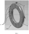
- FIG. 1 provides a schematic view of an illustrative embodiment of a bearing monitoring/analysis system.
- a bearing monitoring/analysis system may be configured to apply acoustic emission ("AE") technology to fluid film bearings.
- AE acoustic emission
- a bearing monitoring/analysis system may be configured such that it may collect data regarding the condition, operating parameters, performance, remaining useful operating period, and/or other information about a bearing (or other machinery component wherein a first surface moves relative to a second surface with a fluid medium therebetween) in a non-intrusive manner while the equipment associated with the bearing is operating and/or is in an assembled condition but not operating.
- a bearing monitoring/analysis system may be configured such that it may monitor the condition of other components of a bearing (or other piece of rotating equipment and/or machinery component as described in further detail below).
- Such other components include, but are not limited to, bearing pads, pad pivot surfaces (either on a surface of a pad 30 opposite to or other than the active surface 32), or another component and/or surface on a component of the bearing (e.g., carrier ring, piston, pad holding, and/or support structure, etc.) and/or other surfaces of a bearing or piece of rotating equipment in which there is relative movement between two surfaces without limitation unless so indicated in the following claims.
- a bearing monitoring/analysis system may be configured to track changes of the active surface of the bearing (among other data) from an early stage to offer information regarding the bearing not available in the prior art.
- data collected via AE which data includes but is not limited to hit driven data (data collected when the signal exceeds a specific threshold), time driven signal (data collected at a specific time interval), and waveform signal (data collected for from more than one source for a given length of time at a specific interval), and/or combinations thereof, may be interpreted and/or analyzed to detect differing degrees and/or types of bearing surface damage, type and/or specific location of damage, performance, conditions, etc., and may be used to predict the remaining life of the bearing such that preventative countermeasures may be advised accordingly.
- a bearing monitoring/analysis system may be configured to collect acoustic emission signal(s) from a bearing, analyze the signal(s) to gain useful information about the bearing and/or component thereof, and provide a suggested course of action considering the information gained.
- the information about the bearing and/or component thereof may be a type, severity, and/or location of damage to the bearing and/or component thereof (e.g., an active surface of a bearing, which active surface may be positioned on a pad).
- the information about the bearing and/or component thereof may be the predicted remaining life of the bearing and/or component thereof.
- a bearing monitoring/analysis system may be configured for nearly any different type of fluid film bearings, including but not limited to fixed geometry and tilt pad journal bearings; fixed geometry and tilt pad thrust bearings; fluid film bearings having relatively hard coatings on or adjacent to active surfaces thereof (which bearings may allow for relatively thinner films and higher operating temperatures) and/or fluid film bearings configured for use with rotating components having relatively hard coatings thereon; polymer bearings (either solid polymer pads or solid polymer bearing); babbitt bearings; bearings configured with pads having one or more jacking grooves (and/or hydrostatic lift pockets) thereon; Flexure Pivot ® bearings; fluid film bearings employing any type of lubrication (e.g., direct lubrication, flooded, evacuated, etc.); any type of lubricant (e.g., oil, water, air, process fluids, etc.); any fluid film bearing with alternative material(s) positioned on the pad or bearing surface regardless of the method/structure used for attaching the alternative material to the pads; any number of pads
- a bearing monitoring/analysis system may be used in conjunction with other technologies, including but not limited to ultrasound.
- the concepts of a bearing monitoring/analysis system may be applied to machinery components in contact with fluid other than bearings, such machinery components including but not limited to seals, valves and sliding surfaces, and/or rotating surfaces, etc. Accordingly, the scope of the present disclosure extends to any use of the bearing monitoring/analysis system to detect a condition/parameter of at least one of two or more adjacent surfaces that move relative to one another during operation of a machinery component without limitation unless so indicated in the following claims.
- bearing monitoring/analysis system extends to any fluid film bearing configured in any orientation, any number or configuration of pads 30 and/or active surface 32, and/or with different quantities of the various elements having different shapes and/or orientations, equally or unequally spaced from other elements unless otherwise indicated in the following claims. Additionally, the scope of the present disclosure is in no way limited by the specific shape, configuration, and/or dimensions of the above elements, and/or the relative quantities and/or positions thereof unless otherwise indicated in the following claims.
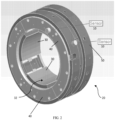
- a bearing monitoring/analysis system may be configured for use with a tilt pad journal bearing 20, as mentioned above.
- the tilt pad journal bearing 20 may have any number of pads 30 having any number of active surfaces 32 thereon without limitation unless so indicated in the following claims.
- a first sensor 10 may be positioned on a radial-external surface of the main body 50 and a second sensor 10 may be positioned on an end plate 40 (which constitutes an axial surface of the tilt pad journal bearing 20). Additional sensors 10 may also be included to increase monitoring system capability and to add redundancy, as further discussed below.
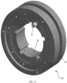
- a bearing monitoring/analysis system may be configured for use with a Flexure Pivot tilt pad journal bearing 20a, as mentioned above.
- the Flexure Pivot tilt pad journal bearing 20a may have any number of pads 30 having any number of active surfaces 32 thereon without limitation unless so indicated in the following claims.
- a first sensor 10 may be positioned on a radial-external surface of the main body 50 and a second sensor 10 may be positioned on an axial surface of the main body 50 and/or other axial surface of the Flexure Pivot tilt pad journal bearing 20a.
- additional sensors 10 may also be included to increase monitoring system capability and to add redundancy.
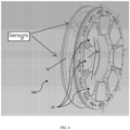
- one or more sensors may be attached to a pad or more than one pad.
- the sensor 10 is located on the pad. Additional sensors may be located on this pad or any other pad in the bearing. This application of a sensor on a pad is applicable to all types of bearings in addition to the Flexure Pivot embodiment without limitation unless so indicated in the following claims.
- a bearing monitoring/analysis system may be configured for use with a tilt pad thrust bearing 20b, as mentioned above.
- a first sensor 10 may be positioned on a radial-external surface of the main body 50 (and/or pad carrier ring) and a second sensor 10 may be positioned on an axial surface of the main body 50 and/or other axial surface of the tilt pad thrust bearing 20a (e.g., an axial surface of the pad carrier ring).
- a second sensor 10 is shown in this embodiment, but a single sensor 10 may be used, although this would not be in accordance with the claimed invention.
- any of the sensors 10 with respect to any pad 30 and/or active surface 32 may vary from one application of a bearing monitoring/analysis system to the next and is therefore in no way limiting to the scope thereof unless so indicated in the following claims.
- the number of sensors 10 may vary from application to application to increase bearing monitoring/analysis system capability and accuracy and to add redundancy, and is therefore in no way limiting to the scope thereof unless so indicated in the following claims.
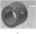
- a bearing monitoring/analysis system may be configured for use with a plane journal bearing 20c, as mentioned above.
- the plane journal bearing 20c may have any number of surface features (grooves, indentations, etc.) on the active surface(s) 32 and any number of lobes, faces, etc., thereof without limitation unless so indicated in the following claims.
- a first sensor 10 may be positioned on a radial-external surface of the main body 50 and a second sensor 10 may be positioned on an axial surface of the main body 50.
- additional sensors 10 may also be included to increase monitoring system capability and to add redundancy, and is therefore in no way limiting to the scope thereof unless so indicated in the following claims.
- a bearing monitoring/analysis system may be configured for use with a fixed geometry thrust bearing 20d, shown as a taper land thrust plate in FIG. 6 .
- the taper land thrust bearing 20d may have any number of surface features (grooves, tapers, flats, lands, indentations, etc.) on the active surfaces 32 and any number of feed grooves, faces, etc., thereon without limitation unless so indicated in the following claims.
- a first sensor 10 may be positioned on a radial-external surface of the main body 50 and a second sensor 10 may be positioned on an axial surface of the main body 50. Additional sensors 10 may also be included to increase monitoring system capability and to add redundancy.
- the bearing monitoring/analysis system may comprise just one sensor 10, and in other embodiments it may comprise more than two sensors 10.
- a first sensor 10 may be positioned 180 degrees from a second sensor 10.
- the bearing monitoring/analysis system may comprise three sensors 10 (or four, five, six, etc.) evenly spaced about the circumference of the bearing.
- a first sensor 10 may be positioned 90 degrees from a second sensor 10.
- a first axially positioned sensor 10 may be positioned 180 degrees from a second axially positioned sensor 10 and a first radially positioned sensor 10 may be positioned 180 degrees from a second radially positioned sensor 10.
- the optimal position of the sensor 10 with respect to pads 30, active surfaces 32, and/or other components of a bearing may vary from one application to the next, which position may depend at least upon the type of sensor 10 employed.
- one or more sensors may be engaged with an equipment housing associated with a bearing (or other piece of rotating equipment). Accordingly, although in FIGS. 2-6 one sensor 10 is oriented on an axial surface of a bearing and a second sensor 10 is oriented on a radial surface of a bearing, the scope of the present disclosure is not so limited and extends to any number of sensors 10 in any orientation with respect to the bearing and/or the other sensors 10 without limitation provided it falls within the scope of the invention defined by the following claims.
- the sensors 10 need not be affixed to the bearing itself for certain applications, but may be engaged with any structure that is suitably positioned with respect to the bearing such that the sensor 10 may detect/collect suitable AE from the point of interest without limitation unless so indicated in the following claims.
- a sensor 10 may be positioned adjacent to the bearing on a fixture and/or equipment housing to which the bearing is secured.
- a sensor 10 may be engaged with a bearing 20, 20a, 20b, 20c, component thereof, or other suitable structure using chemical adhesives, mechanical fasteners, magnets, and/or combinations thereof.
- a sensor 10 may be engaged with a bearing 20, 20a, 20b, 20c, component thereof, or other suitable structure using any suitable method and/or structure currently known or later developed without limitation unless so indicated in the following claims.
- Applicant has tested a bearing monitoring/analysis system on a 15-inch tilt pad journal bearing 20 to evaluate the effect of bearing speed and load on AE signals using a three-speed and three-load matrix.
- the specific equipment configuration, testing procedures/parameters, resulting test data, and other information regarding these experiments are not included for purposes of brevity.
- Applicant has tested a bearing monitoring/analysis system on a tilt pad thrust bearing 20b (model VSC 460) to evaluate the effect of bearing speed and load on AE signals and to evaluate the sensitivity of AE signals to pad damage.
- data was collected when all pads were in good operating conditions, after one pad had been intentionally damaged, and after two pads were intentionally damaged to compare the effect of pad damage on AE signals.
- the specific equipment configuration, testing procedures/parameters, resulting test data, and other information regarding these experiments are not included for purposes of brevity.
- a sensor configured as an R15a general purpose AE sensor 10 may be suitable for certain bearing monitoring/analysis systems.
- the scope of the present disclosure is not so limited and extends to any structure and/or method for detecting AE signals without limitation unless so indicated in the following claims.
- the materials used to construct the bearing monitoring/analysis system and/or components thereof will vary depending on the specific application thereof, but it is contemplated that polymers, synthetic materials, metals, metal alloys, ceramics, natural materials, and/or combinations thereof may be especially useful in some applications. Accordingly, the above-referenced elements may be constructed of any material known to those skilled in the art or later developed, which material is appropriate for the specific application of the bearing monitoring/analysis system without departing from the scope of the present invention is defined by the following claims.
- FIGS. 2-6 are drawn to accurate scale, any dimensions provided herein are for illustrative purposes only and in no way limit the scope of the present invention which is defined by the following claims. It should be noted that the bearing monitoring/analysis system, components thereof, and/or methods of using same according to the present disclosure are not limited to the specific embodiments pictured and described herein, but rather the scope of the present invention is defined by the claims herein. Modifications and alterations from the described embodiments will occur to those skilled in the art without departure from the scope of the present invention as defined by the claims.
Landscapes
- Engineering & Computer Science (AREA)
- General Engineering & Computer Science (AREA)
- Mechanical Engineering (AREA)
- Physics & Mathematics (AREA)
- Fluid Mechanics (AREA)
- Acoustics & Sound (AREA)
- General Physics & Mathematics (AREA)
- Testing Of Devices, Machine Parts, Or Other Structures Thereof (AREA)
- Sliding-Contact Bearings (AREA)
- Rolling Contact Bearings (AREA)
Claims (8)
- Système de surveillance/d'analyse de paliers comprenant :a. un palier à film de fluide ;b. un capteur d'émission acoustique (10) positionné de sorte qu'il soit adjacent audit palier, dans lequel ledit capteur d'émission acoustique est configuré pour collecter des données en provenance dudit palier à film de fluide pour reconnaître un patin endommagé (30) du palier à film de fluide, et le capteur d'émission acoustique est en outre défini comme étant engagé avec une surface radiale dudit palier à film de fluide ; etc. un second capteur d'émission acoustique (10), dans lequel ledit second capteur d'émission acoustique est configuré pour collecter des données en provenance dudit palier à film de fluide, et le second capteur d'émission acoustique est en outre défini comme étant engagé avec une surface axiale dudit palier à film de fluide.
- Système de surveillance/d'analyse de paliers selon la revendication 1, dans lequel ledit second capteur d'émission acoustique (10) est en outre défini comme étant positionné à approximativement centre-quatre-vingts (180) degrés par rapport audit premier capteur d'émission acoustique (10).
- Système de surveillance/d'analyse de paliers selon la revendication 1, dans lequel ledit premier capteur d'émission acoustique (10) est en outre défini en tant que capteur d'émission acoustique à usage général R15a.
- Système de surveillance/d'analyse de paliers selon la revendication 1, dans lequel ledit palier à film de fluide est en outre défini en tant que palier lisse à patins inclinables (20), palier lisse à patins inclinables par pivotement et flexion (20a), palier de butée à patins inclinables (20b), palier lisse plan (20c) ou palier à face de butée à parties coniques (20d).
- Procédé de surveillance/d'analyse de paliers comprenant :a. le positionnement d'un capteur d'émission acoustique (10) de sorte qu'il soit adjacent à un palier à film de fluide de manière à ce que le capteur d'émission acoustique soit engagé avec une surface radiale dudit palier à film de fluide, dans lequel ledit palier à film de fluide comprend une première surface et une seconde surface, et dans lequel ladite première surface et ladite seconde surface sont déplacées l'une par rapport à l'autre pendant le fonctionnement dudit palier à film de fluide ;b. le positionnement d'un second capteur d'émission acoustique (10) de telle sorte que le second capteur d'émission acoustique soit engagé avec une surface axiale dudit palier à film de fluide ;c. la collecte d'un signal via ledit capteur d'émission acoustique et ledit second capteur d'émission acoustique ;d. l'analyse dudit signal ;e. la reconnaissance d'un patin endommagé (30) dudit palier à film de fluide ; etf. la recommendation d'une action sur la base de ladite reconnaissance d'un patin endommagé.
- Procédé selon la revendication 5, dans lequel ledit capteur d'émission acoustique (10) est en outre défini comme étant engagé avec un logement d'équipement, dans lequel ledit logement d'équipement est engagé avec ledit palier à film de fluide.
- Procédé selon la revendication 5, dans lequel ledit palier à film de fluide est en outre défini en tant que palier de butée à patins inclinables (20b).
- Procédé selon la revendication 7, dans lequel ledit capteur d'émission acoustique (10) est en outre défini comme étant engagé avec un patin (30) dudit palier de butée à patins inclinables (20b).
Priority Applications (1)
| Application Number | Priority Date | Filing Date | Title |
|---|---|---|---|
| EP23191544.8A EP4293244A3 (fr) | 2017-05-22 | 2018-05-22 | Système de surveillance/analyse de palier |
Applications Claiming Priority (2)
| Application Number | Priority Date | Filing Date | Title |
|---|---|---|---|
| US201762509229P | 2017-05-22 | 2017-05-22 | |
| PCT/US2018/033945 WO2018217794A1 (fr) | 2017-05-22 | 2018-05-22 | Système de surveillance/analyse de palier |
Related Child Applications (1)
| Application Number | Title | Priority Date | Filing Date |
|---|---|---|---|
| EP23191544.8A Division EP4293244A3 (fr) | 2017-05-22 | 2018-05-22 | Système de surveillance/analyse de palier |
Publications (3)
| Publication Number | Publication Date |
|---|---|
| EP3631437A1 EP3631437A1 (fr) | 2020-04-08 |
| EP3631437A4 EP3631437A4 (fr) | 2021-05-12 |
| EP3631437B1 true EP3631437B1 (fr) | 2023-08-16 |
Family
ID=64395939
Family Applications (2)
| Application Number | Title | Priority Date | Filing Date |
|---|---|---|---|
| EP23191544.8A Pending EP4293244A3 (fr) | 2017-05-22 | 2018-05-22 | Système de surveillance/analyse de palier |
| EP18805748.3A Active EP3631437B1 (fr) | 2017-05-22 | 2018-05-22 | Système de surveillance/analyse de palier |
Family Applications Before (1)
| Application Number | Title | Priority Date | Filing Date |
|---|---|---|---|
| EP23191544.8A Pending EP4293244A3 (fr) | 2017-05-22 | 2018-05-22 | Système de surveillance/analyse de palier |
Country Status (8)
| Country | Link |
|---|---|
| US (4) | US11255750B2 (fr) |
| EP (2) | EP4293244A3 (fr) |
| JP (2) | JP7257970B2 (fr) |
| KR (1) | KR102651968B1 (fr) |
| CN (1) | CN110869759A (fr) |
| DK (1) | DK3631437T3 (fr) |
| ES (1) | ES2959957T3 (fr) |
| WO (1) | WO2018217794A1 (fr) |
Families Citing this family (10)
| Publication number | Priority date | Publication date | Assignee | Title |
|---|---|---|---|---|
| WO2018217794A1 (fr) | 2017-05-22 | 2018-11-29 | Waukesha Bearings Corporation | Système de surveillance/analyse de palier |
| CN109374297B (zh) * | 2018-12-13 | 2020-08-04 | 中国船舶重工集团公司第七〇四研究所 | 滑动推力轴承试验装置 |
| CN109991314B (zh) * | 2019-03-11 | 2020-12-29 | 清华大学 | 基于机器学习的机械密封状态判断方法、装置 |
| CN112362348A (zh) * | 2020-10-27 | 2021-02-12 | 华北电力大学(保定) | 一种带式输送机托辊轴承故障声学监测方法 |
| CN112403998B (zh) * | 2020-11-02 | 2023-07-14 | 安徽天富泵阀有限公司 | 一种机械制造系统用轴承磨损程度检测维护装置 |
| CN112555273A (zh) * | 2020-12-03 | 2021-03-26 | 武汉理工大学 | 一种磁悬浮和弹性箔片气体混合轴承实验平台 |
| US12078567B2 (en) * | 2021-05-27 | 2024-09-03 | The Heil Co. | Bearing pad monitoring systems and methods |
| CN114678732B (zh) * | 2022-03-10 | 2023-12-01 | 贵州乌江水电开发有限责任公司 | 一种智能弹性金属塑料推力瓦在线监测系统 |
| CN114674563B (zh) * | 2022-03-28 | 2022-11-11 | 昆明理工大学 | 一种单传感器轴承损伤故障定位方法 |
| CN118391296B (zh) * | 2024-06-27 | 2024-09-20 | 广东美的暖通设备有限公司 | 轴向动压轴承、离心压缩机以及控制方法 |
Citations (1)
| Publication number | Priority date | Publication date | Assignee | Title |
|---|---|---|---|---|
| US20160069775A1 (en) * | 2013-04-05 | 2016-03-10 | Aktiebolaget Skf | Method, computer program product & system |
Family Cites Families (47)
| Publication number | Priority date | Publication date | Assignee | Title |
|---|---|---|---|---|
| FI792659A7 (fi) | 1978-09-02 | 1981-01-01 | Masson Scott Thrissell Eng Ltd | Radan kelauskone ja kelateline sitä varten. |
| GB2094667B (en) | 1981-03-18 | 1984-07-18 | Glacier Metal The Co Ltd | Plain bearing and method of making same |
| JPS588823A (ja) | 1981-07-08 | 1983-01-19 | Hitachi Ltd | 軸受異常の診断方法 |
| JPS58150859A (ja) * | 1982-03-03 | 1983-09-07 | Hitachi Ltd | 回転体の亀裂診断装置 |
| US4526482A (en) | 1984-02-07 | 1985-07-02 | Ide Russell D | Hydrodynamic bearing surface for high loads and low viscosity lubricating fluids |
| JPS61182737A (ja) * | 1985-02-06 | 1986-08-15 | Omron Tateisi Electronics Co | 静圧空気軸受 |
| JPS61202714A (ja) | 1985-03-07 | 1986-09-08 | Nippon Kokan Kk <Nkk> | スラブエツジ部の加熱制御方式 |
| US5140858A (en) * | 1986-05-30 | 1992-08-25 | Koyo Seiko Co. Ltd. | Method for predicting destruction of a bearing utilizing a rolling-fatigue-related frequency range of AE signals |
| US5743654A (en) * | 1987-05-29 | 1998-04-28 | Kmc, Inc. | Hydrostatic and active control movable pad bearing |
| US5489155A (en) * | 1987-05-29 | 1996-02-06 | Ide; Russell D. | Tilt pad variable geometry bearings having tilting bearing pads and methods of making same |
| DE3875398T2 (de) | 1987-06-03 | 1993-04-08 | Kawasaki Steel Co | Vorrichtung zum feststellen von fehlern in lagern. |
| JP2918683B2 (ja) | 1990-07-24 | 1999-07-12 | 光洋精工株式会社 | 軸受疲労によるae信号の特定方法およびこの特定方法を用いた軸受破壊予知方法 |
| JP3321487B2 (ja) * | 1993-10-20 | 2002-09-03 | 株式会社日立製作所 | 機器/設備診断方法およびシステム |
| JPH07180721A (ja) * | 1993-12-24 | 1995-07-18 | Toshiba Corp | ティルティングパッドジャーナル軸受装置 |
| JPH09133577A (ja) | 1995-11-07 | 1997-05-20 | Hitachi Ltd | 異常接触検出方法および装置 |
| JPH09229822A (ja) | 1996-02-28 | 1997-09-05 | Kyocera Corp | 摺動試験機及びこれを用いた摺動試験方法 |
| US5918985A (en) * | 1997-09-19 | 1999-07-06 | Capstone Turbine Corporation | Compliant foil fluid thrust film bearing with a tilting pad underspring |
| JP3411807B2 (ja) | 1997-12-19 | 2003-06-03 | 株式会社三協精機製作所 | 動圧軸受装置の寿命検査装置及び検査方法 |
| JP2000266040A (ja) * | 1999-03-16 | 2000-09-26 | Eagle Ind Co Ltd | すべり軸受 |
| DE19947129A1 (de) * | 1999-09-30 | 2001-04-05 | Siemens Ag | Diagnosesystem und -verfahren, insbesondere für ein Ventil |
| US7337452B2 (en) | 2000-04-24 | 2008-02-26 | Dphi Acquisitions, Inc. | Tilt focus mechanism for an optical drive |
| US6967586B2 (en) * | 2000-10-20 | 2005-11-22 | Sankyo Seiki Mfg. Co., Ltd. | Bearing test method, bearing test device, bearing monitoring device and storage device |
| US6785081B2 (en) | 2000-11-02 | 2004-08-31 | Seagate Technology Llc | Fly height detector |
| JP2003222123A (ja) | 2002-01-25 | 2003-08-08 | Mitsubishi Heavy Ind Ltd | テーパランドスラスト軸受およびそれを備えた回転機械 |
| US7194802B2 (en) * | 2002-03-26 | 2007-03-27 | Seagate Technology Llc | Tool for certifying a head-gimbal assembly |
| JP2004150974A (ja) * | 2002-10-31 | 2004-05-27 | Nippon Densan Corp | 動作評価方法および動作評価装置 |
| JP2004205315A (ja) * | 2002-12-25 | 2004-07-22 | Nippon Densan Corp | 軸受構造体の動作評価方法 |
| DE10303877A1 (de) * | 2003-01-31 | 2004-08-12 | Fag Kugelfischer Ag | Verfahren zur Feststellung von Körperschallereignissen in einem Wälzlager |
| JP2004294348A (ja) * | 2003-03-28 | 2004-10-21 | Matsushita Electric Ind Co Ltd | 流体軸受け型モータの高温動作評価方法 |
| JP2006078203A (ja) * | 2004-09-07 | 2006-03-23 | Nsk Ltd | 転がり軸受及び転がり軸受の監視方法 |
| GB2430034A (en) * | 2005-05-04 | 2007-03-14 | Aes Eng Ltd | A condition monitoring device using acoustic emission sensors and data storage devices. |
| KR100764092B1 (ko) * | 2006-05-03 | 2007-10-09 | 한국원자력연구원 | 음향 방출 센서를 이용한 역지 밸브 건전성 감시 시스템 및방법 |
| RU2391656C2 (ru) * | 2008-06-27 | 2010-06-10 | Государственное образовательное учреждение высшего профессионального образования "Сибирский государственный университет путей сообщения" (СГУПС) | Акустико-эмиссионный способ диагностирования колец подшипников буксового узла железнодорожного транспортного средства и устройство для его осуществления |
| US8695405B2 (en) * | 2010-09-17 | 2014-04-15 | Bestsens Ag | Bearing, arrangement for determining properties of a lubricant in a bearing and method for determining properties of a lubricant in a bearing |
| WO2012040722A2 (fr) * | 2010-09-24 | 2012-03-29 | Waukesha Bearings Corporation | Palier à patin oscillant |
| KR20150004852A (ko) | 2012-04-24 | 2015-01-13 | 아크티에볼라게트 에스케이에프 | 베어링 조립체의 음향 방출 측정 |
| US9170238B2 (en) * | 2013-01-04 | 2015-10-27 | Fisher Controls International Llc | Acoustic fluid valve calibration |
| WO2014160493A1 (fr) * | 2013-03-13 | 2014-10-02 | Waukesha Bearings Corporation | Palier refroidi de bord de fuite |
| DE112014003588T5 (de) * | 2013-09-05 | 2016-05-19 | Borgwarner Inc. | Biegegelenk-Kippsegment-Radiallager zur Verwendung in einem Turbolader |
| CN105531576A (zh) | 2013-09-12 | 2016-04-27 | 西门子公司 | 用于监测技术上的装置、如机器或设备的方法和布置 |
| WO2015178821A1 (fr) | 2014-05-19 | 2015-11-26 | Aktiebolaget Skf | Capteur et procédé de détection d'émission acoustique provenant d'un palier |
| JP6038088B2 (ja) | 2014-09-22 | 2016-12-07 | 三菱重工業株式会社 | 軸受及び軸受パッド |
| JP2016118498A (ja) | 2014-12-22 | 2016-06-30 | 日本精工株式会社 | 異常診断装置、軸受装置、産業機械及び車両 |
| JP6227573B2 (ja) | 2015-02-06 | 2017-11-08 | 三菱重工業株式会社 | 軸受の異常診断装置及び異常診断方法 |
| CN206020034U (zh) * | 2016-08-25 | 2017-03-15 | 重庆市万州区分水永佳电子元件加工厂 | 一种转子轴承振动测试系统 |
| WO2018217794A1 (fr) | 2017-05-22 | 2018-11-29 | Waukesha Bearings Corporation | Système de surveillance/analyse de palier |
| US10969314B2 (en) * | 2019-07-05 | 2021-04-06 | Shandong University Of Science And Technology | Device and method for anchor bolt (cable) supporting structure test and anchoring system performance comprehensive experiment |
-
2018
- 2018-05-22 WO PCT/US2018/033945 patent/WO2018217794A1/fr not_active Ceased
- 2018-05-22 ES ES18805748T patent/ES2959957T3/es active Active
- 2018-05-22 JP JP2019564474A patent/JP7257970B2/ja active Active
- 2018-05-22 US US15/986,495 patent/US11255750B2/en active Active
- 2018-05-22 CN CN201880045135.6A patent/CN110869759A/zh active Pending
- 2018-05-22 DK DK18805748.3T patent/DK3631437T3/da active
- 2018-05-22 EP EP23191544.8A patent/EP4293244A3/fr active Pending
- 2018-05-22 EP EP18805748.3A patent/EP3631437B1/fr active Active
- 2018-05-22 KR KR1020197037920A patent/KR102651968B1/ko active Active
-
2022
- 2022-02-18 US US17/675,874 patent/US11841290B2/en active Active
- 2022-12-19 JP JP2022202016A patent/JP7592062B2/ja active Active
-
2023
- 2023-11-06 US US18/502,737 patent/US12422337B2/en active Active
-
2025
- 2025-08-20 US US19/305,356 patent/US20250369828A1/en active Pending
Patent Citations (1)
| Publication number | Priority date | Publication date | Assignee | Title |
|---|---|---|---|---|
| US20160069775A1 (en) * | 2013-04-05 | 2016-03-10 | Aktiebolaget Skf | Method, computer program product & system |
Also Published As
| Publication number | Publication date |
|---|---|
| CN110869759A (zh) | 2020-03-06 |
| KR20200010460A (ko) | 2020-01-30 |
| EP3631437A4 (fr) | 2021-05-12 |
| KR102651968B1 (ko) | 2024-03-26 |
| US20240068908A1 (en) | 2024-02-29 |
| WO2018217794A1 (fr) | 2018-11-29 |
| US11255750B2 (en) | 2022-02-22 |
| DK3631437T3 (da) | 2023-10-30 |
| EP3631437A1 (fr) | 2020-04-08 |
| US20180340862A1 (en) | 2018-11-29 |
| EP4293244A2 (fr) | 2023-12-20 |
| US11841290B2 (en) | 2023-12-12 |
| EP4293244A3 (fr) | 2024-04-10 |
| JP2020521133A (ja) | 2020-07-16 |
| US20220170821A1 (en) | 2022-06-02 |
| US20250369828A1 (en) | 2025-12-04 |
| JP7257970B2 (ja) | 2023-04-14 |
| ES2959957T3 (es) | 2024-02-29 |
| JP7592062B2 (ja) | 2024-11-29 |
| JP2023030064A (ja) | 2023-03-07 |
| US12422337B2 (en) | 2025-09-23 |
Similar Documents
| Publication | Publication Date | Title |
|---|---|---|
| EP3631437B1 (fr) | Système de surveillance/analyse de palier | |
| KR101579282B1 (ko) | 베어링의 내구성을 시험하기 위한 베어링의 시험 장치 | |
| Jamaludin et al. | Condition monitoring of slow-speed rolling element bearings using stress waves | |
| Rogers | The application of vibration signature analysis and acoustic emission source location to on-line condition monitoring of anti-friction bearings | |
| Jamaludin et al. | Monitoring extremely slow rolling element bearings: part I | |
| CN113195949B (zh) | 带有传感器的机械密封件 | |
| Daraz et al. | Detection and diagnosis of centrifugal pump bearing faults based on the envelope analysis of airborne sound signals | |
| JP2021032769A (ja) | 転がり軸受の状態監視方法及び状態監視装置 | |
| Gowid et al. | Characterisation of major fault detection features and techniques for the condition-based monitoring of high-speed centrifugal blowers | |
| Raharjo et al. | A comparative study of the monitoring of a self aligning spherical journal using surface vibration, airborne sound and acoustic emission | |
| Jotautiene et al. | Evaluation of bearing reliability of combine harvester straw chopper | |
| Rezaei | Fault Detection and Diagnosis on the rolling element bearing | |
| KR101789723B1 (ko) | 볼 베어링의 트라이볼로지 특성 시험 장치 | |
| Albers et al. | Simultaneous monitoring of rolling-element and journal bearings using analysis of structure-born ultrasound acoustic emissions | |
| Lacey | Using vibration analysis to detect early failure of bearings | |
| Łój et al. | Diagnostics of rotary vane vacuum pumps using signal processing, analysis and clustering methods | |
| EP4679052A1 (fr) | Dispositif de surveillance d'état | |
| GB2596406A (en) | Mechanical seal with sensor | |
| Erkaya et al. | Investigation of fan fault problems using vibration and noise analysis | |
| Alshimmeri | Diagnosis of low-speed bearing degradation using acoustic emission techniques | |
| Gill | A research on fault detection and diagnosis of rolling bearing | |
| Leichtweis dos Santos et al. | Monitoring of Lubrication Regime in Deep Groove Ball Bearings Using Acoustic Emission Sensors | |
| IBRAHIM | EXPERIMENTAL DETECTION OF LOCALIZED SURFACE DEFECTS IN BALL BEARINGS USING VIBRATION ANALYSIS | |
| JPS6272918A (ja) | ジヤ−ナル部損傷検出監視装置 | |
| Ayed et al. | Implementation of a rotating machines monitoring system based on lateral vibrations measurements |
Legal Events
| Date | Code | Title | Description |
|---|---|---|---|
| STAA | Information on the status of an ep patent application or granted ep patent |
Free format text: STATUS: THE INTERNATIONAL PUBLICATION HAS BEEN MADE |
|
| PUAI | Public reference made under article 153(3) epc to a published international application that has entered the european phase |
Free format text: ORIGINAL CODE: 0009012 |
|
| STAA | Information on the status of an ep patent application or granted ep patent |
Free format text: STATUS: REQUEST FOR EXAMINATION WAS MADE |
|
| 17P | Request for examination filed |
Effective date: 20191219 |
|
| AK | Designated contracting states |
Kind code of ref document: A1 Designated state(s): AL AT BE BG CH CY CZ DE DK EE ES FI FR GB GR HR HU IE IS IT LI LT LU LV MC MK MT NL NO PL PT RO RS SE SI SK SM TR |
|
| RIC1 | Information provided on ipc code assigned before grant |
Ipc: G01M 13/04 20190101ALI20210120BHEP Ipc: G01N 29/14 20060101AFI20210120BHEP |
|
| A4 | Supplementary search report drawn up and despatched |
Effective date: 20210414 |
|
| RIC1 | Information provided on ipc code assigned before grant |
Ipc: G01N 29/14 20060101AFI20210408BHEP Ipc: G01M 13/04 20190101ALI20210408BHEP |
|
| RIN1 | Information on inventor provided before grant (corrected) |
Inventor name: BLAIR, BARRY Inventor name: ZHOU, JIE |
|
| STAA | Information on the status of an ep patent application or granted ep patent |
Free format text: STATUS: EXAMINATION IS IN PROGRESS |
|
| 17Q | First examination report despatched |
Effective date: 20221012 |
|
| REG | Reference to a national code |
Ref country code: DE Ref legal event code: R079 Free format text: PREVIOUS MAIN CLASS: G01N0029140000 Ipc: F16C0017060000 Ref country code: DE Ref legal event code: R079 Ref document number: 602018055560 Country of ref document: DE Free format text: PREVIOUS MAIN CLASS: G01N0029140000 Ipc: F16C0017060000 |
|
| GRAP | Despatch of communication of intention to grant a patent |
Free format text: ORIGINAL CODE: EPIDOSNIGR1 |
|
| STAA | Information on the status of an ep patent application or granted ep patent |
Free format text: STATUS: GRANT OF PATENT IS INTENDED |
|
| RIC1 | Information provided on ipc code assigned before grant |
Ipc: F16C 17/02 20060101ALI20230113BHEP Ipc: G01M 13/045 20190101ALI20230113BHEP Ipc: F16C 17/24 20060101ALI20230113BHEP Ipc: F16C 17/06 20060101AFI20230113BHEP |
|
| INTG | Intention to grant announced |
Effective date: 20230214 |
|
| GRAS | Grant fee paid |
Free format text: ORIGINAL CODE: EPIDOSNIGR3 |
|
| P01 | Opt-out of the competence of the unified patent court (upc) registered |
Effective date: 20230607 |
|
| GRAA | (expected) grant |
Free format text: ORIGINAL CODE: 0009210 |
|
| STAA | Information on the status of an ep patent application or granted ep patent |
Free format text: STATUS: THE PATENT HAS BEEN GRANTED |
|
| AK | Designated contracting states |
Kind code of ref document: B1 Designated state(s): AL AT BE BG CH CY CZ DE DK EE ES FI FR GB GR HR HU IE IS IT LI LT LU LV MC MK MT NL NO PL PT RO RS SE SI SK SM TR |
|
| REG | Reference to a national code |
Ref country code: CH Ref legal event code: EP |
|
| REG | Reference to a national code |
Ref country code: DE Ref legal event code: R096 Ref document number: 602018055560 Country of ref document: DE |
|
| REG | Reference to a national code |
Ref country code: IE Ref legal event code: FG4D |
|
| REG | Reference to a national code |
Ref country code: DK Ref legal event code: T3 Effective date: 20231023 |
|
| REG | Reference to a national code |
Ref country code: LT Ref legal event code: MG9D |
|
| REG | Reference to a national code |
Ref country code: NL Ref legal event code: MP Effective date: 20230816 |
|
| REG | Reference to a national code |
Ref country code: AT Ref legal event code: MK05 Ref document number: 1600325 Country of ref document: AT Kind code of ref document: T Effective date: 20230816 |
|
| PG25 | Lapsed in a contracting state [announced via postgrant information from national office to epo] |
Ref country code: GR Free format text: LAPSE BECAUSE OF FAILURE TO SUBMIT A TRANSLATION OF THE DESCRIPTION OR TO PAY THE FEE WITHIN THE PRESCRIBED TIME-LIMIT Effective date: 20231117 |
|
| PG25 | Lapsed in a contracting state [announced via postgrant information from national office to epo] |
Ref country code: IS Free format text: LAPSE BECAUSE OF FAILURE TO SUBMIT A TRANSLATION OF THE DESCRIPTION OR TO PAY THE FEE WITHIN THE PRESCRIBED TIME-LIMIT Effective date: 20231216 |
|
| PG25 | Lapsed in a contracting state [announced via postgrant information from national office to epo] |
Ref country code: SE Free format text: LAPSE BECAUSE OF FAILURE TO SUBMIT A TRANSLATION OF THE DESCRIPTION OR TO PAY THE FEE WITHIN THE PRESCRIBED TIME-LIMIT Effective date: 20230816 Ref country code: RS Free format text: LAPSE BECAUSE OF FAILURE TO SUBMIT A TRANSLATION OF THE DESCRIPTION OR TO PAY THE FEE WITHIN THE PRESCRIBED TIME-LIMIT Effective date: 20230816 Ref country code: PT Free format text: LAPSE BECAUSE OF FAILURE TO SUBMIT A TRANSLATION OF THE DESCRIPTION OR TO PAY THE FEE WITHIN THE PRESCRIBED TIME-LIMIT Effective date: 20231218 Ref country code: NO Free format text: LAPSE BECAUSE OF FAILURE TO SUBMIT A TRANSLATION OF THE DESCRIPTION OR TO PAY THE FEE WITHIN THE PRESCRIBED TIME-LIMIT Effective date: 20231116 Ref country code: NL Free format text: LAPSE BECAUSE OF FAILURE TO SUBMIT A TRANSLATION OF THE DESCRIPTION OR TO PAY THE FEE WITHIN THE PRESCRIBED TIME-LIMIT Effective date: 20230816 Ref country code: LV Free format text: LAPSE BECAUSE OF FAILURE TO SUBMIT A TRANSLATION OF THE DESCRIPTION OR TO PAY THE FEE WITHIN THE PRESCRIBED TIME-LIMIT Effective date: 20230816 Ref country code: LT Free format text: LAPSE BECAUSE OF FAILURE TO SUBMIT A TRANSLATION OF THE DESCRIPTION OR TO PAY THE FEE WITHIN THE PRESCRIBED TIME-LIMIT Effective date: 20230816 Ref country code: IS Free format text: LAPSE BECAUSE OF FAILURE TO SUBMIT A TRANSLATION OF THE DESCRIPTION OR TO PAY THE FEE WITHIN THE PRESCRIBED TIME-LIMIT Effective date: 20231216 Ref country code: HR Free format text: LAPSE BECAUSE OF FAILURE TO SUBMIT A TRANSLATION OF THE DESCRIPTION OR TO PAY THE FEE WITHIN THE PRESCRIBED TIME-LIMIT Effective date: 20230816 Ref country code: GR Free format text: LAPSE BECAUSE OF FAILURE TO SUBMIT A TRANSLATION OF THE DESCRIPTION OR TO PAY THE FEE WITHIN THE PRESCRIBED TIME-LIMIT Effective date: 20231117 Ref country code: FI Free format text: LAPSE BECAUSE OF FAILURE TO SUBMIT A TRANSLATION OF THE DESCRIPTION OR TO PAY THE FEE WITHIN THE PRESCRIBED TIME-LIMIT Effective date: 20230816 Ref country code: AT Free format text: LAPSE BECAUSE OF FAILURE TO SUBMIT A TRANSLATION OF THE DESCRIPTION OR TO PAY THE FEE WITHIN THE PRESCRIBED TIME-LIMIT Effective date: 20230816 |
|
| PG25 | Lapsed in a contracting state [announced via postgrant information from national office to epo] |
Ref country code: PL Free format text: LAPSE BECAUSE OF FAILURE TO SUBMIT A TRANSLATION OF THE DESCRIPTION OR TO PAY THE FEE WITHIN THE PRESCRIBED TIME-LIMIT Effective date: 20230816 |
|
| REG | Reference to a national code |
Ref country code: ES Ref legal event code: FG2A Ref document number: 2959957 Country of ref document: ES Kind code of ref document: T3 Effective date: 20240229 |
|
| PG25 | Lapsed in a contracting state [announced via postgrant information from national office to epo] |
Ref country code: SM Free format text: LAPSE BECAUSE OF FAILURE TO SUBMIT A TRANSLATION OF THE DESCRIPTION OR TO PAY THE FEE WITHIN THE PRESCRIBED TIME-LIMIT Effective date: 20230816 Ref country code: RO Free format text: LAPSE BECAUSE OF FAILURE TO SUBMIT A TRANSLATION OF THE DESCRIPTION OR TO PAY THE FEE WITHIN THE PRESCRIBED TIME-LIMIT Effective date: 20230816 Ref country code: EE Free format text: LAPSE BECAUSE OF FAILURE TO SUBMIT A TRANSLATION OF THE DESCRIPTION OR TO PAY THE FEE WITHIN THE PRESCRIBED TIME-LIMIT Effective date: 20230816 Ref country code: CZ Free format text: LAPSE BECAUSE OF FAILURE TO SUBMIT A TRANSLATION OF THE DESCRIPTION OR TO PAY THE FEE WITHIN THE PRESCRIBED TIME-LIMIT Effective date: 20230816 Ref country code: SK Free format text: LAPSE BECAUSE OF FAILURE TO SUBMIT A TRANSLATION OF THE DESCRIPTION OR TO PAY THE FEE WITHIN THE PRESCRIBED TIME-LIMIT Effective date: 20230816 |
|
| REG | Reference to a national code |
Ref country code: DE Ref legal event code: R097 Ref document number: 602018055560 Country of ref document: DE |
|
| PLBE | No opposition filed within time limit |
Free format text: ORIGINAL CODE: 0009261 |
|
| STAA | Information on the status of an ep patent application or granted ep patent |
Free format text: STATUS: NO OPPOSITION FILED WITHIN TIME LIMIT |
|
| 26N | No opposition filed |
Effective date: 20240517 |
|
| PG25 | Lapsed in a contracting state [announced via postgrant information from national office to epo] |
Ref country code: IT Free format text: LAPSE BECAUSE OF FAILURE TO SUBMIT A TRANSLATION OF THE DESCRIPTION OR TO PAY THE FEE WITHIN THE PRESCRIBED TIME-LIMIT Effective date: 20230816 Ref country code: SI Free format text: LAPSE BECAUSE OF FAILURE TO SUBMIT A TRANSLATION OF THE DESCRIPTION OR TO PAY THE FEE WITHIN THE PRESCRIBED TIME-LIMIT Effective date: 20230816 |
|
| PG25 | Lapsed in a contracting state [announced via postgrant information from national office to epo] |
Ref country code: BG Free format text: LAPSE BECAUSE OF FAILURE TO SUBMIT A TRANSLATION OF THE DESCRIPTION OR TO PAY THE FEE WITHIN THE PRESCRIBED TIME-LIMIT Effective date: 20230816 |
|
| PG25 | Lapsed in a contracting state [announced via postgrant information from national office to epo] |
Ref country code: BG Free format text: LAPSE BECAUSE OF FAILURE TO SUBMIT A TRANSLATION OF THE DESCRIPTION OR TO PAY THE FEE WITHIN THE PRESCRIBED TIME-LIMIT Effective date: 20230816 |
|
| REG | Reference to a national code |
Ref country code: CH Ref legal event code: PL |
|
| PG25 | Lapsed in a contracting state [announced via postgrant information from national office to epo] |
Ref country code: MC Free format text: LAPSE BECAUSE OF FAILURE TO SUBMIT A TRANSLATION OF THE DESCRIPTION OR TO PAY THE FEE WITHIN THE PRESCRIBED TIME-LIMIT Effective date: 20230816 |
|
| PG25 | Lapsed in a contracting state [announced via postgrant information from national office to epo] |
Ref country code: LU Free format text: LAPSE BECAUSE OF NON-PAYMENT OF DUE FEES Effective date: 20240522 |
|
| PG25 | Lapsed in a contracting state [announced via postgrant information from national office to epo] |
Ref country code: MC Free format text: LAPSE BECAUSE OF FAILURE TO SUBMIT A TRANSLATION OF THE DESCRIPTION OR TO PAY THE FEE WITHIN THE PRESCRIBED TIME-LIMIT Effective date: 20230816 Ref country code: LU Free format text: LAPSE BECAUSE OF NON-PAYMENT OF DUE FEES Effective date: 20240522 Ref country code: CH Free format text: LAPSE BECAUSE OF NON-PAYMENT OF DUE FEES Effective date: 20240531 |
|
| REG | Reference to a national code |
Ref country code: BE Ref legal event code: MM Effective date: 20240531 |
|
| PG25 | Lapsed in a contracting state [announced via postgrant information from national office to epo] |
Ref country code: IE Free format text: LAPSE BECAUSE OF NON-PAYMENT OF DUE FEES Effective date: 20240522 |
|
| PG25 | Lapsed in a contracting state [announced via postgrant information from national office to epo] |
Ref country code: BE Free format text: LAPSE BECAUSE OF NON-PAYMENT OF DUE FEES Effective date: 20240531 |
|
| PG25 | Lapsed in a contracting state [announced via postgrant information from national office to epo] |
Ref country code: FR Free format text: LAPSE BECAUSE OF NON-PAYMENT OF DUE FEES Effective date: 20240531 |
|
| PGFP | Annual fee paid to national office [announced via postgrant information from national office to epo] |
Ref country code: DE Payment date: 20250416 Year of fee payment: 8 |
|
| PGFP | Annual fee paid to national office [announced via postgrant information from national office to epo] |
Ref country code: GB Payment date: 20250417 Year of fee payment: 8 Ref country code: ES Payment date: 20250603 Year of fee payment: 8 Ref country code: DK Payment date: 20250516 Year of fee payment: 8 |
|
| PG25 | Lapsed in a contracting state [announced via postgrant information from national office to epo] |
Ref country code: CY Free format text: LAPSE BECAUSE OF FAILURE TO SUBMIT A TRANSLATION OF THE DESCRIPTION OR TO PAY THE FEE WITHIN THE PRESCRIBED TIME-LIMIT; INVALID AB INITIO Effective date: 20180522 |
|
| PG25 | Lapsed in a contracting state [announced via postgrant information from national office to epo] |
Ref country code: HU Free format text: LAPSE BECAUSE OF FAILURE TO SUBMIT A TRANSLATION OF THE DESCRIPTION OR TO PAY THE FEE WITHIN THE PRESCRIBED TIME-LIMIT; INVALID AB INITIO Effective date: 20180522 |