EP3631876B1 - Batteriepackanordnung - Google Patents
Batteriepackanordnung Download PDFInfo
- Publication number
- EP3631876B1 EP3631876B1 EP17725762.3A EP17725762A EP3631876B1 EP 3631876 B1 EP3631876 B1 EP 3631876B1 EP 17725762 A EP17725762 A EP 17725762A EP 3631876 B1 EP3631876 B1 EP 3631876B1
- Authority
- EP
- European Patent Office
- Prior art keywords
- cells
- battery pack
- pack assembly
- cell
- conductive
- Prior art date
- Legal status (The legal status is an assumption and is not a legal conclusion. Google has not performed a legal analysis and makes no representation as to the accuracy of the status listed.)
- Active
Links
Images





Classifications
-
- H—ELECTRICITY
- H01—ELECTRIC ELEMENTS
- H01M—PROCESSES OR MEANS, e.g. BATTERIES, FOR THE DIRECT CONVERSION OF CHEMICAL ENERGY INTO ELECTRICAL ENERGY
- H01M50/00—Constructional details or processes of manufacture of the non-active parts of electrochemical cells other than fuel cells, e.g. hybrid cells
- H01M50/20—Mountings; Secondary casings or frames; Racks, modules or packs; Suspension devices; Shock absorbers; Transport or carrying devices; Holders
- H01M50/233—Mountings; Secondary casings or frames; Racks, modules or packs; Suspension devices; Shock absorbers; Transport or carrying devices; Holders characterised by physical properties of casings or racks, e.g. dimensions
- H01M50/24—Mountings; Secondary casings or frames; Racks, modules or packs; Suspension devices; Shock absorbers; Transport or carrying devices; Holders characterised by physical properties of casings or racks, e.g. dimensions adapted for protecting batteries from their environment, e.g. from corrosion
-
- H—ELECTRICITY
- H01—ELECTRIC ELEMENTS
- H01M—PROCESSES OR MEANS, e.g. BATTERIES, FOR THE DIRECT CONVERSION OF CHEMICAL ENERGY INTO ELECTRICAL ENERGY
- H01M50/00—Constructional details or processes of manufacture of the non-active parts of electrochemical cells other than fuel cells, e.g. hybrid cells
- H01M50/20—Mountings; Secondary casings or frames; Racks, modules or packs; Suspension devices; Shock absorbers; Transport or carrying devices; Holders
-
- H—ELECTRICITY
- H01—ELECTRIC ELEMENTS
- H01M—PROCESSES OR MEANS, e.g. BATTERIES, FOR THE DIRECT CONVERSION OF CHEMICAL ENERGY INTO ELECTRICAL ENERGY
- H01M10/00—Secondary cells; Manufacture thereof
- H01M10/42—Methods or arrangements for servicing or maintenance of secondary cells or secondary half-cells
- H01M10/48—Accumulators combined with arrangements for measuring, testing or indicating the condition of cells, e.g. the level or density of the electrolyte
- H01M10/482—Accumulators combined with arrangements for measuring, testing or indicating the condition of cells, e.g. the level or density of the electrolyte for several batteries or cells simultaneously or sequentially
-
- H—ELECTRICITY
- H01—ELECTRIC ELEMENTS
- H01M—PROCESSES OR MEANS, e.g. BATTERIES, FOR THE DIRECT CONVERSION OF CHEMICAL ENERGY INTO ELECTRICAL ENERGY
- H01M50/00—Constructional details or processes of manufacture of the non-active parts of electrochemical cells other than fuel cells, e.g. hybrid cells
- H01M50/20—Mountings; Secondary casings or frames; Racks, modules or packs; Suspension devices; Shock absorbers; Transport or carrying devices; Holders
- H01M50/204—Racks, modules or packs for multiple batteries or multiple cells
- H01M50/207—Racks, modules or packs for multiple batteries or multiple cells characterised by their shape
- H01M50/213—Racks, modules or packs for multiple batteries or multiple cells characterised by their shape adapted for cells having curved cross-section, e.g. round or elliptic
-
- H—ELECTRICITY
- H01—ELECTRIC ELEMENTS
- H01M—PROCESSES OR MEANS, e.g. BATTERIES, FOR THE DIRECT CONVERSION OF CHEMICAL ENERGY INTO ELECTRICAL ENERGY
- H01M50/00—Constructional details or processes of manufacture of the non-active parts of electrochemical cells other than fuel cells, e.g. hybrid cells
- H01M50/20—Mountings; Secondary casings or frames; Racks, modules or packs; Suspension devices; Shock absorbers; Transport or carrying devices; Holders
- H01M50/271—Lids or covers for the racks or secondary casings
-
- H—ELECTRICITY
- H01—ELECTRIC ELEMENTS
- H01M—PROCESSES OR MEANS, e.g. BATTERIES, FOR THE DIRECT CONVERSION OF CHEMICAL ENERGY INTO ELECTRICAL ENERGY
- H01M50/00—Constructional details or processes of manufacture of the non-active parts of electrochemical cells other than fuel cells, e.g. hybrid cells
- H01M50/50—Current conducting connections for cells or batteries
- H01M50/502—Interconnectors for connecting terminals of adjacent batteries; Interconnectors for connecting cells outside a battery casing
- H01M50/503—Interconnectors for connecting terminals of adjacent batteries; Interconnectors for connecting cells outside a battery casing characterised by the shape of the interconnectors
-
- H—ELECTRICITY
- H01—ELECTRIC ELEMENTS
- H01M—PROCESSES OR MEANS, e.g. BATTERIES, FOR THE DIRECT CONVERSION OF CHEMICAL ENERGY INTO ELECTRICAL ENERGY
- H01M50/00—Constructional details or processes of manufacture of the non-active parts of electrochemical cells other than fuel cells, e.g. hybrid cells
- H01M50/50—Current conducting connections for cells or batteries
- H01M50/502—Interconnectors for connecting terminals of adjacent batteries; Interconnectors for connecting cells outside a battery casing
- H01M50/509—Interconnectors for connecting terminals of adjacent batteries; Interconnectors for connecting cells outside a battery casing characterised by the type of connection, e.g. mixed connections
- H01M50/51—Connection only in series
-
- H—ELECTRICITY
- H01—ELECTRIC ELEMENTS
- H01M—PROCESSES OR MEANS, e.g. BATTERIES, FOR THE DIRECT CONVERSION OF CHEMICAL ENERGY INTO ELECTRICAL ENERGY
- H01M2220/00—Batteries for particular applications
- H01M2220/20—Batteries in motive systems, e.g. vehicle, ship, plane
-
- Y—GENERAL TAGGING OF NEW TECHNOLOGICAL DEVELOPMENTS; GENERAL TAGGING OF CROSS-SECTIONAL TECHNOLOGIES SPANNING OVER SEVERAL SECTIONS OF THE IPC; TECHNICAL SUBJECTS COVERED BY FORMER USPC CROSS-REFERENCE ART COLLECTIONS [XRACs] AND DIGESTS
- Y02—TECHNOLOGIES OR APPLICATIONS FOR MITIGATION OR ADAPTATION AGAINST CLIMATE CHANGE
- Y02E—REDUCTION OF GREENHOUSE GAS [GHG] EMISSIONS, RELATED TO ENERGY GENERATION, TRANSMISSION OR DISTRIBUTION
- Y02E60/00—Enabling technologies; Technologies with a potential or indirect contribution to GHG emissions mitigation
- Y02E60/10—Energy storage using batteries
Definitions
- the present invention relates to a battery pack assembly. Particularly, but not exclusively, the present invention relates to a lithium-ion battery pack assembly, and particularly to a large format battery pack assembly for example, for use with an electric vehicle such as an electric bike.
- Lithium-ion batteries are known in a variety of cell formats, cylindrical, prismatic and pouch cells are the most common varieties.
- a cylindrical cell the electrode is tightly wound about itself and the terminals are typically found at either end of the cylinder, the electrode being contained within a casing, typically made from aluminium. Due to the shape of the cell packing efficiency may be low but the provision of spaces between adjacent cells is useful for thermal management purposes.
- the electrodes of prismatic cells can be wound, stacked or folded and are usually located within an aluminium or plastics housing.
- the terminals are often on one end of the cell which, coupled with the shape of the cell improves packing efficiency.
- Pouch cells typically have stacked or folded electrodes encased in a flexible plastics casing.
- the terminals of pouch cells may extend from different sides of the pouch but conveniently they may both extend from one side, for example the top, of the pouch.
- a 'large format battery pack' A number of cells connected in series may be termed a 'large format battery pack'.
- the UN for example (e.g. in relation to the UN38.3 Procedure), states that a 'large battery' is one that has a mass in excess of 12 kg whereas some manufacturers specify that large batteries or large format battery packs have a power in excess of 1kWh.
- a large format battery pack is one with more than three cells (be they cylindrical, prismatic or pouch) connected in series.
- JP2008204986 discloses a battery assembly comprising plural columnar cells each having an end terminal and a side terminal. A bus bar is laser welded to the side terminal and end terminal.
- EP3053205 discloses an electrical battery module comprising a casing comprising a longitudinal body suitable for longitudinally receiving a plurality of electrical batteries, one next to the other, and an end cover coupled to one of the ends of said longitudinal body.
- WO2012082691 discloses a battery integration module which includes a first positioning plate for positioning multiple single batteries in formation for integration at one end of the battery formation, a second positioning plate for positioning the multiple single batteries in formation for integration at the opposite end of the battery formation, the first and second plates aligned together over the formation of batteries to form a battery holder frame.
- a battery pack assembly comprising two holding frames, wherein the two holding frames hold a plurality of cells between them, wherein at least two cells of the plurality of cells are connected by a conductor, and wherein the two holding frames are reversibly held with respect to one another in a closed condition by a fastening means or fastener, wherein the fastening means or fastener cause terminals of the two cells to be urged against the conductor and removal or loosening of the fastener or fastening means enables the cells to be freed from the assembly, at least one holding frame comprising one or more elastomeric protrusions and wherein the conductor is positioned such that at least a part of the conductor lies between one or more of the elastomeric protrusions and one or more cell terminals, such that with the frames in the closed condition the conductor is urged into contact by the elastomeric protrusions with said one or more terminals.
- the battery pack assembly comprises one or more conduction breaking means or conduction breaker.
- a conduction breaking means or conduction breaker may be positioned between each cell terminal, and the conductor or conductive means, which may be a conductive plate.
- a conduction breaking means or conduction breaker is provided between every cell terminal and the associated conductor or conductive means.
- the purpose of the one or more conduction breaking means of conduction breaker is to break the electrical circuit between a cell and the conductor or conductive means, when said cell exceeds a prescribed electrical and/or thermal limit.
- the conduction breaking means of conduction breaker severs the connection of the failed cell, i.e. a cell that has exceeded a prescribed electrical and/or thermal limit, isolating said failed cell from the rest of the battery pack assembly.
- the conduction breaking means or conduction breaker may comprise a first conductive portion for making contact with the cell terminal, a second conductive portion for making contact with the conductor or conductive means, an insulating portion, and a conduction breaker portion.
- the conduction breaking means or conduction breaker may comprise a metallic alloy, or a multi-metallic element and may comprise a bimetal fuse.
- the conduction breaker portion may comprise a low melting material, for example, a metal such as silver, or silver plated copper, tin, or zinc, or alloys of the same, which melts upon exceeding the electrical and/or thermal limit determined by the melting point of the material.
- the contact between the conduction breaking means or conduction breaker with both the conductive means one on major surface, and the cell terminal on the opposite major surface is increased upon 'tightening' of the fastening means when the battery pack assembly is under compression.
- the one or more conduction breaking means or conduction breaker allow the battery pack assembly to continue to function upon failure of an individual cell, by isolating the one or more failed cells from the other functioning cells in the battery pack assembly.
- the battery pack assembly comprises a monitoring means or monitor for monitoring the status of each cell.
- the monitoring means may comprise an integrated electrical circuit, which monitors the status of each cell by detecting the number of triggered conduction breaking means or conduction breakers resulting from failed cells, i.e. a cell that has exceeded a prescribed electrical and/or thermal limit, within the battery pack assembly.
- the monitoring means may comprise a method of determining the condition of the battery pack assembly. For example, the monitoring means may transmit data, which has been collected about the status of each cell within the assembly, to be fed through an algorithm to compare with the optimal function of the assembly, to determine the number of fully functioning cells and the number of failed cells.
- this provides information on the overall condition and remaining useful life of the battery pack assembly. More advantageously, this information may be used to inform the user of maintenance requirements, and of potential safety hazards from using an under-performing battery pack assembly.
- the battery pack assembly may be any format including laminates, pouch, cylindrical, and/or prismatic.
- the design of the assembly also allows for the integration of liquid cooling for high power applications.
- the battery pack assembly 1 comprises a plurality of lithium-ion cells 2, each cell being held longitudinally between two holding frames 3.
- the generally rectangular holding frames 3 (which may be made of a plastic material for example) each comprise a generally flat base 4, side walls 5 extending generally perpendicularly from the base 4, elastomeric members 6, conductive plates 7, screw slots 8 and battery terminals 9.
- the holding frames 3 are reversibly held together by fastening screws 10, with the plurality of cells 2 held in place between the holding frames 3 by the compressive force of the fastening screws 10, which each thread through a screw slot 8 in each of the two holding frames 3.
- the side walls 5 of the holding frame 3 each comprise a plurality of concave arcuate side wall sections 11.
- a plurality of base protrusions 12 also extend perpendicularly from the base 4.
- the side walls of the base protrusions 12 may comprise a plurality of concave arcuate protrusion wall sections 13.
- Each concave arcuate side wall section 11 in combination with at least one concave arcuate protrusion wall section 13 thereby defines part of a generally cylindrical region 14 to seat a cylindrical cell 2.
- the screw slots 8 for the receiving of the fastening screws 10 are positioned in some of the base protrusions 12.
- the base 4 further comprises a plurality of recesses 15, in each of which may sit an elastomeric member 6 forming an elastomeric protrusion. This may be of rubber, a rubber compound, a plastics material and so on.
- the protrusions may be otherwise shaped to accommodate other cell shapes, eg generally planar intersections or square to accommodate rectangular or square cells. In the past the cells may be of any desired shape.
- Figure 3 shows the holding frame of Figure 3 , wherein each of the recesses 15 is fitted with an elastomeric member 6.
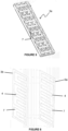
- Figure 4 shows one possible arrangement of the conductive plates 7 to be inserted into a holding frame 3a.
- three cells would be electrically connected by each of the two linear conductive plates 7a, and six cells would be electrically connected by each of the four U-shaped conductive plates 7b.
- An opposing holding frame 3b (not shown) will be associated with an arrangement of conductive plates 7 complementary to the arrangement of conductive plates 7 inserted into the holding frame 3a, such that all of the plurality of cells 2 are electrically connected in a desired arrangement, for example in series, in parallel, or in series-parallel (i.e. wherein one set of cells in parallel are connected in series with one or more further sets of cells also in parallel).
- the end plates 7a each have projections 16 which connect with the battery terminals 9 on one of the holding frames 3, to enable the plurality of cells 2 to be connected to an external circuit.
- Figure 5 shows the holding frame 3a in combination with conductive plates 7 of Figure 4 .
- the conductive plates 7 are positioned across the base 4 of the holding frame 3a and are positioned to extend across a plurality of generally cylindrical regions 14, so as to electrically connect a plurality of cells 2 when the plurality of cells 2 are each positioned within a respective generally cylindrical region 14 and held between the holding frames 3.
- the compression caused by the tightening of the fastening screws 10 encourages contact between the plurality of cells 2 and the conductive plates 7, wherein the conductive plates 7 are further urged towards the plurality of cells 2 by the elastomeric members 6 urging the conductive plates 7 upwardly, ensuring robust electrical contacts.
- Figure 6 shows one example of how the conductive plates 7 may be positioned across the bases 4 of each of the two holding frames 3a and 3b to form a complete circuit (once the plurality of cells 2 are inserted and compressed by the fastening means).
- Each of the plurality of cells 2 must be orientated such that the polarity of each cell 2 opposes the polarity of the adjacent cell in the series (for example, the first cell in the series is positioned with the positive terminal positioned towards holding frame 3a, the second cell in the series is positioned with the positive terminal positioned towards holding frame 3b, and so on).
- terminals 9 on the holding frame 3 connecting to tabs 16 of the conductive plates 7
- other connecting means may be provided to connect the arrangement of batteries to an external circuit.
- Conductive means and/or elastomeric protrusions may be necessary just on one side of a cell array in some embodiments.
- one of the holding frames may be an access lid. This can be removed or perhaps opened to enable access to cells within, for replacement or maintenance of the cells.
- the access lid may have conductive means and perhaps also elastomeric portions or may in other embodiments not be provided with these, in which case the electrical connections are all made at the side of the cells distal from the access lid.
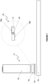
- FIG. 7 shows an embodiment of a section of a battery pack assembly 71 according to the invention.
- the battery pack assembly 71 comprises a plurality of cells 72 (only one shown), a pair of holding frames 73 (only one shown), a conductive plate 74, and a conduction breaking means or conduction breaker 75.
- the conduction breaker 75 comprises a first conductive portion 76a, a second conductive portion 76b, an insulating portion or body 77, and a conduction breaker 78.
- the first conductive portion 76a makes contact with a terminal of the cell 72.
- the second conductive portion 76b makes contact with the conductive plate 74.
- the conduction breaker 78 is positioned between the first conductive portion 76a and the second conductive portion 76b, within the insulating portion 77.
- the first conductive portion 76a, the conduction breaker 78, and the second conductive portion 78b are electrically connected. In use, electrical current flows from the cell 72, through the first conductive portion 76a, the conduction breaker 78, and the second conductive portion 78b, to the conductive plate 74. If the electrical or thermal limit of the conduction breaker 78 is exceeded, then the conduction breaker 78 will break the electrical circuit between a cell 72 and the conductive plate 74.
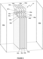
- FIG 8 shows an exploded view of an embodiment of a prismatic cell battery pack assembly 81.
- the prismatic cell battery pack assembly 81 comprises a number of cells 82a, 82b, 82c...82z (where the total number of cells is chosen by design requirements), a top holding frame 83a, a base holding frame 83b, a first conductive plate 84a, a second conductive plate 84b, and a set of elastomeric protrusions 85a.
- the cells 82a-82z each comprise a respective cell terminal 86a-86z.
- the set of elastomeric protrusions 85a are positioned between the holding frame 83a and the conductive plate 84a.
- FIG 12 shows an embodiment of the battery pack assembly 120.
- the battery pack 120 comprises a first holding frame 121, a second holding frame 122, a third holding frame 123, a first set of cells 124A, and a second set of cells 124B.
- the second holding frame 122 has a first side 122A and a second side 122B.
- the holding frames 100 or 110 of Figures 10 and 11 may be used in this embodiment as the first, second, or third holding frames 121, 122, 123.
- the first set of cells 124A are accommodated in recesses (not shown) provided in the first holding frame 121 and recesses (not shown) provided in the first side 122A of the second holding frame 122.
- the number of cells used in the first set of cells 124A or the second set of cells 124B is not limited to that shown in Figure 12 , and may be selected as appropriate for the application.
Landscapes
- Chemical & Material Sciences (AREA)
- Chemical Kinetics & Catalysis (AREA)
- Electrochemistry (AREA)
- General Chemical & Material Sciences (AREA)
- Engineering & Computer Science (AREA)
- Manufacturing & Machinery (AREA)
- Battery Mounting, Suspending (AREA)
Claims (15)
- Batteriepackanordnung (1), umfassend zwei Halterahmen (3), wobei die zwei Halterahmen (3) eine Vielzahl von Zellen (2) zwischen sich halten, wobei mindestens zwei Zellen aus der Vielzahl von Zellen (2) durch einen Leiter (7) verbunden sind und wobei die zwei Halterahmen (3) durch ein Befestigungsmittel oder Befestigungselement (10) reversibel in einem geschlossenen Zustand zueinander gehalten sind, wobei das Befestigungsmittel oder Befestigungselement (10) bewirkt, dass Anschlüsse der zwei Zellen (2) gegen den Leiter (7) gedrückt werden, und das Entfernen oder Lösen des Befestigungselements oder Befestigungsmittels (10) es ermöglicht, dass die Zellen (2) von der Anordnung (1) befreit werden, wobei mindestens ein Halterahmen (3) einen oder mehrere elastomere Vorsprünge (6) umfasst, und dadurch gekennzeichnet, dass der Leiter (7) derart positioniert ist, dass mindestens ein Teil des Leiters (7) zwischen einem oder mehreren der elastomeren Vorsprünge (6) und einem oder mehreren Zellanschlüssen (9) liegt, sodass der Leiter (7) im geschlossenen Zustand der Rahmen (3) durch die elastomeren Vorsprünge (6) in Kontakt mit dem einen oder den mehreren Anschlüssen (9) gedrückt wird.
- Batteriepackanordnung (1) nach Anspruch 1, wobei der Leiter (7) die zwei Zellen (2) in Reihe verbindet.
- Batteriepackanordnung (1) nach Anspruch 1 oder 2, wobei der Vielzahlsatz von Zellen (2) zwischen zwei parallelen Halterahmen (3) positioniert ist, wobei jede Zelle (2) in Längsrichtung oder seitlich zwischen den zwei Halterahmen (3) aufgrund des Befestigungselements oder Befestigungsmittels (10) gehalten wird.
- Batteriepackanordnung (1) nach einem der vorhergehenden Ansprüche, wobei einer der Rahmen (3) ein Zugangsdeckel ist oder einen Zugangsdeckel bereitstellt, der geöffnet oder entfernt werden kann, um Zugang zu den Zellen (2) zu erhalten.
- Batteriepackanordnung (1) nach einem der vorhergehenden Ansprüche, wobei mindestens ein Halterahmen (3) einen oder mehrere Anschlüsse (9) zur Verbindung mit einer externen elektrischen Schaltung umfasst.
- Batteriepackanordnung (1) nach einem der vorhergehenden Ansprüche, wobei der Leiter oder das leitfähige Mittel (7) eine oder mehrere leitfähige Platten umfasst.
- Batteriepackanordnung nach Anspruch 6, wobei eine oder mehrere der leitfähigen Platten (7) Mittel umfassen, um ein Mittel zum Verbinden der leitfähigen Platten (7) mit einer externen Schaltung bereitzustellen, wobei das Mittel zum Verbinden der leitfähigen Platten (7) mit der externen Schaltung mindestens einen Überstand einer leitenden Platte umfassen kann.
- Batteriepackanordnung (1) nach einem der vorhergehenden Ansprüche, wobei mindestens ein Halterahmen (3) eine Basis (4) und Seitenwände (5) umfasst, wobei sich Basisvorsprünge (12) senkrecht von der Basis (4) erstrecken.
- Batteriepackanordnung (1) nach Anspruch 8, wobei die Wände des einen oder der mehreren Basisvorsprünge (12) eine Vielzahl von konkaven bogenförmigen Abschnitten (13) umfassen und wobei jeder konkave bogenförmige Vorsprungswandabschnitt (13) einen Krümmungsradius aufweisen kann, der im Allgemeinen gleich dem Radius einer der Vielzahl von Zellen (2) ist, sodass eine Zelle (2) zumindest teilweise von dem konkaven bogenförmigen Abschnitt (13) aufgenommen wird.
- Batteriepackanordnung (1) nach Anspruch 8 oder 9, wobei mindestens eine der Halterahmenseitenwände (5) jeweils eine Vielzahl von konkaven bogenförmigen Abschnitten (11) umfasst.
- Batteriepackanordnung (1) nach Anspruch 10, wobei die Zellen (2) im Allgemeinen zylindrisch sind und die Vielzahl von konkaven bogenförmigen Abschnitten (11) jeweils einen Krümmungsradius aufweisen, der im Wesentlichen gleich dem Radius einer der Vielzahl von Zellen (2) ist, sodass eine Zelle (2) zumindest teilweise von dem konkaven bogenförmigen Abschnitt (11) aufgenommen wird.
- Batteriepackanordnung (1) nach Anspruch 11, wenn abhängig von einem der Ansprüche 8, 9 oder 10, wobei der eine oder die mehreren Basisvorsprünge (12) derart positioniert sind, dass die konkaven bogenförmigen Seitenwandabschnitte (11) und die konkaven bogenförmigen Vorsprungswandabschnitte (13) zumindest einen Teil einer Vielzahl von im Allgemeinen zylindrischen Bereichen (14) definieren, um jeweils eine zylindrische Zelle (2) zu setzen, wobei jeder elastomere Vorsprung (6) zentral in einem im Allgemeinen zylindrischen Bereich (14) positioniert sein kann.
- Batteriepackanordnung (1) nach einem der vorhergehenden Ansprüche, wobei das Befestigungsmittel (10) eine Vielzahl von Befestigungsschrauben umfasst, jeder Halterahmen (3) eine Vielzahl von Gewindelöchern umfassen kann, durch die jede Befestigungsschraube eingedreht werden kann, und jedes der Gewindelöcher in einem Basisvorsprung positioniert sein kann.
- Batteriepackanordnung (1, 71) nach einem der vorhergehenden Ansprüche, ferner umfassend einen oder mehrere reibschlüssig gehaltene Leitungsunterbrecher (75), wobei der oder jeder Leitungsunterbrecher (75) zwischen einem Zellanschluss (72) und dem Leiter oder leitfähigen Mittel (74) positioniert sein kann.
- Batteriepackanordnung (1, 71) nach Anspruch 14, wobei der oder jeder Leitungsunterbrecher (75) einen ersten leitfähigen Abschnitt (76a) zum Herstellen eines Kontakts mit dem Zellenanschluss (72), einen zweiten leitfähigen Abschnitt (76b) zum Herstellen eines Kontakts mit dem Leiter oder leitfähigen Mittel (74), einen isolierenden Abschnitt (77) und einen Leitungsunterbrecherabschnitt (78) umfasst, wobei der Leitungsunterbrecherabschnitt (78) ein niedrigschmelzendes Material, beispielsweise ein Metall wie Silber oder versilbertes Kupfer, Zinn oder Zink oder Legierungen derselben, umfassen kann, das beim Überschreiten der elektrischen und/oder thermischen Grenze schmilzt, die durch den Schmelzpunkt des Materials oder einer BiMetall-Sicherung bestimmt ist.
Applications Claiming Priority (1)
| Application Number | Priority Date | Filing Date | Title |
|---|---|---|---|
| PCT/GB2017/051433 WO2018215725A1 (en) | 2017-05-23 | 2017-05-23 | Battery pack assembly |
Publications (3)
| Publication Number | Publication Date |
|---|---|
| EP3631876A1 EP3631876A1 (de) | 2020-04-08 |
| EP3631876B1 true EP3631876B1 (de) | 2025-04-16 |
| EP3631876C0 EP3631876C0 (de) | 2025-04-16 |
Family
ID=58772597
Family Applications (1)
| Application Number | Title | Priority Date | Filing Date |
|---|---|---|---|
| EP17725762.3A Active EP3631876B1 (de) | 2017-05-23 | 2017-05-23 | Batteriepackanordnung |
Country Status (4)
| Country | Link |
|---|---|
| US (3) | US11469466B2 (de) |
| EP (1) | EP3631876B1 (de) |
| CN (1) | CN110663122A (de) |
| WO (1) | WO2018215725A1 (de) |
Families Citing this family (8)
| Publication number | Priority date | Publication date | Assignee | Title |
|---|---|---|---|---|
| EP3631876B1 (de) | 2017-05-23 | 2025-04-16 | Aceleron Limited | Batteriepackanordnung |
| GB201821086D0 (en) * | 2018-12-21 | 2019-02-06 | Aceleron Ltd | Battery pack assembly |
| DE102019131200A1 (de) * | 2019-11-19 | 2021-05-20 | Bayerische Motoren Werke Aktiengesellschaft | Kraftfreies Batteriemodul für eine Traktionsbatterie, Verfahren zum Herstellen eines Batteriemoduls, Traktionsbatterie sowie elektrisch antreibbares Kraftfahrzeug |
| AT523340B1 (de) * | 2020-01-09 | 2022-12-15 | Miba Battery Systems Gmbh | Spannvorrichtung |
| EP4360945B1 (de) * | 2020-02-04 | 2025-09-03 | Volvo Penta Corporation | Fahrzeugenergiespeichermodul, batteriepack und fahrzeug |
| KR102882948B1 (ko) * | 2020-08-07 | 2025-11-07 | 주식회사 엘지에너지솔루션 | 바이메탈을 이용한 전류차단장치를 가진 배터리 팩 및 그 작동 방법 |
| GB2605787B (en) | 2021-04-12 | 2024-10-16 | Upgrade Tech Engineering Ltd | A battery cell holder |
| KR102853689B1 (ko) * | 2025-01-22 | 2025-09-02 | 주식회사 오빌 | 배터리 셀의 전기적 연결 안정성이 향상된 배터리 모듈 |
Citations (1)
| Publication number | Priority date | Publication date | Assignee | Title |
|---|---|---|---|---|
| US20100304201A1 (en) * | 2007-05-15 | 2010-12-02 | Olivier Caumont | Module for electric energy storage assemblies for ageing detection of said assemblies |
Family Cites Families (24)
| Publication number | Priority date | Publication date | Assignee | Title |
|---|---|---|---|---|
| JP4610362B2 (ja) | 2005-02-04 | 2011-01-12 | 三洋電機株式会社 | パック電池 |
| JP5162919B2 (ja) * | 2007-02-16 | 2013-03-13 | パナソニック株式会社 | 蓄電ユニット |
| FR2920913B1 (fr) | 2007-09-06 | 2009-11-13 | Pellenc Sa | Batterie constituee d'une pluralite de cellules positionnees et reliees entre elles, sans soudure. |
| JP4960839B2 (ja) * | 2007-11-12 | 2012-06-27 | 本田技研工業株式会社 | 車両用バッテリ冷却装置 |
| KR101016596B1 (ko) | 2009-01-29 | 2011-02-22 | 강정욱 | 셀 상호간 복합연결망으로 구성된 셀 카트리지 |
| AT508742B1 (de) | 2009-09-10 | 2011-07-15 | Norman Neuhold | Einsatz für ein akkumulatorteil |
| KR101097258B1 (ko) | 2009-12-04 | 2011-12-21 | 삼성에스디아이 주식회사 | 배터리 팩 |
| US9184430B2 (en) * | 2010-12-13 | 2015-11-10 | Andrew E. Kalman | Battery pack for integrating multiple single batteries |
| AU2012373356B2 (en) | 2012-03-12 | 2016-02-25 | Chung Peng Liew | Non-welded battery module |
| CN202503048U (zh) | 2012-04-01 | 2012-10-24 | 山东精工电子科技有限公司 | 圆柱锂电池支架 |
| CN103682191B (zh) | 2012-09-06 | 2016-08-24 | 阿提瓦公司 | 框架具有点胶挡止的电池组件 |
| FR3011390B1 (fr) * | 2013-09-30 | 2017-02-17 | Thierry Claudel | Module de batterie electrique |
| KR101653307B1 (ko) * | 2014-01-13 | 2016-09-01 | 주식회사 엘지화학 | 단위모듈들을 포함하는 전지모듈 어셈블리 |
| CN104393211B (zh) | 2014-12-05 | 2016-08-24 | 江苏天鹏电源有限公司 | 一种用分体式支架进行连接且减震效果好的36v电池包 |
| US20160172653A1 (en) | 2014-12-15 | 2016-06-16 | Nec Energy Solutions, Inc. | Battery containment |
| JP6245159B2 (ja) * | 2014-12-17 | 2017-12-13 | 株式会社オートネットワーク技術研究所 | 電池配線モジュール |
| EP3241254B1 (de) | 2015-04-16 | 2018-04-25 | Neuss, Wilhem | Batteriemodul |
| US20160344072A1 (en) | 2015-05-19 | 2016-11-24 | Go-Tech Energy Co., Ltd. | Rechargeable battery module |
| GB2545267A (en) * | 2015-12-11 | 2017-06-14 | Cummins Carlton | Battery pack assembly |
| US9620763B1 (en) * | 2016-03-07 | 2017-04-11 | GS Yuasa Lithium Power Inc. | Connector assembly with integrated sense and balance line protection for multi-cell batteries |
| KR101985387B1 (ko) | 2016-03-14 | 2019-06-03 | 신흥에스이씨주식회사 | 내구성이 우수한 배터리팩 |
| US20180123096A1 (en) | 2016-10-27 | 2018-05-03 | Shawn Allan McCarty | Means for Assembling Cylindrical Batteries into a Modular and Rebuildable Battery Pack |
| TWI613856B (zh) | 2016-11-08 | 2018-02-01 | 免銲的圓柱型電池組裝置 | |
| EP3631876B1 (de) | 2017-05-23 | 2025-04-16 | Aceleron Limited | Batteriepackanordnung |
-
2017
- 2017-05-23 EP EP17725762.3A patent/EP3631876B1/de active Active
- 2017-05-23 CN CN201780091207.6A patent/CN110663122A/zh active Pending
- 2017-05-23 WO PCT/GB2017/051433 patent/WO2018215725A1/en not_active Ceased
- 2017-05-23 US US16/615,194 patent/US11469466B2/en active Active
-
2022
- 2022-09-01 US US17/901,301 patent/US11677113B2/en active Active
-
2023
- 2023-05-03 US US18/142,895 patent/US12087954B2/en active Active
Patent Citations (1)
| Publication number | Priority date | Publication date | Assignee | Title |
|---|---|---|---|---|
| US20100304201A1 (en) * | 2007-05-15 | 2010-12-02 | Olivier Caumont | Module for electric energy storage assemblies for ageing detection of said assemblies |
Also Published As
| Publication number | Publication date |
|---|---|
| US12087954B2 (en) | 2024-09-10 |
| US20200227697A1 (en) | 2020-07-16 |
| CN110663122A (zh) | 2020-01-07 |
| US11469466B2 (en) | 2022-10-11 |
| EP3631876A1 (de) | 2020-04-08 |
| US20230275294A1 (en) | 2023-08-31 |
| US11677113B2 (en) | 2023-06-13 |
| US20220416342A1 (en) | 2022-12-29 |
| WO2018215725A1 (en) | 2018-11-29 |
| EP3631876C0 (de) | 2025-04-16 |
Similar Documents
| Publication | Publication Date | Title |
|---|---|---|
| US11677113B2 (en) | Battery pack assembly | |
| US20220059898A1 (en) | Battery pack assembly | |
| US7951483B2 (en) | Assembled battery with inner and outer frames | |
| JP5220588B2 (ja) | 安全性が向上した中型又は大型の改良バッテリーパック | |
| KR101106544B1 (ko) | 기구물체결방식의 유닛팩 조합형 셀 카트리지 | |
| KR100850866B1 (ko) | 전지팩 제조용 프레임 부재 | |
| US20220077534A1 (en) | Battery pack assembly | |
| US20140205874A1 (en) | Flexible fusible link, systems, and methods | |
| JP2012515421A (ja) | 電気化学的エネルギー貯蔵装置 | |
| EP2197065B1 (de) | Anschlussvorrichtung für Batteriezellen mit Folienanschlussklemmen | |
| GB2545567A (en) | Battery pack assembly | |
| KR20130129838A (ko) | 축전 장치의 제조 방법, 스페이서, 및 축전 장치 | |
| US20240356165A1 (en) | Battery pack assembly | |
| KR20190045611A (ko) | 리튬배터리 팩에 사용하는 pcb 부스바 | |
| KR101047991B1 (ko) | 수용부가 형성된 엔드프레임을 갖는 리튬 2차 전지 케이스 및 수용부가 형성된 엔드프레임을 갖는 리튬 2차 전지 셋 | |
| US20250141022A1 (en) | Battery | |
| US20250158191A1 (en) | Battery pack assembly | |
| US20240421441A1 (en) | Battery Pack and Jig for Battery Pack Manufacture | |
| WO2022195605A1 (en) | Swappable modular battery pack and assembly thereof |
Legal Events
| Date | Code | Title | Description |
|---|---|---|---|
| STAA | Information on the status of an ep patent application or granted ep patent |
Free format text: STATUS: UNKNOWN |
|
| STAA | Information on the status of an ep patent application or granted ep patent |
Free format text: STATUS: THE INTERNATIONAL PUBLICATION HAS BEEN MADE |
|
| PUAI | Public reference made under article 153(3) epc to a published international application that has entered the european phase |
Free format text: ORIGINAL CODE: 0009012 |
|
| STAA | Information on the status of an ep patent application or granted ep patent |
Free format text: STATUS: REQUEST FOR EXAMINATION WAS MADE |
|
| 17P | Request for examination filed |
Effective date: 20191217 |
|
| AK | Designated contracting states |
Kind code of ref document: A1 Designated state(s): AL AT BE BG CH CY CZ DE DK EE ES FI FR GB GR HR HU IE IS IT LI LT LU LV MC MK MT NL NO PL PT RO RS SE SI SK SM TR |
|
| AX | Request for extension of the european patent |
Extension state: BA ME |
|
| RAP1 | Party data changed (applicant data changed or rights of an application transferred) |
Owner name: ACELERON LIMITED |
|
| RIN1 | Information on inventor provided before grant (corrected) |
Inventor name: CHANDAN, AMRIT Inventor name: CUMMINS, CARLTON |
|
| DAV | Request for validation of the european patent (deleted) | ||
| DAX | Request for extension of the european patent (deleted) | ||
| REG | Reference to a national code |
Ref country code: DE Ref legal event code: R079 Free format text: PREVIOUS MAIN CLASS: H01M0002100000 Ipc: H01M0010480000 Ref country code: DE Ref legal event code: R079 Ref document number: 602017088931 Country of ref document: DE Free format text: PREVIOUS MAIN CLASS: H01M0002100000 Ipc: H01M0010480000 |
|
| GRAP | Despatch of communication of intention to grant a patent |
Free format text: ORIGINAL CODE: EPIDOSNIGR1 |
|
| STAA | Information on the status of an ep patent application or granted ep patent |
Free format text: STATUS: GRANT OF PATENT IS INTENDED |
|
| RIC1 | Information provided on ipc code assigned before grant |
Ipc: H01M 50/271 20210101ALI20241022BHEP Ipc: H01M 10/48 20060101AFI20241022BHEP |
|
| INTG | Intention to grant announced |
Effective date: 20241112 |
|
| GRAS | Grant fee paid |
Free format text: ORIGINAL CODE: EPIDOSNIGR3 |
|
| GRAA | (expected) grant |
Free format text: ORIGINAL CODE: 0009210 |
|
| STAA | Information on the status of an ep patent application or granted ep patent |
Free format text: STATUS: THE PATENT HAS BEEN GRANTED |
|
| AK | Designated contracting states |
Kind code of ref document: B1 Designated state(s): AL AT BE BG CH CY CZ DE DK EE ES FI FR GB GR HR HU IE IS IT LI LT LU LV MC MK MT NL NO PL PT RO RS SE SI SK SM TR |
|
| REG | Reference to a national code |
Ref country code: GB Ref legal event code: FG4D |
|
| REG | Reference to a national code |
Ref country code: CH Ref legal event code: EP |
|
| REG | Reference to a national code |
Ref country code: IE Ref legal event code: FG4D |
|
| REG | Reference to a national code |
Ref country code: DE Ref legal event code: R096 Ref document number: 602017088931 Country of ref document: DE |
|
| U01 | Request for unitary effect filed |
Effective date: 20250516 |
|
| U07 | Unitary effect registered |
Designated state(s): AT BE BG DE DK EE FI FR IT LT LU LV MT NL PT RO SE SI Effective date: 20250530 |
|
| U20 | Renewal fee for the european patent with unitary effect paid |
Year of fee payment: 9 Effective date: 20250530 |
|
| PG25 | Lapsed in a contracting state [announced via postgrant information from national office to epo] |
Ref country code: ES Free format text: LAPSE BECAUSE OF FAILURE TO SUBMIT A TRANSLATION OF THE DESCRIPTION OR TO PAY THE FEE WITHIN THE PRESCRIBED TIME-LIMIT Effective date: 20250416 |
|
| PG25 | Lapsed in a contracting state [announced via postgrant information from national office to epo] |
Ref country code: NO Free format text: LAPSE BECAUSE OF FAILURE TO SUBMIT A TRANSLATION OF THE DESCRIPTION OR TO PAY THE FEE WITHIN THE PRESCRIBED TIME-LIMIT Effective date: 20250716 Ref country code: GR Free format text: LAPSE BECAUSE OF FAILURE TO SUBMIT A TRANSLATION OF THE DESCRIPTION OR TO PAY THE FEE WITHIN THE PRESCRIBED TIME-LIMIT Effective date: 20250717 |
|
| PG25 | Lapsed in a contracting state [announced via postgrant information from national office to epo] |
Ref country code: PL Free format text: LAPSE BECAUSE OF FAILURE TO SUBMIT A TRANSLATION OF THE DESCRIPTION OR TO PAY THE FEE WITHIN THE PRESCRIBED TIME-LIMIT Effective date: 20250416 |
|
| PG25 | Lapsed in a contracting state [announced via postgrant information from national office to epo] |
Ref country code: HR Free format text: LAPSE BECAUSE OF FAILURE TO SUBMIT A TRANSLATION OF THE DESCRIPTION OR TO PAY THE FEE WITHIN THE PRESCRIBED TIME-LIMIT Effective date: 20250416 |
|
| PG25 | Lapsed in a contracting state [announced via postgrant information from national office to epo] |
Ref country code: RS Free format text: LAPSE BECAUSE OF FAILURE TO SUBMIT A TRANSLATION OF THE DESCRIPTION OR TO PAY THE FEE WITHIN THE PRESCRIBED TIME-LIMIT Effective date: 20250716 |
|
| PG25 | Lapsed in a contracting state [announced via postgrant information from national office to epo] |
Ref country code: IS Free format text: LAPSE BECAUSE OF FAILURE TO SUBMIT A TRANSLATION OF THE DESCRIPTION OR TO PAY THE FEE WITHIN THE PRESCRIBED TIME-LIMIT Effective date: 20250816 |
|
| REG | Reference to a national code |
Ref country code: CH Ref legal event code: H13 Free format text: ST27 STATUS EVENT CODE: U-0-0-H10-H13 (AS PROVIDED BY THE NATIONAL OFFICE) Effective date: 20251223 |
|
| PG25 | Lapsed in a contracting state [announced via postgrant information from national office to epo] |
Ref country code: SM Free format text: LAPSE BECAUSE OF FAILURE TO SUBMIT A TRANSLATION OF THE DESCRIPTION OR TO PAY THE FEE WITHIN THE PRESCRIBED TIME-LIMIT Effective date: 20250416 |
|
| PG25 | Lapsed in a contracting state [announced via postgrant information from national office to epo] |
Ref country code: CH Free format text: LAPSE BECAUSE OF NON-PAYMENT OF DUE FEES Effective date: 20250531 |
|
| PG25 | Lapsed in a contracting state [announced via postgrant information from national office to epo] |
Ref country code: CZ Free format text: LAPSE BECAUSE OF FAILURE TO SUBMIT A TRANSLATION OF THE DESCRIPTION OR TO PAY THE FEE WITHIN THE PRESCRIBED TIME-LIMIT Effective date: 20250416 |
|
| PG25 | Lapsed in a contracting state [announced via postgrant information from national office to epo] |
Ref country code: SK Free format text: LAPSE BECAUSE OF FAILURE TO SUBMIT A TRANSLATION OF THE DESCRIPTION OR TO PAY THE FEE WITHIN THE PRESCRIBED TIME-LIMIT Effective date: 20250416 |
|
| PG25 | Lapsed in a contracting state [announced via postgrant information from national office to epo] |
Ref country code: MC Free format text: LAPSE BECAUSE OF FAILURE TO SUBMIT A TRANSLATION OF THE DESCRIPTION OR TO PAY THE FEE WITHIN THE PRESCRIBED TIME-LIMIT Effective date: 20250416 |
|
| PLBE | No opposition filed within time limit |
Free format text: ORIGINAL CODE: 0009261 |
|
| STAA | Information on the status of an ep patent application or granted ep patent |
Free format text: STATUS: NO OPPOSITION FILED WITHIN TIME LIMIT |
|
| REG | Reference to a national code |
Ref country code: CH Ref legal event code: L10 Free format text: ST27 STATUS EVENT CODE: U-0-0-L10-L00 (AS PROVIDED BY THE NATIONAL OFFICE) Effective date: 20260225 |
|
| 26N | No opposition filed |
Effective date: 20260119 |
|
| GBPC | Gb: european patent ceased through non-payment of renewal fee |
Effective date: 20250716 |
|
| PG25 | Lapsed in a contracting state [announced via postgrant information from national office to epo] |
Ref country code: GB Free format text: LAPSE BECAUSE OF NON-PAYMENT OF DUE FEES Effective date: 20250716 |
|
| PG25 | Lapsed in a contracting state [announced via postgrant information from national office to epo] |
Ref country code: IE Free format text: LAPSE BECAUSE OF NON-PAYMENT OF DUE FEES Effective date: 20250523 |
|
| PG25 | Lapsed in a contracting state [announced via postgrant information from national office to epo] |
Ref country code: CY Free format text: LAPSE BECAUSE OF FAILURE TO SUBMIT A TRANSLATION OF THE DESCRIPTION OR TO PAY THE FEE WITHIN THE PRESCRIBED TIME-LIMIT Effective date: 20250416 |