EP3632006B1 - Extension de la dynamique de détection de signaux tdd et extension de la robustesse vis-à-vis de signaux volatils - Google Patents
Extension de la dynamique de détection de signaux tdd et extension de la robustesse vis-à-vis de signaux volatils Download PDFInfo
- Publication number
- EP3632006B1 EP3632006B1 EP18728154.8A EP18728154A EP3632006B1 EP 3632006 B1 EP3632006 B1 EP 3632006B1 EP 18728154 A EP18728154 A EP 18728154A EP 3632006 B1 EP3632006 B1 EP 3632006B1
- Authority
- EP
- European Patent Office
- Prior art keywords
- downlink
- time
- downlink signal
- threshold
- signal
- Prior art date
- Legal status (The legal status is an assumption and is not a legal conclusion. Google has not performed a legal analysis and makes no representation as to the accuracy of the status listed.)
- Active
Links
Images


Classifications
-
- H—ELECTRICITY
- H04—ELECTRIC COMMUNICATION TECHNIQUE
- H04B—TRANSMISSION
- H04B7/00—Radio transmission systems, i.e. using radiation field
- H04B7/14—Relay systems
- H04B7/15—Active relay systems
- H04B7/155—Ground-based stations
- H04B7/15557—Selecting relay station operation mode, e.g. between amplify and forward mode, decode and forward mode or FDD - and TDD mode
-
- H—ELECTRICITY
- H04—ELECTRIC COMMUNICATION TECHNIQUE
- H04B—TRANSMISSION
- H04B7/00—Radio transmission systems, i.e. using radiation field
- H04B7/24—Radio transmission systems, i.e. using radiation field for communication between two or more posts
- H04B7/26—Radio transmission systems, i.e. using radiation field for communication between two or more posts at least one of which is mobile
- H04B7/2643—Radio transmission systems, i.e. using radiation field for communication between two or more posts at least one of which is mobile using time-division multiple access [TDMA]
- H04B7/2656—Radio transmission systems, i.e. using radiation field for communication between two or more posts at least one of which is mobile using time-division multiple access [TDMA] for structure of frame, burst
-
- H—ELECTRICITY
- H04—ELECTRIC COMMUNICATION TECHNIQUE
- H04J—MULTIPLEX COMMUNICATION
- H04J3/00—Time-division multiplex systems
- H04J3/02—Details
- H04J3/14—Monitoring arrangements
-
- H—ELECTRICITY
- H04—ELECTRIC COMMUNICATION TECHNIQUE
- H04L—TRANSMISSION OF DIGITAL INFORMATION, e.g. TELEGRAPHIC COMMUNICATION
- H04L5/00—Arrangements affording multiple use of the transmission path
- H04L5/14—Two-way operation using the same type of signal, i.e. duplex
- H04L5/1461—Suppression of signals in the return path, i.e. bidirectional control circuits
-
- H—ELECTRICITY
- H04—ELECTRIC COMMUNICATION TECHNIQUE
- H04W—WIRELESS COMMUNICATION NETWORKS
- H04W52/00—Power management, e.g. Transmission Power Control [TPC] or power classes
- H04W52/02—Power saving arrangements
- H04W52/0209—Power saving arrangements in terminal devices
- H04W52/0225—Power saving arrangements in terminal devices using monitoring of external events, e.g. the presence of a signal
- H04W52/0245—Power saving arrangements in terminal devices using monitoring of external events, e.g. the presence of a signal according to signal strength
-
- H—ELECTRICITY
- H04—ELECTRIC COMMUNICATION TECHNIQUE
- H04W—WIRELESS COMMUNICATION NETWORKS
- H04W52/00—Power management, e.g. Transmission Power Control [TPC] or power classes
- H04W52/04—Transmission power control [TPC]
- H04W52/06—TPC algorithms
- H04W52/14—Separate analysis of uplink or downlink
- H04W52/143—Downlink power control
-
- H—ELECTRICITY
- H04—ELECTRIC COMMUNICATION TECHNIQUE
- H04W—WIRELESS COMMUNICATION NETWORKS
- H04W56/00—Synchronisation arrangements
- H04W56/0055—Synchronisation arrangements determining timing error of reception due to propagation delay
- H04W56/0065—Synchronisation arrangements determining timing error of reception due to propagation delay using measurement of signal travel time
- H04W56/007—Open loop measurement
- H04W56/0075—Open loop measurement based on arrival time vs. expected arrival time
- H04W56/008—Open loop measurement based on arrival time vs. expected arrival time detecting arrival of signal based on received raw signal
-
- H—ELECTRICITY
- H04—ELECTRIC COMMUNICATION TECHNIQUE
- H04B—TRANSMISSION
- H04B1/00—Details of transmission systems, not covered by a single one of groups H04B3/00 - H04B13/00; Details of transmission systems not characterised by the medium used for transmission
-
- H—ELECTRICITY
- H04—ELECTRIC COMMUNICATION TECHNIQUE
- H04B—TRANSMISSION
- H04B7/00—Radio transmission systems, i.e. using radiation field
- H04B7/02—Diversity systems; Multi-antenna system, i.e. transmission or reception using multiple antennas
- H04B7/022—Site diversity; Macro-diversity
-
- H—ELECTRICITY
- H04—ELECTRIC COMMUNICATION TECHNIQUE
- H04W—WIRELESS COMMUNICATION NETWORKS
- H04W88/00—Devices specially adapted for wireless communication networks, e.g. terminals, base stations or access point devices
- H04W88/08—Access point devices
- H04W88/085—Access point devices with remote components
Definitions
- Certain aspects and examples are directed to switching sub-systems for a distributed antenna system ("DAS") configured for time division duplexing (“TDD”) operations.
- DAS distributed antenna system
- TDD time division duplexing
- the DAS can use a switching sub-system to switch between an uplink mode for communicating TDD signals in an uplink direction and a downlink mode for communicating TDD signals in a downlink direction.
- the switching sub-system can automatically determine switching times for the DAS based on determining whether a signal level for downlink signals exceeds a threshold level.
- One or more switches of the switching sub-system can switch a remote antenna unit of the DAS to the downlink mode by selectively connecting one or more components of the downlink path in the remote antenna unit and disconnecting one or more components of a corresponding uplink path in the remote antenna unit.
- the switching sub-system can include a switching control module that detects the downlink/uplink ratio of base stations in communication with the DAS.
- the switching control module can determine an initial clock setting based on the downlink/uplink ratio.
- the initial clock setting can determine the timing for sending command signals to the switches of the switching sub-system that instruct the switches to switch the DAS between an uplink mode and a downlink mode.
- the switching control module can also optimize a clock setting that controls switching times for the switches. Optimizing the switching times can maximize or otherwise improve data throughput via the DAS.
- the switching control module can optimize the clock setting by determining start or end times for respective downlink subframes transmitted via the downlink path.
- the switching control module can determine the start or end times based on when signal power measurements for the downlink path exceed a threshold signal power.
- the switching control module can statistically determine a switching time adjustment based on a set of switching time differentials between the initial clock setting and the determined start or end times for the downlink subframes. For example, the switching time adjustment may be the statistical mean of the set of switching time differentials.
- the switching control module can update the clock setting based on the switching time adjustment.
- FIG. 1 is a block diagram depicting an example of DAS 100 having a TDD switching sub-system 110 according to an aspect of the present disclosure.
- the DAS 100 can include a master unit 102 in communication with remote antenna units 104a, 104b and with base stations 101a, 101b.
- different base stations can communicate signals associated with different telecommunication operators.
- the DAS 100 can be positioned in a geographical area (e.g., a stadium, an office building, etc.) to extend wireless communication coverage of the base stations 101a, 101b into geographical coverage areas 108a, 108b.
- a geographical area e.g., a stadium, an office building, etc.
- the master unit 102 can communicate signals between the base stations 101a, 101b and the remote antenna units 104a, 104b.
- An example of a master unit 102 is a wireless conversion station.
- the master unit 102 and remote antenna unit(s) 104a, 104b can communicate via any suitable communication medium.
- the communication medium can be any suitable medium for providing a serial communication link between the master unit 102 and the remote antenna unit 104a, 104b.
- the communication medium can be an optical fiber.
- the communication medium can include copper cables, microwave links, etc.
- the master unit 102 and remote antenna units 104a, 104b can include analog-to-digital and digital-to-analog converters for digital communication over a serial link.
- FIG. 1 depicts a single master unit 102 in communication with two base stations 101a, 101b and two remote antenna units 104a, 104b.
- a distributed antenna system 100 can include any number of master units and any number of remote antenna units for communicating signals between any number of base stations or other signal sources and any number of coverage areas.
- a DAS 100 can include other devices in addition to master units and remote antenna units.
- the DAS 100 may include a base station router or other interface device that receives signals from base stations 101a, 101b and provides the signals to the master unit 102.
- the DAS 100 may include one or more extension units that communicate signals between the master unit 102 and the remote antenna units 104a, 104b.
- the DAS 100 can be configured for TDD operations that support multiple operators communicating signals via the DAS 100.
- the DAS 100 can switch between an uplink mode for communicating TDD signals in an uplink direction and a downlink mode for communicating TDD signals in a downlink direction.
- the remote antenna units 104a, 104b can respectively include TDD switching sub-systems 110a, 110b used to connect components of the downlink path in response to detecting downlink signals having signal levels exceeding a threshold level.
- the TDD switching sub-systems 110a, 110b can analyze downlink signals to determine if signal levels for the downlink signals exceed specified threshold levels.
- Each of the TDD switching sub-systems 110a, 110b can include switches that switch a respective one of the remote antenna units 104a, 104b to the downlink mode by selectively connecting one or more components of the downlink path in the remote antenna unit and disconnecting one or more components of a corresponding uplink path in the remote antenna unit.
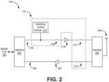
- FIG. 2 is a block diagram depicting an example of a remote antenna unit 104 with a TDD switching sub-system 110 according to an aspect of the present disclosure.
- downlink signals received from the master unit 102 via an interface 202 can traverse a downlink path 204 and can be coupled to an antenna 209 via an interface 208 for transmission to communication devices in a coverage area.
- uplink signals received by the antenna 209 can be coupled to an uplink path 206 via the interface 208 and can traverse the uplink path 206 for transmission to the master unit 102 via the interface 202.
- the switching control module 210 can control the operation of the switches 212, 214, 216 to selectively allow communication of downlink signals via the downlink path 204 or uplink signals via the uplink path 206.
- the switching control module 210 can control the switches 212, 214, 216 by sending switching signals to the switches 212, 214, 216 or devices actuating the switches 212, 214, 216 (not depicted in FIG. 2 ).
- the switching control module 210 can be communicatively coupled to the switches 212, 214, 216 or devices actuating the switches 212, 214, 216 via any suitable mechanism.
- the switching control module 210 can provide switching signals that cause the switches 212, 214 to be opened and the switch 216 to be closed, thereby opening the downlink path 204 between the interfaces 202, 208 and completing the uplink path 206 between the interfaces 202, 208.
- Any suitable switches 212, 214, 216 can be used.
- Non-limiting example of suitable switches 212, 214, 216 include RF switches, RF attenuators, digital attenuators in a digital signal path, digital switches interrupting a digital signal in a digital signal path, etc.
- FIG. 2 depicts the switching control module 210 as a separate module coupled to the downlink path 204 for illustrative purposes, other implementations are possible.
- the downlink path 204 may include one or more digital signal processing components, such as a processing device (e.g., an application-specific integrated circuit ("ASIC"), a field-programmable gate array (“FPGA”), etc.).
- ASIC application-specific integrated circuit
- FPGA field-programmable gate array
- the functions of the switching control module 210 can be performed by the processing device using digital downlink signals in the downlink path 204 between the interfaces 202, 208.
- the switching control module 210 can include a measurement receiver 302, a comparator 304, and a processor 306 communicatively coupled to a memory 308.
- Method 600 includes setting a threshold signal power to a first value (block 602).
- the threshold signal power can be provided as an input to the comparator 304 or can be used directly by the processor 306.
- the first value of the threshold signal power is set to be a maximum value usable for the DAS.
- the maximum value of the threshold signal power can correspond to a value that is just below the lowest power level of the high signals of the downlink signal in a downlink signal only subframe. This is shown in FIGS.
- Method 600 further includes determining the downlink signal time using the first value of the threshold signal power (block 604).
- the determined downlink signal time corresponds to the time elapsed from when the downlink signal is first detected (shown as 654) to when the downlink is no longer detected (shown as 656).
- the downlink signal is first detected when the downlink signal power of the signal from the base station, which can provided to the comparator 304 or directly to the processor 306, exceeds the threshold signal power.
- the threshold signal power (THmax) is too high to detect the downlink signal in the DwPTS, so the determined downlink signal time (t 1 ) is shorter than the actual downlink signal time (t 0 ).
- Method 600 further includes determining a difference between the measured downlink signal times determined using the different values of the threshold signal power (block 610). In particular, for the first instance of the determination, the difference between the measured downlink time determined using the first value (shown as t 1 ) of the threshold signal power and the measured downlink signal time determined using the reduced value of the threshold signal power (shown as tx') is determined.
- Method 600 further includes determining whether the determined difference exceeds a threshold time (block 612).
- the threshold time is a predetermined, fixed value. If a determined downlink signal time is not correct, it can be assumed that at least one symbol was cut off. In other words, the determined downlink signal time is not correct if another downlink signal time was measured with a different offset time of more than one symbol, which is approximately 70 ⁇ s for LTE. Therefore, in exemplary embodiments, the threshold time is selected based on the duration of one symbol. In particular, the threshold time is selected to be less than the duration of one symbol by a desired offset. In the context of LTE, one symbol has a duration of approximately 70 ⁇ s, so the threshold time can be selected to be less than 70 ⁇ s. For example, the threshold time is set at approximately 60 ⁇ s for LTE signals.
- method 600 proceeds with adjusting the threshold signal power to a further reduced value (block 606) and determining the downlink time using the further reduced value of the threshold signal power (block 608).
- Method 600 proceeds with determining the difference between the measured downlink signal times determined using the different values of the threshold signal power (block 610) and determining whether the difference exceeds the time threshold (612). The difference is determined for each iteration of the method steps and the two most recent measured downlink signal times are compared. The sequence can be repeated sequentially until the difference between the measured downlink signal times does not exceed the threshold.
- the switching control engine 310 can access data describing the timing and different downlink/uplink ratios for different TDD configurations.
- the switching control engine 310 can select a TDD configuration based on a standardized downlink/uplink ratio in a telecommunication standard, such as a 3rd Generation Partnership Project ("3GPP") specification. Selecting the TDD configuration based on a standardized downlink/uplink ratio in a telecommunication standard can minimize or otherwise reduce errors with respect to incorrect switching intervals. If the downlink signal time determined using the reduced value matches a valid downlink time, then it is validated.
- 3GPP 3rd Generation Partnership Project
- method 600 proceeds with adjusting the threshold signal power to a further reduced value (block 606) and determining the downlink time using the further reduced value of the threshold signal power (block 608) similar to when the determined difference exceeds the threshold time as discussed above.
- Method 600 provides a more accurate determination of the threshold signal power compared to the calibrated threshold signal power based on estimation in the factory setting.
- the threshold signal power is calibrated to ensure detection of all components of the downlink signal for synchronizing the TDD switching sub-system with the TDD signals provided by the base stations.
- the discrepancies may be a result of some SSF configurations having the last portion of the DwPTS used for data channels only, which do not include synchronization signals.
- the duration of the downlink signal can be varied due to adding throughput to the downlink, which includes extending the duration with respect to the data load.
- FIG. 8 is a flow chart of an example method 700 for operating the switching control module of the TDD switching sub-system according to an aspect of the present disclosure.
- the embodiment of method 700 shown in FIG. 8 is described here as being implemented using the switching control module of the TDD switching sub-system 210 of FIGS. 2-3 , though it is to be understood that other embodiments can be implemented in other ways.
- Method 700 optionally includes detecting a start time of the downlink signal (block 701).
- the switching control engine 310 can receive or otherwise access data describing power measurements by the measurement receiver 302.
- the switching control engine 310 can detect the start time for a respective downlink signal based on a signal indicative of the signal power in the downlink path 204 exceeding the threshold signal power.
- a signal can be provided by a comparator 304 or directly from the processor 306 as discussed above.
- Method 700 proceeds with determining whether a predetermined time window of an expected transition from a downlink signal to an uplink signal is reached (702).
- the predetermined time window is selected using an initial clock setting for the switching control module 210 based on the offline mode described above with respect to FIG. 6 .
- the determined downlink signal time identified using the set threshold signal power can be used for the initial clock setting.
- the start of the time window can correspond to a fixed period of time before the expected switching time based on the initial clock setting. The fixed period of time before the expected switching time is sufficient so the final transition from high to low when the downlink signal ends is detected.
- the start of the time window can be approximately 60 ⁇ s prior to the expected switching time.
- the time window can be used to determine when the processor 306 begins looking for a transition from the downlink signal to the uplink signal.
- the processor 306 operation is interrupted until the time window is reached.
- the processor 306 does not listen to the output of the comparator 304 or output of the measurement receiver 302 until the time window is reached.
- transitions across the threshold signal power during the downlink subframe or uplink subframe do not trigger an incorrect, early switch from the downlink to the uplink.
- method 700 proceeds with monitoring a signal indicative of whether the power of the downlink signal on the downlink path exceeds a threshold (block 704).
- the power of the downlink signal is measured using a measurement receiver, such as measurement receiver 302, and the measured power signal is provided to a comparator, such as comparator 304.
- the comparator determines whether the measured power of the downlink signal exceeds the threshold signal power determined using the offline mode and outputs the signal indicative when the measured power of the downlink signal exceeds the threshold signal power.
- the power of the downlink signal is provided directly to the processor 306 from the measurement receiver 302. In such embodiments, the processor determines whether the measured power of the downlink signal exceeds the threshold signal power determined using the offline mode and generates the signal indicative when the measured power of the downlink signal exceeds the threshold signal power.
- method 700 continues to monitor the signal indicative of whether the power of the downlink signal on the downlink path exceeds a threshold.
- method 700 proceeds with determining whether a filter time period has passed since the measured power of the downlink signal did not exceed the threshold signal power (708). In other words, method 700 waits for the filter time period to ensure that the end of the downlink signal has been detected rather than a gap in the downlink signal.
- the filter time period is a fixed, predetermined amount of time and is selected based on the duration of one symbol. In some embodiments, the filter time period is selected to be greater than the duration of one symbol by a desired offset.
- one symbol has a duration of approximately 70 ⁇ s, so the filter time period can be selected to be greater than 70 ⁇ s.
- the filter time period can be set at approximately 80 ⁇ s for LTE signals.
- the filter time period is selected to be less than the duration of one symbol by a desired offset.
- one symbol has a duration of approximately 70 ⁇ s, so the filter time period can be selected to be less than 70 ⁇ s.
- the filter time period is set at approximately 60 ⁇ s for LTE signals.
- method 700 continues to monitor the signal indicative of whether the power of the downlink signal on the downlink path exceeds a threshold (block 704). If a signal indicating that the power of the downlink signal on the downlink path exceeds the threshold signal power is received or determined during the filter time period, then the process is reset and method 700 continues to monitor the signal indicative of whether the power of the downlink signal on the downlink path exceeds a threshold (block 704).
- method 700 proceeds with determining an end time for the downlink signal (block 710).
- the switching control engine 310 can identify an end time for a respective downlink signal based on the time the power of the downlink signal on the downlink path dropped from a level exceeding the threshold signal power to a level below the threshold signal power.
- Method 700 proceeds with updating the initial clock setting of the switching control module of the TDD switching sub-system based on the detected end time and/or the detected start time of the downlink signal (block 712).
- the clock setting of the switching control module of the TDD switching sub-system controls a timing for generating switching signals sent to the switches 212, 214, 216 or devices actuating the switches 212, 214, 216.
- the processor 306 provides switching signals to the switches 212, 214, 216 based on the updated clock setting.
- method 700 can further include determining switching time differentials and using statistical analysis to identify switching time adjustments, as discussed in United States Patent Application Serial No. 14/383,634, filed on September 8, 2014 , titled "Switching Sub-System for Distributed Antenna Systems Using Time Division Duplexing, which is incorporated herein by reference.
- sampled values for switching time differentials can be obtained over different frames in which an operator using the DAS 100 switches between an uplink mode and a downlink mode.
- the switching control engine 310 can generate or otherwise obtain a statistical distribution of the sampled values for the switching time differentials and determine the switching time adjustment based on the statistical distribution.
- a non-limiting example of a switching time adjustment statistically determined from sampled values for the switching time differentials is a mean value of the sampled values of the switching time differentials.
- FIG. 9 is a schematic depicting examples of a master unit 102 and remote antenna units 104a-n for an optical TDD distributed antenna system that can utilize an optimized clock setting for a TDD switching sub-system according to an aspect of the present disclosure.
- the master unit 102 can include splitter-combiners 802a-n for isolating uplink and downlink signals communicated with base stations or other signal sources.
- the master unit 102 can also include mixers 803a-n and local oscillators 804a-n for frequency-shifting downlink signals to intermediate frequency ("IF") bands, as described in greater detail below.
- the master unit 102 can also include a combiner 806 for combining downlink signals from different operators for serial transmission to remote antenna units 104a-n.
- the master unit 102 can also include an electrical-to-optical converter 808 for converting the serialized electrical downlink signals into serialized optical downlink signals.
- the serialized optical downlink signals can be transmitted to the remote antenna units 104a-n via the optical communication link 811.
- the master unit 102 can also include an optical-to-electrical converter 812 for converting optical uplink signals received via the optical communication link 811 into serialized electrical uplink signals.
- the master unit 102 can also include a splitter 814 for separating the serialized electrical uplink signals into separate uplink signals for transmission to base stations or other receivers of uplink signals.
- the remote antenna units 104a-n can include respective optical splitter-combiners 816a-n for isolating optical downlink signals from optical uplink signals.
- the remote antenna units 104a-n can also include respective optical-to-electrical converters 818a-n for converting optical downlink signals into electrical downlink signals.
- the remote antenna units 104a-n can also include respective mixers 820a-n and local oscillators 821a-n for frequency shifting downlink signals to RF frequency bands, as described in detail below.
- the remote antenna units 104a-n can also include respective bandpass filters 822a-n for attenuating unwanted frequency components of the RF downlink signals outputted by the mixers 820a-n.
- the remote antenna units 104a-n can also include switching control modules 210a-n and switches 212a-n, 214a-n, 216a-n that perform the same or similar functions with respect to the power amplifiers 218a-n and low noise amplifiers 220a-n as described above with respect to FIG. 2 .
- the remote antenna units 104a-n can also include respective circulators 824a-n for coupling downlink signals from the downlink paths to the antennas 209a-n and for coupling uplink signals from the antennas 209a-n to the uplink paths.
- the remote antenna units 104a-n can also include respective electrical-to-optical converters 828a-for converting electrical uplink signals to optical uplink signals for transmission via the optical communication link 811.
- the DAS 100 can use a common optical communication link 811 between the master unit 102 and the remote antenna units 104a-n.
- the DAS 100 can support an "uncoordinated operator mode." In the uncoordinated operator mode, different operators using the DAS 100 do not coordinate with one another in switching between an uplink TDD mode and a downlink TDD mode.
- the DAS 100 can be configured to reduce or eliminate uplink blocking by unsynchronized operators transmitting signals using adjacent frequencies. For example, downlink signals from multiple operators can be closely spaced within a frequency band (e.g., a few MHz).
- the mixers 803a-n and the local oscillators 804a-n of the master unit 102 can be used to frequency-shift downlink signals to IF bands. Frequency shifting the downlink signals to IF bands can separate downlink signals from uncoordinated operators use closely spaced frequencies for transmitting TDD signals.
- the mixers 820a-n and local oscillators 821a-n of the remote antenna units 104a-n can be used to frequency-shift the IF downlink signals back to RF bands for transmission.
- a reference clock 805 in the master unit 102 can be used for synchronizing the local oscillators 804a-n, 821a-n. In some aspects, the reference clock 805 can also be used for synchronizing the threshold signal power used by the switching control module 210.
- the reference clock 805 can be communicatively coupled to the local oscillators 804a-n via any suitable mechanism, such as a printed circuit board or other communication bus (not depicted in FIG. 9 ). Signals from the reference clock 805 can be communicated from the master unit 102 to the remote antenna units 104a-n via the optical communication link 811.
- the TDD switching sub-system can be implemented in any suitable single-node repeater configured for TDD operations.
- FIG. 10 illustrates one exemplary embodiment of a single-node repeater 900 in which the TDD synchronization techniques described here can be implemented.
- the single-node repeater 900 is coupled to one or more base stations 902 using a donor antenna 930.
- the single-node repeater 900 comprises a first duplexer 906 having a common port that is coupled to the donor antenna 930 via a cable 932, a downlink port that is coupled to downlink circuitry 908, and an uplink port that is coupled to uplink circuitry 910.
- the single-node repeater 900 comprises a second duplexer 912 having a common port that is coupled to the coverage antenna 914, a downlink port that is coupled to the downlink circuitry 908, and an uplink port that is coupled to the uplink circuitry 910.
- the single-node repeater 900 is configured to receive one or more downlink signals from one or more base stations 902.
- Each base station downlink signal includes one or more radio frequency channels used for communicating in the downlink direction with user equipment 914 over the relevant one or more wireless air interfaces.
- the downlink circuitry 908 is configured to amplify the downlink signals received at the repeater 900 and re-radiate the amplified downlink signals via the coverage antenna 916.
- the downlink circuitry 908 can be configured to filter the downlink signals to separate out the individual channels, individually amplify each filtered downlink channel signal, combine the individually amplified downlink channel signals, and re-radiate the resulting combined signal.
- the single-node repeater 900 is configured to receive one or more uplink signals from user equipment 914.
- Each user equipment uplink signal includes one or more radio frequency channels used for communicating in the uplink direction with one or more base stations 902 over the relevant one or more wireless air interfaces.
- the uplink circuitry 910 is configured to amplify the uplink signals received at the repeater 900 and re-radiate the amplified uplink signals via the donor antenna 904. As a part of doing this, the uplink circuitry 910 can be configured to filter the uplink signals to separate out the individual channels, individually amplify each filtered uplink channel signal, combine the individually amplified uplink channel signals, and re-radiate the resulting combined signal.
- the single-node repeater 900 can be configured to implement one or more features to provide sufficient isolation between the donor antenna 904 and the coverage antenna 914. These features can include gain control circuitry and adaptive cancellation circuitry. Other features can be implemented. These features can be implemented in one or more of the downlink circuitry 908 and/or the uplink circuitry 910. These features can also be implemented in separate circuitry.
- the various circuitry and features of the single-node repeater 900 can be implemented in analog circuitry, digital circuitry, or combinations of analog circuitry and digital circuitry.
- the downlink circuitry 908 and uplink circuitry 910 can comprise one or more appropriate connectors, attenuators, combiners, splitters, amplifiers, filters, duplexers, analog-to-digital converters, digital-to-analog converters, electrical-to-optical converters, optical-to-electrical converters, mixers, field-programmable gate arrays (FPGAs), microprocessors, transceivers, framers, etc., to implement the features described above.
- the downlink circuitry 908 and uplink circuitry 910 may share common circuitry and/or components.
- the signal node repeater 900 is configured to repeat time-division duplexing (TDD) signals.
- the downlink circuitry 908 and the uplink circuitry 910 includes one or more switches that are switched in order to either couple or isolate the output and/or input of that circuitry to or from corresponding ports of the duplexers 906 and 912.
- the techniques described above for determining the threshold signal power and TDD synchronization timing can be used in such a repeater 900.
- the repeater 900 includes a switching control module and TDD switching sub-system similar to those described above.
Landscapes
- Engineering & Computer Science (AREA)
- Signal Processing (AREA)
- Computer Networks & Wireless Communication (AREA)
- Mobile Radio Communication Systems (AREA)
- Circuits Of Receivers In General (AREA)
- Two-Way Televisions, Distribution Of Moving Picture Or The Like (AREA)
Claims (15)
- Procédé (600) de détermination de la puissance de signal seuil pour un module de commande de commutation d'un sous-système de commutation à duplexage temporel, TDD, le procédé comprenant les étapes suivantes :définir (602) une puissance de signal seuil à une première valeur, la puissance de signal seuil étant comparée à une puissance de signal mesurée d'un signal de liaison descendante d'un chemin de liaison descendante d'un système de télécommunication provenance d'un récepteur de mesure ;déterminer (604) un premier temps de signal de liaison descendante à l'aide de la première valeur, le premier temps de signal de liaison descendante étant une durée écoulée entre le moment où un premier signal de liaison descendante est détecté pour la première fois et le moment où le premier signal de liaison descendante n'est plus détecté, le premier signal de liaison descendante étant détecté lorsque sa puissance sur la liaison descendante dépasse la puissance de signal seuil définie à la première valeur ;le procédé étant caractérisé en ce qu'il comprend en outre les étapes suivantes :ajuster (606) la puissance de signal seuil à une deuxième valeur ;déterminer (608) un deuxième temps de signal de liaison descendante à l'aide de la deuxième valeur, le deuxième temps de signal de liaison descendante étant une durée écoulée entre le moment où un deuxième signal de liaison descendante est détecté pour la première fois et le moment où le deuxième signal de liaison descendante n'est plus détecté, le deuxième signal de liaison descendante étant détecté lorsque sa puissance sur la liaison descendante dépasse la puissance de signal de seuil définie à la deuxième valeur ;déterminer (610) une différence entre le premier temps de signal de liaison descendante et le deuxième temps de signal de liaison descendante ;lorsque la différence entre le premier temps de signal de liaison descendante et le deuxième temps de signal de liaison descendante ne dépasse pas un temps seuil prédéterminé, déterminer (614) si le deuxième temps de signal de liaison descendante correspond à un temps de signal de liaison descendante valide connu ;lorsque le deuxième temps de signal de liaison descendante correspond au temps de signal de liaison descendante valide connu, définir (616) une puissance de signal seuil fixe à utiliser pendant le fonctionnement en ligne du module de commande de commutation.
- Procédé (600) selon la revendication 1, dans lequel la détermination d'un temps de signal de liaison descendante comprend la détermination d'un temps de début et d'un temps de fin pour des sous-trames de liaison descendante respectives transmises par l'intermédiaire du chemin de liaison descendante, chaque temps de début ou temps de fin étant déterminé en fonction de la question de savoir si la puissance de signal mesurée dépasse, ou non, la puissance de signal seuil.
- Procédé (600) selon l'une quelconque des revendications 1 et 2, dans lequel, lorsque la différence entre le premier temps de signal de liaison descendante et le deuxième temps de signal de liaison descendante dépasse le temps seuil prédéterminé, le procédé comprend en outre les étapes suivantes :ajuster la puissance de signal seuil à une troisième valeur ;déterminer un troisième temps de signal de liaison descendante à l'aide de la troisième valeur, le troisième temps de signal de liaison descendante étant une durée écoulée entre le moment où un troisième signal de liaison descendante est détecté pour la première fois et le moment où le troisième signal de liaison descendante n'est plus détecté ;déterminer une différence entre le deuxième temps de signal de liaison descendante et le troisième temps de signal de liaison descendante ;lorsque la différence entre le troisième temps de signal de liaison descendante et le troisième temps de signal de liaison descendante ne dépasse pas le temps seuil prédéterminé, déterminer si le troisième temps de signal de liaison descendante correspond au temps de signal de liaison descendante valide connu ;lorsque le troisième temps de signal de liaison descendante correspond au temps de signal de liaison descendante valide connu, définir une puissance de signal seuil fixe à utiliser pendant un mode en ligne du module de commande de commutation.
- Procédé (600) selon l'une quelconque des revendications 1 à 3, dans lequel l'ajustement de la puissance de signal seuil comprend la réduction de la puissance de signal seuil d'une quantité fixe.
- Procédé (600) selon l'une quelconque des revendications 1 à 3, dans lequel l'ajustement de la puissance de signal seuil comprend l'augmentation de la puissance de signal seuil d'une quantité fixe.
- Module de commande de commutation (210) comprenant :un récepteur de mesure (302) configuré pour mesurer la puissance de signal d'un signal de liaison descendante dans un chemin de liaison descendante (204) d'un système de télécommunication (100) ;au moins un processeur (306) configuré pour :fixer une puissance de signal seuil à une première valeur ;déterminer un premier temps de signal de liaison descendante à l'aide de la première valeur, le premier temps de signal de liaison descendante étant une durée écoulée entre le moment où un premier signal de liaison descendante est détecté pour la première fois et le moment où le premier signal de liaison descendante n'est plus détecté, le premier signal de liaison descendante étant détecté lorsque sa puissance sur la liaison descendante dépasse la puissance de signal seuil définie à la première valeur ;caractérisé en ce que l'au moins un processeur (306) est en outre configuré pour :ajuster la puissance de signal seuil à une deuxième valeur ;déterminer un deuxième temps de signal de liaison descendante à l'aide de la deuxième valeur, le deuxième temps de signal de liaison descendante étant une durée écoulée entre le moment où un deuxième signal de liaison descendante est détecté pour la première fois et le moment où le deuxième signal de liaison descendante n'est plus détecté, le deuxième signal de liaison descendante étant détecté lorsque sa puissance sur la liaison descendante dépasse la puissance de signal de seuil définie à la deuxième valeur ;déterminer une différence entre le premier temps de signal de liaison descendante et le deuxième temps de signal de liaison descendante ;lorsque la différence entre le premier temps de signal de liaison descendante et le deuxième temps de signal de liaison descendante ne dépasse pas un temps seuil,déterminer si le deuxième temps de signal de liaison descendante correspond à un temps de signal de liaison descendante valide connu ;lorsque le deuxième temps de signal de liaison descendante correspond au temps de signal de liaison descendante valide connu, définir une puissance de signal seuil fixe à utiliser pendant le fonctionnement en ligne du module de commande de commutation.
- Module de commande de commutation (210) selon la revendication 6, dans lequel l'au moins un processeur (306) est configuré pour déterminer un temps de signal de liaison descendante en déterminant un temps de début et un temps de fin pour des sous-trames de liaison descendante respectives transmises par l'intermédiaire du chemin de liaison descendante (204), où chaque temps de début ou temps de fin est déterminé en fonction de la question de savoir si la puissance de signal mesurée dépasse, ou non, la puissance de signal seuil.
- Module de commande de commutation (210) selon l'une quelconque des revendications 6 à 7, dans lequel, lorsque la différence entre le premier temps de signal de liaison descendante et le deuxième temps de signal de liaison descendante dépasse le temps seuil prédéterminé, l'au moins un processeur (306) est en outre configuré pour :ajuster la puissance de signal seuil à une troisième valeur ;déterminer un troisième temps de signal de liaison descendante à l'aide de la troisième valeur, le troisième temps de signal de liaison descendante étant une durée écoulée entre le moment où un troisième signal de liaison descendante est détecté pour la première fois et le moment où le troisième signal de liaison descendante n'est plus détecté ;déterminer une différence entre le deuxième temps de signal sur la liaison descendante et le troisième temps de signal sur la liaison descendante ;lorsque la différence entre le temps du deuxième signal sur la liaison descendante et le temps du troisième signal sur la liaison descendante ne dépasse pas le seuil prédéterminé, déterminer si le temps du troisième signal sur la liaison descendante correspond au temps du signal sur la liaison descendante valide connu ;lorsque le troisième temps de signal de liaison descendante correspond au temps de signal de liaison descendante valide connu, définir une puissance de signal seuil fixe à utiliser pendant un mode en ligne du module de commande de commutation.
- Module de commande de commutation (210) selon l'une quelconque des revendications 6 à 8, dans lequel l'au moins un processeur (306) est configuré pour ajuster la puissance de signal seuil en réduisant la puissance de signal seuil d'une quantité fixe.
- Module de commande de commutation (210) selon l'une quelconque des revendications 6 à 8, dans lequel l'au moins un processeur (306) est configuré pour ajuster la puissance de signal seuil en augmentant la puissance de signal seuil d'une quantité fixe.
- Module de commande de commutation (210) selon l'une quelconque des revendications 6 à 10, comprenant en outre un comparateur (304) ayant une entrée couplée de manière communicative au récepteur de mesure (302) et une sortie couplée de manière communicative à l'au moins un processeur (306), où le comparateur (304) est configuré pour comparer la puissance de signal seuil avec la puissance de signal mesurée du signal de liaison descendante reçu du récepteur de mesure (302) par l'intermédiaire de l'entrée, où le comparateur (304) est configuré pour fournir un signal qui indique si la puissance de signal mesurée dépasse la puissance de signal seuil à l'au moins un processeur (306) par l'intermédiaire de la sortie.
- Sous-système de commutation à duplexage temporel, TDD, (110) disposé dans une unité distante (104) d'un système de télécommunication (100), le sous-système de commutation TDD (110) comprenant le module de commande de commutation (210) de l'une quelconque des revendications 6 à 11, le sous-système de commutation TDD comprenant en outre :au moins un premier commutateur (212, 214) positionné sur un chemin de liaison descendante (204) d'une station de base (101a, 101b) à une antenne (209) de l'unité distante (104), l'au moins un premier commutateur étant configuré pour connecter de manière sélective l'antenne au chemin de liaison descendante ; etau moins un deuxième commutateur (216) positionné sur un chemin de liaison montante (206) de l'antenne (209) à la station de base (101a, 101b), l'au moins un deuxième commutateur (216) étant configuré pour connecter de manière sélective l'antenne au chemin de liaison montante (206) .
- Sous-système de commutation TDD (110) selon la revendication 12, dans lequel l'unité distante (104) comprend une unité d'antenne distante d'un système d'antennes distribuées (DAS), où l'au moins un processeur (306) est en outre configuré pour commuter l'au moins un premier commutateur (212, 214) du chemin de liaison descendante (204) de l'unité distante (104) du DAS et l'au moins un deuxième commutateur (216) du chemin de liaison montante (206) de l'unité distante (104) du DAS dans le mode de fonctionnement en ligne à l'aide de la puissance de signal à seuil fixe.
- Sous-système de commutation TDD (110) selon la revendication 12, dans lequel l'unité distante (104) comprend un répéteur à noeud unique, où l'au moins un processeur (306) est en outre configuré pour commuter l'au moins un premier commutateur (212, 214) du chemin de liaison descendante (204) du répéteur à noeud unique et l'au moins un deuxième commutateur (216) du chemin de liaison montante (206) du répéteur à noeud unique dans le mode de fonctionnement en ligne à l'aide de la puissance de signal à seuil fixe.
- Procédé (600) selon l'une quelconque des revendications 1 à 5, module de commande de commutation (210) selon l'une quelconque des revendications 6 à 11, ou sous-système de commutation TDD (110) selon l'une quelconque des revendications 12 à 14, dans lequel le temps seuil correspond à une période de temps prédéterminée basée sur la longueur d'un symbole.
Applications Claiming Priority (2)
| Application Number | Priority Date | Filing Date | Title |
|---|---|---|---|
| US201762512381P | 2017-05-30 | 2017-05-30 | |
| PCT/EP2018/064232 WO2018220042A1 (fr) | 2017-05-30 | 2018-05-30 | Extension de la dynamique de détection de signaux tdd et extension de la robustesse vis-à-vis de signaux volatils |
Publications (2)
| Publication Number | Publication Date |
|---|---|
| EP3632006A1 EP3632006A1 (fr) | 2020-04-08 |
| EP3632006B1 true EP3632006B1 (fr) | 2025-01-01 |
Family
ID=62455514
Family Applications (1)
| Application Number | Title | Priority Date | Filing Date |
|---|---|---|---|
| EP18728154.8A Active EP3632006B1 (fr) | 2017-05-30 | 2018-05-30 | Extension de la dynamique de détection de signaux tdd et extension de la robustesse vis-à-vis de signaux volatils |
Country Status (4)
| Country | Link |
|---|---|
| US (2) | US10498430B2 (fr) |
| EP (1) | EP3632006B1 (fr) |
| AU (1) | AU2018276386A1 (fr) |
| WO (1) | WO2018220042A1 (fr) |
Families Citing this family (26)
| Publication number | Priority date | Publication date | Assignee | Title |
|---|---|---|---|---|
| US9160449B2 (en) | 2010-10-13 | 2015-10-13 | Ccs Technology, Inc. | Local power management for remote antenna units in distributed antenna systems |
| US9252874B2 (en) | 2010-10-13 | 2016-02-02 | Ccs Technology, Inc | Power management for remote antenna units in distributed antenna systems |
| EP2643947B1 (fr) | 2010-11-24 | 2018-09-19 | Corning Optical Communications LLC | Module(s) de distribution d'énergie électrique capable(s) d'une connexion et/ou déconnexion à chaud pour des systèmes d'antennes réparties, et unités d'énergie électrique, composants et procédés associés |
| US11296504B2 (en) | 2010-11-24 | 2022-04-05 | Corning Optical Communications LLC | Power distribution module(s) capable of hot connection and/or disconnection for wireless communication systems, and related power units, components, and methods |
| MX386339B (es) | 2017-03-31 | 2025-03-18 | Corning Optical Communications LLC | Desconexión segura de potencia para distribución de potencia sobre conductores de potencia a dispostivos de consumo de potencia. |
| US11101970B2 (en) * | 2018-05-25 | 2021-08-24 | Solid, Inc. | Repeater and operating method thereof |
| WO2020086780A1 (fr) | 2018-10-25 | 2020-04-30 | Corning Optical Communications LLC | Système de distribution d'énergie |
| US12120620B2 (en) * | 2019-05-29 | 2024-10-15 | Wilson Electronics, Llc | Multiplex time division duplex (TDD) sync detection module |
| US11265075B2 (en) * | 2019-06-07 | 2022-03-01 | Cellphone-Mate, Inc. | Radio frequency signal boosters serving as outdoor infrastructure in high frequency cellular networks |
| US11595110B1 (en) | 2019-06-20 | 2023-02-28 | Cellphone-Mate, Inc. | Radio frequency signal boosters for providing indoor coverage of high frequency cellular networks |
| US11349556B2 (en) | 2019-06-20 | 2022-05-31 | Cellphone-Mate, Inc. | Radio frequency signal boosters for providing indoor coverage of high frequency cellular networks |
| US11973343B2 (en) | 2019-08-05 | 2024-04-30 | Corning Research & Development Corporation | Safety power disconnection for power distribution over power conductors to radio communications circuits |
| US11722207B2 (en) * | 2019-08-06 | 2023-08-08 | Commscope Technologies Llc | Repeater system using umbrella base station |
| US11637621B2 (en) | 2019-09-13 | 2023-04-25 | Commscope Technologies Llc | Repeater system for use with 5G new radio base station that uses time-division duplexing |
| US11979218B1 (en) | 2020-01-28 | 2024-05-07 | Cellphone-Mate, Inc. | Radio frequency signal boosters serving as outdoor infrastructure in high frequency cellular networks |
| US11956185B2 (en) | 2020-04-15 | 2024-04-09 | Corning Research & Development Corporation | Time-division duplexing (TDD) detection in wireless distributed communications systems (DCS) to synchronize TDD downlink and uplink communications, and related methods |
| US11791656B2 (en) | 2020-04-23 | 2023-10-17 | Corning Research & Development Corporation | Systems and methods for synchronizing subunits in a multi-unit power distribution network |
| US11855455B2 (en) | 2020-04-23 | 2023-12-26 | Corning Research & Development Corporation | Systems and methods for power start up in a multi-unit power distribution network |
| US11742931B2 (en) | 2020-06-26 | 2023-08-29 | Wilson Electronics, Llc | Time division duplex (TDD) network protection repeater |
| US11621776B2 (en) | 2020-07-29 | 2023-04-04 | Corning Research & Development Corporation | Systems for low power distribution in a power distribution network |
| WO2022051404A1 (fr) | 2020-09-01 | 2022-03-10 | Kumu Networks, Inc. | Système et procédé pour synchronisation tdd de répéteur |
| CN113341811B (zh) * | 2021-06-11 | 2024-08-27 | 普罗斯通信技术(苏州)有限公司 | 兼容两种tdd开关信号传输的方法、远端设备及系统 |
| US12069006B2 (en) | 2021-06-18 | 2024-08-20 | Corning Research & Development Corporation | Systems and methods for time division duplex (TDD) synchronizing in distributed communication systems (DCSs) |
| CN113852436A (zh) * | 2021-08-27 | 2021-12-28 | 电子科技大学 | 一种应用于5g小基站的时钟同步系统 |
| US12126168B2 (en) | 2021-11-30 | 2024-10-22 | Corning Research & Development Corporation | Power distribution within a power source unit |
| US12063141B2 (en) * | 2022-05-20 | 2024-08-13 | Rakuten Symphony Singapore Pte. Ltd. | Discarded alarm collection method and system for implementing |
Family Cites Families (5)
| Publication number | Priority date | Publication date | Assignee | Title |
|---|---|---|---|---|
| US8064822B2 (en) | 2005-12-26 | 2011-11-22 | Kt Corporation | Link synchronization method using received power in RF repeater |
| US8385373B2 (en) | 2008-06-24 | 2013-02-26 | Adc Telecommunications, Inc. | Method and apparatus for frame detection in a communications system |
| US8626238B2 (en) | 2008-06-24 | 2014-01-07 | Adc Telecommunications, Inc. | Method and apparatus for switching in a TDD system |
| WO2013133069A1 (fr) * | 2012-03-07 | 2013-09-12 | 三菱電機株式会社 | Dispositif de génération de signal de démarrage |
| CN105874876B (zh) | 2013-10-30 | 2019-05-10 | 安德鲁无线系统有限公司 | 用于利用时分双工的分布式天线系统的切换子系统 |
-
2018
- 2018-05-30 AU AU2018276386A patent/AU2018276386A1/en not_active Abandoned
- 2018-05-30 WO PCT/EP2018/064232 patent/WO2018220042A1/fr not_active Ceased
- 2018-05-30 EP EP18728154.8A patent/EP3632006B1/fr active Active
- 2018-05-30 US US15/993,323 patent/US10498430B2/en active Active
-
2019
- 2019-10-09 US US16/597,102 patent/US20200044728A1/en not_active Abandoned
Also Published As
| Publication number | Publication date |
|---|---|
| WO2018220042A1 (fr) | 2018-12-06 |
| AU2018276386A1 (en) | 2019-12-12 |
| US20180351633A1 (en) | 2018-12-06 |
| US20200044728A1 (en) | 2020-02-06 |
| EP3632006A1 (fr) | 2020-04-08 |
| US10498430B2 (en) | 2019-12-03 |
Similar Documents
| Publication | Publication Date | Title |
|---|---|---|
| EP3632006B1 (fr) | Extension de la dynamique de détection de signaux tdd et extension de la robustesse vis-à-vis de signaux volatils | |
| AU2018229537B2 (en) | Switching sub-system for distributed antenna systems using time division duplexing | |
| EP2896137B1 (fr) | Procédé et appareil pour étalonnage d'antennes | |
| US11304149B2 (en) | Self-optimizing network entity for a telecommunications system | |
| EP2319203B1 (fr) | Procédé et appareil permettant de déterminer une fin d'une sous-trame dans un système tdd | |
| EP2194663A2 (fr) | Dispositif relais radio et procédé | |
| JP2019216366A (ja) | 無線通信装置及び無線通信方法 | |
| US9838988B2 (en) | Device and method for time delay fine-tuning UTP femto distribution and relay | |
| WO2016108449A1 (fr) | Répéteur d'annulation de brouillage | |
| KR101835439B1 (ko) | Wcdma 이동통신망에서 기지국과 중계기 간의 상호연동을 위한 정합 장치 | |
| KR100894553B1 (ko) | 이동통신시스템용 감쇠 및 보고장치 | |
| WO2016108448A1 (fr) | Répéteur à annulation de brouillage | |
| KR20170090789A (ko) | 단신 및 복신동작이 가능하고 Digital 및 Analog 통신 중계 가능한 소방통신보조설비 |
Legal Events
| Date | Code | Title | Description |
|---|---|---|---|
| STAA | Information on the status of an ep patent application or granted ep patent |
Free format text: STATUS: UNKNOWN |
|
| STAA | Information on the status of an ep patent application or granted ep patent |
Free format text: STATUS: THE INTERNATIONAL PUBLICATION HAS BEEN MADE |
|
| PUAI | Public reference made under article 153(3) epc to a published international application that has entered the european phase |
Free format text: ORIGINAL CODE: 0009012 |
|
| STAA | Information on the status of an ep patent application or granted ep patent |
Free format text: STATUS: REQUEST FOR EXAMINATION WAS MADE |
|
| 17P | Request for examination filed |
Effective date: 20191210 |
|
| AK | Designated contracting states |
Kind code of ref document: A1 Designated state(s): AL AT BE BG CH CY CZ DE DK EE ES FI FR GB GR HR HU IE IS IT LI LT LU LV MC MK MT NL NO PL PT RO RS SE SI SK SM TR |
|
| AX | Request for extension of the european patent |
Extension state: BA ME |
|
| DAV | Request for validation of the european patent (deleted) | ||
| DAX | Request for extension of the european patent (deleted) | ||
| STAA | Information on the status of an ep patent application or granted ep patent |
Free format text: STATUS: EXAMINATION IS IN PROGRESS |
|
| 17Q | First examination report despatched |
Effective date: 20220322 |
|
| RAP1 | Party data changed (applicant data changed or rights of an application transferred) |
Owner name: BISON PATENT LICENSING, LLC |
|
| RAP1 | Party data changed (applicant data changed or rights of an application transferred) |
Owner name: PROCOMM INTERNATIONAL PTE. LTD. |
|
| GRAP | Despatch of communication of intention to grant a patent |
Free format text: ORIGINAL CODE: EPIDOSNIGR1 |
|
| STAA | Information on the status of an ep patent application or granted ep patent |
Free format text: STATUS: GRANT OF PATENT IS INTENDED |
|
| INTG | Intention to grant announced |
Effective date: 20240809 |
|
| GRAS | Grant fee paid |
Free format text: ORIGINAL CODE: EPIDOSNIGR3 |
|
| GRAA | (expected) grant |
Free format text: ORIGINAL CODE: 0009210 |
|
| STAA | Information on the status of an ep patent application or granted ep patent |
Free format text: STATUS: THE PATENT HAS BEEN GRANTED |
|
| AK | Designated contracting states |
Kind code of ref document: B1 Designated state(s): AL AT BE BG CH CY CZ DE DK EE ES FI FR GB GR HR HU IE IS IT LI LT LU LV MC MK MT NL NO PL PT RO RS SE SI SK SM TR |
|
| P01 | Opt-out of the competence of the unified patent court (upc) registered |
Free format text: CASE NUMBER: APP_62880/2024 Effective date: 20241126 |
|
| REG | Reference to a national code |
Ref country code: GB Ref legal event code: FG4D |
|
| REG | Reference to a national code |
Ref country code: CH Ref legal event code: EP |
|
| REG | Reference to a national code |
Ref country code: DE Ref legal event code: R096 Ref document number: 602018078096 Country of ref document: DE |
|
| REG | Reference to a national code |
Ref country code: IE Ref legal event code: FG4D |
|
| REG | Reference to a national code |
Ref country code: LT Ref legal event code: MG9D |
|
| REG | Reference to a national code |
Ref country code: NL Ref legal event code: MP Effective date: 20250101 |
|
| REG | Reference to a national code |
Ref country code: AT Ref legal event code: MK05 Ref document number: 1757361 Country of ref document: AT Kind code of ref document: T Effective date: 20250101 |
|
| PG25 | Lapsed in a contracting state [announced via postgrant information from national office to epo] |
Ref country code: NL Free format text: LAPSE BECAUSE OF FAILURE TO SUBMIT A TRANSLATION OF THE DESCRIPTION OR TO PAY THE FEE WITHIN THE PRESCRIBED TIME-LIMIT Effective date: 20250101 |
|
| PG25 | Lapsed in a contracting state [announced via postgrant information from national office to epo] |
Ref country code: FI Free format text: LAPSE BECAUSE OF FAILURE TO SUBMIT A TRANSLATION OF THE DESCRIPTION OR TO PAY THE FEE WITHIN THE PRESCRIBED TIME-LIMIT Effective date: 20250101 |
|
| PG25 | Lapsed in a contracting state [announced via postgrant information from national office to epo] |
Ref country code: PL Free format text: LAPSE BECAUSE OF FAILURE TO SUBMIT A TRANSLATION OF THE DESCRIPTION OR TO PAY THE FEE WITHIN THE PRESCRIBED TIME-LIMIT Effective date: 20250101 |
|
| PGFP | Annual fee paid to national office [announced via postgrant information from national office to epo] |
Ref country code: DE Payment date: 20250402 Year of fee payment: 8 |
|
| PG25 | Lapsed in a contracting state [announced via postgrant information from national office to epo] |
Ref country code: ES Free format text: LAPSE BECAUSE OF FAILURE TO SUBMIT A TRANSLATION OF THE DESCRIPTION OR TO PAY THE FEE WITHIN THE PRESCRIBED TIME-LIMIT Effective date: 20250101 |
|
| PG25 | Lapsed in a contracting state [announced via postgrant information from national office to epo] |
Ref country code: IS Free format text: LAPSE BECAUSE OF FAILURE TO SUBMIT A TRANSLATION OF THE DESCRIPTION OR TO PAY THE FEE WITHIN THE PRESCRIBED TIME-LIMIT Effective date: 20250501 Ref country code: NO Free format text: LAPSE BECAUSE OF FAILURE TO SUBMIT A TRANSLATION OF THE DESCRIPTION OR TO PAY THE FEE WITHIN THE PRESCRIBED TIME-LIMIT Effective date: 20250401 |
|
| PG25 | Lapsed in a contracting state [announced via postgrant information from national office to epo] |
Ref country code: HR Free format text: LAPSE BECAUSE OF FAILURE TO SUBMIT A TRANSLATION OF THE DESCRIPTION OR TO PAY THE FEE WITHIN THE PRESCRIBED TIME-LIMIT Effective date: 20250101 |
|
| PG25 | Lapsed in a contracting state [announced via postgrant information from national office to epo] |
Ref country code: PT Free format text: LAPSE BECAUSE OF FAILURE TO SUBMIT A TRANSLATION OF THE DESCRIPTION OR TO PAY THE FEE WITHIN THE PRESCRIBED TIME-LIMIT Effective date: 20250502 Ref country code: LV Free format text: LAPSE BECAUSE OF FAILURE TO SUBMIT A TRANSLATION OF THE DESCRIPTION OR TO PAY THE FEE WITHIN THE PRESCRIBED TIME-LIMIT Effective date: 20250101 |
|
| PGFP | Annual fee paid to national office [announced via postgrant information from national office to epo] |
Ref country code: FR Payment date: 20250401 Year of fee payment: 8 |
|
| PG25 | Lapsed in a contracting state [announced via postgrant information from national office to epo] |
Ref country code: BG Free format text: LAPSE BECAUSE OF FAILURE TO SUBMIT A TRANSLATION OF THE DESCRIPTION OR TO PAY THE FEE WITHIN THE PRESCRIBED TIME-LIMIT Effective date: 20250101 Ref country code: GR Free format text: LAPSE BECAUSE OF FAILURE TO SUBMIT A TRANSLATION OF THE DESCRIPTION OR TO PAY THE FEE WITHIN THE PRESCRIBED TIME-LIMIT Effective date: 20250402 |
|
| PG25 | Lapsed in a contracting state [announced via postgrant information from national office to epo] |
Ref country code: AT Free format text: LAPSE BECAUSE OF FAILURE TO SUBMIT A TRANSLATION OF THE DESCRIPTION OR TO PAY THE FEE WITHIN THE PRESCRIBED TIME-LIMIT Effective date: 20250101 |
|
| PG25 | Lapsed in a contracting state [announced via postgrant information from national office to epo] |
Ref country code: CZ Free format text: LAPSE BECAUSE OF FAILURE TO SUBMIT A TRANSLATION OF THE DESCRIPTION OR TO PAY THE FEE WITHIN THE PRESCRIBED TIME-LIMIT Effective date: 20250101 |
|
| PG25 | Lapsed in a contracting state [announced via postgrant information from national office to epo] |
Ref country code: SE Free format text: LAPSE BECAUSE OF FAILURE TO SUBMIT A TRANSLATION OF THE DESCRIPTION OR TO PAY THE FEE WITHIN THE PRESCRIBED TIME-LIMIT Effective date: 20250101 |
|
| REG | Reference to a national code |
Ref country code: DE Ref legal event code: R097 Ref document number: 602018078096 Country of ref document: DE |
|
| PG25 | Lapsed in a contracting state [announced via postgrant information from national office to epo] |
Ref country code: SM Free format text: LAPSE BECAUSE OF FAILURE TO SUBMIT A TRANSLATION OF THE DESCRIPTION OR TO PAY THE FEE WITHIN THE PRESCRIBED TIME-LIMIT Effective date: 20250101 |
|
| PG25 | Lapsed in a contracting state [announced via postgrant information from national office to epo] |
Ref country code: DK Free format text: LAPSE BECAUSE OF FAILURE TO SUBMIT A TRANSLATION OF THE DESCRIPTION OR TO PAY THE FEE WITHIN THE PRESCRIBED TIME-LIMIT Effective date: 20250101 |
|
| PG25 | Lapsed in a contracting state [announced via postgrant information from national office to epo] |
Ref country code: IT Free format text: LAPSE BECAUSE OF FAILURE TO SUBMIT A TRANSLATION OF THE DESCRIPTION OR TO PAY THE FEE WITHIN THE PRESCRIBED TIME-LIMIT Effective date: 20250101 |
|
| PG25 | Lapsed in a contracting state [announced via postgrant information from national office to epo] |
Ref country code: EE Free format text: LAPSE BECAUSE OF FAILURE TO SUBMIT A TRANSLATION OF THE DESCRIPTION OR TO PAY THE FEE WITHIN THE PRESCRIBED TIME-LIMIT Effective date: 20250101 |
|
| PG25 | Lapsed in a contracting state [announced via postgrant information from national office to epo] |
Ref country code: RO Free format text: LAPSE BECAUSE OF FAILURE TO SUBMIT A TRANSLATION OF THE DESCRIPTION OR TO PAY THE FEE WITHIN THE PRESCRIBED TIME-LIMIT Effective date: 20250101 |
|
| PG25 | Lapsed in a contracting state [announced via postgrant information from national office to epo] |
Ref country code: SK Free format text: LAPSE BECAUSE OF FAILURE TO SUBMIT A TRANSLATION OF THE DESCRIPTION OR TO PAY THE FEE WITHIN THE PRESCRIBED TIME-LIMIT Effective date: 20250101 |
|
| PLBE | No opposition filed within time limit |
Free format text: ORIGINAL CODE: 0009261 |
|
| STAA | Information on the status of an ep patent application or granted ep patent |
Free format text: STATUS: NO OPPOSITION FILED WITHIN TIME LIMIT |
|
| REG | Reference to a national code |
Ref country code: CH Ref legal event code: L10 Free format text: ST27 STATUS EVENT CODE: U-0-0-L10-L00 (AS PROVIDED BY THE NATIONAL OFFICE) Effective date: 20251112 |
|
| 26N | No opposition filed |
Effective date: 20251002 |
|
| REG | Reference to a national code |
Ref country code: CH Ref legal event code: H13 Free format text: ST27 STATUS EVENT CODE: U-0-0-H10-H13 (AS PROVIDED BY THE NATIONAL OFFICE) Effective date: 20251223 |
|
| PG25 | Lapsed in a contracting state [announced via postgrant information from national office to epo] |
Ref country code: LU Free format text: LAPSE BECAUSE OF NON-PAYMENT OF DUE FEES Effective date: 20250530 |
|
| PG25 | Lapsed in a contracting state [announced via postgrant information from national office to epo] |
Ref country code: CH Free format text: LAPSE BECAUSE OF NON-PAYMENT OF DUE FEES Effective date: 20250531 |
|
| REG | Reference to a national code |
Ref country code: BE Ref legal event code: MM Effective date: 20250531 |
|
| PG25 | Lapsed in a contracting state [announced via postgrant information from national office to epo] |
Ref country code: MC Free format text: LAPSE BECAUSE OF FAILURE TO SUBMIT A TRANSLATION OF THE DESCRIPTION OR TO PAY THE FEE WITHIN THE PRESCRIBED TIME-LIMIT Effective date: 20250101 |
|
| PGFP | Annual fee paid to national office [announced via postgrant information from national office to epo] |
Ref country code: GB Payment date: 20260325 Year of fee payment: 9 |
|
| PG25 | Lapsed in a contracting state [announced via postgrant information from national office to epo] |
Ref country code: IE Free format text: LAPSE BECAUSE OF NON-PAYMENT OF DUE FEES Effective date: 20250530 |
|
| PG25 | Lapsed in a contracting state [announced via postgrant information from national office to epo] |
Ref country code: BE Free format text: LAPSE BECAUSE OF NON-PAYMENT OF DUE FEES Effective date: 20250531 |