EP3632196B1 - Modular aufgebautes feldgerät - Google Patents
Modular aufgebautes feldgerät Download PDFInfo
- Publication number
- EP3632196B1 EP3632196B1 EP18732642.6A EP18732642A EP3632196B1 EP 3632196 B1 EP3632196 B1 EP 3632196B1 EP 18732642 A EP18732642 A EP 18732642A EP 3632196 B1 EP3632196 B1 EP 3632196B1
- Authority
- EP
- European Patent Office
- Prior art keywords
- connection
- processing unit
- field device
- housing
- interface
- Prior art date
- Legal status (The legal status is an assumption and is not a legal conclusion. Google has not performed a legal analysis and makes no representation as to the accuracy of the status listed.)
- Active
Links
Images



Classifications
-
- G—PHYSICS
- G06—COMPUTING OR CALCULATING; COUNTING
- G06F—ELECTRIC DIGITAL DATA PROCESSING
- G06F1/00—Details not covered by groups G06F3/00 - G06F13/00 and G06F21/00
- G06F1/16—Constructional details or arrangements
- G06F1/18—Packaging or power distribution
- G06F1/181—Enclosures
-
- G—PHYSICS
- G01—MEASURING; TESTING
- G01D—MEASURING NOT SPECIALLY ADAPTED FOR A SPECIFIC VARIABLE; ARRANGEMENTS FOR MEASURING TWO OR MORE VARIABLES NOT COVERED IN A SINGLE OTHER SUBCLASS; TARIFF METERING APPARATUS; MEASURING OR TESTING NOT OTHERWISE PROVIDED FOR
- G01D11/00—Component parts of measuring arrangements not specially adapted for a specific variable
- G01D11/24—Housings ; Casings for instruments
- G01D11/245—Housings for sensors
-
- G—PHYSICS
- G01—MEASURING; TESTING
- G01D—MEASURING NOT SPECIALLY ADAPTED FOR A SPECIFIC VARIABLE; ARRANGEMENTS FOR MEASURING TWO OR MORE VARIABLES NOT COVERED IN A SINGLE OTHER SUBCLASS; TARIFF METERING APPARATUS; MEASURING OR TESTING NOT OTHERWISE PROVIDED FOR
- G01D21/00—Measuring or testing not otherwise provided for
-
- G—PHYSICS
- G06—COMPUTING OR CALCULATING; COUNTING
- G06F—ELECTRIC DIGITAL DATA PROCESSING
- G06F1/00—Details not covered by groups G06F3/00 - G06F13/00 and G06F21/00
- G06F1/16—Constructional details or arrangements
- G06F1/20—Cooling means
-
- H—ELECTRICITY
- H04—ELECTRIC COMMUNICATION TECHNIQUE
- H04L—TRANSMISSION OF DIGITAL INFORMATION, e.g. TELEGRAPHIC COMMUNICATION
- H04L12/00—Data switching networks
- H04L12/02—Details
- H04L12/10—Current supply arrangements
-
- H—ELECTRICITY
- H05—ELECTRIC TECHNIQUES NOT OTHERWISE PROVIDED FOR
- H05K—PRINTED CIRCUITS; CASINGS OR CONSTRUCTIONAL DETAILS OF ELECTRIC APPARATUS; MANUFACTURE OF ASSEMBLAGES OF ELECTRICAL COMPONENTS
- H05K5/00—Casings, cabinets or drawers for electric apparatus
- H05K5/02—Details
- H05K5/03—Covers
-
- H—ELECTRICITY
- H05—ELECTRIC TECHNIQUES NOT OTHERWISE PROVIDED FOR
- H05K—PRINTED CIRCUITS; CASINGS OR CONSTRUCTIONAL DETAILS OF ELECTRIC APPARATUS; MANUFACTURE OF ASSEMBLAGES OF ELECTRICAL COMPONENTS
- H05K7/00—Constructional details common to different types of electric apparatus
- H05K7/14—Mounting supporting structure in casing or on frame or rack
- H05K7/1462—Mounting supporting structure in casing or on frame or rack for programmable logic controllers [PLC] for automation or industrial process control
-
- H—ELECTRICITY
- H05—ELECTRIC TECHNIQUES NOT OTHERWISE PROVIDED FOR
- H05K—PRINTED CIRCUITS; CASINGS OR CONSTRUCTIONAL DETAILS OF ELECTRIC APPARATUS; MANUFACTURE OF ASSEMBLAGES OF ELECTRICAL COMPONENTS
- H05K7/00—Constructional details common to different types of electric apparatus
- H05K7/14—Mounting supporting structure in casing or on frame or rack
- H05K7/1462—Mounting supporting structure in casing or on frame or rack for programmable logic controllers [PLC] for automation or industrial process control
- H05K7/1465—Modular PLC assemblies with separable functional units
Definitions
- the present invention relates to a modular field device for operation on a field bus, comprising a housing with a base module, which has a computing unit for process control, a data-connected communication interface to the computing unit for connection to a local communication network, and an electrical one that is electrically connected to a voltage supply of the computing unit Has interface for connection to a local voltage network.
- a field device for operation on a field bus is previously known from this document, comprising a housing with a base module, which has a computer unit for process control, a communication interface data-connected to the computer unit for connection to a local communication network, and an interface electrically connected to the voltage supply of the computer unit, namely has an Ethernet interface.
- the previously known basic module is upgraded in such a way that it can be combined with a large number of different functional modules.
- the field device known from this prior art is accommodated in its own, secure housing, namely in an explosion-proof manner.
- a field device with similar functionality is also from the US 2005/0288 799 A1 previously known.
- a housing from the US 2006/0 232 940 A1 previously known this housing being designed in the form of a polygonal profile enclosing an inner cavity.
- a base module fastened to a base plate protrudes into this inner cavity at the end in such a way that said inner cavity is closed with the base plate.
- a housing previously known that is designed as a polygonal profile enclosing an inner cavity.
- a base module fastened to a base plate also protrudes at the end into this inner cavity in such a way that the inner cavity is also closed with said base plate.
- Such field devices are already largely known and customary in the prior art. In field operation, they record data and states, regulate or control processes and forward measurement results to process computers or process them directly. As a rule, they are specifically designed and prepared according to their purpose in the field. For example, a camera is used for monitoring tasks, a measuring sensor for temperature measurement, and a control valve for hydraulic control tasks. Depending on the bus system used, these components often have to be specially prepared in order to be able to communicate via the bus.
- control units with microprocessors which communicate with the process computer and convert its complex instructions into control commands for the individual field devices and, in the opposite direction, prepare the measured values for the process computer or make them more complex Merge intermediate results.
- the present invention is based on the object of creating a modular field device which has a high degree of modularization and enables standardized components to be used to a large extent.
- spatial integration should also take place in order to reduce the effort of cabling and the logistical effort of storage and provision as much as possible.
- a field device has a common housing in which all necessary components of the field device can be accommodated.
- a field device has a base module to which a computing unit, a communication unit and a voltage supply are assigned.
- Each field device is equipped with such a base module, so that communication via the fieldbus as well as the power supply is ensured and the device is addressed and can transmit data.
- the invention provides that the construction principle of such a field device is based on a housing made of a polygonal profile which can be closed from two sides in an empty state.
- the base module is constructed in such a way that it is mounted on a base plate that is pushed into the polygonal profile from one side and closes it at the same time.
- connections, viewing and communication windows of any kind can penetrate the base plate for this purpose, but the structure of the base module is always the same and always takes place on the base plate adapted to the shape of the polygonal profile.
- the processing unit is already available for tasks from the automation environment. Due to this uniform equipping of such a polygonal profile with the basic modules, which create a uniform communication platform and guarantee a uniform voltage supply, it can be ensured that all field devices have the same basis and that only uniform components have to be replaced in the event of failures. There is no need for special devices.
- the basic field devices which were previously limited to pure computing tasks, can be specialized by adding function modules as required.
- These functional modules include functional units of the most varied of types, which are introduced into the polygonal profile on a cover plate, complementary to the base plate, on the still free side of the polygonal profile and thus completely close the polygonal profile.
- the functional unit is both connected to the voltage supply of the base module and a data connection is established with the processing unit, via which the processing unit can control the functional unit.
- the cover plate can also be penetrated by the at least one functional element, have windows or openings through which the functional element can work, or have suitable adapters, connections, flanges and more, depending on the type and functionality of the at least a functional element.
- such a functional element can be a motor, a sensor or a sensor arrangement, a lighting element, a camera, a work machine, an input element, a display or a loudspeaker.
- a type of head-end station is required which, in addition to the base module, also has a network interface that is data-connected to the computing unit for connection to this external communication network.
- the head station represents the gateway to the external network and can control and, if necessary, restrict communication between external devices and the individual field devices.
- It also connects a public energy network to the internal voltage network of the field devices via the network connection electrically connected to the voltage supply of the computing unit, so that a common network voltage is available to them.
- the specification of the voltage on the internal voltage network takes place via a voltage converter, which is connected between the network connection of the head station and the voltage supply of the computing unit.
- the housing is an elongated polygonal profile, preferably a triangular or square profile, which also has at least one undercut longitudinal groove on its peripheral wall.
- a slot nut can be inserted into this to attach the field device to a support device, into which a screw can be screwed and the housing can be fixed to the support device, for example in the form of a support profile, a cross member or a stand.
- the solution according to the invention also has some advantages with regard to cooling.
- low voltages preferably 48 volts, at least one voltage level in the range of the extra-low voltage, are used in the base module or the functional module, so that the heat development is comparatively small.
- microprocessors can also be used that work energy-efficiently and therefore only have a low power consumption and only require little space and thus produce little waste heat.
- the waste heat that is nevertheless produced can be achieved by contacting a hot side of the microprocessor on the base plate or the cover plate, preferably with a thermally conductive one in between Layer to be discharged into the housing.
- the cover plate and / or the base plate are made from a thermally conductive material, preferably from metal and most preferably from aluminum or copper.
- the base plate and / or the cover plate can additionally be connected in a thermally conductive manner to the polygonal profile, which is also thermally conductive, so that its outer surface is also available for cooling the processors. Screws with which the cover plate and / or the base plate are connected to the polygonal profile can in particular dissipate the heat from these plates into the polygonal profile.
- the process of dissipating the waste heat from the processor can also take place in the opposite direction. If a heat transfer, for example in the form of a thermally conductive material section, is arranged on the inner wall of the polygonal profile and the hot side of the processor contacts this heat transfer, the heat can initially flow into the polygonal profile and, if necessary, additionally via the screws into the base plate and / or the cover plate.
- a heat transfer for example in the form of a thermally conductive material section
- Ethernet POWERLINK protocol or another Ethernet-based real-time protocol is preferred for communication in the automation environment.
- a low-voltage network is preferably used.
- the associated interfaces of the base module can be combined to form a hybrid interface, whereby a known protocol such as Power-over-Ethernet (PoE) can also be used.
- PoE Power-over-Ethernet
- Figure 1 shows a field device 6 which is arranged in a modular housing 1.
- the housing 1 consists essentially of an elongated square profile 4, which has two undercut longitudinal grooves 5 on each of its side faces for mounting on a carrier structure not shown here and of no further interest.
- the square profile 4 is closed at both ends with the aid of plates which carry the functional elements 8 implemented in the field device 6 and the elements of a base module 9.
- It is a base plate 2, which carries the base module 9, and a cover plate 3, on which a functional module 7 with at least one functional element 8 is arranged.
- FIG. 2 shows schematically the internal structure of the field device 6 from the left side, the functional module 7 with the functional elements 8 mounted on the cover plate 3, for example a lamp, is inserted into the square profile, while the base module 9 is inserted from the right side.
- the base module 9, which is present in every field device, comprises first and foremost a computing unit 10, which with the at least one Functional element 8 exchanges data via a wired or wireless connection.
- the computing unit 10 is supplied with a low voltage of 48 volts from a voltage supply 11, which is applied via an electrical interface 12 within a hybrid interface 14.
- the electrical interface 12 also supplies the at least one functional element 8 of the functional module 7.
- the hybrid interface 14 also includes a communication interface 13 with which data can be exchanged among the field devices within the local network of the automation environment.
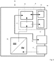
- Figure 3 describes a variant of the field device described above, which represents a head station in relation to the automation environment.
- This does not include a functional module 8, but in addition a network interface 16 and a network connection 17.
- a network voltage of 220 volts is applied to a voltage converter 18 via the network connection 17, which converts the applied AC voltage of 220 volts, or 110 volts in the USA converts a direct voltage of 48 volts.
- This 48 volt DC voltage is applied to the voltage supply 11 of the computing unit 10 and is also fed into the electrical interface 12, which is also provided in the base module 9 which is already known and is also present here.
- processing unit 10 communicates here with the network interface 16 and receives requests from an external network, for example the Internet, and sends data packets out of the internal network.
- an external network for example the Internet
- FIG Figure 4 shows another aspect of the invention in a detailed section of a cross section through the housing 1.
- the base plate for its part, is connected to the square profile 4 of the housing 1 via heat transfers 21, here designed as screws, so that in addition the heat on the base plate 2 can be passed on to the square profile.
- the affected housing parts 2 and 4 are made of a thermally conductive material.
- Figure 5 shows an alternative to the previous one Figure 4 , in which the microprocessor 19 mounted on a printed circuit board 20 makes direct contact with the square profile 4, more precisely on the back of the longitudinal grooves 5, via a heat transfer 21 in the form of a thermally conductive plate.
- the heat is introduced directly into the square profile 4 and distributed there so that a large surface is available for dissipation.
- the heat can also be dissipated into the cover plate 3 and / or the base plate 2 via the mounting screws in the opposite direction.
- a modular field device is thus described above which, due to the design of its housing in a polygonal profile, has a high degree of modularization and enables largely standardized components in the form of a base module and variable function modules to be used.
Landscapes
- Engineering & Computer Science (AREA)
- Physics & Mathematics (AREA)
- General Physics & Mathematics (AREA)
- Microelectronics & Electronic Packaging (AREA)
- Theoretical Computer Science (AREA)
- Automation & Control Theory (AREA)
- Human Computer Interaction (AREA)
- General Engineering & Computer Science (AREA)
- Signal Processing (AREA)
- Computer Hardware Design (AREA)
- Power Engineering (AREA)
- Computer Networks & Wireless Communication (AREA)
- Cooling Or The Like Of Electrical Apparatus (AREA)
- Programmable Controllers (AREA)
- Casings For Electric Apparatus (AREA)
Priority Applications (1)
| Application Number | Priority Date | Filing Date | Title |
|---|---|---|---|
| PL18732642T PL3632196T3 (pl) | 2017-05-31 | 2018-05-17 | Zbudowane modułowo urządzenie polowe |
Applications Claiming Priority (2)
| Application Number | Priority Date | Filing Date | Title |
|---|---|---|---|
| DE102017111998.1A DE102017111998A1 (de) | 2017-05-31 | 2017-05-31 | Modular aufgebautes feldgerät |
| PCT/DE2018/100478 WO2018219400A1 (de) | 2017-05-31 | 2018-05-17 | Modular aufgebautes feldgerät |
Publications (2)
| Publication Number | Publication Date |
|---|---|
| EP3632196A1 EP3632196A1 (de) | 2020-04-08 |
| EP3632196B1 true EP3632196B1 (de) | 2021-04-21 |
Family
ID=62684559
Family Applications (1)
| Application Number | Title | Priority Date | Filing Date |
|---|---|---|---|
| EP18732642.6A Active EP3632196B1 (de) | 2017-05-31 | 2018-05-17 | Modular aufgebautes feldgerät |
Country Status (8)
| Country | Link |
|---|---|
| US (1) | US10921867B2 (pl) |
| EP (1) | EP3632196B1 (pl) |
| CN (1) | CN110651536A (pl) |
| DE (2) | DE102017111998A1 (pl) |
| ES (1) | ES2881181T3 (pl) |
| PL (1) | PL3632196T3 (pl) |
| PT (1) | PT3632196T (pl) |
| WO (1) | WO2018219400A1 (pl) |
Families Citing this family (2)
| Publication number | Priority date | Publication date | Assignee | Title |
|---|---|---|---|---|
| DE102018133647A1 (de) * | 2018-12-28 | 2020-07-02 | Beckhoff Automation Gmbh | Schaltschranksystem aus Basismodul und Funktionsmodulen sowie Funktionsmodul |
| US11202378B1 (en) * | 2020-07-30 | 2021-12-14 | Baidu Usa Llc | Modular infrastructure for compute and storage clusters |
Family Cites Families (26)
| Publication number | Priority date | Publication date | Assignee | Title |
|---|---|---|---|---|
| US4656559A (en) * | 1984-05-10 | 1987-04-07 | Ultima Electronics Ltd. | Holder and heat sink for electronic components |
| DE29716575U1 (de) | 1997-09-15 | 1997-11-13 | Siemens AG, 80333 München | Feldbusgesteuertes Automatisierungsgerät |
| DE29906804U1 (de) * | 1999-04-19 | 1999-07-08 | Stegmann Max Antriebstech | Positionier- und Stellantrieb |
| DE20003279U1 (de) * | 2000-02-23 | 2000-04-20 | Berthold Sichert GmbH, 12277 Berlin | Verteilerschrank |
| US7844365B2 (en) * | 2000-05-12 | 2010-11-30 | Rosemount Inc. | Field-mounted process device |
| EP1454218A1 (en) * | 2002-04-06 | 2004-09-08 | Zalman Tech Co., Ltd. | Chipset cooling device of video graphic adapter card |
| KR20050059262A (ko) * | 2002-10-14 | 2005-06-17 | 지멘스 악티엔게젤샤프트 | 스위칭 모듈, 스위칭 모듈 및 압력 스트립을 장착하기 위한방법 |
| EP1929383A1 (en) * | 2005-07-20 | 2008-06-11 | Rosemount, Inc. | Field device with power over ethernet |
| US8036231B2 (en) * | 2005-08-09 | 2011-10-11 | Adc Telecommunications, Inc. | Wall-mountable connector |
| DE102006019555B3 (de) | 2006-04-27 | 2007-11-22 | Abb Patent Gmbh | Messumformer |
| WO2007140467A2 (en) * | 2006-05-31 | 2007-12-06 | Akros Silicon, Inc. | Ethernet module |
| DE202009005875U1 (de) * | 2009-04-17 | 2009-10-08 | Heliocentris Energiesysteme Gmbh | Modulares Brennstoffzellen-System |
| US8674823B1 (en) * | 2009-05-12 | 2014-03-18 | Plug ID, LLC. | Power management system |
| US20120224337A1 (en) * | 2011-03-04 | 2012-09-06 | Bodine Joel Cristopher | Compact communication system |
| CN202111966U (zh) * | 2011-06-23 | 2012-01-11 | 西安市伟创科技有限责任公司 | 上架式镁铝型材机箱 |
| US9727511B2 (en) * | 2011-12-30 | 2017-08-08 | Bedrock Automation Platforms Inc. | Input/output module with multi-channel switching capability |
| DE202012101067U1 (de) * | 2012-03-26 | 2012-07-10 | Ferrofacta Gmbh | Kompensationseinrichtung für thermische Ausdehnung |
| DE102012006787A1 (de) * | 2012-04-04 | 2013-10-10 | Inter Control Hermann Köhler Elektrik GmbH & Co. KG | Erweiterbares Gehäuse für elektrische Bauteile, Zwischengehäuseteil für das erweiterbare Gehäuse, sowie Verfahren zur Herstellung und zur Montage des Gehäuses |
| US9860071B2 (en) * | 2013-03-01 | 2018-01-02 | Computer Performance, Inc. | Power over ethernet injector |
| US9408335B2 (en) * | 2013-06-28 | 2016-08-02 | Cisco Technology, Inc. | ICM optimization and standardization for automation |
| DE102014109783A1 (de) * | 2014-07-11 | 2016-01-14 | Pilz Gmbh & Co. Kg | Automatisierungsgerät mit Montagehilfe |
| KR101575268B1 (ko) * | 2014-09-30 | 2015-12-07 | 현대오트론 주식회사 | 고정 부재를 이용한 차량의 전자 제어 장치 및 그 제조 방법 |
| CN106537721B (zh) * | 2015-03-18 | 2018-05-15 | 艾欧塔工程有限公司 | 以太网供电应急照明系统和检测其链路段电力丢失的方法 |
| DE102015107306A1 (de) * | 2015-05-11 | 2016-11-17 | Endress + Hauser Gmbh + Co. Kg | Feldgerät zum Einsatz in der Prozessautomatisierung |
| US11706895B2 (en) * | 2016-07-19 | 2023-07-18 | Pure Storage, Inc. | Independent scaling of compute resources and storage resources in a storage system |
| US10289572B2 (en) * | 2016-10-14 | 2019-05-14 | General Electric Company | Industrial control adjacent input-output modules and methods thereof |
-
2017
- 2017-05-31 DE DE102017111998.1A patent/DE102017111998A1/de not_active Withdrawn
-
2018
- 2018-05-17 US US16/605,532 patent/US10921867B2/en not_active Expired - Fee Related
- 2018-05-17 ES ES18732642T patent/ES2881181T3/es active Active
- 2018-05-17 PL PL18732642T patent/PL3632196T3/pl unknown
- 2018-05-17 CN CN201880032055.7A patent/CN110651536A/zh active Pending
- 2018-05-17 WO PCT/DE2018/100478 patent/WO2018219400A1/de not_active Ceased
- 2018-05-17 EP EP18732642.6A patent/EP3632196B1/de active Active
- 2018-05-17 PT PT187326426T patent/PT3632196T/pt unknown
- 2018-05-17 DE DE112018002818.6T patent/DE112018002818A5/de not_active Withdrawn
Non-Patent Citations (1)
| Title |
|---|
| None * |
Also Published As
| Publication number | Publication date |
|---|---|
| PL3632196T3 (pl) | 2021-11-15 |
| US10921867B2 (en) | 2021-02-16 |
| CN110651536A (zh) | 2020-01-03 |
| ES2881181T3 (es) | 2021-11-29 |
| US20200125147A1 (en) | 2020-04-23 |
| EP3632196A1 (de) | 2020-04-08 |
| WO2018219400A1 (de) | 2018-12-06 |
| DE102017111998A1 (de) | 2018-12-06 |
| DE112018002818A5 (de) | 2020-03-05 |
| PT3632196T (pt) | 2021-07-12 |
Similar Documents
| Publication | Publication Date | Title |
|---|---|---|
| EP1175133B1 (de) | Geräteverbund mit mindestens zwei Roboter und einem Steuerschrank | |
| DE102017201410B3 (de) | Kühlvorrichtung und Robotersteuervorrichtung mit einer solchen Kühlvorrichtung | |
| DE10204866A1 (de) | Wärmeableitmodul | |
| DE3787748T2 (de) | Mittel zum Montieren eines Gehäusemoduls an einer Schalttafel. | |
| EP3884741B1 (de) | Schaltschranksystem aus basismodul und funktionsmodulen sowie funktionsmodul | |
| EP2699066B1 (de) | Verriegelungselement zur Verriegelung eines Deckblechs an einer Modulschiene | |
| DE102009015542A1 (de) | Bidirektionale Kabelschuhverbindung und Verfahren | |
| AT399075B (de) | Rückwand für ein gehäuse zur aufnahme elektrischer baugruppen | |
| DE112014005950T5 (de) | Elektronische Vorrichtung mit Kühlfunktion | |
| EP3214670B1 (de) | Batteriemodul für eine mehrzahl derartiger batteriemodule aufweisende batterieanordnungen | |
| WO2018219400A1 (de) | Modular aufgebautes feldgerät | |
| DE102009057273A1 (de) | Elektronische Baugruppe | |
| EP3096593B1 (de) | Geräteträgertafel eines satelliten | |
| WO2008083878A1 (de) | Fixierungselement für leiterplatten | |
| EP3698611B1 (de) | Lüfterloses kühlsystem | |
| EP2590493B1 (de) | Frequenzumrichter | |
| DE102014010682A1 (de) | Temperaturmessanordnung für eine Schaltanlage | |
| DE102015105407A1 (de) | Verfahren, Netzwerk und Vorrichtung zur Steuerung und/oder Versorgung zumindest einer Maschine | |
| EP3748227A1 (de) | Tunnelleuchte | |
| DE102010044358A1 (de) | Schraubsystem und Verfahren zur Herstellung eines Schraubsystems | |
| DE102020132650B4 (de) | Elektronikgehäuse für einen hub zum ansteuern mehrerer aktoren | |
| DE3914539C2 (pl) | ||
| DE2608125B2 (de) | Einsatz für Gestelle der elektrischen Übertragungstechnik | |
| WO2015189276A1 (de) | Anlagenmodul mit abnehmbarem gehäuseteil | |
| EP2031472B2 (de) | Vorrichtung zum Betrieb einer Maschine |
Legal Events
| Date | Code | Title | Description |
|---|---|---|---|
| STAA | Information on the status of an ep patent application or granted ep patent |
Free format text: STATUS: UNKNOWN |
|
| STAA | Information on the status of an ep patent application or granted ep patent |
Free format text: STATUS: THE INTERNATIONAL PUBLICATION HAS BEEN MADE |
|
| PUAI | Public reference made under article 153(3) epc to a published international application that has entered the european phase |
Free format text: ORIGINAL CODE: 0009012 |
|
| STAA | Information on the status of an ep patent application or granted ep patent |
Free format text: STATUS: REQUEST FOR EXAMINATION WAS MADE |
|
| 17P | Request for examination filed |
Effective date: 20191009 |
|
| AK | Designated contracting states |
Kind code of ref document: A1 Designated state(s): AL AT BE BG CH CY CZ DE DK EE ES FI FR GB GR HR HU IE IS IT LI LT LU LV MC MK MT NL NO PL PT RO RS SE SI SK SM TR |
|
| AX | Request for extension of the european patent |
Extension state: BA ME |
|
| DAV | Request for validation of the european patent (deleted) | ||
| DAX | Request for extension of the european patent (deleted) | ||
| GRAP | Despatch of communication of intention to grant a patent |
Free format text: ORIGINAL CODE: EPIDOSNIGR1 |
|
| STAA | Information on the status of an ep patent application or granted ep patent |
Free format text: STATUS: GRANT OF PATENT IS INTENDED |
|
| INTG | Intention to grant announced |
Effective date: 20201119 |
|
| RIN1 | Information on inventor provided before grant (corrected) |
Inventor name: BIHLMAIER, ANDREAS Inventor name: LIEDKE, JENS Inventor name: MINTENBECK, JULIEN |
|
| GRAJ | Information related to disapproval of communication of intention to grant by the applicant or resumption of examination proceedings by the epo deleted |
Free format text: ORIGINAL CODE: EPIDOSDIGR1 |
|
| STAA | Information on the status of an ep patent application or granted ep patent |
Free format text: STATUS: REQUEST FOR EXAMINATION WAS MADE |
|
| GRAP | Despatch of communication of intention to grant a patent |
Free format text: ORIGINAL CODE: EPIDOSNIGR1 |
|
| STAA | Information on the status of an ep patent application or granted ep patent |
Free format text: STATUS: GRANT OF PATENT IS INTENDED |
|
| INTC | Intention to grant announced (deleted) | ||
| RIC1 | Information provided on ipc code assigned before grant |
Ipc: G01D 21/00 20060101ALI20210203BHEP Ipc: H05K 7/14 20060101AFI20210203BHEP Ipc: G01D 11/24 20060101ALI20210203BHEP |
|
| GRAS | Grant fee paid |
Free format text: ORIGINAL CODE: EPIDOSNIGR3 |
|
| GRAA | (expected) grant |
Free format text: ORIGINAL CODE: 0009210 |
|
| STAA | Information on the status of an ep patent application or granted ep patent |
Free format text: STATUS: THE PATENT HAS BEEN GRANTED |
|
| INTG | Intention to grant announced |
Effective date: 20210301 |
|
| AK | Designated contracting states |
Kind code of ref document: B1 Designated state(s): AL AT BE BG CH CY CZ DE DK EE ES FI FR GB GR HR HU IE IS IT LI LT LU LV MC MK MT NL NO PL PT RO RS SE SI SK SM TR |
|
| REG | Reference to a national code |
Ref country code: GB Ref legal event code: FG4D Free format text: NOT ENGLISH |
|
| REG | Reference to a national code |
Ref country code: CH Ref legal event code: EP |
|
| REG | Reference to a national code |
Ref country code: DE Ref legal event code: R096 Ref document number: 502018004928 Country of ref document: DE Ref country code: IE Ref legal event code: FG4D Free format text: LANGUAGE OF EP DOCUMENT: GERMAN |
|
| REG | Reference to a national code |
Ref country code: AT Ref legal event code: REF Ref document number: 1386026 Country of ref document: AT Kind code of ref document: T Effective date: 20210515 |
|
| REG | Reference to a national code |
Ref country code: PT Ref legal event code: SC4A Ref document number: 3632196 Country of ref document: PT Date of ref document: 20210712 Kind code of ref document: T Free format text: AVAILABILITY OF NATIONAL TRANSLATION Effective date: 20210705 |
|
| REG | Reference to a national code |
Ref country code: LT Ref legal event code: MG9D |
|
| PGFP | Annual fee paid to national office [announced via postgrant information from national office to epo] |
Ref country code: ES Payment date: 20210622 Year of fee payment: 4 |
|
| REG | Reference to a national code |
Ref country code: NL Ref legal event code: MP Effective date: 20210421 |
|
| PG25 | Lapsed in a contracting state [announced via postgrant information from national office to epo] |
Ref country code: NL Free format text: LAPSE BECAUSE OF FAILURE TO SUBMIT A TRANSLATION OF THE DESCRIPTION OR TO PAY THE FEE WITHIN THE PRESCRIBED TIME-LIMIT Effective date: 20210421 Ref country code: BG Free format text: LAPSE BECAUSE OF FAILURE TO SUBMIT A TRANSLATION OF THE DESCRIPTION OR TO PAY THE FEE WITHIN THE PRESCRIBED TIME-LIMIT Effective date: 20210721 Ref country code: FI Free format text: LAPSE BECAUSE OF FAILURE TO SUBMIT A TRANSLATION OF THE DESCRIPTION OR TO PAY THE FEE WITHIN THE PRESCRIBED TIME-LIMIT Effective date: 20210421 Ref country code: LT Free format text: LAPSE BECAUSE OF FAILURE TO SUBMIT A TRANSLATION OF THE DESCRIPTION OR TO PAY THE FEE WITHIN THE PRESCRIBED TIME-LIMIT Effective date: 20210421 Ref country code: HR Free format text: LAPSE BECAUSE OF FAILURE TO SUBMIT A TRANSLATION OF THE DESCRIPTION OR TO PAY THE FEE WITHIN THE PRESCRIBED TIME-LIMIT Effective date: 20210421 |
|
| PGFP | Annual fee paid to national office [announced via postgrant information from national office to epo] |
Ref country code: FR Payment date: 20210719 Year of fee payment: 4 Ref country code: CZ Payment date: 20210622 Year of fee payment: 4 |
|
| REG | Reference to a national code |
Ref country code: ES Ref legal event code: FG2A Ref document number: 2881181 Country of ref document: ES Kind code of ref document: T3 Effective date: 20211129 |
|
| PG25 | Lapsed in a contracting state [announced via postgrant information from national office to epo] |
Ref country code: GR Free format text: LAPSE BECAUSE OF FAILURE TO SUBMIT A TRANSLATION OF THE DESCRIPTION OR TO PAY THE FEE WITHIN THE PRESCRIBED TIME-LIMIT Effective date: 20210722 Ref country code: IS Free format text: LAPSE BECAUSE OF FAILURE TO SUBMIT A TRANSLATION OF THE DESCRIPTION OR TO PAY THE FEE WITHIN THE PRESCRIBED TIME-LIMIT Effective date: 20210821 Ref country code: LV Free format text: LAPSE BECAUSE OF FAILURE TO SUBMIT A TRANSLATION OF THE DESCRIPTION OR TO PAY THE FEE WITHIN THE PRESCRIBED TIME-LIMIT Effective date: 20210421 Ref country code: NO Free format text: LAPSE BECAUSE OF FAILURE TO SUBMIT A TRANSLATION OF THE DESCRIPTION OR TO PAY THE FEE WITHIN THE PRESCRIBED TIME-LIMIT Effective date: 20210721 Ref country code: SE Free format text: LAPSE BECAUSE OF FAILURE TO SUBMIT A TRANSLATION OF THE DESCRIPTION OR TO PAY THE FEE WITHIN THE PRESCRIBED TIME-LIMIT Effective date: 20210421 Ref country code: RS Free format text: LAPSE BECAUSE OF FAILURE TO SUBMIT A TRANSLATION OF THE DESCRIPTION OR TO PAY THE FEE WITHIN THE PRESCRIBED TIME-LIMIT Effective date: 20210421 |
|
| PGFP | Annual fee paid to national office [announced via postgrant information from national office to epo] |
Ref country code: DE Payment date: 20210713 Year of fee payment: 4 Ref country code: CH Payment date: 20210719 Year of fee payment: 4 |
|
| PGFP | Annual fee paid to national office [announced via postgrant information from national office to epo] |
Ref country code: PT Payment date: 20210708 Year of fee payment: 4 |
|
| REG | Reference to a national code |
Ref country code: DE Ref legal event code: R097 Ref document number: 502018004928 Country of ref document: DE |
|
| PG25 | Lapsed in a contracting state [announced via postgrant information from national office to epo] |
Ref country code: EE Free format text: LAPSE BECAUSE OF FAILURE TO SUBMIT A TRANSLATION OF THE DESCRIPTION OR TO PAY THE FEE WITHIN THE PRESCRIBED TIME-LIMIT Effective date: 20210421 Ref country code: SK Free format text: LAPSE BECAUSE OF FAILURE TO SUBMIT A TRANSLATION OF THE DESCRIPTION OR TO PAY THE FEE WITHIN THE PRESCRIBED TIME-LIMIT Effective date: 20210421 Ref country code: DK Free format text: LAPSE BECAUSE OF FAILURE TO SUBMIT A TRANSLATION OF THE DESCRIPTION OR TO PAY THE FEE WITHIN THE PRESCRIBED TIME-LIMIT Effective date: 20210421 Ref country code: LU Free format text: LAPSE BECAUSE OF NON-PAYMENT OF DUE FEES Effective date: 20210517 Ref country code: MC Free format text: LAPSE BECAUSE OF FAILURE TO SUBMIT A TRANSLATION OF THE DESCRIPTION OR TO PAY THE FEE WITHIN THE PRESCRIBED TIME-LIMIT Effective date: 20210421 Ref country code: SM Free format text: LAPSE BECAUSE OF FAILURE TO SUBMIT A TRANSLATION OF THE DESCRIPTION OR TO PAY THE FEE WITHIN THE PRESCRIBED TIME-LIMIT Effective date: 20210421 Ref country code: RO Free format text: LAPSE BECAUSE OF FAILURE TO SUBMIT A TRANSLATION OF THE DESCRIPTION OR TO PAY THE FEE WITHIN THE PRESCRIBED TIME-LIMIT Effective date: 20210421 |
|
| REG | Reference to a national code |
Ref country code: BE Ref legal event code: MM Effective date: 20210531 |
|
| PLBE | No opposition filed within time limit |
Free format text: ORIGINAL CODE: 0009261 |
|
| STAA | Information on the status of an ep patent application or granted ep patent |
Free format text: STATUS: NO OPPOSITION FILED WITHIN TIME LIMIT |
|
| 26N | No opposition filed |
Effective date: 20220124 |
|
| PG25 | Lapsed in a contracting state [announced via postgrant information from national office to epo] |
Ref country code: IE Free format text: LAPSE BECAUSE OF NON-PAYMENT OF DUE FEES Effective date: 20210517 |
|
| PG25 | Lapsed in a contracting state [announced via postgrant information from national office to epo] |
Ref country code: IS Free format text: LAPSE BECAUSE OF FAILURE TO SUBMIT A TRANSLATION OF THE DESCRIPTION OR TO PAY THE FEE WITHIN THE PRESCRIBED TIME-LIMIT Effective date: 20210821 Ref country code: AL Free format text: LAPSE BECAUSE OF FAILURE TO SUBMIT A TRANSLATION OF THE DESCRIPTION OR TO PAY THE FEE WITHIN THE PRESCRIBED TIME-LIMIT Effective date: 20210421 |
|
| PGFP | Annual fee paid to national office [announced via postgrant information from national office to epo] |
Ref country code: IT Payment date: 20210531 Year of fee payment: 4 |
|
| PG25 | Lapsed in a contracting state [announced via postgrant information from national office to epo] |
Ref country code: BE Free format text: LAPSE BECAUSE OF NON-PAYMENT OF DUE FEES Effective date: 20210531 |
|
| PGFP | Annual fee paid to national office [announced via postgrant information from national office to epo] |
Ref country code: PL Payment date: 20210622 Year of fee payment: 4 |
|
| REG | Reference to a national code |
Ref country code: DE Ref legal event code: R119 Ref document number: 502018004928 Country of ref document: DE |
|
| REG | Reference to a national code |
Ref country code: CH Ref legal event code: PL |
|
| GBPC | Gb: european patent ceased through non-payment of renewal fee |
Effective date: 20220517 |
|
| PG25 | Lapsed in a contracting state [announced via postgrant information from national office to epo] |
Ref country code: LI Free format text: LAPSE BECAUSE OF NON-PAYMENT OF DUE FEES Effective date: 20220531 Ref country code: CZ Free format text: LAPSE BECAUSE OF NON-PAYMENT OF DUE FEES Effective date: 20220517 Ref country code: CH Free format text: LAPSE BECAUSE OF NON-PAYMENT OF DUE FEES Effective date: 20220531 |
|
| PG25 | Lapsed in a contracting state [announced via postgrant information from national office to epo] |
Ref country code: PT Free format text: LAPSE BECAUSE OF NON-PAYMENT OF DUE FEES Effective date: 20230217 Ref country code: FR Free format text: LAPSE BECAUSE OF NON-PAYMENT OF DUE FEES Effective date: 20220531 |
|
| PG25 | Lapsed in a contracting state [announced via postgrant information from national office to epo] |
Ref country code: GB Free format text: LAPSE BECAUSE OF NON-PAYMENT OF DUE FEES Effective date: 20220517 Ref country code: DE Free format text: LAPSE BECAUSE OF NON-PAYMENT OF DUE FEES Effective date: 20221201 |
|
| REG | Reference to a national code |
Ref country code: ES Ref legal event code: FD2A Effective date: 20230626 |
|
| PG25 | Lapsed in a contracting state [announced via postgrant information from national office to epo] |
Ref country code: CY Free format text: LAPSE BECAUSE OF FAILURE TO SUBMIT A TRANSLATION OF THE DESCRIPTION OR TO PAY THE FEE WITHIN THE PRESCRIBED TIME-LIMIT Effective date: 20210421 |
|
| PG25 | Lapsed in a contracting state [announced via postgrant information from national office to epo] |
Ref country code: IT Free format text: LAPSE BECAUSE OF NON-PAYMENT OF DUE FEES Effective date: 20220517 Ref country code: HU Free format text: LAPSE BECAUSE OF FAILURE TO SUBMIT A TRANSLATION OF THE DESCRIPTION OR TO PAY THE FEE WITHIN THE PRESCRIBED TIME-LIMIT; INVALID AB INITIO Effective date: 20180517 Ref country code: ES Free format text: LAPSE BECAUSE OF NON-PAYMENT OF DUE FEES Effective date: 20220518 |
|
| PG25 | Lapsed in a contracting state [announced via postgrant information from national office to epo] |
Ref country code: MK Free format text: LAPSE BECAUSE OF FAILURE TO SUBMIT A TRANSLATION OF THE DESCRIPTION OR TO PAY THE FEE WITHIN THE PRESCRIBED TIME-LIMIT Effective date: 20210421 |
|
| PG25 | Lapsed in a contracting state [announced via postgrant information from national office to epo] |
Ref country code: PL Free format text: LAPSE BECAUSE OF NON-PAYMENT OF DUE FEES Effective date: 20220517 |
|
| PG25 | Lapsed in a contracting state [announced via postgrant information from national office to epo] |
Ref country code: TR Free format text: LAPSE BECAUSE OF FAILURE TO SUBMIT A TRANSLATION OF THE DESCRIPTION OR TO PAY THE FEE WITHIN THE PRESCRIBED TIME-LIMIT Effective date: 20210421 |
|
| REG | Reference to a national code |
Ref country code: AT Ref legal event code: MM01 Ref document number: 1386026 Country of ref document: AT Kind code of ref document: T Effective date: 20230517 |
|
| PG25 | Lapsed in a contracting state [announced via postgrant information from national office to epo] |
Ref country code: AT Free format text: LAPSE BECAUSE OF NON-PAYMENT OF DUE FEES Effective date: 20230517 |
|
| PG25 | Lapsed in a contracting state [announced via postgrant information from national office to epo] |
Ref country code: AT Free format text: LAPSE BECAUSE OF NON-PAYMENT OF DUE FEES Effective date: 20230517 |
|
| PG25 | Lapsed in a contracting state [announced via postgrant information from national office to epo] |
Ref country code: MT Free format text: LAPSE BECAUSE OF FAILURE TO SUBMIT A TRANSLATION OF THE DESCRIPTION OR TO PAY THE FEE WITHIN THE PRESCRIBED TIME-LIMIT Effective date: 20210421 |
|
| PGFP | Annual fee paid to national office [announced via postgrant information from national office to epo] |
Ref country code: AT Payment date: 20260410 Year of fee payment: 5 |