EP3632200B1 - Système de battage pour moissonneuse-batteuse - Google Patents
Système de battage pour moissonneuse-batteuse Download PDFInfo
- Publication number
- EP3632200B1 EP3632200B1 EP18198420.4A EP18198420A EP3632200B1 EP 3632200 B1 EP3632200 B1 EP 3632200B1 EP 18198420 A EP18198420 A EP 18198420A EP 3632200 B1 EP3632200 B1 EP 3632200B1
- Authority
- EP
- European Patent Office
- Prior art keywords
- vanes
- transition device
- vane
- cone
- crop material
- Prior art date
- Legal status (The legal status is an assumption and is not a legal conclusion. Google has not performed a legal analysis and makes no representation as to the accuracy of the status listed.)
- Active
Links
Images


Classifications
-
- A—HUMAN NECESSITIES
- A01—AGRICULTURE; FORESTRY; ANIMAL HUSBANDRY; HUNTING; TRAPPING; FISHING
- A01F—PROCESSING OF HARVESTED PRODUCE; HAY OR STRAW PRESSES; DEVICES FOR STORING AGRICULTURAL OR HORTICULTURAL PRODUCE
- A01F12/00—Parts or details of threshing apparatus
- A01F12/10—Feeders
-
- A—HUMAN NECESSITIES
- A01—AGRICULTURE; FORESTRY; ANIMAL HUSBANDRY; HUNTING; TRAPPING; FISHING
- A01F—PROCESSING OF HARVESTED PRODUCE; HAY OR STRAW PRESSES; DEVICES FOR STORING AGRICULTURAL OR HORTICULTURAL PRODUCE
- A01F7/00—Threshing apparatus
- A01F7/02—Threshing apparatus with rotating tools
- A01F7/06—Threshing apparatus with rotating tools with axles in line with the feeding direction ; Axial threshing machines
- A01F7/067—Threshing apparatus with rotating tools with axles in line with the feeding direction ; Axial threshing machines with material-flow influencing means
Definitions
- the present invention pertains to an agricultural combine or harvester and, more specifically, to a threshing system with a transition cone.
- an agricultural harvester known as a "combine” is historically termed such because it combines multiple harvesting functions with a single harvesting unit, such as picking, threshing, separating and cleaning.
- a combine includes a header, which removes the crop from a field, and a feeder housing which transports the crop matter into a rotary threshing and separating system.
- the rotary threshing and separating system includes one or more rotors which extends axially (front to rear) or transversely within the body of the combine, and which is partially or fully surrounded by a perforated concave.
- the crop material is threshed and separated by the rotation of the rotor within the concave.
- Coarser non-grain crop material such as stalks and leaves are transported to the rear of the combine and discharged back to the field.
- the separated grain, together with some finer non-grain crop material such as chaff, dust, straw, and other crop residue are discharged through the concaves and fall onto a grain pan where they are transported to a cleaning system.
- a transition cone is positioned between the feeder housing and the concave.
- the transition cone directs the gathered crop material toward the rotor cage while narrowing, acting as a funnel for the gathered crop material toward the rotor.
- FIG. 1 A prior art rotary threshing and separating system is shown in FIG. 1 .
- a prior art rotor assembly 72 which can be included in a threshing and separating system is shown and generally includes a rotor 74 defining a longitudinal axis A1, a concave 76 partially surrounding the rotor 74 and having perforations formed through, and a transition cone 80 connected to the concave 76 at a connection point 82 and defining an infeed to the rotor 74 from, for example, a feeder housing.
- the transition cone 80 has a frusto-conical shape defined about the longitudinal axis A1 that ends abruptly at the connection point 82 between the transition cone 80 and the rotor cage 76.
- the transition cone 80 has a tapering diameter along its length so that as the transition cone 80 approaches the connection point 82, the transition cone 80 narrows.
- the transition cone 80 includes a series of vanes 120 disposed along its inner surface for directing the crop material toward the reduced clearance W1 between the rotor 74 and the connection point 82.
- the vanes 120 guide the crop material as it travels along a conical spiral trajectory within the cone 80. It should be understood that the cone 80 remains fixed in position as the rotor 74 rotates about its axis to deliver crop material through the cone 80 and the concave 76.
- Each vane 120 has a conical spiral shape, and extends from the inlet of the cone 80 to the outlet of the cone 80.
- the vanes 88 are uniformly spaced apart in a radial manner about the longitudinal axis A1, and are arranged at an equal pitch about the longitudinal axis A1.
- the first ends of the vanes 120 at the inlet end of the cone 80 are uniformly spaced apart about the inlet end of the cone 80, and, the second ends of the vanes 120 at the outlet end of the cone 80 are uniformly spaced apart about the outlet end of the cone 80.
- Such an arrangement of vanes is also disclosed in U.S. Patent No. 6,830,512 to Tanis, for example (see vanes 61), and FIG. 3 of U.S. Patent No. 4,148,323 .
- the incoming crop material initially travels in a linear fashion up the feeder housing (see item 20 of U.S. Patent Application Publ. No. 20170013781 to Flickinger ).
- the majority of crop material then enters the inlet end of the transition cone 80 over a defined arc of about 180 degrees, which is significantly less than the 360 degree circumference of the inlet end of the cone 80.
- the crop material transitions from a linear motion to a rotary motion as it enters the cone 80 and travels between adjacent vanes120 of the cone 80.
- the vanes 120 compress the crop material as it transitions from a larger circumferential area at the inlet of the cone 80 to a smaller circumferential area at the outlet of the cone 80.
- the compressed crop material ultimately exits the cone 80 over a 180 degree exit area and enters the threshing chamber.
- the rotary threshing system can have difficulty in managing the compressed crop material in an efficient manner.
- US2017/105350 A1 discloses a transition cone for a threshing system of an agricultural harvesting machine that has an inner surface with a tapering inner circumference between a wider upstream end and a narrower downstream end, and a plurality of vanes in the transition cone. Each vane extends between the upstream end and the downstream end and at least partly around the tapering inner circumference. Each vane includes an upstanding segment extending away from the inner surface, and a base segment extending from the upstanding segment along the inner surface on the downstream side of the upstanding segment. The base segment has a thicker proximal region adjacent the upstanding segment and a thinner distal edge opposite thereto, with a curved exposed surface extending there between.
- a transition device for a threshing system for an agricultural harvester includes a body having an inlet end for receiving crop material from a feeder source, and an outlet end opposite the inlet end for distributing crop material into a threshing space of the threshing system.
- a plurality of vanes are positioned on an interior facing surface of the body for guiding the crop material through the transition device.
- Each vane has a first end positioned either on or adjacent the inlet end of the body and a second end positioned either on or adjacent the outlet end of the body.
- An arc length defined between the first ends of two adjacent vanes of the plurality of vanes is less than or equal to an arc length defined between the second ends of the two adjacent vanes of the plurality of vanes, such that the crop material can expand between the two adjacent vanes upon travelling along a trajectory from the inlet end to the outlet end of the transition cone.
- radial and radially refer to a direction, dimension or orientation that is perpendicular to the center axis of the cone.
- the radius and diameter of a cone are considered “radial” dimensions.
- inward and inwardly refer to a direction, dimension or orientation that extends in a radial direction toward the center axis.
- outward and outwardly refer to a direction, dimension or orientation that extends in a radial direction away from the center axis.
- the transition cone 10 is configured for use with a rotor assembly, such as the rotor assembly 72 of FIG. 1 .
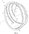
- the transition cone 10 of FIGs. 2 and 3 has a frusto-conical shape defined about the longitudinal axis A that ends abruptly at the connection point between the transition cone 10 and the rotor cage (such as cage 76 of FIG. 1 ).
- the transition cone 10 may be more generally referred to herein as a transition device since it can have either a frusto-conical or a cylindrical shape.
- the transition cone may also be referred to in the art as a cover of an infeed section.
- each vane 12 has a conical spiral shape, and extends continuously from the large-diameter inlet end 14 of the cone 10 to the small-diameter outlet end 16 of the cone 10.
- Each vane 12 includes a first end 18 (i.e., starting point) at the inlet end 14 of the cone 10, and a second end 20 (i.e., end point) at the outlet end 16 of the cone 10.
- the vanes 12 have an unequal pitch about the longitudinal axis A. In other words, no two vanes 12 have the same pitch.
- the pitch (or lead) of a vane is the distance along the axis of the cone 10 that is covered by one complete rotation of the vane. It should be understood that the length of the cone 10 is relatively short such that none of the vanes 12 rotate completely about the cone 10.
- the vane 12a having a first end 18 at the bottom of the inlet end 14 cone 10, has the longest pitch.
- the pitch of the vanes 12 decreases in the clockwise direction about the longitudinal axis A (as viewed in FIG. 2 ) such that the vane 12a has the longest pitch and the vane 12e has the shortest pitch.
- the first ends 18 of the vanes 12 are positioned along the inlet 14 of the cone 10 where the concentrated in-feed of crop material occurs.
- the first ends 18 of the vanes 12 are uniformly spaced apart about an arc length L of the circumference of the inlet 14.
- the arc length L is about 180 degrees, for example. It should be understood that the number of vanes 12 could vary, and, if so, the first ends 18 would be uniformly spaced apart by about 180/X degrees, where X equals the number of vanes.
- first ends 18 assumes that the rotor is rotating in a counterclockwise direction, as viewed in FIG. 2 . If the rotor were to rotate in a clockwise direction, then the first ends 18 would be concentrated in the circumference of the inlet 14 that is outside of arc length L.
- each vane 12 is selected such that the arc length L1 between the first ends 18 of two adjacent vanes 12 is equal to or less than the arc length L2 between the second ends 20 of those two adjacent vanes 12. Accordingly, the crop material travelling between those two vanes 12 is not compressed at the outlet of the cone 10, which would result in increased crop pressure and inefficient threshing of the crop material.
- the second ends 20 are uniformly spaced apart by about an arc length L2 of about 72 degrees about the circumference of the outlet 16 of the cone 10. If the number of vanes 12 vary, then the second ends 20 will be uniformly spaced apart by about 360/X degrees, where X equals the number of vanes.
- Each vane 12 is provided in the form of an L-shaped bracket (as viewed in cross-section), although, the cross-sectional shape of each vane 12 could vary.
- the vanes 12 may be a separate component that is mounted to the cone 10, or, alternatively, the vanes 12 could be integrated with the cone 10.
- a supplemental vane 19 is positioned between the vanes 12a and 12e.
- the vane 19 includes a first end 19a that is positioned adjacent the inlet 14 and a second end 19b that is spaced from the outlet 16.
- the incoming crop material initially travels in a linear fashion up the feeder housing (see item 20 of U.S. Patent Application Publ. No. 20170013781 to Flickinger ).
- the rotor draws the crop material into the inlet end of the transition cone 10 over the defined arc length L.
- the crop material transitions from a linear motion to a rotary motion as it enters the cone 10 and travels between adjacent vanes 12 of the cone 10.
- the crop material travelling between adjacent vanes 12 at the inlet end 14 of the cone 10 is less than the arc length L2 of the crop material travelling between those adjacent vanes 12 at the outlet end 16 of the cone 10, due to the geometry and position of the vanes 12, the crop material can expand as it travels between those adjacent vanes 12 and through the cone 10.
- the crop material ultimately exits the cone 10 over an exit area that is greater than 120 degrees. Because the crop material has not been compressed to any significant degree, the rotary threshing system has an easier time managing the crop material in an efficient manner, as compared with prior art threshing systems.
Landscapes
- Life Sciences & Earth Sciences (AREA)
- Environmental Sciences (AREA)
- Threshing Machine Elements (AREA)
Claims (14)
- Dispositif de transition (10) pour système de battage de moissonneuse agricole, le dispositif de transition (10) comprenant :un corps ayant une extrémité d'entrée (14) destinée à recevoir des matières récoltées d'une source d'alimentation, et une extrémité de sortie (16) opposée à l'extrémité d'entrée (14) destinée à distribuer des matières récoltées dans un espace de battage du système de battage ; etune pluralité d'aubes (12) positionnées sur une surface orientée vers l'intérieur du corps pour guider les matières récoltées à travers le dispositif de transition (10), chaque aube (12) ayant une première extrémité (18) positionnée soit sur, soit de manière adjacente à l'extrémité d'entrée (14) du corps et une deuxième extrémité (20) positionnée soit sur, soit de manière adjacente à l'extrémité de sortie (16) du corps, caractérisée en ce queune longueur d'arc [L1] entre les premières extrémités (18) des deux aubes adjacentes de la pluralité d'aubes est inférieure à ou égale à une longueur d'arc [L2] entre les deuxièmes extrémités (20) des deux aubes adjacentes (12) de la pluralité d'aubes, de sorte que les matières récoltées puissent s'étendre entre les deux aubes adjacentes lorsqu'elles se déplacent le long d'un trajet à partir de l'extrémité d'entrée (14) vers l'extrémité de sortie (16) du dispositif de transition (10).
- Dispositif de transition selon la revendication 1, dans lequel le corps a une forme tronconique ou une forme cylindrique.
- Dispositif de transition selon la revendication 1, dans lequel un diamètre de l'extrémité d'entrée (14) du corps est supérieur au diamètre de l'extrémité de sortie (16) du corps.
- Dispositif de transition selon l'une quelconque des revendications précédentes, dans lequel chaque aube (12) a une forme de spirale.
- Dispositif de transition selon l'une quelconque des revendications précédentes, dans lequel une inclinaison de chaque vanne (12) est différente.
- Dispositif de transition selon la revendication 5, dans lequel l'inclinaison des aubes (12) diminue successivement d'une aube de la pluralité d'aubes à une aube adjacente de la pluralité d'aubes.
- Dispositif de transition selon l'une quelconque des revendications précédentes, dans lequel les deuxièmes extrémités (20) des aubes sont espacées uniformément les unes des autres autour d'une circonférence de l'extrémité de sortie du corps.
- Dispositif de transition selon la revendication 7, dans lequel les premières extrémités (18) des aubes (12) ne sont pas espacées uniformément les unes des autres autour d'une circonférence de l'extrémité d'entrée (14) du corps.
- Dispositif de transition selon l'une quelconque des revendications précédentes, dans lequel les premières extrémités (18) des aubes (12) sont positionnées sur seulement un côté de l'extrémité d'entrée (14) du corps.
- Dispositif de transition selon la revendication 9, dans lequel les premières extrémités (18) des aubes (12) sont espacées uniformément les unes des autres autour d'un seul côté de l'extrémité d'entrée (14) du corps.
- Dispositif de transition selon l'une quelconque des revendications précédentes, dans lequel chaque aube (12) s'étend vers un axe longitudinal [A] du corps.
- Dispositif de transition selon l'une quelconque des revendications précédentes, dans lequel la première extrémité (18) de chaque aube (12) coupe l'extrémité d'entrée (14) du corps et la deuxième extrémité (20) de chaque aube (12) coupe l'extrémité de sortie (16) du corps.
- Dispositif de transition selon l'une quelconque des revendications précédentes, dans lequel chaque aube (12) s'étend en continu entre la première extrémité (18) et la deuxième extrémité (20) de l'aube.
- Dispositif de transition selon l'une quelconque des revendications précédentes, dans lequel chaque aube (12) est un support en L courbé.
Priority Applications (1)
| Application Number | Priority Date | Filing Date | Title |
|---|---|---|---|
| EP18198420.4A EP3632200B1 (fr) | 2018-10-03 | 2018-10-03 | Système de battage pour moissonneuse-batteuse |
Applications Claiming Priority (1)
| Application Number | Priority Date | Filing Date | Title |
|---|---|---|---|
| EP18198420.4A EP3632200B1 (fr) | 2018-10-03 | 2018-10-03 | Système de battage pour moissonneuse-batteuse |
Publications (2)
| Publication Number | Publication Date |
|---|---|
| EP3632200A1 EP3632200A1 (fr) | 2020-04-08 |
| EP3632200B1 true EP3632200B1 (fr) | 2021-07-14 |
Family
ID=63762264
Family Applications (1)
| Application Number | Title | Priority Date | Filing Date |
|---|---|---|---|
| EP18198420.4A Active EP3632200B1 (fr) | 2018-10-03 | 2018-10-03 | Système de battage pour moissonneuse-batteuse |
Country Status (1)
| Country | Link |
|---|---|
| EP (1) | EP3632200B1 (fr) |
Families Citing this family (2)
| Publication number | Priority date | Publication date | Assignee | Title |
|---|---|---|---|---|
| US12369529B2 (en) | 2021-12-30 | 2025-07-29 | Cnh Industrial America Llc | Variable cross-section vane for transition cone in combine harvester |
| DE102022123320A1 (de) * | 2022-09-13 | 2024-03-14 | Claas Selbstfahrende Erntemaschinen Gmbh | Selbstfahrender Mähdrescher |
Family Cites Families (5)
| Publication number | Priority date | Publication date | Assignee | Title |
|---|---|---|---|---|
| US4148323A (en) | 1977-11-21 | 1979-04-10 | International Harvester Company | Swept back impeller blade for axial flow rotor |
| US6830512B2 (en) | 2002-07-19 | 2004-12-14 | Cnh America Llc | Shroud for the infeed impeller of a rotary combine |
| US9807937B2 (en) | 2015-07-16 | 2017-11-07 | Cnh Industrial America Llc | Agricultural harvester with improved rotor transition geometry |
| US10159192B2 (en) * | 2015-09-17 | 2018-12-25 | Cone Guard, Llc | Transition cone liner for a farm combine |
| BR102016023877B1 (pt) * | 2015-10-16 | 2021-09-14 | Cnh Industrial America Llc | Colheitadeira agrícola |
-
2018
- 2018-10-03 EP EP18198420.4A patent/EP3632200B1/fr active Active
Also Published As
| Publication number | Publication date |
|---|---|
| EP3632200A1 (fr) | 2020-04-08 |
Similar Documents
| Publication | Publication Date | Title |
|---|---|---|
| US7749054B2 (en) | Modular separator element for a threshing system | |
| EP2298063B1 (fr) | Système de battage | |
| EP3266297B1 (fr) | Dissipateur de résidus de cultures | |
| US9456550B2 (en) | Threshing and separating device and combine harvester having the same | |
| US10051790B2 (en) | Vane arrangement in combine harvester processor | |
| US4062366A (en) | Rethresher | |
| US4178943A (en) | Rotor for an axial flow rotary separator | |
| US4192322A (en) | Axial flow separator with stepped threshing bar rotor | |
| US10420285B2 (en) | Transition device for a combine threshing system | |
| US20130137492A1 (en) | Throughput control adjustable vanes on agricultural combine harvester | |
| EP3632200B1 (fr) | Système de battage pour moissonneuse-batteuse | |
| EP2064937A1 (fr) | Partie avant de rotor entièrement conique et section de battage | |
| EP2055176A1 (fr) | Couvercle supérieur pour moissonneuse-batteuse rotative axiale disposant d'une transition conique | |
| US6296566B1 (en) | Infeed impeller for a rotary combine | |
| US9338945B2 (en) | Asymmetrical feed beater for a single rotor separator | |
| EP1872647B1 (fr) | Entrée chevron pour ventilateur à courants croisés | |
| US4136704A (en) | Rotor for a combine | |
| US4159023A (en) | Infeed means for axial flow combine | |
| US4422463A (en) | Rotor for an axial flow rotary separator | |
| AU6989100A (en) | Rotary threshing and separation unit | |
| US4164947A (en) | Rotor for an axial flow rotary separator | |
| US4397319A (en) | Cleaning device for harvesting machines | |
| US11147213B2 (en) | Threshing section of a combine | |
| US20220279726A1 (en) | Inlet cover for a cross flow fan | |
| EP3706547B1 (fr) | Interface cage de rotor-cône de transition pour moissonneuse agricole |
Legal Events
| Date | Code | Title | Description |
|---|---|---|---|
| PUAI | Public reference made under article 153(3) epc to a published international application that has entered the european phase |
Free format text: ORIGINAL CODE: 0009012 |
|
| STAA | Information on the status of an ep patent application or granted ep patent |
Free format text: STATUS: THE APPLICATION HAS BEEN PUBLISHED |
|
| AK | Designated contracting states |
Kind code of ref document: A1 Designated state(s): AL AT BE BG CH CY CZ DE DK EE ES FI FR GB GR HR HU IE IS IT LI LT LU LV MC MK MT NL NO PL PT RO RS SE SI SK SM TR |
|
| AX | Request for extension of the european patent |
Extension state: BA ME |
|
| STAA | Information on the status of an ep patent application or granted ep patent |
Free format text: STATUS: REQUEST FOR EXAMINATION WAS MADE |
|
| 17P | Request for examination filed |
Effective date: 20201008 |
|
| RBV | Designated contracting states (corrected) |
Designated state(s): AL AT BE BG CH CY CZ DE DK EE ES FI FR GB GR HR HU IE IS IT LI LT LU LV MC MK MT NL NO PL PT RO RS SE SI SK SM TR |
|
| GRAP | Despatch of communication of intention to grant a patent |
Free format text: ORIGINAL CODE: EPIDOSNIGR1 |
|
| STAA | Information on the status of an ep patent application or granted ep patent |
Free format text: STATUS: GRANT OF PATENT IS INTENDED |
|
| RIC1 | Information provided on ipc code assigned before grant |
Ipc: A01F 12/10 20060101ALI20210118BHEP Ipc: A01F 7/06 20060101AFI20210118BHEP |
|
| INTG | Intention to grant announced |
Effective date: 20210210 |
|
| GRAS | Grant fee paid |
Free format text: ORIGINAL CODE: EPIDOSNIGR3 |
|
| GRAA | (expected) grant |
Free format text: ORIGINAL CODE: 0009210 |
|
| STAA | Information on the status of an ep patent application or granted ep patent |
Free format text: STATUS: THE PATENT HAS BEEN GRANTED |
|
| AK | Designated contracting states |
Kind code of ref document: B1 Designated state(s): AL AT BE BG CH CY CZ DE DK EE ES FI FR GB GR HR HU IE IS IT LI LT LU LV MC MK MT NL NO PL PT RO RS SE SI SK SM TR |
|
| REG | Reference to a national code |
Ref country code: GB Ref legal event code: FG4D |
|
| REG | Reference to a national code |
Ref country code: DE Ref legal event code: R096 Ref document number: 602018020005 Country of ref document: DE |
|
| REG | Reference to a national code |
Ref country code: IE Ref legal event code: FG4D |
|
| REG | Reference to a national code |
Ref country code: AT Ref legal event code: REF Ref document number: 1409932 Country of ref document: AT Kind code of ref document: T Effective date: 20210815 |
|
| REG | Reference to a national code |
Ref country code: LT Ref legal event code: MG9D |
|
| REG | Reference to a national code |
Ref country code: NL Ref legal event code: MP Effective date: 20210714 |
|
| REG | Reference to a national code |
Ref country code: AT Ref legal event code: MK05 Ref document number: 1409932 Country of ref document: AT Kind code of ref document: T Effective date: 20210714 |
|
| PG25 | Lapsed in a contracting state [announced via postgrant information from national office to epo] |
Ref country code: NL Free format text: LAPSE BECAUSE OF FAILURE TO SUBMIT A TRANSLATION OF THE DESCRIPTION OR TO PAY THE FEE WITHIN THE PRESCRIBED TIME-LIMIT Effective date: 20210714 Ref country code: NO Free format text: LAPSE BECAUSE OF FAILURE TO SUBMIT A TRANSLATION OF THE DESCRIPTION OR TO PAY THE FEE WITHIN THE PRESCRIBED TIME-LIMIT Effective date: 20211014 Ref country code: PT Free format text: LAPSE BECAUSE OF FAILURE TO SUBMIT A TRANSLATION OF THE DESCRIPTION OR TO PAY THE FEE WITHIN THE PRESCRIBED TIME-LIMIT Effective date: 20211115 Ref country code: LT Free format text: LAPSE BECAUSE OF FAILURE TO SUBMIT A TRANSLATION OF THE DESCRIPTION OR TO PAY THE FEE WITHIN THE PRESCRIBED TIME-LIMIT Effective date: 20210714 Ref country code: AT Free format text: LAPSE BECAUSE OF FAILURE TO SUBMIT A TRANSLATION OF THE DESCRIPTION OR TO PAY THE FEE WITHIN THE PRESCRIBED TIME-LIMIT Effective date: 20210714 Ref country code: BG Free format text: LAPSE BECAUSE OF FAILURE TO SUBMIT A TRANSLATION OF THE DESCRIPTION OR TO PAY THE FEE WITHIN THE PRESCRIBED TIME-LIMIT Effective date: 20211014 Ref country code: RS Free format text: LAPSE BECAUSE OF FAILURE TO SUBMIT A TRANSLATION OF THE DESCRIPTION OR TO PAY THE FEE WITHIN THE PRESCRIBED TIME-LIMIT Effective date: 20210714 Ref country code: SE Free format text: LAPSE BECAUSE OF FAILURE TO SUBMIT A TRANSLATION OF THE DESCRIPTION OR TO PAY THE FEE WITHIN THE PRESCRIBED TIME-LIMIT Effective date: 20210714 Ref country code: HR Free format text: LAPSE BECAUSE OF FAILURE TO SUBMIT A TRANSLATION OF THE DESCRIPTION OR TO PAY THE FEE WITHIN THE PRESCRIBED TIME-LIMIT Effective date: 20210714 Ref country code: FI Free format text: LAPSE BECAUSE OF FAILURE TO SUBMIT A TRANSLATION OF THE DESCRIPTION OR TO PAY THE FEE WITHIN THE PRESCRIBED TIME-LIMIT Effective date: 20210714 Ref country code: ES Free format text: LAPSE BECAUSE OF FAILURE TO SUBMIT A TRANSLATION OF THE DESCRIPTION OR TO PAY THE FEE WITHIN THE PRESCRIBED TIME-LIMIT Effective date: 20210714 |
|
| PG25 | Lapsed in a contracting state [announced via postgrant information from national office to epo] |
Ref country code: PL Free format text: LAPSE BECAUSE OF FAILURE TO SUBMIT A TRANSLATION OF THE DESCRIPTION OR TO PAY THE FEE WITHIN THE PRESCRIBED TIME-LIMIT Effective date: 20210714 Ref country code: LV Free format text: LAPSE BECAUSE OF FAILURE TO SUBMIT A TRANSLATION OF THE DESCRIPTION OR TO PAY THE FEE WITHIN THE PRESCRIBED TIME-LIMIT Effective date: 20210714 Ref country code: GR Free format text: LAPSE BECAUSE OF FAILURE TO SUBMIT A TRANSLATION OF THE DESCRIPTION OR TO PAY THE FEE WITHIN THE PRESCRIBED TIME-LIMIT Effective date: 20211015 |
|
| REG | Reference to a national code |
Ref country code: DE Ref legal event code: R097 Ref document number: 602018020005 Country of ref document: DE |
|
| PG25 | Lapsed in a contracting state [announced via postgrant information from national office to epo] |
Ref country code: DK Free format text: LAPSE BECAUSE OF FAILURE TO SUBMIT A TRANSLATION OF THE DESCRIPTION OR TO PAY THE FEE WITHIN THE PRESCRIBED TIME-LIMIT Effective date: 20210714 |
|
| PLBE | No opposition filed within time limit |
Free format text: ORIGINAL CODE: 0009261 |
|
| STAA | Information on the status of an ep patent application or granted ep patent |
Free format text: STATUS: NO OPPOSITION FILED WITHIN TIME LIMIT |
|
| REG | Reference to a national code |
Ref country code: CH Ref legal event code: PL |
|
| PG25 | Lapsed in a contracting state [announced via postgrant information from national office to epo] |
Ref country code: SM Free format text: LAPSE BECAUSE OF FAILURE TO SUBMIT A TRANSLATION OF THE DESCRIPTION OR TO PAY THE FEE WITHIN THE PRESCRIBED TIME-LIMIT Effective date: 20210714 Ref country code: SK Free format text: LAPSE BECAUSE OF FAILURE TO SUBMIT A TRANSLATION OF THE DESCRIPTION OR TO PAY THE FEE WITHIN THE PRESCRIBED TIME-LIMIT Effective date: 20210714 Ref country code: RO Free format text: LAPSE BECAUSE OF FAILURE TO SUBMIT A TRANSLATION OF THE DESCRIPTION OR TO PAY THE FEE WITHIN THE PRESCRIBED TIME-LIMIT Effective date: 20210714 Ref country code: EE Free format text: LAPSE BECAUSE OF FAILURE TO SUBMIT A TRANSLATION OF THE DESCRIPTION OR TO PAY THE FEE WITHIN THE PRESCRIBED TIME-LIMIT Effective date: 20210714 Ref country code: CZ Free format text: LAPSE BECAUSE OF FAILURE TO SUBMIT A TRANSLATION OF THE DESCRIPTION OR TO PAY THE FEE WITHIN THE PRESCRIBED TIME-LIMIT Effective date: 20210714 Ref country code: AL Free format text: LAPSE BECAUSE OF FAILURE TO SUBMIT A TRANSLATION OF THE DESCRIPTION OR TO PAY THE FEE WITHIN THE PRESCRIBED TIME-LIMIT Effective date: 20210714 |
|
| 26N | No opposition filed |
Effective date: 20220419 |
|
| REG | Reference to a national code |
Ref country code: BE Ref legal event code: MM Effective date: 20211031 |
|
| PG25 | Lapsed in a contracting state [announced via postgrant information from national office to epo] |
Ref country code: MC Free format text: LAPSE BECAUSE OF FAILURE TO SUBMIT A TRANSLATION OF THE DESCRIPTION OR TO PAY THE FEE WITHIN THE PRESCRIBED TIME-LIMIT Effective date: 20210714 |
|
| PG25 | Lapsed in a contracting state [announced via postgrant information from national office to epo] |
Ref country code: LU Free format text: LAPSE BECAUSE OF NON-PAYMENT OF DUE FEES Effective date: 20211003 Ref country code: BE Free format text: LAPSE BECAUSE OF NON-PAYMENT OF DUE FEES Effective date: 20211031 |
|
| PG25 | Lapsed in a contracting state [announced via postgrant information from national office to epo] |
Ref country code: LI Free format text: LAPSE BECAUSE OF NON-PAYMENT OF DUE FEES Effective date: 20211031 Ref country code: CH Free format text: LAPSE BECAUSE OF NON-PAYMENT OF DUE FEES Effective date: 20211031 |
|
| PG25 | Lapsed in a contracting state [announced via postgrant information from national office to epo] |
Ref country code: IE Free format text: LAPSE BECAUSE OF NON-PAYMENT OF DUE FEES Effective date: 20211003 |
|
| PG25 | Lapsed in a contracting state [announced via postgrant information from national office to epo] |
Ref country code: CY Free format text: LAPSE BECAUSE OF FAILURE TO SUBMIT A TRANSLATION OF THE DESCRIPTION OR TO PAY THE FEE WITHIN THE PRESCRIBED TIME-LIMIT Effective date: 20210714 |
|
| PG25 | Lapsed in a contracting state [announced via postgrant information from national office to epo] |
Ref country code: HU Free format text: LAPSE BECAUSE OF FAILURE TO SUBMIT A TRANSLATION OF THE DESCRIPTION OR TO PAY THE FEE WITHIN THE PRESCRIBED TIME-LIMIT; INVALID AB INITIO Effective date: 20181003 |
|
| PG25 | Lapsed in a contracting state [announced via postgrant information from national office to epo] |
Ref country code: MK Free format text: LAPSE BECAUSE OF FAILURE TO SUBMIT A TRANSLATION OF THE DESCRIPTION OR TO PAY THE FEE WITHIN THE PRESCRIBED TIME-LIMIT Effective date: 20210714 |
|
| PG25 | Lapsed in a contracting state [announced via postgrant information from national office to epo] |
Ref country code: TR Free format text: LAPSE BECAUSE OF FAILURE TO SUBMIT A TRANSLATION OF THE DESCRIPTION OR TO PAY THE FEE WITHIN THE PRESCRIBED TIME-LIMIT Effective date: 20210714 |
|
| PG25 | Lapsed in a contracting state [announced via postgrant information from national office to epo] |
Ref country code: MT Free format text: LAPSE BECAUSE OF FAILURE TO SUBMIT A TRANSLATION OF THE DESCRIPTION OR TO PAY THE FEE WITHIN THE PRESCRIBED TIME-LIMIT Effective date: 20210714 |
|
| PGFP | Annual fee paid to national office [announced via postgrant information from national office to epo] |
Ref country code: DE Payment date: 20251028 Year of fee payment: 8 |
|
| PGFP | Annual fee paid to national office [announced via postgrant information from national office to epo] |
Ref country code: GB Payment date: 20251021 Year of fee payment: 8 |
|
| PGFP | Annual fee paid to national office [announced via postgrant information from national office to epo] |
Ref country code: IT Payment date: 20251024 Year of fee payment: 8 |
|
| PGFP | Annual fee paid to national office [announced via postgrant information from national office to epo] |
Ref country code: FR Payment date: 20251027 Year of fee payment: 8 |