EP3632282A1 - Staubsauger und verfahren zur steuerung eines staubsaugers - Google Patents
Staubsauger und verfahren zur steuerung eines staubsaugers Download PDFInfo
- Publication number
- EP3632282A1 EP3632282A1 EP19804511.4A EP19804511A EP3632282A1 EP 3632282 A1 EP3632282 A1 EP 3632282A1 EP 19804511 A EP19804511 A EP 19804511A EP 3632282 A1 EP3632282 A1 EP 3632282A1
- Authority
- EP
- European Patent Office
- Prior art keywords
- motor
- threshold value
- load
- sensed
- speed
- Prior art date
- Legal status (The legal status is an assumption and is not a legal conclusion. Google has not performed a legal analysis and makes no representation as to the accuracy of the status listed.)
- Granted
Links
Images




Classifications
-
- A—HUMAN NECESSITIES
- A47—FURNITURE; DOMESTIC ARTICLES OR APPLIANCES; COFFEE MILLS; SPICE MILLS; SUCTION CLEANERS IN GENERAL
- A47L—DOMESTIC WASHING OR CLEANING; SUCTION CLEANERS IN GENERAL
- A47L9/00—Details or accessories of suction cleaners, e.g. mechanical means for controlling the suction or for effecting pulsating action; Storing devices specially adapted to suction cleaners or parts thereof; Carrying-vehicles specially adapted for suction cleaners
- A47L9/02—Nozzles
- A47L9/04—Nozzles with driven brushes or agitators
- A47L9/0461—Dust-loosening tools, e.g. agitators, brushes
- A47L9/0466—Rotating tools
- A47L9/0477—Rolls
-
- A—HUMAN NECESSITIES
- A47—FURNITURE; DOMESTIC ARTICLES OR APPLIANCES; COFFEE MILLS; SPICE MILLS; SUCTION CLEANERS IN GENERAL
- A47L—DOMESTIC WASHING OR CLEANING; SUCTION CLEANERS IN GENERAL
- A47L9/00—Details or accessories of suction cleaners, e.g. mechanical means for controlling the suction or for effecting pulsating action; Storing devices specially adapted to suction cleaners or parts thereof; Carrying-vehicles specially adapted for suction cleaners
- A47L9/02—Nozzles
- A47L9/04—Nozzles with driven brushes or agitators
- A47L9/0405—Driving means for the brushes or agitators
- A47L9/0411—Driving means for the brushes or agitators driven by electric motor
-
- A—HUMAN NECESSITIES
- A47—FURNITURE; DOMESTIC ARTICLES OR APPLIANCES; COFFEE MILLS; SPICE MILLS; SUCTION CLEANERS IN GENERAL
- A47L—DOMESTIC WASHING OR CLEANING; SUCTION CLEANERS IN GENERAL
- A47L9/00—Details or accessories of suction cleaners, e.g. mechanical means for controlling the suction or for effecting pulsating action; Storing devices specially adapted to suction cleaners or parts thereof; Carrying-vehicles specially adapted for suction cleaners
- A47L9/02—Nozzles
- A47L9/04—Nozzles with driven brushes or agitators
-
- A—HUMAN NECESSITIES
- A47—FURNITURE; DOMESTIC ARTICLES OR APPLIANCES; COFFEE MILLS; SPICE MILLS; SUCTION CLEANERS IN GENERAL
- A47L—DOMESTIC WASHING OR CLEANING; SUCTION CLEANERS IN GENERAL
- A47L9/00—Details or accessories of suction cleaners, e.g. mechanical means for controlling the suction or for effecting pulsating action; Storing devices specially adapted to suction cleaners or parts thereof; Carrying-vehicles specially adapted for suction cleaners
- A47L9/28—Installation of the electric equipment, e.g. adaptation or attachment to the suction cleaner; Controlling suction cleaners by electric means
- A47L9/2805—Parameters or conditions being sensed
- A47L9/2831—Motor parameters, e.g. motor load or speed
-
- A—HUMAN NECESSITIES
- A47—FURNITURE; DOMESTIC ARTICLES OR APPLIANCES; COFFEE MILLS; SPICE MILLS; SUCTION CLEANERS IN GENERAL
- A47L—DOMESTIC WASHING OR CLEANING; SUCTION CLEANERS IN GENERAL
- A47L9/00—Details or accessories of suction cleaners, e.g. mechanical means for controlling the suction or for effecting pulsating action; Storing devices specially adapted to suction cleaners or parts thereof; Carrying-vehicles specially adapted for suction cleaners
- A47L9/28—Installation of the electric equipment, e.g. adaptation or attachment to the suction cleaner; Controlling suction cleaners by electric means
- A47L9/2836—Installation of the electric equipment, e.g. adaptation or attachment to the suction cleaner; Controlling suction cleaners by electric means characterised by the parts which are controlled
- A47L9/2842—Suction motors or blowers
-
- A—HUMAN NECESSITIES
- A47—FURNITURE; DOMESTIC ARTICLES OR APPLIANCES; COFFEE MILLS; SPICE MILLS; SUCTION CLEANERS IN GENERAL
- A47L—DOMESTIC WASHING OR CLEANING; SUCTION CLEANERS IN GENERAL
- A47L9/00—Details or accessories of suction cleaners, e.g. mechanical means for controlling the suction or for effecting pulsating action; Storing devices specially adapted to suction cleaners or parts thereof; Carrying-vehicles specially adapted for suction cleaners
- A47L9/28—Installation of the electric equipment, e.g. adaptation or attachment to the suction cleaner; Controlling suction cleaners by electric means
- A47L9/2836—Installation of the electric equipment, e.g. adaptation or attachment to the suction cleaner; Controlling suction cleaners by electric means characterised by the parts which are controlled
- A47L9/2847—Surface treating elements
-
- A—HUMAN NECESSITIES
- A47—FURNITURE; DOMESTIC ARTICLES OR APPLIANCES; COFFEE MILLS; SPICE MILLS; SUCTION CLEANERS IN GENERAL
- A47L—DOMESTIC WASHING OR CLEANING; SUCTION CLEANERS IN GENERAL
- A47L9/00—Details or accessories of suction cleaners, e.g. mechanical means for controlling the suction or for effecting pulsating action; Storing devices specially adapted to suction cleaners or parts thereof; Carrying-vehicles specially adapted for suction cleaners
- A47L9/28—Installation of the electric equipment, e.g. adaptation or attachment to the suction cleaner; Controlling suction cleaners by electric means
- A47L9/2857—User input or output elements for control, e.g. buttons, switches or displays
-
- H—ELECTRICITY
- H02—GENERATION; CONVERSION OR DISTRIBUTION OF ELECTRIC POWER
- H02P—CONTROL OR REGULATION OF ELECTRIC MOTORS, ELECTRIC GENERATORS OR DYNAMO-ELECTRIC CONVERTERS; CONTROLLING TRANSFORMERS, REACTORS OR CHOKE COILS
- H02P5/00—Arrangements specially adapted for regulating or controlling the speed or torque of two or more electric motors
- H02P5/46—Arrangements specially adapted for regulating or controlling the speed or torque of two or more electric motors for speed regulation of two or more dynamo-electric motors in relation to one another
-
- A—HUMAN NECESSITIES
- A47—FURNITURE; DOMESTIC ARTICLES OR APPLIANCES; COFFEE MILLS; SPICE MILLS; SUCTION CLEANERS IN GENERAL
- A47L—DOMESTIC WASHING OR CLEANING; SUCTION CLEANERS IN GENERAL
- A47L9/00—Details or accessories of suction cleaners, e.g. mechanical means for controlling the suction or for effecting pulsating action; Storing devices specially adapted to suction cleaners or parts thereof; Carrying-vehicles specially adapted for suction cleaners
- A47L9/28—Installation of the electric equipment, e.g. adaptation or attachment to the suction cleaner; Controlling suction cleaners by electric means
- A47L9/2868—Arrangements for power supply of vacuum cleaners or the accessories thereof
- A47L9/2884—Details of arrangements of batteries or their installation
-
- Y—GENERAL TAGGING OF NEW TECHNOLOGICAL DEVELOPMENTS; GENERAL TAGGING OF CROSS-SECTIONAL TECHNOLOGIES SPANNING OVER SEVERAL SECTIONS OF THE IPC; TECHNICAL SUBJECTS COVERED BY FORMER USPC CROSS-REFERENCE ART COLLECTIONS [XRACs] AND DIGESTS
- Y02—TECHNOLOGIES OR APPLICATIONS FOR MITIGATION OR ADAPTATION AGAINST CLIMATE CHANGE
- Y02B—CLIMATE CHANGE MITIGATION TECHNOLOGIES RELATED TO BUILDINGS, e.g. HOUSING, HOUSE APPLIANCES OR RELATED END-USER APPLICATIONS
- Y02B40/00—Technologies aiming at improving the efficiency of home appliances, e.g. induction cooking or efficient technologies for refrigerators, freezers or dish washers
Definitions
- the present disclosure is directed to a vacuum cleaner and a method for controlling a vacuum cleaner, more specifically to vacuum cleaner capable of controlling an operation of a motor adaptively according to a load of the motor rotating a drum mounted with a brush and a method for controlling thereof.
- a vacuum cleaner includes a main body of a cleaner installed with a vacuum suction apparatus and a dust collecting apparatus and a suction module coupled to the main body. Recently, a rotating brush is installed on a suction module for easily suctioning impurities on a surface to be cleaned.
- a load applied to a motor driving the brush according to an environment of the surface to be cleaned may be varied. Also, a size of a current provided to the motor driving the brush according to the varying loads is also changed, but there is a disadvantage of not being able to control an operation of the motor adaptively thereto.
- the present disclosure is directed to providing a vacuum cleaner capable of controlling an operation of a motor adaptively according to a load of the motor rotating a drum mounted with a brush and a method of controlling thereof.
- the vacuum cleaner includes a drum mounted with brush, a first motor for rotating the drum, a sensor for sensing a load applied to the first motor, a second motor generating a suction pressure, and a processor for controlling at least one from the first motor and the second motor according to a size of the load sensed from the sensor.
- the processor may, based on the load sensed from the sensor being a first threshold value or more, reduce a speed of the second motor.
- the processor may, based the load sensed from the sensor being a second threshold value or smaller than a first threshold value, reduce a speed of the first motor.
- the processor may, based on the load sensed from the sensor being the second threshold value or more, reduce the speed of the first motor to 60 % to 80 % than a current speed.
- the processor may, based on the load sensed from the sensor being the second threshold value or more, control the first motor for the speed of the first motor to have a speed inversely proportional to a size of the load sensed from the sensor.
- the processor may, based on the load sensed from the sensor being a third threshold value or greater than a first threshold value, terminate driving of the first motor.
- the present vacuum cleaner further includes a main body including the second motor and a suction module mounted to be detachable from the main body, and including the drum and the first motor, and the processor may confirm a type of the suction module, and control the speed of the second motor based on a threshold value corresponding to the confirmed type.
- the present vacuum cleaner further includes a user interaction part, and the user interaction unit may, based on a load sensed from the sensor being a first threshold value or more, provide a notification guiding to replace to a suction module of a relatively lesser load than a currently mounted suction module.
- the present vacuum cleaner may further include the second motor and a secondary battery for providing power to the second motor.
- a control method of a vacuum cleaner includes, based on a driving instruction being input, generating suction pressure using a second motor, rotating a drum mounted with a brush using a first motor, sensing a load applied to the first motor, and controlling at least one from the first motor and the second motor according to the size of the sensed load.
- the controlling may include, based on the load sensed from the sensor being a first threshold value or more, reducing the speed of the second motor. and based on the sensed load being a second threshold value or smaller than a first threshold value, reducing the speed of the first motor
- the controlling may include, based on the load sensed from the sensor being a second threshold value or smaller than a first threshold value, reducing the speed of the first motor.
- the controlling may include, based on the load sensed from the sensor being the second threshold value or more, reducing the speed of the first motor to 60 % to 80 % than a current speed.
- the controlling may include, based on the load sensed from the sensor being the second threshold value or more, controlling the first motor for the speed of the first motor to have a speed inversely proportional to a size of the sensed load.
- the controlling may include, based on the load sensed from the sensor being a third threshold value or greater than a first threshold value, terminating the operation of the first motor.
- expressions such as “have”, “may have”, comprise”, or “may comprise” are used to designate a presence of a characteristic (ex: numerical value, function, operation or element of a component, etc.), and not to preclude a presence or a possibility of additional characteristics.
- expressions such "A or B”, “A and/or B”, or “at least one from A and/or B” may include all possible combinations of the listed items.
- expressions such as “A or B”, “at least one from A and B", or “at least one from A or B” may designate all cases of (1) including at least one of A, (2) including at least one of B, or (3) including at least one of A and at least one of B both.
- first and second used in the present disclosure are used to modify the various elements regardless of order and/or importance, are merely used for the purpose of distinguishing one element from another element, and are not included to limit the relevant elements.
- an apparatus configured to may mean to something that the apparatus "may be configured with" another apparatus or components.
- a processor configured to (or set up to) perform A, B, or C may mean a processor dedicated to perform a relevant operation (ex: embedded processor), or a generic-purpose processor (ex: a CPU or an application processor) capable of performing the relevant operations by performing one or more software programs stored in the memory apparatus.
- terms such as 'module' or 'part' are used to perform at least one function or operation, and may be implemented as hardware or software, or a combination of hardware and software. Further, a plurality of 'modules' or a plurality of 'parts', except for when the 'modules' or 'parts' need to be implemented to a specific hardware, may be integrated to at least one module to be implemented as at least one processor (not shown).
- FIG. 1 is a block diagram provided to show a simple configuration of a vacuum cleaner 100 according to an embodiment of the present disclosure.
- the present vacuum cleaner 100 may include a first motor 110, a second motor 120, a sensor 130 and a processor 140.
- the vacuum cleaner 100 is provided with a suction module separate from the main body and may be a canister type coupled by an extension pipe, or a suction module that may be an upright type integrally formed with the main body.
- the vacuum cleaner 100 may be a vacuum cleaner 100 of various forms such as a wireless control cleaner, a robot cleaner, a handy-type cleaner or the like.
- the first motor 110 rotates a drum mounted with a brush. Specifically, based on a driving instruction for the first motor 110 being input and power being supplied to the first motor 110, the drum mounted with a brush is rotated by the driving of the first motor 110.
- the first motor 110 may be selected from various motors such as a direct current electric motor (DC motor), an alternating current electric motor (AC motor), a brushless DC electric motor (BLDC) or the like.
- the drum is rotated by the driving of the first motor 110.
- the drum may rotate using the kinetic energy of the first motor 110, and the drum may be in a cylindrical shape.
- the drum may be mounted with a brush to form one or more spiral trajectory along a circumferential surface thereof.
- the brush is formed to protrude a predetermined length outside the suction inlet, and based on the drum rotating, attacks impurities such as dust, soil and hair clinging on to the surface to be cleaned. The impurities are then separated from the surface to be cleaned and may easily be suctioned by the suction inlet.
- the brush may be material of a small friction coefficient and strong abrasion resistance such as natural hair or polyamide (ex: nylon, PA), but is not limited thereto.
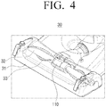
- the specific forms of the first motor, the drum, the brush and the suction inlet may be illustrated in FIG. 4 .
- the load applied to the first motor based on the type of surface to be cleaned may vary, and the size of the current supplied to the first motor 110 may vary accordingly.
- the load applied to the first motor based on surface to be cleaned being a carpet compared to the surface to be cleaned being a wood floor is greater, and the size of the current flowing to the first motor 110 accordingly also increases greatly. Even if the surface to be cleaned are both carpets, the size of the current flowing to the first motor 110 becomes relatively greater in the case the length of the carpet hair being longer and the friction coefficient being composed of a large material, than in the opposite case.
- the sensor 130 may sense the load applied to e first motor 110, and may also sense a first current based on the load. Specifically, the sensor 130 may sense the size of the current supplied to the first motor 110 based on a voltage value at both ends of the resistance of the first motor 110. Further, a hall sensor 130 using a hall voltage is mounted and may use a method of sensing current of the first motor 110, and additionally, may use a sensor 130 of various different methods
- the second motor 120 may generate suction pressure. Specifically, based on the driving instructions for the second motor 120 being input and power being provided to the second motor 120, an impeller is rotated by the driving of the second motor 120. Suction pressure is generated by the rotation of the impeller and air including impurities is suctioned into the suction inlet by the suction pressure. Herein, as the speed of the second motor 120 increases, the suction pressure becomes greater.
- the processor 140 controls the overall operation of the vacuum cleaner 100.
- the processor 140 controls the driving of the vacuum cleaner 100 based on a driving instruction of a user.
- the processor 140 may selectively control whether or not to drive the first motor 110. That is, the processor 140 may, based on a driving instruction by a user, control the function of rotating the brush installed on the drum according to the driving of the first motor to perform an auxiliary role for the function of suctioning the impurities based on suction pressure according to the driving of the second motor.
- the processor may then adjust suctioning force of the vacuum cleaner 100.
- the processor 140 may, based on manipulation of the suction force adjusting part by a user, adjust the size of the suction pressure generated by the second motor 120. Further, as described below, the processor 140 may control various configurations in the vacuum cleaner 100 such as a processor 140, a first motor 110, and a second motor 120.
- the load applied to the first motor 110 based by the type of surface to be cleaned may vary and the size of the current supplied to the first motor 110 may vary accordingly.
- the temperature of the first motor 110 may increase and a possibility of the first motor 110 being damaged may arise. If, the driving of the first motor 110 is terminated for a predetermined time considering these possibilities, as user may, in order to drive the first motor 110 again, press a power button to terminate the entire driving of the cleaner and then press the power button again to drive the cleaner again, having to endure an inconvenience.
- the processor 140 may control at least one from the first motor 110 and the second motor 120 according to the size of the load sensed from the sensor 130.
- the first threshold value may be a value corresponding to 50 % of the size of the load that may be sensed from the sensor 130
- the second threshold value smaller than the first threshold value may be a value corresponding to 30 % of the size of the load that may be sensed from the sensor 130
- the second threshold value greater than the first threshold value may be a value corresponding to 70% of the size of the load that may be sensed from the sensor 130.
- the numerical limitation such as the above are merely examples, and the size of the load corresponding to a specific threshold value may vary based on the first motor 100 used and other various factors. Accordingly, these threshold values are not limited to specific numerical values.
- the processor 140 may, based on the load sensed from the sensor 130 being a first threshold value or more, reduce the speed of the second motor 120.
- the processor 140 may adjust the voltage applied to the second motor 120 and reduce the speed of the second motor 120. For example, the processor 140 may, based on adjusting a size of a sine wave and frequency for the voltage applied to the second motor 120, reduce the speed of the second motor 120.
- various methods for reducing the speed of the second motor 120 may be applied to the present disclosure, and specific details for reducing the speed of the second motor 120 may also be applied with respect to controlling the increase in speed of the second motor 120.
- the suction pressure is increased, thereby the brush and the surface to be cleaned is strongly in contact and while the load applied to the first motor 110 becomes greater, as the speed of the second motor 120 decreases, the contact force of the brush and the surface to be cleaned is reduced and the load applied becomes lesser. Accordingly, based on the speed of the second motor 120 being reduced, the size of the current supplied to the first motor 110 may be reduced.
- the processor 140 may, based on the load sensed from the sensor 130 being a second threshold value or smaller than the first threshold value, the speed of the first motor 110 may be reduced. The control operation of this first motor 110 will be described in the description of FIG. 5 .
- the processor 140 may, based on the load sensed from the sensor 130 being a second threshold value or more, significantly reduce an effect according to the driving of the first motor 110 if the speed of the first motor is reduced excessively. Accordingly, the processor 140 may, based on maintaining the rotational force of the first motor 110, preferably reduce the speed of the first motor 110 within the range the current supplied to the first motor 110 may be reduced.
- the processor 140 may, based on the load sensed from the sensor 130 being a second threshold value or more, reduce the speed of the first motor 110 to 60 % to 80 % than a current speed.
- the range of speed reduction such as the above is merely an example, and may vary according to the first motor 110 used and other various factors. Accordingly, this reduction range is not limited to a specific numerical range.
- the processor 140 may, based on the load sensed from the sensor being a second threshold value or more, control the first motor 110 for the speed of the first motor to have a speed inversely proportional to a size of the sensed load.
- the processor 140 may, based on the load sensed from the sensor 130 being a second threshold value or more, reduce speed of the first motor 110 to 80 % of a current speed, and may successively reduce to a value arriving from 100 % to 80 % inversely proportional to the size of the sensed load increasing.
- the processor 140 may, based on the load sensed from the sensor 130 being a third threshold value or greater than the first threshold value, terminate the driving of the first motor 110.
- the processor 140 may, based on the load sensed from the sensor 130 being a specific threshold value or more, perform control concurrently, and may perform control after reaching a specific threshold value or more and a predetermined time has passed.
- the processor 140 may, based on the load sensed from the sensor 130 being a third threshold value or more, terminate driving of the first motor concurrently, and based on the load sensed from the sensor 130 being a third threshold value or more and thereafter not falling below the third threshold value for 5 seconds, terminate driving of the first motor 110.
- the processor 140 may, based on the load sensed from the sensor 130 being a second threshold value or more, first reduce the speed of the first motor 110, and based on the load sensed from the sensor 130 being a first threshold value or greater than the second threshold value despite the above, may reduce the speed of the second motor 120.
- the processor 140 may, based on the load sensed from the sensor 130 being a second threshold value or more, first reduce the speed of the second motor 120, and based on the load sensed from the sensor 130 being a first threshold value or greater than the second threshold value, may reduce the speed of the first motor 110.
- the control process of a processor 140 in the case a load of a specific threshold value or more is sensed from the sensor 130 is described, but as described below, even in the case a load of less than a specific threshold value is sensed from the sensor 130, the processor may control at least one from the first motor 110 and the second motor 120.
- the processor 140 may be required to control the first motor 110 or the second motor 120 again.
- the processor 140 may, based on the load sensed from the sensor 130 being less than a third threshold value, drive the first motor 110.
- the processor 140 may re-drive the terminated first motor 110 based on the processor 140 terminating the driving of the first motor when the load sensed from the sensor 130 reaches a third threshold value or more, and thereafter based on the load sensed from the sensor 130 being less than the third threshold value, the processor 140 may re-drive the terminated first motor 110.
- the processor 140 may not perform a particular control.
- the processor 140 may, based on the load sensed from the sensor 130 being less than a first threshold value, increase speed of the second motor 120.
- the processor 140 reduces the speed of the second motor 120 based on the load sensed from the sensor 130 reaching a first threshold value or more, and in case the load sensed again from the sensor 130 is less than the first threshold value, the reduced speed of the second motor may be increased.
- the processor 140 may not perform a particular control.
- the processor 140 may, based on the load sensed from the sensor 130 being less than a second threshold value, increase speed of the first motor 110.
- the processor 140 reduces the speed of the first motor 110 based on the load sensed from the sensor 130 being a second threshold value or more, and in case the load sensed again from the sensor 130 is less than the second threshold value, the reduced speed of the first motor 110 may be increased.
- the processor 140 may not perform a particular control.
- the processor 140 may, based on the load sensed from the sensor 130 being less than a specific threshold value, perform control concurrently, and may perform control after reaching less than a specific threshold value and a predetermined time has passed.
- the processor 140 may, based on the load sensed from the sensor 130 being less than a specific threshold value, terminate driving of the first motor 110 concurrently, or after the load sensed from the sensor 130 becomes less than the third threshold value, may terminate driving of the first motor 110 in case the load fails to reach the third threshold value or more for five seconds.
- the processor 140 may, based on the load sensed from the sensor 130 being less than a first threshold value, first reduce the speed of the second motor 120, and based on the load sensed from the sensor 130 being less than a second threshold value smaller than the first threshold value despite the above, may reduce the speed of the first motor 110.
- the processor 140 may, based on the load sensed from the sensor 130 being less than a first threshold value, first reduce the speed of the first motor 110, and based on the load sensed from the sensor 130 being less than a second threshold value smaller than the first threshold value despite the above, may reduce the speed of the second motor 120.
- the vacuum cleaner 100 may further include configurations such as those illustrated in FIG. 2 .
- the specific configuration of the vacuum cleaner 100 will be described below with reference to FIG. 2 .
- FIG. 2 is a block diagram provided to show a specific configuration of a vacuum cleaner 100 according to an embodiment of the present disclosure.
- the vacuum cleaner 100 may include a first motor 110, a second motor 120, a sensor 130, a processor 140, a manipulation input part 160, a user interface part 170, and a battery 150.
- the configuration of the first motor 110, the second motor 120 and the sensor 130 is the same as the configuration in FIG. 1 and repetitive descriptions will be omitted.
- the manipulation input part 160 includes a power button, a suction force adjusting part, and the like, and may receive input of user manipulation of the vacuum cleaner 100.
- the user may, through the power button, input driving instruction of the vacuum cleaner 100, and the user may selectively manipulate whether or not to drive the first motor 110. That is, the user may manipulate the function of rotating the brush mounted on the drum according to the driving of the first motor as an auxiliary role for the function of suctioning the impurities based on suction pressure according to the driving of the second motor.
- the user may manipulate the suction force adjusting part to adjust the size of the suction pressure generated by the second motor 120.
- the user interface part 170 is configured to interact with the user of the vacuum cleaner 100.
- the user interface part 170 may include an indicator, and may also additionally include a vibrator, a speaker, and the like. A specific embodiment related thereto will be described with the description for FIG. 6 .
- the processor 140 may, based on the user input being input to the manipulation input part 160, control each configuration of the vacuum cleaner 100. Further, the processor 140 may control the user interface part 170, and may also receive input on user interaction from the user interface part 170.
- the processor 140 may include a read-only memory (ROM), a random-access memory (RAM), a graphic processing unit (GPU), a central processing unit (CPU), and a bus. Further, the ROM, RAM, GPU, CPU or the like may be inter-coupled through the bus.
- ROM read-only memory
- RAM random-access memory
- GPU graphic processing unit
- CPU central processing unit
- the vacuum cleaner 100 includes a battery 150, and through the battery 150, may provide power to each configuration in the vacuum cleaner 100.
- the battery 150 may supply power to the first motor 110, the second motor 120, the sensor 130, the processor 140, the manipulation input part 160, the user interface part 170, and the like.
- the vacuum cleaner 100 may further include a secondary battery providing power to the first motor 110 and the second motor 120.
- the secondary battery may be a nickel-cadmium (NiCd) battery, a nickel metal hydride (NiMH) battery, a lithium ion (Li-ion) battery, a lithium ion polymer (Li-ion polymer) battery) or the like, but are not limited to the types thereof.
- NiCd nickel-cadmium
- NiMH nickel metal hydride
- Li-ion lithium ion
- Li-ion polymer Li-ion polymer
- the vacuum cleaner 100 may control the operation of the motor adaptively according to the load of the motor rotating the drum mounted with a brush. Accordingly, the user of the vacuum cleaner 100 may effectively clean without any inconvenience regardless of the use environment according to the various surfaces to be cleaned, as well as reduce the percentage of failures occurring in the vacuum cleaner 100.
- FIG. 3 is a diagram provided to show an exemplary form of a vacuum cleaner 100 of the present disclosure.
- the vacuum cleaner 100 of the present disclosure may include a second motor and a main body 20 including an impeller rotated by the second motor 120, a suction module 30 coupled by the main body 20, and a handle 10 including a manipulation input part 160 and a user interface part 170.
- a handy-stick type vacuum cleaner 100 is shown as an example among the various types of vacuum cleaners 100 in FIG. 3 , the present disclosure it not limited to a specific type of vacuum cleaner 100. That is, the present disclosure may be implemented in a vacuum cleaner 100 of various types including a second motor 120 generating suction pressure together with the first motor 110 to rotate the drum mounted with a brush.
- FIG. 4 is a diagram provided to specifically show a form of a suction module 30 of FIG. 3 .
- the suction module 30 may, as shown in FIG. 4 , include a suction inlet 31 suctioning air included with impurities, a drum 32 roated by the first motor 110, a brush 33 mounted on the drum 32, and a first motor 110 rotating the drum 32 mounted with the brush 33.
- a suction module 30 Various types according to use thereof such as a general type and a bedding type are present in a suction module 30, and a various types capable of being mounted with a brush 33, a drum 32, and a first motor 110 may be applied to the various embodiments of the present disclosure.
- the suction module 30 may vary depending on the length of the brush 33, material or the like included therein. Further, the position mounted with the brush 33 in the suction module 30 may be variably selected.
- the size of the load the specific suction module 30 has for the same surface to be cleaned may vary based on the length, material, mounting position or the like of the selected brush 33.
- the size of the load applied to the first motor 110 and the size of the current therefrom may not only vary according to the type of the surface to be cleaned but also to the type of the suction module 30.
- the vacuum cleaner 100 may further include a suction module 30 mounted to be detachable from the main body 20 and includes a drum 32 mounted with a brush 33 and a first motor 110, and the processor 140 may identify the type of the suction module 30 and based on the threshold value corresponding to the confirmed type, may control the speed of the second motor 120.
- FIG. 5 is a diagram provided to specifically describe a control operation of a first motor 110 of the present disclosure.
- the processor 140 may, based on the load sensed from the sensor 130 being a second threshold value or smaller than the first threshold value, reduce the speed of the first motor 110.
- the processor 140 may, based on the current value of the first motor 110 calculated according to the voltage at both ends of the resistance, control the voltage duty value applied to the first motor 110 through a proportional integral (PI) controller under a feedback system. Further, the size of the current supplied to the first motor 110 may hereby be controlled, and the speed of the first motor 110 may be controlled.
- PI proportional integral
- the processor 140 may, based on the load sensed from the sensor 130 being a first threshold value or more, reduce the voltage duty value applied to the first motor 110 to 70 %.
- the voltage duty value such as the above, while maintaining a rotational force of the first motor 110, may be determined within the range that may decrease the current supplied to the first motor 110.
- the processor 140 may, based on the load sensed from the sensor 130 being a first threshold value or more, reduce the voltage duty value applied to the first motor 100 to 70 %, and may successively reduce the value arriving from 100 % to 70 % inversely proportional to the size of the sensed load increasing.
- the reduction range of the voltage duty such as the above is merely an example, and may vary based on the first motor 110 used and other various factors. Accordingly, the reduction range herein is not limited by a specific numerical limitation.
- FIG. 6 is a diagram provided describe an embodiment of a vacuum cleaner 100 provided with a user interface part 170.
- the handle 10 of the vacuum cleaner 100 may include an indicator 12 corresponding to one from a power button 11 and a user interface part 170.
- the user interface part 170 may include not only the indicator 12, but also a vibrator, a speaker, and the like.
- the suction module 30 may be detachable from the main body 20, and the size of the load applied to the first motor 110 and the size of the current therefrom may vary according to the type of the suction module 30. Further, information on the load per the suction module 30 such as the above may be provided to the user in advance.
- a notification guiding to exchange the section module 30 is provided to the user, and based on the user selecting and exchanging the suction module 30 appropriate to the use environment, the object of the present disclosure may be achieved.
- the vacuum cleaner 100 may further include a user interface part 170, and based on the load sensed from the sensor 130 being a first threshold value or more, the user interface part 170 may provide a notification guiding to exchange to a suction module 30 with a relatively lesser load than the currently mounted suction module 30.
- the notification such as the above may be implemented in a method of providing visual information to the user through a sign.
- the vacuum cleaner 100 may, as shown in FIG. 6 , further include an indicator 12 at a position easily recognizable visually by the user at the upper end of the handle 10 or the like, and may provide a notification guiding to exchange the suction module 30 to the user through switching on or off lighting or changing a lighted colord of the indicator 12.
- the indicator 12 may be a light emitting diode (LED) indicator, but are not limited to the type thereof.
- the providing of visual information such as the above may further include a display by the vacuum cleaner 100, and may consist of a method displaying a text guiding to exchange the suction module 30 through the display.
- the notifications such as the above may be implemented in a method of providing tactile information to the user through vibration.
- the vacuum cleaner 100 may further include a vibrator at a position easily recognizable tactilely by the user at the upper end of the handle 10 or the like, and may provide a notification guiding to exchange the suction module 30 by delivering a specific vibration to the user through the vibrator.
- the notifications such as the above may be implemented in a method of providing auditory information to the user through voice.
- the vacuum cleaner may further include a speaker at a position easily recognizable audibly by the user at the upper end of the handle 10 or the like, and may provide a notification guiding to exchange the suction module 30 by delivering a specific voice to the user through the speaker.
- FIG. 7 is a flow chart provided to describe a controlling method of a vacuum cleaner 100 according to an embodiment of the present disclosure.
- the second motor 120 is used to generate suction pressure S710, and the first motor 110 is used to rotate the drum 32 mounted with the brush 33 S720.
- the load applied to the first motor 110 is sensed S730, and at least one from the first motor 110 and the second motor 120 is controlled according to the size of the sensed load S740.
- the specific description regarding this control process will be described with reference to FIG. 8 .
- FIG. 8 is a flow chart provided to specifically describe a controlling method of a vacuum cleaner 100 according to various embodiments of the present disclosure. That is, based on the sensed load in sensing the load applied to the first motor as described in FIG. 7 , the controlling at least one from the first motor and the second motor is specified below to describe various embodiments.
- the speed of the second motor 120 may be reduced S820.
- the speed of the first motor 110 may be reduced S840.
- driving of the first motor 110 may be terminated S860.
- the first motor 110 may be driven S870.
- the speed of the second motor 120 may be increased S880.
- the speed of the first motor 110 may be increased S890.
- a particular control may not be performed.
- a particular control may not be performed even if the sensed load is less than the third threshold value.
- control method of the vacuum cleaner according to the present disclosure may, based on the sensed load being a second threshold value or more, reduce the speed of the first motor to 60 % to 80 % than a current speed.
- the first motor may be controlled for the speed of the first motor 110 to have a speed inversely proportional to the size of the sensed load.
- the meaning of the used threshold value, the meaning of the threshold value or more and less than the threshold value, the increase and decrease of speed of the first motor, the increase and decrease of speed of the second motor, control of whether or not to drive the first motor, and the like have been described above, and a repetitive description thereof will be omitted.
- control method of the vacuum cleaner 100 may be implemented to other various embodiments. However, the detailed description thereof have also been described above in the process of describing the processor 140 of the vacuum cleaner 100 according to the present disclosure, and thus a repetitive description thereof will be omitted.
- the operation of the motor may be adaptively controlled according to the load of the motor rotating the drum 32 mounted with the brush 33. Accordingly, the user of the vacuum cleaner 100 may effectively clean without any inconvenience regardless of the use environment according to the various surfaces to be cleaned, as well as reduce the percentage of failures occurring in the vacuum cleaner 100.
- the control method of the vacuum cleaner 100 as in FIGS. 7 and 8 may be executed on a vacuum cleaner 100 having the configuration of FIG. 1 or FIG. 2 , and may also be executed on a vacuum cleaner 100 having other configurations.
- the control method of a vacuum cleaner 100 may be implemented as a program and provided to the vacuum cleaner 100.
- the program including the control method of a vacuum cleaner 100 may be stored and provided in a non-transitory computer readable medium.
Landscapes
- Engineering & Computer Science (AREA)
- Mechanical Engineering (AREA)
- Power Engineering (AREA)
- Nozzles For Electric Vacuum Cleaners (AREA)
- Electric Vacuum Cleaner (AREA)
Priority Applications (2)
| Application Number | Priority Date | Filing Date | Title |
|---|---|---|---|
| EP22208265.3A EP4154780B1 (de) | 2018-05-18 | 2019-05-10 | Staubsauger und verfahren zur steuerung davon |
| EP21177966.5A EP3900598B1 (de) | 2018-05-18 | 2019-05-10 | Staubsauger und verfahren zu dessen steuerung |
Applications Claiming Priority (2)
| Application Number | Priority Date | Filing Date | Title |
|---|---|---|---|
| KR1020180056968A KR102130691B1 (ko) | 2018-05-18 | 2018-05-18 | 진공 청소기 및 진공 청소기의 제어방법 |
| PCT/KR2019/005660 WO2019221457A1 (ko) | 2018-05-18 | 2019-05-10 | 진공 청소기 및 진공 청소기의 제어방법 |
Related Child Applications (3)
| Application Number | Title | Priority Date | Filing Date |
|---|---|---|---|
| EP22208265.3A Division EP4154780B1 (de) | 2018-05-18 | 2019-05-10 | Staubsauger und verfahren zur steuerung davon |
| EP21177966.5A Division EP3900598B1 (de) | 2018-05-18 | 2019-05-10 | Staubsauger und verfahren zu dessen steuerung |
| EP21177966.5A Division-Into EP3900598B1 (de) | 2018-05-18 | 2019-05-10 | Staubsauger und verfahren zu dessen steuerung |
Publications (3)
| Publication Number | Publication Date |
|---|---|
| EP3632282A1 true EP3632282A1 (de) | 2020-04-08 |
| EP3632282A4 EP3632282A4 (de) | 2020-08-05 |
| EP3632282B1 EP3632282B1 (de) | 2021-11-03 |
Family
ID=68540578
Family Applications (3)
| Application Number | Title | Priority Date | Filing Date |
|---|---|---|---|
| EP19804511.4A Active EP3632282B1 (de) | 2018-05-18 | 2019-05-10 | Staubsauger und verfahren zur steuerung eines staubsaugers |
| EP21177966.5A Active EP3900598B1 (de) | 2018-05-18 | 2019-05-10 | Staubsauger und verfahren zu dessen steuerung |
| EP22208265.3A Active EP4154780B1 (de) | 2018-05-18 | 2019-05-10 | Staubsauger und verfahren zur steuerung davon |
Family Applications After (2)
| Application Number | Title | Priority Date | Filing Date |
|---|---|---|---|
| EP21177966.5A Active EP3900598B1 (de) | 2018-05-18 | 2019-05-10 | Staubsauger und verfahren zu dessen steuerung |
| EP22208265.3A Active EP4154780B1 (de) | 2018-05-18 | 2019-05-10 | Staubsauger und verfahren zur steuerung davon |
Country Status (5)
| Country | Link |
|---|---|
| US (2) | US11369244B2 (de) |
| EP (3) | EP3632282B1 (de) |
| KR (1) | KR102130691B1 (de) |
| CN (1) | CN111031874B (de) |
| WO (1) | WO2019221457A1 (de) |
Cited By (1)
| Publication number | Priority date | Publication date | Assignee | Title |
|---|---|---|---|---|
| EP4467050A1 (de) * | 2023-05-25 | 2024-11-27 | Beijing Xiaomi Mobile Software Co., Ltd. | Verfahren und vorrichtung zur identifizierung des bürstentyps, reinigungsvorrichtung und speichermedium |
Families Citing this family (10)
| Publication number | Priority date | Publication date | Assignee | Title |
|---|---|---|---|---|
| KR102306753B1 (ko) * | 2019-07-19 | 2021-09-30 | 엘지전자 주식회사 | 청소기의 제어 방법 |
| KR20210073120A (ko) * | 2019-12-10 | 2021-06-18 | 엘지전자 주식회사 | 맞춤형 청소 정보를 제공하는 방법과, 청소기와, 그 청소기를 제어하는 방법 |
| GB2596857B (en) | 2020-07-10 | 2023-01-04 | Dyson Technology Ltd | Vacuum cleaner |
| GB2596861B (en) * | 2020-07-10 | 2023-01-04 | Dyson Technology Ltd | Vacuum cleaner |
| KR20220107749A (ko) * | 2021-01-26 | 2022-08-02 | 엘지전자 주식회사 | 상향식 전력선 통신을 수행하는 전자 장치 및 그 동작 방법 |
| EP4505926A4 (de) * | 2022-06-02 | 2025-08-06 | Samsung Electronics Co Ltd | Reinigungssystem mit fähigkeit zur selbstdiagnose und selbstdiagnoseverfahren des reinigungssystems |
| EP4473892A4 (de) | 2022-07-28 | 2025-08-13 | Samsung Electronics Co Ltd | Staubsauger und steuerungsverfahren dafür |
| KR20240017227A (ko) * | 2022-07-28 | 2024-02-07 | 삼성전자주식회사 | 진공 청소기 및 그 제어 방법 |
| DE102022121452A1 (de) * | 2022-08-25 | 2024-03-07 | Miele & Cie. Kg | Staubsauger, vorzugsweise Handstaubsauger |
| CN116115146A (zh) * | 2023-01-17 | 2023-05-16 | 广东贝尔斯顿智能科技有限公司 | 扫地机器人控制方法、控制器、计算机可读存储介质 |
Family Cites Families (31)
| Publication number | Priority date | Publication date | Assignee | Title |
|---|---|---|---|---|
| JPS5176872A (en) | 1974-12-26 | 1976-07-03 | Olympus Optical Co | Hakunetsudenkyuno tentosochi |
| JP2523930B2 (ja) | 1990-04-16 | 1996-08-14 | 株式会社日立製作所 | 電気掃除機の製御方法 |
| EP0458057B1 (de) | 1990-04-16 | 1995-02-01 | Hitachi, Ltd. | Verfahren zum Betreiben eines Staubsaugers |
| EP0479609A3 (en) | 1990-10-05 | 1993-01-20 | Hitachi, Ltd. | Vacuum cleaner and control method thereof |
| KR930005714B1 (ko) * | 1991-06-25 | 1993-06-24 | 주식회사 금성사 | 진공 청소기의 흡입력 제어방법 및 장치 |
| TW212231B (de) | 1991-08-01 | 1993-09-01 | Hitachi Seisakusyo Kk | |
| JP2956300B2 (ja) * | 1991-08-30 | 1999-10-04 | 株式会社日立製作所 | 電気掃除機の制御方法 |
| KR0133057B1 (ko) | 1991-09-20 | 1998-04-16 | 강진구 | 진공 청소기의 모터출력 제어장치 |
| CN1494861A (zh) * | 1993-07-16 | 2004-05-12 | 株式会社金星社 | 真空吸尘器的吸入力的控制装置及方法 |
| JP3505957B2 (ja) | 1997-06-03 | 2004-03-15 | 三菱電機株式会社 | 電気掃除機 |
| JP4552336B2 (ja) * | 2001-02-27 | 2010-09-29 | パナソニック株式会社 | 電気掃除機 |
| JP4726392B2 (ja) | 2001-03-16 | 2011-07-20 | ヴィジョン・ロボティクス・コーポレーション | 自律的に移動するキャニスタ型真空掃除機 |
| JP2003135320A (ja) | 2001-11-02 | 2003-05-13 | Matsushita Electric Ind Co Ltd | 電動送風機およびそれを用いた電気掃除機 |
| US7237298B2 (en) * | 2003-09-19 | 2007-07-03 | Royal Appliance Mfg. Co. | Sensors and associated methods for controlling a vacuum cleaner |
| US7203993B2 (en) * | 2003-12-23 | 2007-04-17 | The Hoover Company | Suction nozzle height adjustment and control arrangement |
| ATE374562T1 (de) * | 2004-04-08 | 2007-10-15 | Grey Technology Ltd | Oberflächenreinigungsvorrichtung |
| GB0408120D0 (en) | 2004-04-08 | 2004-05-19 | Grey Technology Ltd | Surface cleaning apparatus |
| KR100565260B1 (ko) * | 2004-10-13 | 2006-03-30 | 엘지전자 주식회사 | 로봇 청소기의 브러시 모터 저속 검출회로 |
| WO2007065034A1 (en) * | 2005-12-02 | 2007-06-07 | Irobot Corporation | Modular robot |
| ES2706729T3 (es) | 2005-12-02 | 2019-04-01 | Irobot Corp | Sistema de robot |
| US20100229892A1 (en) * | 2008-02-21 | 2010-09-16 | Euro-Pro Operating Llc | Surface Cleaning Apparatus With Automatic Brush Speed Adjustment |
| KR100963753B1 (ko) | 2008-03-31 | 2010-06-14 | 엘지전자 주식회사 | 자동청소기 |
| JP2010057530A (ja) | 2008-09-01 | 2010-03-18 | Panasonic Corp | 電気掃除機用吸込具及び電気掃除機 |
| DE102009018338A1 (de) * | 2009-04-23 | 2010-11-04 | Miele & Cie. Kg | Verfahren zum Betrieb eines Vorsatzgeräts für einen Staubsauger und korrespondierendes Vorsatzgerät |
| JP5492799B2 (ja) * | 2011-01-25 | 2014-05-14 | 日立アプライアンス株式会社 | 電気掃除機 |
| JP2012217787A (ja) * | 2011-04-14 | 2012-11-12 | Panasonic Corp | 電気掃除機 |
| GB2513193B (en) | 2013-04-19 | 2015-06-03 | Dyson Technology Ltd | Air moving appliance with on-board diagnostics |
| GB2515082B (en) | 2013-06-13 | 2015-10-28 | Dyson Technology Ltd | Vacuum cleaner |
| GB2515084B (en) * | 2013-06-13 | 2015-10-28 | Dyson Technology Ltd | Surface cleaning appliance |
| CN106419644B (zh) * | 2015-08-04 | 2020-10-16 | 德昌电机(深圳)有限公司 | 旋转搅拌机构的控制方法及控制系统 |
| WO2018124544A1 (ko) * | 2016-12-30 | 2018-07-05 | 엘지전자 주식회사 | 로봇 청소기 |
-
2018
- 2018-05-18 KR KR1020180056968A patent/KR102130691B1/ko active Active
-
2019
- 2019-05-10 EP EP19804511.4A patent/EP3632282B1/de active Active
- 2019-05-10 EP EP21177966.5A patent/EP3900598B1/de active Active
- 2019-05-10 CN CN201980004042.3A patent/CN111031874B/zh active Active
- 2019-05-10 EP EP22208265.3A patent/EP4154780B1/de active Active
- 2019-05-10 US US16/637,924 patent/US11369244B2/en active Active
- 2019-05-10 WO PCT/KR2019/005660 patent/WO2019221457A1/ko not_active Ceased
-
2022
- 2022-06-08 US US17/835,406 patent/US11779181B2/en active Active
Cited By (1)
| Publication number | Priority date | Publication date | Assignee | Title |
|---|---|---|---|---|
| EP4467050A1 (de) * | 2023-05-25 | 2024-11-27 | Beijing Xiaomi Mobile Software Co., Ltd. | Verfahren und vorrichtung zur identifizierung des bürstentyps, reinigungsvorrichtung und speichermedium |
Also Published As
| Publication number | Publication date |
|---|---|
| US11779181B2 (en) | 2023-10-10 |
| EP4154780C0 (de) | 2024-05-01 |
| KR102130691B1 (ko) | 2020-08-05 |
| US20220296066A1 (en) | 2022-09-22 |
| KR20190131932A (ko) | 2019-11-27 |
| CN111031874B (zh) | 2025-04-22 |
| EP4154780A1 (de) | 2023-03-29 |
| EP4154780B1 (de) | 2024-05-01 |
| WO2019221457A1 (ko) | 2019-11-21 |
| US11369244B2 (en) | 2022-06-28 |
| US20200170469A1 (en) | 2020-06-04 |
| EP3632282A4 (de) | 2020-08-05 |
| EP3900598A1 (de) | 2021-10-27 |
| CN111031874A (zh) | 2020-04-17 |
| EP3632282B1 (de) | 2021-11-03 |
| EP3900598B1 (de) | 2022-11-30 |
Similar Documents
| Publication | Publication Date | Title |
|---|---|---|
| EP3632282B1 (de) | Staubsauger und verfahren zur steuerung eines staubsaugers | |
| EP3384820B1 (de) | Staubsauger und griff für einen reiniger | |
| US7676879B1 (en) | Battery-powered sewer and drain cleaner | |
| CN207613370U (zh) | 具有动作感应器的吹风机 | |
| EP3000374A2 (de) | Staubsauger | |
| JP2019510455A (ja) | 家庭用電化製品および家庭用電化製品の駆動方法 | |
| KR102436006B1 (ko) | 진공 청소기 및 진공 청소기의 제어방법 | |
| EP2000072A3 (de) | Dampfstaubsauger mit elektrischer Leistungssteuerfunktion und Verfahren dafür | |
| KR102662526B1 (ko) | 진공 청소기 및 진공 청소기의 제어방법 | |
| CN100566642C (zh) | 电真空吸尘器 | |
| KR102301377B1 (ko) | 모터구동장치, 이를 포함하는 청소기, 및 그 제어방법 | |
| WO2015025470A1 (ja) | 電気掃除機 | |
| EP3525648B1 (de) | Handgehaltenes oberflächenreinigungsgerät | |
| JP7098917B2 (ja) | 電気掃除機 | |
| EP4268695B1 (de) | Staubsauger und verfahren zur steuerung davon | |
| JP6711089B2 (ja) | 電気掃除機 | |
| JP2012055533A (ja) | 電気掃除機 | |
| JP2015054155A (ja) | 電気掃除機 | |
| CN108462245A (zh) | 由设备和基站组成的系统 | |
| CN108605667B (zh) | 电动工具 | |
| US20210307580A1 (en) | System and method for providing power to a motor | |
| JP5075453B2 (ja) | 電気掃除機 | |
| JP2015167705A (ja) | 電気掃除機 | |
| JP2013068158A (ja) | 空気圧縮機 | |
| JP2020018412A (ja) | クリーナ |
Legal Events
| Date | Code | Title | Description |
|---|---|---|---|
| STAA | Information on the status of an ep patent application or granted ep patent |
Free format text: STATUS: THE INTERNATIONAL PUBLICATION HAS BEEN MADE |
|
| PUAI | Public reference made under article 153(3) epc to a published international application that has entered the european phase |
Free format text: ORIGINAL CODE: 0009012 |
|
| STAA | Information on the status of an ep patent application or granted ep patent |
Free format text: STATUS: REQUEST FOR EXAMINATION WAS MADE |
|
| 17P | Request for examination filed |
Effective date: 20200103 |
|
| AK | Designated contracting states |
Kind code of ref document: A1 Designated state(s): AL AT BE BG CH CY CZ DE DK EE ES FI FR GB GR HR HU IE IS IT LI LT LU LV MC MK MT NL NO PL PT RO RS SE SI SK SM TR |
|
| AX | Request for extension of the european patent |
Extension state: BA ME |
|
| A4 | Supplementary search report drawn up and despatched |
Effective date: 20200703 |
|
| RIC1 | Information provided on ipc code assigned before grant |
Ipc: A47L 9/04 20060101AFI20200629BHEP Ipc: H02P 5/46 20060101ALI20200629BHEP Ipc: A47L 9/28 20060101ALI20200629BHEP |
|
| STAA | Information on the status of an ep patent application or granted ep patent |
Free format text: STATUS: EXAMINATION IS IN PROGRESS |
|
| 17Q | First examination report despatched |
Effective date: 20210201 |
|
| GRAP | Despatch of communication of intention to grant a patent |
Free format text: ORIGINAL CODE: EPIDOSNIGR1 |
|
| STAA | Information on the status of an ep patent application or granted ep patent |
Free format text: STATUS: GRANT OF PATENT IS INTENDED |
|
| DAV | Request for validation of the european patent (deleted) | ||
| DAX | Request for extension of the european patent (deleted) | ||
| INTG | Intention to grant announced |
Effective date: 20210625 |
|
| GRAS | Grant fee paid |
Free format text: ORIGINAL CODE: EPIDOSNIGR3 |
|
| GRAA | (expected) grant |
Free format text: ORIGINAL CODE: 0009210 |
|
| STAA | Information on the status of an ep patent application or granted ep patent |
Free format text: STATUS: THE PATENT HAS BEEN GRANTED |
|
| AK | Designated contracting states |
Kind code of ref document: B1 Designated state(s): AL AT BE BG CH CY CZ DE DK EE ES FI FR GB GR HR HU IE IS IT LI LT LU LV MC MK MT NL NO PL PT RO RS SE SI SK SM TR |
|
| REG | Reference to a national code |
Ref country code: GB Ref legal event code: FG4D |
|
| REG | Reference to a national code |
Ref country code: AT Ref legal event code: REF Ref document number: 1443215 Country of ref document: AT Kind code of ref document: T Effective date: 20211115 Ref country code: CH Ref legal event code: EP |
|
| REG | Reference to a national code |
Ref country code: DE Ref legal event code: R096 Ref document number: 602019009006 Country of ref document: DE |
|
| REG | Reference to a national code |
Ref country code: IE Ref legal event code: FG4D |
|
| REG | Reference to a national code |
Ref country code: NL Ref legal event code: FP |
|
| REG | Reference to a national code |
Ref country code: LT Ref legal event code: MG9D |
|
| REG | Reference to a national code |
Ref country code: AT Ref legal event code: MK05 Ref document number: 1443215 Country of ref document: AT Kind code of ref document: T Effective date: 20211103 |
|
| PG25 | Lapsed in a contracting state [announced via postgrant information from national office to epo] |
Ref country code: RS Free format text: LAPSE BECAUSE OF FAILURE TO SUBMIT A TRANSLATION OF THE DESCRIPTION OR TO PAY THE FEE WITHIN THE PRESCRIBED TIME-LIMIT Effective date: 20211103 Ref country code: LT Free format text: LAPSE BECAUSE OF FAILURE TO SUBMIT A TRANSLATION OF THE DESCRIPTION OR TO PAY THE FEE WITHIN THE PRESCRIBED TIME-LIMIT Effective date: 20211103 Ref country code: FI Free format text: LAPSE BECAUSE OF FAILURE TO SUBMIT A TRANSLATION OF THE DESCRIPTION OR TO PAY THE FEE WITHIN THE PRESCRIBED TIME-LIMIT Effective date: 20211103 Ref country code: BG Free format text: LAPSE BECAUSE OF FAILURE TO SUBMIT A TRANSLATION OF THE DESCRIPTION OR TO PAY THE FEE WITHIN THE PRESCRIBED TIME-LIMIT Effective date: 20220203 Ref country code: AT Free format text: LAPSE BECAUSE OF FAILURE TO SUBMIT A TRANSLATION OF THE DESCRIPTION OR TO PAY THE FEE WITHIN THE PRESCRIBED TIME-LIMIT Effective date: 20211103 |
|
| PG25 | Lapsed in a contracting state [announced via postgrant information from national office to epo] |
Ref country code: IS Free format text: LAPSE BECAUSE OF FAILURE TO SUBMIT A TRANSLATION OF THE DESCRIPTION OR TO PAY THE FEE WITHIN THE PRESCRIBED TIME-LIMIT Effective date: 20220303 Ref country code: SE Free format text: LAPSE BECAUSE OF FAILURE TO SUBMIT A TRANSLATION OF THE DESCRIPTION OR TO PAY THE FEE WITHIN THE PRESCRIBED TIME-LIMIT Effective date: 20211103 Ref country code: PT Free format text: LAPSE BECAUSE OF FAILURE TO SUBMIT A TRANSLATION OF THE DESCRIPTION OR TO PAY THE FEE WITHIN THE PRESCRIBED TIME-LIMIT Effective date: 20220303 Ref country code: PL Free format text: LAPSE BECAUSE OF FAILURE TO SUBMIT A TRANSLATION OF THE DESCRIPTION OR TO PAY THE FEE WITHIN THE PRESCRIBED TIME-LIMIT Effective date: 20211103 Ref country code: NO Free format text: LAPSE BECAUSE OF FAILURE TO SUBMIT A TRANSLATION OF THE DESCRIPTION OR TO PAY THE FEE WITHIN THE PRESCRIBED TIME-LIMIT Effective date: 20220203 Ref country code: LV Free format text: LAPSE BECAUSE OF FAILURE TO SUBMIT A TRANSLATION OF THE DESCRIPTION OR TO PAY THE FEE WITHIN THE PRESCRIBED TIME-LIMIT Effective date: 20211103 Ref country code: HR Free format text: LAPSE BECAUSE OF FAILURE TO SUBMIT A TRANSLATION OF THE DESCRIPTION OR TO PAY THE FEE WITHIN THE PRESCRIBED TIME-LIMIT Effective date: 20211103 Ref country code: GR Free format text: LAPSE BECAUSE OF FAILURE TO SUBMIT A TRANSLATION OF THE DESCRIPTION OR TO PAY THE FEE WITHIN THE PRESCRIBED TIME-LIMIT Effective date: 20220204 Ref country code: ES Free format text: LAPSE BECAUSE OF FAILURE TO SUBMIT A TRANSLATION OF THE DESCRIPTION OR TO PAY THE FEE WITHIN THE PRESCRIBED TIME-LIMIT Effective date: 20211103 |
|
| PG25 | Lapsed in a contracting state [announced via postgrant information from national office to epo] |
Ref country code: SM Free format text: LAPSE BECAUSE OF FAILURE TO SUBMIT A TRANSLATION OF THE DESCRIPTION OR TO PAY THE FEE WITHIN THE PRESCRIBED TIME-LIMIT Effective date: 20211103 Ref country code: SK Free format text: LAPSE BECAUSE OF FAILURE TO SUBMIT A TRANSLATION OF THE DESCRIPTION OR TO PAY THE FEE WITHIN THE PRESCRIBED TIME-LIMIT Effective date: 20211103 Ref country code: RO Free format text: LAPSE BECAUSE OF FAILURE TO SUBMIT A TRANSLATION OF THE DESCRIPTION OR TO PAY THE FEE WITHIN THE PRESCRIBED TIME-LIMIT Effective date: 20211103 Ref country code: EE Free format text: LAPSE BECAUSE OF FAILURE TO SUBMIT A TRANSLATION OF THE DESCRIPTION OR TO PAY THE FEE WITHIN THE PRESCRIBED TIME-LIMIT Effective date: 20211103 Ref country code: DK Free format text: LAPSE BECAUSE OF FAILURE TO SUBMIT A TRANSLATION OF THE DESCRIPTION OR TO PAY THE FEE WITHIN THE PRESCRIBED TIME-LIMIT Effective date: 20211103 Ref country code: CZ Free format text: LAPSE BECAUSE OF FAILURE TO SUBMIT A TRANSLATION OF THE DESCRIPTION OR TO PAY THE FEE WITHIN THE PRESCRIBED TIME-LIMIT Effective date: 20211103 |
|
| REG | Reference to a national code |
Ref country code: DE Ref legal event code: R097 Ref document number: 602019009006 Country of ref document: DE |
|
| PLBE | No opposition filed within time limit |
Free format text: ORIGINAL CODE: 0009261 |
|
| STAA | Information on the status of an ep patent application or granted ep patent |
Free format text: STATUS: NO OPPOSITION FILED WITHIN TIME LIMIT |
|
| 26N | No opposition filed |
Effective date: 20220804 |
|
| PG25 | Lapsed in a contracting state [announced via postgrant information from national office to epo] |
Ref country code: AL Free format text: LAPSE BECAUSE OF FAILURE TO SUBMIT A TRANSLATION OF THE DESCRIPTION OR TO PAY THE FEE WITHIN THE PRESCRIBED TIME-LIMIT Effective date: 20211103 |
|
| PG25 | Lapsed in a contracting state [announced via postgrant information from national office to epo] |
Ref country code: SI Free format text: LAPSE BECAUSE OF FAILURE TO SUBMIT A TRANSLATION OF THE DESCRIPTION OR TO PAY THE FEE WITHIN THE PRESCRIBED TIME-LIMIT Effective date: 20211103 |
|
| REG | Reference to a national code |
Ref country code: CH Ref legal event code: PL |
|
| REG | Reference to a national code |
Ref country code: BE Ref legal event code: MM Effective date: 20220531 |
|
| PG25 | Lapsed in a contracting state [announced via postgrant information from national office to epo] |
Ref country code: MC Free format text: LAPSE BECAUSE OF FAILURE TO SUBMIT A TRANSLATION OF THE DESCRIPTION OR TO PAY THE FEE WITHIN THE PRESCRIBED TIME-LIMIT Effective date: 20211103 Ref country code: LU Free format text: LAPSE BECAUSE OF NON-PAYMENT OF DUE FEES Effective date: 20220510 Ref country code: LI Free format text: LAPSE BECAUSE OF NON-PAYMENT OF DUE FEES Effective date: 20220531 Ref country code: CH Free format text: LAPSE BECAUSE OF NON-PAYMENT OF DUE FEES Effective date: 20220531 |
|
| PG25 | Lapsed in a contracting state [announced via postgrant information from national office to epo] |
Ref country code: IE Free format text: LAPSE BECAUSE OF NON-PAYMENT OF DUE FEES Effective date: 20220510 Ref country code: FR Free format text: LAPSE BECAUSE OF NON-PAYMENT OF DUE FEES Effective date: 20220531 |
|
| PG25 | Lapsed in a contracting state [announced via postgrant information from national office to epo] |
Ref country code: BE Free format text: LAPSE BECAUSE OF NON-PAYMENT OF DUE FEES Effective date: 20220531 |
|
| PG25 | Lapsed in a contracting state [announced via postgrant information from national office to epo] |
Ref country code: MK Free format text: LAPSE BECAUSE OF FAILURE TO SUBMIT A TRANSLATION OF THE DESCRIPTION OR TO PAY THE FEE WITHIN THE PRESCRIBED TIME-LIMIT Effective date: 20211103 Ref country code: CY Free format text: LAPSE BECAUSE OF FAILURE TO SUBMIT A TRANSLATION OF THE DESCRIPTION OR TO PAY THE FEE WITHIN THE PRESCRIBED TIME-LIMIT Effective date: 20211103 |
|
| PG25 | Lapsed in a contracting state [announced via postgrant information from national office to epo] |
Ref country code: HU Free format text: LAPSE BECAUSE OF FAILURE TO SUBMIT A TRANSLATION OF THE DESCRIPTION OR TO PAY THE FEE WITHIN THE PRESCRIBED TIME-LIMIT; INVALID AB INITIO Effective date: 20190510 |
|
| PG25 | Lapsed in a contracting state [announced via postgrant information from national office to epo] |
Ref country code: TR Free format text: LAPSE BECAUSE OF FAILURE TO SUBMIT A TRANSLATION OF THE DESCRIPTION OR TO PAY THE FEE WITHIN THE PRESCRIBED TIME-LIMIT Effective date: 20211103 |
|
| PG25 | Lapsed in a contracting state [announced via postgrant information from national office to epo] |
Ref country code: MT Free format text: LAPSE BECAUSE OF FAILURE TO SUBMIT A TRANSLATION OF THE DESCRIPTION OR TO PAY THE FEE WITHIN THE PRESCRIBED TIME-LIMIT Effective date: 20211103 |
|
| PGFP | Annual fee paid to national office [announced via postgrant information from national office to epo] |
Ref country code: NL Payment date: 20250422 Year of fee payment: 7 |
|
| PGFP | Annual fee paid to national office [announced via postgrant information from national office to epo] |
Ref country code: DE Payment date: 20250422 Year of fee payment: 7 |
|
| PGFP | Annual fee paid to national office [announced via postgrant information from national office to epo] |
Ref country code: IT Payment date: 20250423 Year of fee payment: 7 |
|
| PGFP | Annual fee paid to national office [announced via postgrant information from national office to epo] |
Ref country code: GB Payment date: 20260324 Year of fee payment: 8 |