EP3632289A1 - Machine à laver - Google Patents
Machine à laver Download PDFInfo
- Publication number
- EP3632289A1 EP3632289A1 EP19197073.0A EP19197073A EP3632289A1 EP 3632289 A1 EP3632289 A1 EP 3632289A1 EP 19197073 A EP19197073 A EP 19197073A EP 3632289 A1 EP3632289 A1 EP 3632289A1
- Authority
- EP
- European Patent Office
- Prior art keywords
- water
- detergent
- reservoir
- supply system
- washing machine
- Prior art date
- Legal status (The legal status is an assumption and is not a legal conclusion. Google has not performed a legal analysis and makes no representation as to the accuracy of the status listed.)
- Withdrawn
Links
- 238000005406 washing Methods 0.000 title claims abstract description 96
- XLYOFNOQVPJJNP-UHFFFAOYSA-N water Substances O XLYOFNOQVPJJNP-UHFFFAOYSA-N 0.000 claims abstract description 347
- 239000003599 detergent Substances 0.000 claims abstract description 146
- 239000003381 stabilizer Substances 0.000 claims description 16
- 239000007788 liquid Substances 0.000 claims description 15
- 238000011161 development Methods 0.000 description 11
- 230000018109 developmental process Effects 0.000 description 11
- 230000006698 induction Effects 0.000 description 9
- 239000007787 solid Substances 0.000 description 6
- 239000000843 powder Substances 0.000 description 5
- 230000004913 activation Effects 0.000 description 4
- 239000006185 dispersion Substances 0.000 description 3
- 239000000839 emulsion Substances 0.000 description 3
- 238000004140 cleaning Methods 0.000 description 2
- 238000011010 flushing procedure Methods 0.000 description 2
- 239000013505 freshwater Substances 0.000 description 2
- 239000000463 material Substances 0.000 description 2
- 239000003795 chemical substances by application Substances 0.000 description 1
- 238000010276 construction Methods 0.000 description 1
- 239000011521 glass Substances 0.000 description 1
- 230000010354 integration Effects 0.000 description 1
- 230000002572 peristaltic effect Effects 0.000 description 1
Images



Classifications
-
- D—TEXTILES; PAPER
- D06—TREATMENT OF TEXTILES OR THE LIKE; LAUNDERING; FLEXIBLE MATERIALS NOT OTHERWISE PROVIDED FOR
- D06F—LAUNDERING, DRYING, IRONING, PRESSING OR FOLDING TEXTILE ARTICLES
- D06F39/00—Details of washing machines not specific to a single type of machines covered by groups D06F9/00 - D06F27/00
- D06F39/02—Devices for adding soap or other washing agents
- D06F39/028—Arrangements for selectively supplying water to detergent compartments
-
- A—HUMAN NECESSITIES
- A47—FURNITURE; DOMESTIC ARTICLES OR APPLIANCES; COFFEE MILLS; SPICE MILLS; SUCTION CLEANERS IN GENERAL
- A47L—DOMESTIC WASHING OR CLEANING; SUCTION CLEANERS IN GENERAL
- A47L15/00—Washing or rinsing machines for crockery or tableware
- A47L15/42—Details
- A47L15/44—Devices for adding cleaning agents; Devices for dispensing cleaning agents, rinsing aids or deodorants
- A47L15/4418—Devices for adding cleaning agents; Devices for dispensing cleaning agents, rinsing aids or deodorants in the form of liquids
- A47L15/4427—Devices for adding cleaning agents; Devices for dispensing cleaning agents, rinsing aids or deodorants in the form of liquids entrained in the water supply line by a pressure drop, e.g. resulting from a Venturi throat
-
- A—HUMAN NECESSITIES
- A47—FURNITURE; DOMESTIC ARTICLES OR APPLIANCES; COFFEE MILLS; SPICE MILLS; SUCTION CLEANERS IN GENERAL
- A47L—DOMESTIC WASHING OR CLEANING; SUCTION CLEANERS IN GENERAL
- A47L15/00—Washing or rinsing machines for crockery or tableware
- A47L15/42—Details
- A47L15/4214—Water supply, recirculation or discharge arrangements; Devices therefor
- A47L15/4217—Fittings for water supply, e.g. valves or plumbing means to connect to cold or warm water lines, aquastops
-
- A—HUMAN NECESSITIES
- A47—FURNITURE; DOMESTIC ARTICLES OR APPLIANCES; COFFEE MILLS; SPICE MILLS; SUCTION CLEANERS IN GENERAL
- A47L—DOMESTIC WASHING OR CLEANING; SUCTION CLEANERS IN GENERAL
- A47L2401/00—Automatic detection in controlling methods of washing or rinsing machines for crockery or tableware, e.g. information provided by sensors entered into controlling devices
- A47L2401/07—Status of hydraulic components, e.g. open/close status of water inlet/outlet valves, operating position of water diverters
-
- A—HUMAN NECESSITIES
- A47—FURNITURE; DOMESTIC ARTICLES OR APPLIANCES; COFFEE MILLS; SPICE MILLS; SUCTION CLEANERS IN GENERAL
- A47L—DOMESTIC WASHING OR CLEANING; SUCTION CLEANERS IN GENERAL
- A47L2501/00—Output in controlling method of washing or rinsing machines for crockery or tableware, i.e. quantities or components controlled, or actions performed by the controlling device executing the controlling method
- A47L2501/07—Consumable products, e.g. detergent, rinse aids or salt
-
- D06F2202/08—
-
- D06F2204/086—
-
- D—TEXTILES; PAPER
- D06—TREATMENT OF TEXTILES OR THE LIKE; LAUNDERING; FLEXIBLE MATERIALS NOT OTHERWISE PROVIDED FOR
- D06F—LAUNDERING, DRYING, IRONING, PRESSING OR FOLDING TEXTILE ARTICLES
- D06F39/00—Details of washing machines not specific to a single type of machines covered by groups D06F9/00 - D06F27/00
- D06F39/02—Devices for adding soap or other washing agents
- D06F39/022—Devices for adding soap or other washing agents in a liquid state
-
- D—TEXTILES; PAPER
- D06—TREATMENT OF TEXTILES OR THE LIKE; LAUNDERING; FLEXIBLE MATERIALS NOT OTHERWISE PROVIDED FOR
- D06F—LAUNDERING, DRYING, IRONING, PRESSING OR FOLDING TEXTILE ARTICLES
- D06F39/00—Details of washing machines not specific to a single type of machines covered by groups D06F9/00 - D06F27/00
- D06F39/08—Liquid supply or discharge arrangements
- D06F39/088—Liquid supply arrangements
Definitions
- the invention relates to a washing machine, comprising a treatment room for a good to be cleaned, according to the preamble of claim 1.
- Such washing machines are generally known and include a treatment room for a good to be cleaned, a first reservoir for a first detergent, a second reservoir for a second detergent, a third reservoir for a third detergent and a fourth reservoir for a fourth detergent, and a water supply system a water inlet associated with a water source and a first water associated with the first reservoir, a second water outlet associated with the second reservoir, a third water outlet associated with the third reservoir and a fourth water outlet associated with the fourth reservoir, the first detergent, the second detergent, and the third being used by means of the water supply system Detergent or the fourth detergent can be flushed into the treatment room.
- the abovementioned reservoirs for detergents are designed as chambers of a common dispenser box, into which detergent liquid and / or powder and / or pressed into a tablet can be filled.
- the water supply system which is often referred to as the cover of the induction box, water can be supplied from the water source, for example a fixed water connection, to the individual chambers of the induction box and thus to the detergent filled therein, depending on a previously selected washing program.
- the detergent in the chamber which has been supplied with water by means of the known water supply system, is rinsed out of this chamber by the water supplied and is flushed into the treatment room.
- the invention therefore presents the problem of specifying a washing machine, the structure of which is simplified, in particular with regard to the water supply system of the washing machine.
- a washing machine with the features of claim 1, which is characterized in that the water supply system is designed such that the water supply system is designed such that the first detergent is in a first operating state of the water supply system in which a first the water inlet connected in a flow-conducting manner is opened and a second and a third water path connected in a flow-connected manner in the water inlet is closed, and the second detergent in a second operating state of the water supply system, in which the first and third waterways are closed and the second waterway is open in the manner of a water jet pump by means of the water drawn from the water source from the respective reservoir and with it Water can be conveyed into the treatment room, wherein in a third operating state of the water supply system, in which the first and the second water path are open at the same time and the third water path is closed, the third detergent can be conveyed from the third reservoir into the treatment room by means of the water is and in a fourth operating state of the water supply system, in which the first and the second water path
- the advantage achievable with the invention is, in particular, that the construction of the washing machine, in particular with regard to the water supply system of the washing machine, is simplified.
- the invention it is possible to implement four different detergent detergents into the treatment room of a washing machine by means of a water supply system with only two water jet pumps and only three water paths connected to the water inlet of the water supply system.
- the washing machine according to the invention thus requires a smaller number of pumps than the number of detergents and water paths connected to the water inlet of the water supply system in a flow-conducting manner.
- water jet pumps are less expensive than the usual peristaltic pumps.
- the smaller number of pumps and water paths of the water supply system connected to the water inlet also reduce the number of other components, such as hoses or cables.
- the water supply system of the washing machine according to the invention can be realized overall more compact and thus space-saving.
- an essentially full washing-up box according to the state of the art in connection with detergents for the treatment room that can be sucked in, for example, by exchangeable canisters can be realized with a substantially simplified water supply system.
- washing machine is to be interpreted broadly and includes any type of washing machine for cleaning a good to be cleaned. Accordingly, the washing machine according to the invention can be, for example, a washing machine for laundry or a washing machine for dishes and cutlery, that is to say a dishwasher. Other types of washing machines, for example for special applications in hospitals or the like, are also conceivable.
- the washing machine according to the invention is used both in the household and in professional use, that is to say in trade can be used advantageously.
- the term “treatment room” should be interpreted broadly. In the case of a washing machine for laundry items, the treatment room comprises, for example, a washing liquid container designed as a tub and a laundry drum which is rotatably arranged in the tub. In contrast, in a washing machine designed as a dishwasher, the treatment room can be designed as the room for the dishes and cutlery.
- the detergents and the reservoirs for the individual detergents can be freely selected according to type, function, material, shape, dimension and arrangement within wide suitable limits.
- An advantageous development of the washing machine according to the invention provides that the third detergent in the third operating state of the water supply system from the third reservoir and / or the fourth detergent in the fourth operating state of the water supply system can be rinsed out of the fourth reservoir by means of the water from the water source. In this way it is possible that the third and / or fourth detergent in solid or liquid form can be used in the third and / or fourth reservoir.
- the third reservoir and / or the fourth reservoir are / is designed as a induction box or as part of a induction box, that is, a common induction box.
- An advantageous development of the washing machine according to the invention that is alternative to the two aforementioned embodiments provides that the third detergent in the third operating state of the water supply system from the third reservoir and / or the fourth detergent in the fourth operating state of the water supply system from the fourth reservoir in the manner of a water jet pump of the water is sucked in from the water source and can / is conveyed into the treatment room with this water.
- the third detergent and / or the fourth detergent can be conveyed into the treatment room analogously to the first and the second detergent.
- the water supply system has a first valve in the first water path and / or a second valve in the second water path and / or a third valve in the third water path, the first and / or the second Valve and / or the third valve are / can be controlled by means of a control of the washing machine.
- the first and / or the second and / or the third waterway can be opened or closed as desired and in a simple manner as desired.
- first and / or second and / or third valve can be freely selected within wide suitable limits in terms of type, function, material, shape, dimension and arrangement.
- the first valve and / or the second valve and / or the third valve are / is designed as a solenoid valve.
- Solenoid valves can be switched very quickly, that is, they can be switched from a closed state to an open state and vice versa, so that very precise control of the water supply by means of the water supply system is made possible.
- solenoid valves it is very easy to operate the respective water jet pump in such a way that the respective detergent is conveyed from the water source into the treatment room by means of the water or that only water is conveyed from the water source into the treatment room.
- a further advantageous development of the washing machine according to the invention provides that a flow stabilizer is / is arranged in the first water path and / or in the second water path and / or in the third water path. This makes it possible to keep the flow in the first and / or the second and / or the third water path of the water supply system constant, even when, for example, fluctuating pressures of a water source designed as a fixed water connection. Accordingly, the design of the water supply system as well as the design of the washing machine as a whole is simplified.
- Another advantageous development of the washing machine according to the invention provides that a first conveying path of the first detergent and / or a second conveying path of the second detergent each run through a dispenser box with the water from the water source.
- a dispenser box with the water from the water source it is possible to use the water from the water source not only for conveying the first detergent and / or the second detergent into the treatment room, but also for rinsing at least one chamber arranged in this dispenser box with fresh water. Accordingly, the functionality of the water supply system of the washing machine according to the invention is additionally increased.
- the water supply system can be freely selected within wide suitable limits. This also applies in particular to the arrangement of the water supply system.
- the water supply system should be decentralized.
- An advantageous development of the washing machine according to the invention provides that the water supply system is designed as a structural unit. In this way, the compactness of the water supply system is further improved. In addition, the water supply system is easier to handle, for example during initial assembly or customer service work.
- a particularly advantageous development of the washing machine according to the invention in accordance with the aforementioned embodiment provides that the water supply system with a body of the treatment room, in particular with a washing liquid container surrounding a washing drum of the treatment room, is combined to form one structural unit. This improves the degree of integration of the washing machine. Accordingly, handling during initial assembly or customer service work is also simplified.
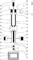
- FIG. 1 An embodiment of a washing machine according to the invention is shown.
- the washing machine is designed as a washing machine for laundry items.
- the washing machine has a treatment room 2, which comprises a washing drum 4 and a washing liquid container 6 designed as a tub, the washing drum 4 being rotatably arranged in the washing liquid container 6 in a manner known to those skilled in the art.
- the washing machine has a first reservoir 8 designed as a detergent canister for a first detergent 10 designed as a liquid detergent, a second reservoir 12 designed as a detergent canister for a second detergent 14 designed as a liquid detergent, and a third reservoir 16 designed as a chamber of a detergent dispenser 11 for a solid formed third detergent 18 and also formed as a chamber of the dispenser 11 fourth reservoir 13 for a fourth detergent 15 formed as a solid.
- the third and fourth detergents 15, 18 can each be designed, for example, as a tablet.
- the first reservoir 8 and the second reservoir 12 are each designed as a canister that can be removed from the washing machine.
- the dispenser drawer 11 is at least partially pullable out of a shaft of the washing machine, not shown, in a manner known to the person skilled in the art.
- the washing machine has a water supply system 19 with a water inlet 22 assigned to a water source 20 and a first water outlet 24 assigned to the first reservoir 8 and a second reservoir 12 second water outlet 26, a third water outlet 28 assigned to the third reservoir 16 and a fourth water outlet 29 assigned to the fourth reservoir 13, the first detergent 10, the second detergent 14, the third detergent 18 or the fourth detergent 15 in the treatment room 2 can be flushed in.
- the water supply system 19 is designed in such a way that the first detergent 10 in a first operating state of the water supply system 19, in which a first water path 30 connected to the water inlet 22 in a flow-conducting manner and a second water path 32 connected to the water inlet 22 in a flow-conducting manner, and a third with the water opening 22 Water inlet 22 flow-connected water path 33 are closed, and the second detergent 14 in a second operating state of the water supply system 19, in which the first water path 30 and the third water path 33 are closed and the second water path 32 is open, each in the manner of a water jet pump by means of the Water is sucked from the water source 20 out of the respective reservoir 8, 12 and can be conveyed with this water into the treatment room 2, whereby in a third operating state of the water supply system 19, in which the first and the second water path 30, 32 are open at the same time and the third water path 33 is closed, the third detergent 18 can be conveyed from the third reservoir 16 by means of the water from the water source 20 into the
- the third detergent 18 is in the third operating state of the water supply system 19 by means of the water from the water source 20 can be rinsed out of the third reservoir 16, namely the chamber of the dispenser drawer 11 assigned to the third detergent 18.
- the water supply system 19 has a first valve 34 in the first water path 30, a second valve 36 in the second water path 32 and in the third water path 33 has a third valve 37, the first, second and third valves 34, 36, 37 being designed to be controllable by means of a control, not shown, of the washing machine.
- the valves 34, 36, 37 are combined as one structural unit 38, for example a multiple solenoid valve.
- a flow constant 40, 42 are arranged in the first water path 30 and in the second water path 32.
- no flow stabilizer is arranged in the third waterway 33.
- Fig. 1 the water supply system 19 of the washing machine is shown in its first operating state.
- the first valve 34 is automatically opened by means of the control of the washing machine as a function of the previously selected washing program, and the second valve and the third valve 36, 37 are automatically closed.
- the first water path 30 is connected in a flow-conducting manner to the water inlet 22 of the water supply system 19, so that water from the water source 20, namely the fixed water connection, can flow into the first water path 30.
- the water flows in the first water path 30 in the direction of flow after the flow stabilizer 40 at a constant rate of 2 l / min.
- the first water path 30 is first passed through a hose 44, in order to then be guided in a hose 48 downstream over a free flow path 46.
- a hose 50 is connected in a flow-conducting manner to the hose 48, which in turn is connected in a flow-conducting manner to the first reservoir 8, in which the first detergent 10 is stored.
- the detergent 10 is made by means of the hose 50 in the manner of a water jet pump sucked in and conveyed with the water through the hose 48 and the first water outlet 24 formed on the hose 48 into the treatment room 2, namely into the washing liquid container 6.
- the first detergent 10 can be introduced directly into the treatment room 2 by means of the water from the water source 20 in the manner explained above. In the present exemplary embodiment, however, it is provided that the first detergent 10 is introduced into the treatment room 2 by means of the dispenser drawer 11.
- the first detergent 10 is first introduced by means of the water from the water source 20 into a chamber of the dispenser box 11 assigned to the first detergent 10, for example a chamber of the dispenser box 11 assigned to the main wash, before it is then conveyed from this chamber into the treatment room 2 becomes.
- another detergent for example a powder or tablet detergent, which is filled into the chamber assigned to the first detergent 10, by means of the water from the water source 20 from the dispenser 11 can be rinsed out and washed into the treatment room 2.
- the chamber of the induction box 11 assigned to the first detergent 10 can be rinsed out of the water source 20 by means of the water and thus cleaned after the first detergent 15 or the further detergent has been rinsed out.
- Fig. 2 shows the water supply system 19 of the washing machine in its second operating state.
- the conveyance of the second detergent 14 from the second reservoir 12 into the treatment room 2 works analogously to the above-described conveyance of the first detergent 10 from the first reservoir 8 into the treatment room 2.
- the first and third valves 34, 37 are automatically closed by means of the control of the washing machine in dependence on the previously selected washing program and the second valve 36 is automatically opened.
- the second water path 32 is connected in a flow-conducting manner to the water inlet 22 of the water supply system 19, so that water from the water source 20, namely the fixed water connection, can flow into the second water path 32.
- the water flows in the second water path 32 in the direction of flow after the flow stabilizer 42 at a constant rate of 2 l / min.
- the second water path 32 is first passed through a hose 52, in order to then be guided in a hose 54 downstream over the free flow path 46.
- a hose 56 is connected in a flow-conducting manner to the hose 54, which hose is in turn connected to the second reservoir 12, in which the second detergent 14 is stored, in a flow-conducting manner.
- the second detergent 14 is sucked in by means of the hose 56 in the manner of a water jet pump and with the water through the hose 54 and the second water outlet 26 formed on the hose 54 into the treatment room 2, namely promoted in the washing liquid container 6.
- the second detergent 14 can be introduced directly into the treatment room 2 by means of the water from the water source 20 in the manner explained above.
- the second detergent 14 is introduced into the treatment room 2 by means of the induction box 11.
- the second detergent 14 is first introduced by means of the water from the water source 20 into a chamber of the dispenser box 11 assigned to the second detergent 14, for example a chamber of the dispenser box 11 assigned to the prewash, before it is subsequently conveyed from this chamber into the treatment room 2 becomes.
- a further detergent for example a powdery or tablet-type detergent, which is filled into the chamber assigned to the second detergent 14, in the same way, by means of the water from the water source 20 from the dispenser 11 can be rinsed out and washed into the treatment room 2.
- a further detergent for example a powdery or tablet-type detergent, which is filled into the chamber assigned to the second detergent 14, in the same way, by means of the water from the water source 20 from the dispenser 11 can be rinsed out and washed into the treatment room 2.
- the second valve 36 it is only necessary to control the second valve 36 in such a way that only water is conveyed from the water source 20 into the dispenser 11. This is possible by a correspondingly quick activation of the second valve 36, which is designed as a solenoid valve.
- the chamber of the dispenser drawer 11 associated with the second detergent 14 can be rinsed out of the water source 20 by means of the water and thus cleaned after the second detergent 14 or the further detergent has been rinsed out.
- the washing program selected in advance provides for the third washing agent 18 to be conveyed from the third reservoir 16 into the treatment room 2
- the first and second valves 34, 36 are opened simultaneously by means of the control, while the third valve 37 is closed .
- the first waterway 30 and the second water path 32 is connected to the water inlet 22 of the water supply system 19 in a flow-conducting manner, so that water from the water source 20, namely the fixed water connection, can flow into the first water path 30 and the second water path 32 simultaneously.
- Fig. 3 The flow rate of 10 l / min. in the water inlet 22 in the flow direction in front of the flow stabilizers 40, 42 to 2 l / min.
- the water flows in the first and second water paths 30, 32 in the direction of flow after the flow stabilizers 40, 42 at a constant rate of 2 l / min.
- the first and the second water path 30, 32 are each first led through a hose 44, 52.
- the chamber of the induction box 11 assigned to the third detergent 18 can be rinsed from the water source 20 by means of the water and thus cleaned after the third detergent 18 or the further detergent has been rinsed out of this chamber, i.e. the third reservoir 16 .
- the first and the second valve 34, 36 are automatically closed by means of the control of the washing machine as a function of the previously selected washing program and the third valve 37 is opened automatically.
- the third water path 33 is connected in a flow-conducting manner to the water inlet 22 of the water supply system 19, so that water from the water source 20, namely the fixed water connection, can flow into the third water path 33.
- the flow rate becomes 10 l / min. not reduced, so the flow rate of 10 l / min. remains the same along the third waterway 33.
- the third water path 33 is passed through a hose 53.
- the water flows at a flow rate of 10 l / min. introduced into the fourth reservoir 13, namely a chamber of the dispenser drawer 11 assigned to the fourth detergent 15.
- the fourth detergent 15 is rinsed out of the fourth reservoir 13 by means of the water and conveyed via a flow connection, not shown, into the treatment room 2, namely into the washing liquid container 6.
- the chamber of the induction box 11 assigned to the fourth detergent 15 can be rinsed from the water source 20 by means of the water after the fourth detergent 15 or further detergent has been rinsed out of this chamber, that is to say the fourth reservoir 13, and thus cleaned .
- the invention is not limited to the present exemplary embodiment.
- the third detergent in the third operating state of the water supply system from the third reservoir and / or the fourth detergent in the fourth operating state of the water supply system from the fourth reservoir in the manner of a water jet pump by means of the water drawn in from the water source and with this water are conveyable to the treatment room.
- This embodiment which differs from the present exemplary embodiment, is shown in FIGS 1 to 4 not shown, but is explained below as an example for the third detergent.
- the following would then be as follows: in the third operating state of the water supply system 19, the first and the second valves 34, 36 are automatically opened by means of the control of the washing machine as a function of the previously selected washing program, while the third valve 37 is closed. Accordingly, the first water path 30 and the second water path 32 are connected in a flow-conducting manner to the water inlet 22 of the water supply system 19, so that water from the water source 20, namely the fixed water connection, can flow into the first water path 30 and the second water path 32 simultaneously.
- the water flows in the first and second water paths 30, 32 in the direction of flow after the flow stabilizers 40, 42 at a constant rate of 2 l / min.
- the first and the second water path 30, 32 are each first led through a hose 44, 52.
- a hose (not shown) is connected in a flow-conducting manner, which in turn is connected in a flow-conducting manner to the third reservoir 16, in which the third detergent 18 is stored.
- the third detergent 18 is sucked in by means of the hose, not shown, analogously to the first and the second detergent 10, 14 of the present exemplary embodiment, in the manner of a water jet pump and with the water through the hose 58 and on the third water outlet 28 formed in the hose 58 into the treatment room 2, namely into the washing liquid container 6.
- the washing machine according to the invention in another embodiment of the washing machine according to the invention it can be provided that, alternatively or in addition to the simultaneous opening of the first and the second valve when the third valve is closed, and thus the simultaneous opening of the first and the second water path, in a further operating state of the water supply system the washing machine according to the invention, the first and the third valve are simultaneously open when the second valve is closed or the second and the third valve are simultaneously open when the first valve is closed. Accordingly, even more operating states than those explained on the basis of the present exemplary embodiment can be Realize operating states of the water supply system and thus the washing machine according to the invention.
- a flushing of only water from the water source into the treatment room can be formed, for example, by bypassing the chamber of the flushing box assigned to the fourth detergent. The bypass of this chamber would then be connected to the treatment room in a flow-conducting manner. In this way it is also possible to flush fresh water into the sight glass.
- the first and second detergents can be, for example, a washing solution, an emulsion or a dispersion.
- the third and / or fourth detergent can be in the form of a washing solution, an emulsion or a dispersion. If the third and / or fourth detergent is rinsed out of the third and / or fourth reservoir, it can also be either a washing solution, an emulsion, a dispersion or a solid.
- the solid can be freely selected after it has been assembled within a wide range.
- the solid can be in the form of a powder, a pressed tablet or the like. In connection with the water from the water source, the so-called wash liquor is then obtained.
- washing machine is to be interpreted broadly and includes any type of washing machine for cleaning a good to be cleaned.
- the washing machine according to the invention can be, for example, a washing machine for laundry or a washing machine for dishes and cutlery, that is to say a dishwasher.
- Other types of washing machines for example for special applications in hospitals or the like, are also conceivable.
- the washing machine according to the invention can be used advantageously both in the household and in professional use, that is to say in trade. Accordingly, the term “treatment room” should be interpreted broadly.
- the treatment room comprises, for example, a washing liquid container designed as a tub and a laundry drum which is rotatably arranged in the tub.
- the treatment room can be designed as the room for the dishes and cutlery.
Landscapes
- Engineering & Computer Science (AREA)
- Textile Engineering (AREA)
- Detail Structures Of Washing Machines And Dryers (AREA)
Applications Claiming Priority (1)
| Application Number | Priority Date | Filing Date | Title |
|---|---|---|---|
| DE102018124453.3A DE102018124453A1 (de) | 2018-10-04 | 2018-10-04 | Waschmaschine |
Publications (1)
| Publication Number | Publication Date |
|---|---|
| EP3632289A1 true EP3632289A1 (fr) | 2020-04-08 |
Family
ID=67953689
Family Applications (1)
| Application Number | Title | Priority Date | Filing Date |
|---|---|---|---|
| EP19197073.0A Withdrawn EP3632289A1 (fr) | 2018-10-04 | 2019-09-12 | Machine à laver |
Country Status (2)
| Country | Link |
|---|---|
| EP (1) | EP3632289A1 (fr) |
| DE (1) | DE102018124453A1 (fr) |
Citations (5)
| Publication number | Priority date | Publication date | Assignee | Title |
|---|---|---|---|---|
| EP0244900A2 (fr) * | 1986-04-30 | 1987-11-11 | Whirlpool International B.V. | Tiroir à détergents pour machines à laver avec conduits d'amenée d'eau non intégrés |
| EP0725182A1 (fr) * | 1995-02-03 | 1996-08-07 | Bosch-Siemens HausgerÀ¤te GmbH | Dispositif d'alimentation en eau pour appareil domestique à circulation d'eau |
| WO2004106617A1 (fr) * | 2003-05-28 | 2004-12-09 | Electrolux Home Products Corporation N.V. | Machine a laver les vetements a agencement integre de vannes electromagnetiques |
| WO2015074688A1 (fr) * | 2013-11-20 | 2015-05-28 | Electrolux Appliances Aktiebolag | Machine à laver le linge à tiroir à détergent comprenant un tableau de commande |
| EP2902540A1 (fr) * | 2014-01-30 | 2015-08-05 | Candy S.p.A. | Machine à laver le linge |
Family Cites Families (1)
| Publication number | Priority date | Publication date | Assignee | Title |
|---|---|---|---|---|
| DE10116832B4 (de) * | 2001-04-04 | 2006-09-21 | BSH Bosch und Siemens Hausgeräte GmbH | Maschine in Form einer Wäsche-Waschmaschine oder Geschirrspülmaschine |
-
2018
- 2018-10-04 DE DE102018124453.3A patent/DE102018124453A1/de not_active Withdrawn
-
2019
- 2019-09-12 EP EP19197073.0A patent/EP3632289A1/fr not_active Withdrawn
Patent Citations (5)
| Publication number | Priority date | Publication date | Assignee | Title |
|---|---|---|---|---|
| EP0244900A2 (fr) * | 1986-04-30 | 1987-11-11 | Whirlpool International B.V. | Tiroir à détergents pour machines à laver avec conduits d'amenée d'eau non intégrés |
| EP0725182A1 (fr) * | 1995-02-03 | 1996-08-07 | Bosch-Siemens HausgerÀ¤te GmbH | Dispositif d'alimentation en eau pour appareil domestique à circulation d'eau |
| WO2004106617A1 (fr) * | 2003-05-28 | 2004-12-09 | Electrolux Home Products Corporation N.V. | Machine a laver les vetements a agencement integre de vannes electromagnetiques |
| WO2015074688A1 (fr) * | 2013-11-20 | 2015-05-28 | Electrolux Appliances Aktiebolag | Machine à laver le linge à tiroir à détergent comprenant un tableau de commande |
| EP2902540A1 (fr) * | 2014-01-30 | 2015-08-05 | Candy S.p.A. | Machine à laver le linge |
Also Published As
| Publication number | Publication date |
|---|---|
| DE102018124453A1 (de) | 2020-04-09 |
Similar Documents
| Publication | Publication Date | Title |
|---|---|---|
| DE60013345T2 (de) | Geschirrspülmaschine mit pulsierenden Wasserstrahlen | |
| EP0725182A1 (fr) | Dispositif d'alimentation en eau pour appareil domestique à circulation d'eau | |
| DE102007037883A1 (de) | Mehrfachzugabeventil für eine Anlage zum Dosieren flüssigen oder pastösen Waschhilfsmitteln und Verfahren zum Betreiben des Mehrfachzugabeventils | |
| DE202014105113U1 (de) | Spülarmsystem für Spülmaschine | |
| DE1913868B2 (de) | Maschine zum Waschen von Textil, Geschirr o.dgl | |
| DE102017217801A1 (de) | Wasserführendes Haushaltsgerät und Verfahren zum Betreiben eines wasserführenden Haushaltsgeräts | |
| DE10024014C2 (de) | Dosiervorrichtung für flüssiges Spülmittel | |
| DE102011083297B3 (de) | Wasserführendes Haushaltsgerät mit einer Dosierpumpe | |
| DE102016120534B3 (de) | Wasserzuführungs- und Waschmitteleinspülsystem für eine Waschmaschine | |
| DE102020116870A1 (de) | Einrichtung zum Zuführen von Behandlungsmittel für eine Waschmaschine und Waschmaschine | |
| EP3632288A1 (fr) | Machine à laver | |
| EP2896342B2 (fr) | Réglette de répartition | |
| EP3632289A1 (fr) | Machine à laver | |
| CH674134A5 (fr) | ||
| DE102006012283B3 (de) | Waschmaschine mit externer Waschmittelbeschickung | |
| EP3633095A1 (fr) | Lave-linge avec un système pour l'alimentation d'eau | |
| DE102020204010A1 (de) | Haushalts-Geschirrspülmaschine | |
| EP2641619B1 (fr) | Automate de nettoyage et de désinfection | |
| DE102016122076A1 (de) | Geschirrspülmaschine mit einem Sprüharmsystem, das eine Lageranordnung aufweist | |
| DE102019135161A1 (de) | Waschmaschine | |
| EP1767135A1 (fr) | Lave-vaisselle avec dispositif de distribution de l'eau. | |
| EP3186430A1 (fr) | Dispositif de raccord de fluide pour appareil ménager et appareil ménager équipé de celui-ci | |
| DE2542393C2 (de) | Wasserverteilvorrichtung für automatische Wasch- oder Geschirrspülmaschinen | |
| DE10223741B4 (de) | Verteiler für dosierte Mengen eines flüssigen Additivs, insbesondere für die Verwendung in einer Geschirrspülmaschine für die professionelle Anwendung | |
| DE60021376T2 (de) | Eine unterdruckeinheit und ein unterdrucktoilettensystem mit einer solchen einheit |
Legal Events
| Date | Code | Title | Description |
|---|---|---|---|
| PUAI | Public reference made under article 153(3) epc to a published international application that has entered the european phase |
Free format text: ORIGINAL CODE: 0009012 |
|
| STAA | Information on the status of an ep patent application or granted ep patent |
Free format text: STATUS: THE APPLICATION HAS BEEN PUBLISHED |
|
| AK | Designated contracting states |
Kind code of ref document: A1 Designated state(s): AL AT BE BG CH CY CZ DE DK EE ES FI FR GB GR HR HU IE IS IT LI LT LU LV MC MK MT NL NO PL PT RO RS SE SI SK SM TR |
|
| AX | Request for extension of the european patent |
Extension state: BA ME |
|
| 18D | Application deemed to be withdrawn |
Effective date: 20201009 |