EP3632313B1 - Adaptateur - Google Patents
Adaptateur Download PDFInfo
- Publication number
- EP3632313B1 EP3632313B1 EP18805423.3A EP18805423A EP3632313B1 EP 3632313 B1 EP3632313 B1 EP 3632313B1 EP 18805423 A EP18805423 A EP 18805423A EP 3632313 B1 EP3632313 B1 EP 3632313B1
- Authority
- EP
- European Patent Office
- Prior art keywords
- adapter
- blood sampling
- male screw
- blood
- attachment
- Prior art date
- Legal status (The legal status is an assumption and is not a legal conclusion. Google has not performed a legal analysis and makes no representation as to the accuracy of the status listed.)
- Active
Links
Images

Classifications
-
- A—HUMAN NECESSITIES
- A61—MEDICAL OR VETERINARY SCIENCE; HYGIENE
- A61B—DIAGNOSIS; SURGERY; IDENTIFICATION
- A61B5/00—Measuring for diagnostic purposes; Identification of persons
- A61B5/15—Devices for taking samples of blood
- A61B5/153—Devices specially adapted for taking samples of venous or arterial blood, e.g. with syringes
- A61B5/154—Devices using pre-evacuated means
-
- A—HUMAN NECESSITIES
- A61—MEDICAL OR VETERINARY SCIENCE; HYGIENE
- A61B—DIAGNOSIS; SURGERY; IDENTIFICATION
- A61B5/00—Measuring for diagnostic purposes; Identification of persons
- A61B5/15—Devices for taking samples of blood
- A61B5/150007—Details
- A61B5/150015—Source of blood
- A61B5/15003—Source of blood for venous or arterial blood
-
- A—HUMAN NECESSITIES
- A61—MEDICAL OR VETERINARY SCIENCE; HYGIENE
- A61B—DIAGNOSIS; SURGERY; IDENTIFICATION
- A61B5/00—Measuring for diagnostic purposes; Identification of persons
- A61B5/15—Devices for taking samples of blood
- A61B5/150007—Details
- A61B5/150732—Needle holders, for instance for holding the needle by the hub, used for example with double-ended needle and pre-evacuated tube
-
- A—HUMAN NECESSITIES
- A61—MEDICAL OR VETERINARY SCIENCE; HYGIENE
- A61B—DIAGNOSIS; SURGERY; IDENTIFICATION
- A61B5/00—Measuring for diagnostic purposes; Identification of persons
- A61B5/15—Devices for taking samples of blood
- A61B5/150992—Blood sampling from a fluid line external to a patient, such as a catheter line, combined with an infusion line; Blood sampling from indwelling needle sets, e.g. sealable ports, luer couplings or valves
-
- A—HUMAN NECESSITIES
- A61—MEDICAL OR VETERINARY SCIENCE; HYGIENE
- A61B—DIAGNOSIS; SURGERY; IDENTIFICATION
- A61B5/00—Measuring for diagnostic purposes; Identification of persons
- A61B5/15—Devices for taking samples of blood
- A61B5/150007—Details
- A61B5/150206—Construction or design features not otherwise provided for; manufacturing or production; packages; sterilisation of piercing element, piercing device or sampling device
- A61B5/150305—Packages specially adapted for piercing devices or blood sampling devices
Definitions
- the present invention relates to an adapter.
- a blood sampling kit has been used for collecting blood sample for a blood test and the like.
- the blood sampling kit collects blood from a human body by a blood sampler, and the collected blood sample is reserved in a vacuum blood collection tube attached to a blood sampling holder.
- Such blood sampling kit includes the blood sampler, an adapter to which the blood sampler is connected, the blood sampling holder to which the adapter is attached, and the vacuum blood collection tube.
- the adapter for the attachment of the adapter to the blood sampling holder, there are a type in which a male screw formed in the adapter is screwed to a female screw formed in the blood sampling holder and a type in which a locking member provided at the blood sampling holder is fit and engaged to a groove part formed in the adapter.
- An adapter applicable to both of the screw type and the engagement type has been proposed (for example, refer to Patent Document 1).
- Patent Literature 1 Japanese Patent Application Laid-Open No. 2003-245267 ).
- the male screw is extended from a substantially cylindrical body part in the base end direction, and an annular groove part is formed at a root of the male screw.
- the adapter is attached to the blood sampling holder by screwing the male screw of the adapter to the female screw formed at the attachment part of the blood sampling holder in the case where the blood sampling holder is a screw type, while the adapter is attached to the blood sampling holder by engaging the locking member provided at the attachment part of the blood sampling holder to the annular groove part of the adapter in the case where the blood sampling holder is an engagement type.
- the blood sampling needle Since the blood sampling needle is inserted in the human body, it is preferable that the blood sampling needle is maintained in a fixed state during the blood sampling.
- the adapter since only the locking member of the blood sampling holder is engaged to the annular groove part.
- an object of the present invention to provide an adapter capable of restricting the rotation of the adapter with respect to the engagement type blood sampling holder, even with an adapter corresponding to both types of blood sampling holder such as the screw type and the engagement type.
- the adapter according to the present invention is an adapter attached to an attachment part in which a through-hole is formed and provided at a bottom part of a blood sampling holder which is a bottomed hollow cylinder,
- the protruding part is inserted into the through-hole of the attachment part of the blood sampling holder, and the flange part is abut to the leading end surface of the attachment part.
- the protruding part since the protruding part includes the male screw part, it is possible to screw the male screw part to the female screw part of the blood sampling holder.
- the male screw part is formed with a cut-out part closer to the base end side than the leading end of the male screw part, it is able to engage the protruding part by fitting the locking part urged by the biasing member to the cut-out part. Furthermore, since the cut-out part is formed at a part of the male screw part in the peripheral direction, when the locking member is fit to the cut-out part, the movement of the locking member is restricted by the thread ridge of the male screw part in the periphery of the cut-out part. Therefore, the rotation of the protruding part with respect to the attachment part is restrained.
- the cut-out part is a recessed part formed as a groove shape along an axis of the protruding part.
- the recessed part having a groove shape along the axis of the protruding part, since the locking member is introduced into the recessed part, the interval between the locking member and the thread ridge of the male screw part in the periphery of the recessed part is decreased, thereby enabling to prevent the so-called wobble of the protruding part in the rotating direction and the adapter can be completely prevented from rotating.
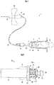
- a blood sampling kit 1 of an embodiment of the present invention is explained in details. As shown in FIG. 1 , the blood sampling kit 1 collects blood from human body by a blood sampler 40 (hereinafter referred to as a butterfly needle), and the collected blood is reserved in a vacuum blood collection tube 2 attached to a blood sampling holder 3.
- a blood sampler 40 hereinafter referred to as a butterfly needle
- the blood sampling kit 1 includes a blood sampling holder 3 which is a bottomed hollow cylinder to which the vacuum blood collection tube 2 for storing the blood is attached, an adapter 20 attached to an attachment part 4 provided at a bottom part 7 of the blood sampling holder 3, a connector 30 connected to the adapter 20, a flexible tube 31 extending from the connector 30, and a butterfly needle 40 connected to the flexible tube 31.
- the adapter 20 is provided with a needle tube 32 at the needle base 25.
- the needle tube 32 is covered by a rubber sleeve (not illustrated) for protecting the needle tube 32 until the adapter 20 is attached to the blood sampling holder 3.
- a rubber sleeve (not illustrated) for protecting the needle tube 32 until the adapter 20 is attached to the blood sampling holder 3.
- the butterfly needle 40 includes a hub 42 for supporting a needle tube 41 having a sharp front end and a pair of butterfly members 43 which are fit onto the hub 42.
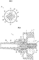
- the adapter 20 includes: a hollow body part 21 which is connectable to the butterfly needle 40 (refer to FIG. 1 ) via the connector 30 (refer to FIG. 1 ) and through which the sampled blood flows; a flange part 22 which is provided at a base end side of the body part 21 and which abuts the leading end surface 8 of the attachment part 4 (refer to FIG. 4 ); and a cylindrical protruding part 23 which extends from the flange part 22 in a direction opposite to the body part 21 and which is inserted into the through-hole (refer to FIG. 4 ) of the attachment part 4.
- the body part 21 is a lure tapered shape in which the connection opening is a round shape having a diameter of 4 mm and tapered by 6/100.
- the body part 21 is a lure tapered shape, it may be a cylindrical shape or any tapered shape.
- a rubber sleeve fitting part 24 is formed to which the rubber sleeve is fitted, and at the leading end side of the rubber sleeve fitting part 24, a tapered needle base 25 is provided for guiding the protruding part 23 when inserting the protruding part 23 into the attachment part 4.
- a cut-out part 26 having a groove shape along the axis of the protruding part 23 is formed at the outer periphery of the protruding part 23.
- a male screw part 27 is formed in the outer periphery of the protruding part 23, and a cut-out part 26 is formed by cutting out a portion of the male screw part 27 in a peripheral direction closer to the base end side (flange part side) than the leading end.
- the cut-out part 26 may cut out not only less than a half but also half or more of the outer periphery of the protruding part 23 if there is a male screw part 27 in at least a part of the peripheral direction of the outer periphery of the protruding part 23.
- the cut-out part 26 may have any shape as long as the locking member is able to fit and engage such as a cross-sectional V shape, a round hole to which the pin fits, or the like.
- the cut-out part 26 is a plurality of recessed parts forming a groove along the axis of the protruding part 23.
- the cut-out part 26 will be referred to as the recessed part 26.
- the recessed part 26 forming a groove along the axis is formed from the end portion of the flange part 22.
- the recessed part 26 forming the groove along the axis may be formed on the way in the axis direction of the male screw part 27, since the locking member 11 which engages the recessed part 26 (refer to FIG. 5A and FIG. 5B ) is restricted from moving in the axis direction by the ridge of the male screw part 27, thereby preventing the adapter 20 from coming off from the blood sampling holder 3.
- Two ribs 28 are formed between the body part 21 and the flange part 22. Although two ribs 28 are formed in the present embodiment, it is not limited as such, and the ribs may be four or the like as long as the connector 30 can be guided when connecting the connector 30 to the adapter 20 (refer to FIG. 1 ). Furthermore, if the body part 21 and the flange part 22 have appropriate strength, the rib 28 may be omitted.
- the adapter 20 is formed with a through-hole 29 in which the needle tube 32 is inserted.
- the recessed part 26 forms a groove shape which is recessed so as to curve to the axis side.
- the recessed part 26 is formed to have a groove shape so as to curve to the axis side.
- the bottom of the recessed part 26 may be a plane surface as long as it is recessed with respect to the screw head of the male screw part 27 and the recessed part 26 can be engaged by the locking member 11 (refer to FIG. 5A and FIG. 5B ).
- the recessed part 26 is provided at positions equally dividing the outer periphery of the protruding part 23 into four. Although four recessed parts 26 are formed in the male screw part 27 in the present embodiment, the recessed part 26 may be plural such as two, or only one may be formed. Moreover, in the case of providing a plurality of recessed parts 26, they may be provided at unequal positions rather than positions which equally divide the outer periphery of the protruding part 23.
- the blood sampling holder 3 includes: a holder body part 5 which is a bottomed hollow cylinder; and an attachment part 4 provided at a bottom part 7 of the holder body part 5 and formed with a through-hole 9.
- the attachment part 4 is formed with a female screw part 6 at a portion where the adapter 20 is inserted.
- the protruding part 23 of the adapter is attached to the attachment part 4 by screwing the male screw part 27 of the adapter 20 to the female screw part 6, and abutting the flange part 22 to the leading end surface 8 of the attachment part 4.
- the adapter 20 in order to obtain the necessary fitting strength or more, quite a number of screw threads will be necessary, requiring the length of the screw part of the male screw part 27 to have a certain length.
- an annular groove is formed from an end surface of the body part, and is formed so as to add the male screw from the leading end side of the annular groove. Therefore, the length from the end surface of the body part to the leading end of the male screw becomes long. Moreover, in the case where the female screw of the blood sampling holder side exists only at a position corresponding to the annular groove of the adapter, it is not able to completely fasten the male screw of the adapter, and the connecting is not possible.
- the male screw part 27 is formed from the end surface of the flange part 22, it is possible to make the length from the end surface of the flange part 22 to the leading end of the male screw part 27 shorter compared to the conventional technology. Therefore, the adapter 20 of the present invention is able to be applied to both of the screw type and the engagement type blood sampling holders, and also able to shorten the length of the adapter 20. Moreover, since the male screw part 27 is formed from the end surface of the flange part 22, even if the female screw part 6 of the blood sampling holder 3 side is formed only at a position corresponding to the recessed part 26, the male screw part 27 can be completely fastened.
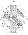
- the blood sampling holder 3 includes a holder body part 5 which is a bottomed hollow cylinder and an attachment part 4 provided at a bottom part 7 of the holder body part 5.
- the attachment part 4 is explained by a diagram expressed schematically.
- the attachment part 4 includes: a sill 13 formed so as to protrude outward of the blood sampling holder 3 from the bottom part 7; a guide hole 14 formed in the sill 13 and which movably supports the locking members 11; a pair of locking members 11 which are inserted to the guide hole 14 and which are provided to be movable in a diameter direction and fit to the recessed part 26 to lock the protruding part 23; and a biasing member 12 which energizes each claw part 16 of the pair of locking members 11 to the axis side.
- the locking member 11 includes: a locking body part 15 which is movably supported by the guide hole 14; the claw part 16 formed at the end of the locking body part 15 and fits the recessed part 26; a detouring member 17 which is extendedly provided so as to detour the sill 13 from the opposite side of the locking body part 15 from the claw part 16, and which is folded back in a U-shape in a side view.
- the biasing member 12 is a compression spring supported by a spring seat 18 provided at the sill 13. By urging a part of the detouring member 17 positioned at the opposite side of the claw part 16 with respect to the axis of the protruding part 23, the claw part 16 is biased to the axis side.
- a needle tube 32 is provided at the needle base 25 of the adapter 20, and the needle tube 32 is covered by a rubber sleeve 33.
- the protruding part 23 of the adapter 20 is inserted into the through-hole 9 of the attachment part 4 of the blood sampling holder 3 as indicated by arrow (1).
- the pair of locking members 11 are pushed open as indicated by arrows (2) by the rubber sleeve 33 and the male screw part 27 of the protruding part 23.
- the flange part 22 abuts the leading end surface 8 of the attachment part 4.
- the claw part 16 of the locking member 11 which is biased to the axis side by the biasing member 12 fits the recessed part 26 and locks the protruding part 23.
- the male screw part 27 since the ridge of the male screw part 27 is at the leading end side than the claw part 16 of the locking member 11, the movement of the claw part 16 of the locking member 11 to the axis direction is restricted serving as a stopper, thereby enabling to prevent the adapter 20 from falling out from the blood sampling holder 3.
- the attachment part 4 includes: a locking member 11 which is provided movable in the diameter direction and fits the recessed part 26 (cut-out part) to lock the protruding part 23; and a biasing member 12 which urges the locking member 11 to the axis side.
- the locking member 11 urged by the biasing member 12 fits to the cut-out part 26 of the protruding part 23 inserted into the attachment part 4, and contacts the ridge of the male screw part 27, thereby locking the protruding part 23 and restricting the rotation of the protruding part 23.
- the recessed part 26 is formed at a part of the male screw part 27 in the peripheral direction, when the claw part 16 of the locking member 11 fits to the recessed part 26, the movement of the locking member 11 is relatively restricted by the ridge of the male screw part 27 in the circumference of the recessed part 26. Therefore, the rotation of the protruding part 23 with respect to the attachment part 4 is restrained.
- the recessed part 26 is a groove along the axis of the protruding part 23, by guiding the claw part 16 of the locking member 11 by the recessed part 26, the gap between the ridge of the male screw part 27 in the circumference of the recessed part 26 and the claw part 16 of the locking member 11 becomes small, thereby eliminating the so-called rattling of the protruding part 23 in the rotating direction and preventing the adapter from rotating completely.
- the recessed part 26 is recessed so as to smoothly curve to the axis side.
- the part of the claw part 16 of the locking member 11 which abuts the recessed part 26 is formed as a corner part 19.
- this corner part 19 may be formed as a guiding curved surface part having a shape corresponding along the curved surface of the recessed part 26.
- the corner part 19 As the guiding curved surface part, when inserting the protruding part 23 of the adapter 20 into the attachment part 4, even if the claw part 16 does not fit to the recessed part 26 and rides onto the ridge of the male screw part 27, since the locking member 11 is biased to the axis side by the biasing member 12, the curved surface of the guiding curved surface part 19 slides the outer periphery of the ridge (crest of the thread)of the male screw part 27 to rotate the protruding part 23 as indicated by arrow (4), and the guiding curved surface part 19 fits to the recessed part 26.
- the guiding curved surface part 19 it is able to guide the recessed part 26 of the protruding part 23 to fit to the guiding curved surface part 19. As a result, it is able to restrict the rotation of the adapter 20 with respect to the blood sampling holder 3.
- the locking member 11 is provided with one locking member body part 15 and two claw parts 16, and has a U-shape in planar view.
- two such locking members 11 having a U-shape in planar view as a pair of locking members 11, it is able to sandwich the protruding part 23 thereby enabling to lock four recessed parts 26.
- the adapter 20 of the present invention can be applied to both of the screw type and engagement type blood sampling holders 3, and it is able to restrict the rotation of the adapter 20 also in the case of using the engagement type blood sampling holder 3.
- the biasing member 12 and the locking member 11 are provided as separate elements, it is possible to integrally provide them by a resin component having elasticity.
- the engagement type attachment part 4 is not limited to the manner shown in FIG. 5A and FIG. 5B , and it may be any configuration as long as it can lock the cut-out part 26 (recessed part) of the adapter 20.
- the blood sampler 40 is a butterfly needle, it is not limited as such, and it may be a single needle tube as long as it is capable of blood sampling.
- 3 ... blood sampling holder; 4 ... attachment part; 7 ... bottom part; 8 ... leading end surface; 9 ... through-hole; 20 ... adapter; 21 ... body part; 22 ...flange part; 23 ... protruding part; 26 ... cut-out part (recessed part); 27 ... male screw part; and 40 ... blood sampler (butterfly needle, needle tube).
Landscapes
- Health & Medical Sciences (AREA)
- Life Sciences & Earth Sciences (AREA)
- Heart & Thoracic Surgery (AREA)
- Medical Informatics (AREA)
- Biophysics (AREA)
- Pathology (AREA)
- Engineering & Computer Science (AREA)
- Biomedical Technology (AREA)
- Hematology (AREA)
- Physics & Mathematics (AREA)
- Molecular Biology (AREA)
- Surgery (AREA)
- Animal Behavior & Ethology (AREA)
- General Health & Medical Sciences (AREA)
- Public Health (AREA)
- Veterinary Medicine (AREA)
- Measurement Of The Respiration, Hearing Ability, Form, And Blood Characteristics Of Living Organisms (AREA)
- Sampling And Sample Adjustment (AREA)
Claims (2)
- Adaptateur fixé à une partie de fixation dans laquelle un trou traversant est formé et qui est disposé au niveau d'une partie fond d'un porte-prélèvements de sang qui est un cylindre creux à fond,dans lequel l'adaptateur comprend : une partie corps creux qui peut être reliée à un dispositif de prélèvement de sang pour prélever du sang d'un corps humain et à travers laquelle s'écoule le sang prélevé ; une partie bride qui est disposée au niveau d'un côté d'extrémité de base de la partie corps et qui vient en butée contre la surface d'extrémité avant de la partie de fixation ; et une partie saillante cylindrique qui s'étend à partir de la partie bride dans une direction opposée à la partie corps et qui est insérée dans le trou traversant de la partie de fixation, etau niveau d'une périphérie externe de la partie saillante, une partie filetage mâle est formée à partir du côté de la partie bride, caractérisé en ce queune partie découpée est formée par découpe d'une portion dans une direction périphérique, plus proche d'un côté d'extrémité de base que d'une extrémité avant, de la partie filetage mâle.
- Adaptateur selon la revendication 1, dans lequel la partie découpée est une partie encastrée formée sous la forme d'un sillon le long d'un axe de la partie saillante.
Applications Claiming Priority (2)
| Application Number | Priority Date | Filing Date | Title |
|---|---|---|---|
| JP2017104568A JP6792789B2 (ja) | 2017-05-26 | 2017-05-26 | アダプター |
| PCT/JP2018/005338 WO2018216272A1 (fr) | 2017-05-26 | 2018-02-15 | Adaptateur |
Publications (3)
| Publication Number | Publication Date |
|---|---|
| EP3632313A1 EP3632313A1 (fr) | 2020-04-08 |
| EP3632313A4 EP3632313A4 (fr) | 2021-05-19 |
| EP3632313B1 true EP3632313B1 (fr) | 2022-07-06 |
Family
ID=64395472
Family Applications (1)
| Application Number | Title | Priority Date | Filing Date |
|---|---|---|---|
| EP18805423.3A Active EP3632313B1 (fr) | 2017-05-26 | 2018-02-15 | Adaptateur |
Country Status (6)
| Country | Link |
|---|---|
| EP (1) | EP3632313B1 (fr) |
| JP (1) | JP6792789B2 (fr) |
| MY (1) | MY197426A (fr) |
| SG (1) | SG11201910135VA (fr) |
| TW (1) | TWI761518B (fr) |
| WO (1) | WO2018216272A1 (fr) |
Families Citing this family (2)
| Publication number | Priority date | Publication date | Assignee | Title |
|---|---|---|---|---|
| JP7530548B2 (ja) * | 2019-05-28 | 2024-08-08 | 株式会社トップ | 採血用ホルダ |
| JP7545627B2 (ja) * | 2019-06-13 | 2024-09-05 | 株式会社トップ | 採血管ホルダー及び採血キット |
Family Cites Families (6)
| Publication number | Priority date | Publication date | Assignee | Title |
|---|---|---|---|---|
| JPS5045091U (fr) * | 1973-08-24 | 1975-05-07 | ||
| JPH0234489Y2 (fr) * | 1985-01-21 | 1990-09-17 | ||
| JP3777595B2 (ja) * | 2002-02-25 | 2006-05-24 | ニプロ株式会社 | 採血針 |
| US20050273019A1 (en) * | 2004-06-02 | 2005-12-08 | Becton, Dickinson And Company | Blood collection set with venting mechanism |
| US9814870B2 (en) * | 2010-08-17 | 2017-11-14 | Becton, Dickinson And Company | Non-luer connectors |
| WO2014029421A1 (fr) * | 2012-08-21 | 2014-02-27 | Optomeditech Oy | Ensemble aiguille de prélèvement sanguin comportant une source lumineuse |
-
2017
- 2017-05-26 JP JP2017104568A patent/JP6792789B2/ja active Active
-
2018
- 2018-02-15 SG SG11201910135V patent/SG11201910135VA/en unknown
- 2018-02-15 MY MYPI2019006096A patent/MY197426A/en unknown
- 2018-02-15 EP EP18805423.3A patent/EP3632313B1/fr active Active
- 2018-02-15 WO PCT/JP2018/005338 patent/WO2018216272A1/fr not_active Ceased
- 2018-05-24 TW TW107117682A patent/TWI761518B/zh active
Also Published As
| Publication number | Publication date |
|---|---|
| EP3632313A4 (fr) | 2021-05-19 |
| EP3632313A1 (fr) | 2020-04-08 |
| WO2018216272A1 (fr) | 2018-11-29 |
| JP2018198740A (ja) | 2018-12-20 |
| JP6792789B2 (ja) | 2020-12-02 |
| MY197426A (en) | 2023-06-16 |
| SG11201910135VA (en) | 2019-11-28 |
| TWI761518B (zh) | 2022-04-21 |
| TW201900112A (zh) | 2019-01-01 |
Similar Documents
| Publication | Publication Date | Title |
|---|---|---|
| AU2016206252B2 (en) | Connector assembly, male connector, and female connector | |
| US20120123382A1 (en) | Connection device | |
| EP3405163B1 (fr) | Adaptateur luer-lock | |
| EP3632313B1 (fr) | Adaptateur | |
| KR101583743B1 (ko) | 뼈 고정 장치를 조립하기 위한 조립도구 | |
| EP2929867B1 (fr) | Dispositif d'accouplement | |
| US3898716A (en) | Rotatable stop fastener | |
| CN110201271B (zh) | 一次性注射针头 | |
| US4438550A (en) | Lockable slider for slide fasteners | |
| JP2002122271A (ja) | ケーブル固定用のワンタッチキャップ | |
| JP4278347B2 (ja) | 係止部品脚部の取付構造 | |
| US20180064457A1 (en) | Handle device | |
| US11125366B2 (en) | Hose end fitting | |
| KR20160075618A (ko) | 자석 캐리어 조립체 | |
| CN110772303B (zh) | 一种穿刺器外壳及穿刺器 | |
| US20210086592A1 (en) | Hook assemblies | |
| JP2005512722A (ja) | 採血装置 | |
| JP7530548B2 (ja) | 採血用ホルダ | |
| CN214502414U (zh) | 一种雨刮攻击角测量辅助装置 | |
| JP2639894B2 (ja) | 紐調節用固定具 | |
| JP2000166901A (ja) | 採血管ホルダー | |
| JP4550691B2 (ja) | 釣具の釣糸保持構造 | |
| JPH0539916Y2 (fr) | ||
| CN119970257A (zh) | 一种用于手术设备的限深器 | |
| EP3747484A1 (fr) | Dispositif pour aiguille |
Legal Events
| Date | Code | Title | Description |
|---|---|---|---|
| STAA | Information on the status of an ep patent application or granted ep patent |
Free format text: STATUS: THE INTERNATIONAL PUBLICATION HAS BEEN MADE |
|
| PUAI | Public reference made under article 153(3) epc to a published international application that has entered the european phase |
Free format text: ORIGINAL CODE: 0009012 |
|
| STAA | Information on the status of an ep patent application or granted ep patent |
Free format text: STATUS: REQUEST FOR EXAMINATION WAS MADE |
|
| 17P | Request for examination filed |
Effective date: 20191011 |
|
| AK | Designated contracting states |
Kind code of ref document: A1 Designated state(s): AL AT BE BG CH CY CZ DE DK EE ES FI FR GB GR HR HU IE IS IT LI LT LU LV MC MK MT NL NO PL PT RO RS SE SI SK SM TR |
|
| AX | Request for extension of the european patent |
Extension state: BA ME |
|
| DAV | Request for validation of the european patent (deleted) | ||
| DAX | Request for extension of the european patent (deleted) | ||
| A4 | Supplementary search report drawn up and despatched |
Effective date: 20210415 |
|
| RIC1 | Information provided on ipc code assigned before grant |
Ipc: A61B 5/154 20060101AFI20210409BHEP |
|
| GRAP | Despatch of communication of intention to grant a patent |
Free format text: ORIGINAL CODE: EPIDOSNIGR1 |
|
| STAA | Information on the status of an ep patent application or granted ep patent |
Free format text: STATUS: GRANT OF PATENT IS INTENDED |
|
| INTG | Intention to grant announced |
Effective date: 20220216 |
|
| GRAS | Grant fee paid |
Free format text: ORIGINAL CODE: EPIDOSNIGR3 |
|
| GRAA | (expected) grant |
Free format text: ORIGINAL CODE: 0009210 |
|
| STAA | Information on the status of an ep patent application or granted ep patent |
Free format text: STATUS: THE PATENT HAS BEEN GRANTED |
|
| AK | Designated contracting states |
Kind code of ref document: B1 Designated state(s): AL AT BE BG CH CY CZ DE DK EE ES FI FR GB GR HR HU IE IS IT LI LT LU LV MC MK MT NL NO PL PT RO RS SE SI SK SM TR |
|
| REG | Reference to a national code |
Ref country code: AT Ref legal event code: REF Ref document number: 1502268 Country of ref document: AT Kind code of ref document: T Effective date: 20220715 Ref country code: CH Ref legal event code: EP |
|
| REG | Reference to a national code |
Ref country code: DE Ref legal event code: R096 Ref document number: 602018037674 Country of ref document: DE |
|
| REG | Reference to a national code |
Ref country code: IE Ref legal event code: FG4D |
|
| REG | Reference to a national code |
Ref country code: LT Ref legal event code: MG9D |
|
| REG | Reference to a national code |
Ref country code: NL Ref legal event code: MP Effective date: 20220706 |
|
| PG25 | Lapsed in a contracting state [announced via postgrant information from national office to epo] |
Ref country code: SE Free format text: LAPSE BECAUSE OF FAILURE TO SUBMIT A TRANSLATION OF THE DESCRIPTION OR TO PAY THE FEE WITHIN THE PRESCRIBED TIME-LIMIT Effective date: 20220706 Ref country code: RS Free format text: LAPSE BECAUSE OF FAILURE TO SUBMIT A TRANSLATION OF THE DESCRIPTION OR TO PAY THE FEE WITHIN THE PRESCRIBED TIME-LIMIT Effective date: 20220706 Ref country code: PT Free format text: LAPSE BECAUSE OF FAILURE TO SUBMIT A TRANSLATION OF THE DESCRIPTION OR TO PAY THE FEE WITHIN THE PRESCRIBED TIME-LIMIT Effective date: 20221107 Ref country code: NO Free format text: LAPSE BECAUSE OF FAILURE TO SUBMIT A TRANSLATION OF THE DESCRIPTION OR TO PAY THE FEE WITHIN THE PRESCRIBED TIME-LIMIT Effective date: 20221006 Ref country code: NL Free format text: LAPSE BECAUSE OF FAILURE TO SUBMIT A TRANSLATION OF THE DESCRIPTION OR TO PAY THE FEE WITHIN THE PRESCRIBED TIME-LIMIT Effective date: 20220706 Ref country code: LV Free format text: LAPSE BECAUSE OF FAILURE TO SUBMIT A TRANSLATION OF THE DESCRIPTION OR TO PAY THE FEE WITHIN THE PRESCRIBED TIME-LIMIT Effective date: 20220706 Ref country code: LT Free format text: LAPSE BECAUSE OF FAILURE TO SUBMIT A TRANSLATION OF THE DESCRIPTION OR TO PAY THE FEE WITHIN THE PRESCRIBED TIME-LIMIT Effective date: 20220706 Ref country code: FI Free format text: LAPSE BECAUSE OF FAILURE TO SUBMIT A TRANSLATION OF THE DESCRIPTION OR TO PAY THE FEE WITHIN THE PRESCRIBED TIME-LIMIT Effective date: 20220706 Ref country code: ES Free format text: LAPSE BECAUSE OF FAILURE TO SUBMIT A TRANSLATION OF THE DESCRIPTION OR TO PAY THE FEE WITHIN THE PRESCRIBED TIME-LIMIT Effective date: 20220706 |
|
| REG | Reference to a national code |
Ref country code: AT Ref legal event code: MK05 Ref document number: 1502268 Country of ref document: AT Kind code of ref document: T Effective date: 20220706 |
|
| PG25 | Lapsed in a contracting state [announced via postgrant information from national office to epo] |
Ref country code: PL Free format text: LAPSE BECAUSE OF FAILURE TO SUBMIT A TRANSLATION OF THE DESCRIPTION OR TO PAY THE FEE WITHIN THE PRESCRIBED TIME-LIMIT Effective date: 20220706 Ref country code: IS Free format text: LAPSE BECAUSE OF FAILURE TO SUBMIT A TRANSLATION OF THE DESCRIPTION OR TO PAY THE FEE WITHIN THE PRESCRIBED TIME-LIMIT Effective date: 20221106 Ref country code: HR Free format text: LAPSE BECAUSE OF FAILURE TO SUBMIT A TRANSLATION OF THE DESCRIPTION OR TO PAY THE FEE WITHIN THE PRESCRIBED TIME-LIMIT Effective date: 20220706 Ref country code: GR Free format text: LAPSE BECAUSE OF FAILURE TO SUBMIT A TRANSLATION OF THE DESCRIPTION OR TO PAY THE FEE WITHIN THE PRESCRIBED TIME-LIMIT Effective date: 20221007 |
|
| REG | Reference to a national code |
Ref country code: DE Ref legal event code: R097 Ref document number: 602018037674 Country of ref document: DE |
|
| PG25 | Lapsed in a contracting state [announced via postgrant information from national office to epo] |
Ref country code: SM Free format text: LAPSE BECAUSE OF FAILURE TO SUBMIT A TRANSLATION OF THE DESCRIPTION OR TO PAY THE FEE WITHIN THE PRESCRIBED TIME-LIMIT Effective date: 20220706 Ref country code: RO Free format text: LAPSE BECAUSE OF FAILURE TO SUBMIT A TRANSLATION OF THE DESCRIPTION OR TO PAY THE FEE WITHIN THE PRESCRIBED TIME-LIMIT Effective date: 20220706 Ref country code: DK Free format text: LAPSE BECAUSE OF FAILURE TO SUBMIT A TRANSLATION OF THE DESCRIPTION OR TO PAY THE FEE WITHIN THE PRESCRIBED TIME-LIMIT Effective date: 20220706 Ref country code: CZ Free format text: LAPSE BECAUSE OF FAILURE TO SUBMIT A TRANSLATION OF THE DESCRIPTION OR TO PAY THE FEE WITHIN THE PRESCRIBED TIME-LIMIT Effective date: 20220706 Ref country code: AT Free format text: LAPSE BECAUSE OF FAILURE TO SUBMIT A TRANSLATION OF THE DESCRIPTION OR TO PAY THE FEE WITHIN THE PRESCRIBED TIME-LIMIT Effective date: 20220706 |
|
| PLBE | No opposition filed within time limit |
Free format text: ORIGINAL CODE: 0009261 |
|
| STAA | Information on the status of an ep patent application or granted ep patent |
Free format text: STATUS: NO OPPOSITION FILED WITHIN TIME LIMIT |
|
| PG25 | Lapsed in a contracting state [announced via postgrant information from national office to epo] |
Ref country code: SK Free format text: LAPSE BECAUSE OF FAILURE TO SUBMIT A TRANSLATION OF THE DESCRIPTION OR TO PAY THE FEE WITHIN THE PRESCRIBED TIME-LIMIT Effective date: 20220706 Ref country code: EE Free format text: LAPSE BECAUSE OF FAILURE TO SUBMIT A TRANSLATION OF THE DESCRIPTION OR TO PAY THE FEE WITHIN THE PRESCRIBED TIME-LIMIT Effective date: 20220706 |
|
| 26N | No opposition filed |
Effective date: 20230411 |
|
| PG25 | Lapsed in a contracting state [announced via postgrant information from national office to epo] |
Ref country code: AL Free format text: LAPSE BECAUSE OF FAILURE TO SUBMIT A TRANSLATION OF THE DESCRIPTION OR TO PAY THE FEE WITHIN THE PRESCRIBED TIME-LIMIT Effective date: 20220706 |
|
| PG25 | Lapsed in a contracting state [announced via postgrant information from national office to epo] |
Ref country code: SI Free format text: LAPSE BECAUSE OF FAILURE TO SUBMIT A TRANSLATION OF THE DESCRIPTION OR TO PAY THE FEE WITHIN THE PRESCRIBED TIME-LIMIT Effective date: 20220706 |
|
| PG25 | Lapsed in a contracting state [announced via postgrant information from national office to epo] |
Ref country code: MC Free format text: LAPSE BECAUSE OF FAILURE TO SUBMIT A TRANSLATION OF THE DESCRIPTION OR TO PAY THE FEE WITHIN THE PRESCRIBED TIME-LIMIT Effective date: 20220706 |
|
| REG | Reference to a national code |
Ref country code: CH Ref legal event code: PL |
|
| REG | Reference to a national code |
Ref country code: BE Ref legal event code: MM Effective date: 20230228 |
|
| GBPC | Gb: european patent ceased through non-payment of renewal fee |
Effective date: 20230215 |
|
| PG25 | Lapsed in a contracting state [announced via postgrant information from national office to epo] |
Ref country code: LU Free format text: LAPSE BECAUSE OF NON-PAYMENT OF DUE FEES Effective date: 20230215 Ref country code: LI Free format text: LAPSE BECAUSE OF NON-PAYMENT OF DUE FEES Effective date: 20230228 Ref country code: CH Free format text: LAPSE BECAUSE OF NON-PAYMENT OF DUE FEES Effective date: 20230228 |
|
| REG | Reference to a national code |
Ref country code: IE Ref legal event code: MM4A |
|
| PG25 | Lapsed in a contracting state [announced via postgrant information from national office to epo] |
Ref country code: GB Free format text: LAPSE BECAUSE OF NON-PAYMENT OF DUE FEES Effective date: 20230215 |
|
| PG25 | Lapsed in a contracting state [announced via postgrant information from national office to epo] |
Ref country code: IT Free format text: LAPSE BECAUSE OF FAILURE TO SUBMIT A TRANSLATION OF THE DESCRIPTION OR TO PAY THE FEE WITHIN THE PRESCRIBED TIME-LIMIT Effective date: 20220706 Ref country code: IE Free format text: LAPSE BECAUSE OF NON-PAYMENT OF DUE FEES Effective date: 20230215 Ref country code: GB Free format text: LAPSE BECAUSE OF NON-PAYMENT OF DUE FEES Effective date: 20230215 Ref country code: FR Free format text: LAPSE BECAUSE OF NON-PAYMENT OF DUE FEES Effective date: 20230228 |
|
| PG25 | Lapsed in a contracting state [announced via postgrant information from national office to epo] |
Ref country code: BE Free format text: LAPSE BECAUSE OF NON-PAYMENT OF DUE FEES Effective date: 20230228 |
|
| PG25 | Lapsed in a contracting state [announced via postgrant information from national office to epo] |
Ref country code: BG Free format text: LAPSE BECAUSE OF FAILURE TO SUBMIT A TRANSLATION OF THE DESCRIPTION OR TO PAY THE FEE WITHIN THE PRESCRIBED TIME-LIMIT Effective date: 20220706 |
|
| PG25 | Lapsed in a contracting state [announced via postgrant information from national office to epo] |
Ref country code: BG Free format text: LAPSE BECAUSE OF FAILURE TO SUBMIT A TRANSLATION OF THE DESCRIPTION OR TO PAY THE FEE WITHIN THE PRESCRIBED TIME-LIMIT Effective date: 20220706 |
|
| PG25 | Lapsed in a contracting state [announced via postgrant information from national office to epo] |
Ref country code: CY Free format text: LAPSE BECAUSE OF FAILURE TO SUBMIT A TRANSLATION OF THE DESCRIPTION OR TO PAY THE FEE WITHIN THE PRESCRIBED TIME-LIMIT; INVALID AB INITIO Effective date: 20180215 |
|
| PG25 | Lapsed in a contracting state [announced via postgrant information from national office to epo] |
Ref country code: HU Free format text: LAPSE BECAUSE OF FAILURE TO SUBMIT A TRANSLATION OF THE DESCRIPTION OR TO PAY THE FEE WITHIN THE PRESCRIBED TIME-LIMIT; INVALID AB INITIO Effective date: 20180215 |
|
| PGFP | Annual fee paid to national office [announced via postgrant information from national office to epo] |
Ref country code: DE Payment date: 20260216 Year of fee payment: 9 |
|
| PGFP | Annual fee paid to national office [announced via postgrant information from national office to epo] |
Ref country code: TR Payment date: 20260211 Year of fee payment: 9 |