EP3632328B1 - Procédé d'optimisation de valeur seuil et appareil basé sur l'imagerie de bord k, dispositif, et milieu - Google Patents
Procédé d'optimisation de valeur seuil et appareil basé sur l'imagerie de bord k, dispositif, et milieu Download PDFInfo
- Publication number
- EP3632328B1 EP3632328B1 EP19762285.5A EP19762285A EP3632328B1 EP 3632328 B1 EP3632328 B1 EP 3632328B1 EP 19762285 A EP19762285 A EP 19762285A EP 3632328 B1 EP3632328 B1 EP 3632328B1
- Authority
- EP
- European Patent Office
- Prior art keywords
- basis function
- optimal threshold
- thresholds
- threshold group
- detection data
- Prior art date
- Legal status (The legal status is an assumption and is not a legal conclusion. Google has not performed a legal analysis and makes no representation as to the accuracy of the status listed.)
- Not-in-force
Links
Images



Classifications
-
- A—HUMAN NECESSITIES
- A61—MEDICAL OR VETERINARY SCIENCE; HYGIENE
- A61B—DIAGNOSIS; SURGERY; IDENTIFICATION
- A61B6/00—Apparatus or devices for radiation diagnosis; Apparatus or devices for radiation diagnosis combined with radiation therapy equipment
- A61B6/42—Arrangements for detecting radiation specially adapted for radiation diagnosis
- A61B6/4208—Arrangements for detecting radiation specially adapted for radiation diagnosis characterised by using a particular type of detector
- A61B6/4241—Arrangements for detecting radiation specially adapted for radiation diagnosis characterised by using a particular type of detector using energy resolving detectors, e.g. photon counting
-
- A—HUMAN NECESSITIES
- A61—MEDICAL OR VETERINARY SCIENCE; HYGIENE
- A61B—DIAGNOSIS; SURGERY; IDENTIFICATION
- A61B6/00—Apparatus or devices for radiation diagnosis; Apparatus or devices for radiation diagnosis combined with radiation therapy equipment
- A61B6/48—Diagnostic techniques
- A61B6/482—Diagnostic techniques involving multiple energy imaging
-
- A—HUMAN NECESSITIES
- A61—MEDICAL OR VETERINARY SCIENCE; HYGIENE
- A61B—DIAGNOSIS; SURGERY; IDENTIFICATION
- A61B6/00—Apparatus or devices for radiation diagnosis; Apparatus or devices for radiation diagnosis combined with radiation therapy equipment
- A61B6/48—Diagnostic techniques
- A61B6/488—Diagnostic techniques involving pre-scan acquisition
-
- A—HUMAN NECESSITIES
- A61—MEDICAL OR VETERINARY SCIENCE; HYGIENE
- A61B—DIAGNOSIS; SURGERY; IDENTIFICATION
- A61B6/00—Apparatus or devices for radiation diagnosis; Apparatus or devices for radiation diagnosis combined with radiation therapy equipment
- A61B6/54—Control of apparatus or devices for radiation diagnosis
- A61B6/545—Control of apparatus or devices for radiation diagnosis involving automatic set-up of acquisition parameters
-
- G—PHYSICS
- G06—COMPUTING OR CALCULATING; COUNTING
- G06N—COMPUTING ARRANGEMENTS BASED ON SPECIFIC COMPUTATIONAL MODELS
- G06N3/00—Computing arrangements based on biological models
- G06N3/02—Neural networks
- G06N3/08—Learning methods
- G06N3/084—Backpropagation, e.g. using gradient descent
-
- H—ELECTRICITY
- H04—ELECTRIC COMMUNICATION TECHNIQUE
- H04N—PICTORIAL COMMUNICATION, e.g. TELEVISION
- H04N25/00—Circuitry of solid-state image sensors [SSIS]; Control thereof
- H04N25/70—SSIS architectures; Circuits associated therewith
- H04N25/76—Addressed sensors, e.g. MOS or CMOS sensors
- H04N25/77—Pixel circuitry, e.g. memories, A/D converters, pixel amplifiers, shared circuits or shared components
- H04N25/772—Pixel circuitry, e.g. memories, A/D converters, pixel amplifiers, shared circuits or shared components comprising A/D, V/T, V/F, I/T or I/F converters
- H04N25/773—Pixel circuitry, e.g. memories, A/D converters, pixel amplifiers, shared circuits or shared components comprising A/D, V/T, V/F, I/T or I/F converters comprising photon counting circuits, e.g. single photon detection [SPD] or single photon avalanche diodes [SPAD]
-
- G—PHYSICS
- G01—MEASURING; TESTING
- G01N—INVESTIGATING OR ANALYSING MATERIALS BY DETERMINING THEIR CHEMICAL OR PHYSICAL PROPERTIES
- G01N23/00—Investigating or analysing materials by the use of wave or particle radiation, e.g. X-rays or neutrons, not covered by groups G01N3/00 – G01N17/00, G01N21/00 or G01N22/00
- G01N23/02—Investigating or analysing materials by the use of wave or particle radiation, e.g. X-rays or neutrons, not covered by groups G01N3/00 – G01N17/00, G01N21/00 or G01N22/00 by transmitting the radiation through the material
- G01N23/04—Investigating or analysing materials by the use of wave or particle radiation, e.g. X-rays or neutrons, not covered by groups G01N3/00 – G01N17/00, G01N21/00 or G01N22/00 by transmitting the radiation through the material and forming images of the material
- G01N23/046—Investigating or analysing materials by the use of wave or particle radiation, e.g. X-rays or neutrons, not covered by groups G01N3/00 – G01N17/00, G01N21/00 or G01N22/00 by transmitting the radiation through the material and forming images of the material using tomography, e.g. computed tomography [CT]
-
- H—ELECTRICITY
- H04—ELECTRIC COMMUNICATION TECHNIQUE
- H04N—PICTORIAL COMMUNICATION, e.g. TELEVISION
- H04N23/00—Cameras or camera modules comprising electronic image sensors; Control thereof
- H04N23/30—Cameras or camera modules comprising electronic image sensors; Control thereof for generating image signals from X-rays
Definitions
- the present application relates to the field of energy spectrum Computed Tomography (CT), and more particularly, to a method, apparatus, device and medium for optimizing thresholds based on K-edge imaging.
- CT Computed Tomography
- a photon counting detector For energy spectrum K-edge imaging, a photon counting detector is required. However, once a photon counting detector is used, it is necessary to determine thresholds of the photon counting detector so as to obtain images with higher quality.
- threshold selection there are two empirical methods for threshold selection: one is to divide the energy uniformly across the entire energy spectrum range, that is, to make a width of each energy window roughly the same. The other is to divide the number of photons uniformly, that is, to make the number of photons in each energy window roughly the same, but this method requires the energy spectrum to be known.
- Document US2016054453 A1 discloses a method and device comprising an identifying unit which identifies, as energy bins to be used for material decomposition among the energy bins, and which may identify, as energy bins to be used for the material decomposition among the energy bins, energy bins that do not overlap the K absorption edge of a decomposition target material.
- Embodiments of the present disclosure may provide a method, apparatus, device and medium for optimizing thresholds based on K-edge imaging, which may be able to select the optimal thresholds for a photon counting detector even a composition of the object to be detected is unknown.
- a method for optimizing thresholds based on K-edge imaging comprising:
- an apparatus for optimizing thresholds based on K-edge imaging comprising:
- a terminal device comprising:
- a computer storage medium comprising instructions may be provided, when executed on a computer, the instructions cause the computer to perform the method for optimizing thresholds according to the above first aspect.
- the method, apparatus, device and medium for optimizing thresholds based on K-edge imaging may roughly estimate an internal structure of the object to be detected using a low dose pre-scan form, thereby reducing the damage to the object to be detected.
- the global optimal threshold group may be obtained effectively for an unknown object to be detected.
- the use of the pre-trained neural network module to obtain the local optimal threshold group may improve the efficiency significantly.
- PCD Photon Counting Detector
- the energy of the K-edge is the K-layer electron binding energy of an atom. Due to the photoabsorption of photons, there is a very large jump in the attenuation coefficient at the K-edge energy of the atom.
- K-edge imaging there may usually exist one or more materials with high atomic number, which may be called contrast agents. Contrast agent materials commonly used at present mainly include iodine (I), barium (Ba), gadolinium (Gd) and gold (Au).
- the K-edge imaging may be used to identify and quantify the contrast agent material.
- K-edge imaging is an imaging technique with the presence of contrast agents, and there are two main implementations currently:
- the first implementation is the image subtraction method, which reconstructs the images on both sides of the K-edge energy of the contrast agent, respectively. Because of a large difference in the linear attenuation coefficients of the contrast agent materials on both sides of the K-edge energy, while the difference in the linear attenuation coefficients of other materials is not obvious, thus after the subtraction, the area of the contrast agent material may be highlighted very obviously, but the area of the background material is weakened.
- the second implementation is the decomposition method, which performs a double-effect decomposition or a base material decomposition on the linear attenuation coefficient, and adds a linear attenuation coefficient of a contrast agent material as a basis function, and then uses a decomposition method such as the maximum likelihood method and the like, to obtain a spatial distribution of the basis function corresponding to the contrast agent material. Since the image subtraction method may cause a large noise, the decomposition method is used in embodiments of the present disclosure for threshold optimization.
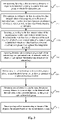
- Fig. 1 is a flow chart showing a method for optimizing thresholds based on K-edge imaging according to an embodiment of the present disclosure.
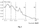
- Fig. 2 is a schematic diagram showing a preset threshold group in an embodiment of the present disclosure.
- the method for optimizing thresholds based on K-edge imaging may include the following steps.
- step S110 pre-scanning, by using a PCD, an object to be detected according to a preset threshold group, to obtain first detection data.
- a tube voltage of an X-ray machine may be set as 80 kV peak (kVp), 90 kVp, and 100 kVp, respectively, and the object to be detected may scanned using the PCD to obtain the first detection data.
- the abscissa is the preset threshold group (unit: electron volt keV), and the ordinate is a percentage of the number of photons to the total number of photons under this preset threshold group.
- the preset threshold group may set the scan as E1, E2, E3, E4 and E5 from low to high.
- the preset threshold group may also be other forms of combination, which is not limited herein.
- E1 25.3 keV
- E2 37.9 keV
- E3 50.5 keV
- E4 73.9 keV
- E5 100 keV.
- E2 and E4 may be selected using the energy equipartition method.
- E1, E3, and E5 may be fixed thresholds, while E2 and E4 may be thresholds to be optimized and may be divided into two groups, for example, E1 and E2, E3 and E4, and alternatively, may be divided into a plurality of groups, which is not limited herein.
- E1 and E2 may be inputted to the PCD to obtain a first set of detection data; and E3 and E4 may be inputted to the PCD to obtain a second set of detection data.
- the first and second set of detection data may constitute the first detection data.
- step S120 determining, according to the first detection data, line integral values of decomposition coefficients of individual basis functions in a basis function combination of each ray, wherein each ray has a fixed basis function combination.
- a pre-processing algorithm based on a maximum likelihood method may be generally used.
- the pre-processing algorithm may first decompose the first detection data, and then reconstruct the decomposed data using a reconstructing algorithm.
- h ( E', E ) is a response function of the PCD
- I is the number of photons after passing through the object to be detected
- I 0 is the initial number of photons before passing through the object to be detected
- the integral path L is a path of the X-ray passing through the object to be detected
- ⁇ ( r ,E ) is a liner attenuation coefficient of the object to be detected at the position r under
- the first detection data may be decomposed into a function related only to the path and a function related only to the energy.
- Equation (2) Defining an integral of the function related only to the path in the first detection data, as equation (2): ⁇ a ⁇ r ⁇ d r ⁇ ⁇ A ⁇ wherein, a ⁇ ( r ) is a distribution of the basis function in the object to be detected, A ⁇ is the line integral value, and ⁇ is the type of the basis function.
- the probability of the entire detecting process may be obtained.
- the maximum likelihood method may transform equation (6) to solve the following equation (7):
- a ⁇ 1 , ... , A ⁇ ⁇ arg min A ⁇ ⁇ A 1 ⁇ A ⁇
- the Newton iteration method may update equation (7) as the following equation (9):
- a 1 k + 1 ⁇ A ⁇ k + 1 A 1 k ⁇ A ⁇ k ⁇ ⁇ T 1 ⁇ A 1 ⁇ ⁇ T 1 ⁇ A ⁇ ⁇ ⁇ ⁇ T ⁇ ⁇ A 1 ⁇ ⁇ T ⁇ ⁇ A ⁇
- a ⁇ k is the number of iterations.
- step S130 selecting, according to the line integral values of the decomposition coefficients of the individual basis functions in the basis function combination of the each ray, rays of which a line integral value of a contrast agent material basis function in the fixed basis function combination is greater than a preset line integration threshold.
- the line integral value of the contrast agent material basis function that has been decomposed should be non-negative, but in practice, a negative value may occur due to the influence of noise.
- step S140 inputting detection data corresponding to each of the selected rays to a pre-trained neural network model, to obtain a local optimal threshold group of each of the selected rays.
- the detection data corresponding to the above described rays for which A T > ⁇ may be inputted to the pre-trained neural network model, to obtain the local optimal threshold group of the corresponding each ray.
- step S150 determining, based on local optimal threshold groups, a global optimal threshold group for K-edge imaging of the PCD.
- the method for optimizing thresholds it may be possible to roughly estimate an internal structure of the object to be detected using a low dose pre-scan form, thereby reducing the damage to the object to be detected.
- the global optimal threshold group may be obtained effectively for an unknown object to be detected.
- the use of the pre-trained neural network module to obtain the local optimal threshold group may improve the efficiency significantly.
- Fig. 3 is a detailed flowchart showing a method for optimizing thresholds according to another embodiment of the present disclosure, and the same or equivalent steps of Fig. 3 with Fig. 1 may use the same reference numerals.
- the method for optimizing thresholds in Fig. 3 may be substantially the same as the method for optimizing thresholds in Fig. 1 , except that the method for optimizing thresholds in Fig. 3 may further include the following steps.
- step S160 obtaining second detection data by using the PCD to scan the object to be detected with the thresholds to be optimized replaced by the global optimal threshold group.
- These five thresholds may be divided into two groups, for example, E1 and E2, E3 and E4, and alternatively, may be divided into a plurality of groups, which is not limited herein.
- the scanning steps in this embodiment may be the same as the pre-scanning steps in the above embodiments, and will not be described in detail herein. References may be made to the above embodiments.
- step S170 decomposing and/or reconstructing an image of the object to be detected based on the second detection data.
- the decomposition may be achieved utilizing the maximum likelihood method of equations (5)-(9) in the above embodiments, and the reconstruction of the distribution of the basis function solved above may be achieved using a common used reconstructing method such as the filtered back projection algorithm (FBP).
- FBP filtered back projection algorithm
- Fig. 4 is a schematic diagram showing a statistical local optimal threshold group in an embodiment of the present disclosure.
- the step S150 may include: counting a number of rays for each of the local optimal threshold groups, and using a local optimal threshold group corresponding to a largest number of rays as the global optimal threshold group.
- the ordinate is the number of rays
- the abscissa is the local optimal threshold group.
- Both E2 and E4 may be the thresholds to be optimized.
- the white bar may represent E2
- the black bar may represent E4
- the abscissa may indicate the appearance range of the local optimal threshold of E2 and E4
- the ordinate may indicate the number of rays present.
- the number of local optimal threshold groups of all rays may be counted to find the threshold group with the largest number.
- the pre-scanning may include: a sparse angle scan and/or a low dose scan.
- CT scans especially K-edge imaging
- more scans may cause more radiations.
- a low dose pre-scan may be performed on the object to be detected. Although this low dose pre-scan may cause errors in an estimation of the line integral values of the decomposition coefficients of the object to be detected, the influence of the errors on the subsequent threshold optimization may be relatively small. Therefore, the low dose pre-scan may be an acceptable way to obtain the internal structure of the object to be detected.
- a sparse angle scan, or a combination of the low dose scan and the sparse angle scan and the like may also be used.
- the basis function combination may include: a photoelectric coefficient basis function and a Compton coefficient basis function.
- the result of the decomposition may also be different.
- the threshold optimization for K-edge imaging thus it may be necessary to select one basis function as the linear attenuation coefficient of the contrast agent material.
- the basis function combination may be fixed as the photoelectric coefficient, the Compton coefficient, and the linear attenuation coefficient of the contrast agent material. In this manner, when calculating a noise lower bound, only the noise lower bound of the linear attenuation coefficient of the contrast agent material may be calculated and optimized. Therefore, it may be possible to avoid the influence of the difference of the decomposition basis function selection, and thus only focus on the threshold optimization for K-edge imaging.
- Fig. 5 is a structural schematic diagram showing a training motif used in an embodiment of the present disclosure.
- the pre-trained neural network model may be a model obtained by using the local optimal threshold group as an output of a neural network model, and using the detection data corresponding to each of the selected rays as an input of the neural network model.
- the local optimal threshold group may comprise thresholds for the K-edge imaging of the PCD determined by the enumeration method when the noise lower bound of the contrast agent material basis function is minimum, wherein the noise lower bound of the contrast agent material may be determined by the Cramer-Rao lower bound theory.
- the local optimal threshold group may be used as the input of the neural network model.
- the thresholds for the K-edge imaging of the PCD when the noise lower bound of the contrast agent material basis function is minimum may be determined by the enumeration method, while the noise lower bound of the contrast agent material basis function may be determined by the Cramer-Rao lower bound (CRLB) theory.
- the tube voltage of the X-ray machine may be set as 80 kVp, 90 kVp, 100 kVp, respectively, and the training motif as shown in Fig. 5 may be scanned using the PCD to get a training data.
- the training motif may include: water, 0.5% Gd. 0.4% Gd, 1% Gd, 1.5% Gd, air, 10% CaCl 2 , and polymethyl methacrylate PMMA.
- the optimal thresholds may be determined by setting different thresholds.
- the noise lower bound of ( ⁇ 1 ,..., ⁇ ⁇ ) may be calculated by the CRLB theory.
- each element in the Fisher information matrix may be obtained by solving equation (16), so as to enumerate the noise lower bounds of this ray under all threshold combinations.
- the minimum noise lower bound and the threshold group corresponding to the minimum noise lower bound may be found, and this threshold group may be the local optimal threshold group on this ray.
- the time required for the calculation may be very long.
- the enumerate method may need to be accelerated.
- the look-up table method may be commonly used, in which the local optimal threshold group of each ray may be outputted by inputting the detection data of the ray.
- the physical quantities associated with the local optimal threshold group may include: an energy spectrum I 0 ( E ) of the ray machine, a line integral value A ⁇ of the various basis function, the basis function ⁇ ⁇ ( E ), and H( i ,E), wherein all the I 0 ( E ), ⁇ ⁇ ( E ), and H( i ,E) are vectors.
- a neural network model may therefore be used to obtain the local optimal threshold group of the individual ray.
- the efficiency for obtaining the local optimal threshold group of the individual ray may be increased greatly.
- the inputs of the neural network model should contain all relevant factors on the ray; and the output should be the local optimal threshold group of this ray.
- the factors effecting the CRLB noise lower bound of a certain ray may include: the energy spectrum I 0 ( E ) of the ray machine, the various basis function ⁇ ⁇ (E), the line integral value A ⁇ , H( i ,E), and the various thresholds E. Due to the need to obtain the local optimal threshold group of a certain ray, all the other influence factors except the threshold E should be used as the input end of the neural network model.
- the threshold E may exist only in the upper and lower limits of the integral of each item, while the input end of the neural network model may not be effected by the threshold E.
- the input end of the neural network model may be set as the portion inside the integral sign of each item in equation (16).
- hÎ ⁇ i' j is a response function matrix of the calibrated PCD
- i is the number of thresholds recovered by the response function
- j is number of thresholds obtained by sweeping the spectrum in actual experiments, and i and j may not need to be completely consistent in actual use.
- I 0 Î ⁇ j' 1 is the original energy spectrum of the ray machine, i.e., a discrete representation of the I 0 ( E ) in equation (16); ⁇ ⁇ Î ⁇ j ' 1 is an attenuation coefficient of the ⁇ -th basis function, i.e., a discrete representation of the ⁇ ⁇ ( E ) in equation (17); and f Î ⁇ j ' 1 is a discrete representation of the ⁇ ( E ) defined by equation (17).
- ⁇ represents a matrix multiplication
- e represents an element multiplication from bit to bits
- D 0 , D 1 , D 2 , D 3 may be vectors of the same dimension
- the four vectors D 0 , D 1 , D 2 , D 3 may be arranged into a new vector in the order of D 0 , D 1 , D 2 , D 3 .
- the new vector may be used as the input of the neural network model, and the thresholds of the K-edge imaging of the PCD determined by the enumeration method when the noise lower bound of the contrast agent material basis function is minimum may be used as the output of the neural network model.
- the error inverse propagation algorithm may be utilized to train the neuron parameters of the neural network model, to obtain a trained neural network model, i.e., the pre-trained neural network model.
- Fig. 6 is a structural schematic diagram showing the pre-trained neural network model in an embodiment of the present disclosure.
- the input layer, output layer and hidden layer of the model may need be designed according to the actual problem.
- the neural network model may use the BP fully connected neural network model.
- the design of the input layer, output layer and hidden layer of the model may be the design of the number of neurons and the type of response functions of the model.
- a large number of layers may increase the training difficulty of the BP fully connected neural network model and slow down the training.
- the structure of the BP fully connected neural network model is too complicated, this may cause an over-fitting for the BP fully connected neural network model. That is, the fitting degree of the training set may be too strict, resulting in that the BP fully connected neural network model may be difficult to apply to other situations than the training set, and decreasing the generalization performance of the BP fully connected neural network model.
- a BP fully connected neural network model with a single hidden layer may be usually utilized.
- a BP fully connected neural network model with more than one hidden layer may be required.
- there is not an acknowledged method for selecting the number of layers of the network but it is default that a network with a single hidden layer may be utilized for continuous problems, and a network with a plurality of hidden layer may be utilized for discontinuous problems.
- the neurons in hidden layers may significantly affect the result of the BP fully connected neural network model.
- the BP fully connected neural network model may learn relevant rules from sample data, if the number of nodes is too small, the learning degree of the BP fully connected neural network model for the training data may be insufficient, which may cause the data feature of the training data could not be obtained well. And if the number of nodes is too large, it may also cause an over-fitting of the BP fully connected neural network model. Thus, in the design of the BP fully connected neural network model, it may be necessary to select an appropriate number of neurons to make various performances of the BP fully connected neural network model to be better.
- the trial and error method may be generally used.
- the neural network model may need to utilize a multi-hidden layer structure.
- a two hidden layer structure may be utilized.
- the pre-trained neural network model may include: an input layer, a hidden layer 1, a hidden layer 2, and an output layer.
- the number of neurons in each hidden layer may be estimated firstly by equation (19), and then adjusted around the estimated value.
- the utilized neural network model may be a BP neural network model with two hidden layers, wherein the number of neurons in the hidden layer 1 may be 25, and the number of neurons in the hidden layer 2 may be 40.
- Fig. 7 is a structural schematic diagram showing a testing motif used in an embodiment of the present disclosure.
- the energy step interval of the response function of the PCD is 1.8 KeV
- one unit length may be defines as 1.8 KeV.
- the testing motif as shown in Fig. 7 may be used, which may include: water, 2% Gd, 1.75% Gd, 1.25% Gd, 0.75% Gd, air, 4% CaCl 2 and polymethyl methacrylate PMMA.
- the tube voltage of the X-ray machine may be set as 95 kVp.
- the threshold settings of the pre-scanning may be the same as that of step S110, to obtain the testing data of the pre-scanning under each threshold, and calculate line integral values of individual basis functions of each ray.
- the testing data of the selected ray may be input to the trained neural network model to obtain the local optimal threshold of each ray output by the network.
- Fig. 8 is a structural schematic diagram showing an apparatus for optimizing thresholds based on K-edge imaging provided by an embodiment of the present disclosure.
- the apparatus 800 for optimizing thresholds may include: a line integral value determining module 810, a selecting module 820, a pre-trained neural network model module 830, and an integrating module840.
- the line integral value determining module 810 may be configured to determine, according to a first detection data, line integral values of decomposition coefficients of individual basis functions in a basis function combination of each ray, wherein each ray may have a fixed basis function combination; and wherein, the first detection data may be obtained by using a PCD to pre-scan an object to be detected according to a preset threshold group.
- the selecting module 820 may be configured to select, according to the line integral values of the decomposition coefficients of the individual basis functions in the basis function combination of the each ray, rays of which a line integral value of a contrast agent material basis function in the fixed basis function combination is greater than a preset line integration threshold.
- the pre-trained neural network model module 830 may be configured to input detection data corresponding to each of the selected rays to a pre-trained neural network model, to obtain a local optimal threshold group of each of the selected rays.
- the integrating module 840 may be configured to determine, based on local optimal threshold groups, a global optimal threshold group for K-edge imaging of the PCD.
- the apparatus for optimizing thresholds it may be possible to roughly estimate the internal structure of the object to be detected using a low dose pre-scan form, thereby reducing the damage to the object to be detected.
- the global optimal threshold group may be obtained effectively for an unknown object to be detected.
- the use of the pre-trained neural network module to obtain the local optimal threshold group may improve the efficiency significantly.
- the preset threshold group may include fixed thresholds and thresholds to be optimized, and the thresholds to be optimized may be obtained by an energy equipartition manner.
- Fig. 9 is a structural schematic diagram showing an apparatus for optimizing thresholds according to another embodiment of the present disclosure, and the same or equivalent modules of Fig. 9 with Fig. 8 may use the same reference numerals.
- the apparatus 900 for optimizing thresholds may be substantially the same as the apparatus 800 for optimizing thresholds, except that the apparatus 900 for optimizing thresholds may further include: a decomposing and/or reconstructing module 850 which may be configured to decompose and/or reconstruct an image of the object to be detected based on second detection data, wherein the second detection data may be obtained by using the PCD to scan the object to be detected with the thresholds to be optimized replaced by the global optimal threshold group.
- a decomposing and/or reconstructing module 850 which may be configured to decompose and/or reconstruct an image of the object to be detected based on second detection data, wherein the second detection data may be obtained by using the PCD to scan the object to be detected with the thresholds to be optimized replaced by the global optimal threshold group.
- the integrating module 840 may be configured to count a number of rays for each of the local optimal threshold groups, and use a local optimal threshold group corresponding to a largest number as the global optimal threshold group.
- the pre-scanning may include: a sparse angle scan and/or a low dose scan.
- the line integral value determining module 810 may be configured to calculate the first detection data using a maximum likelihood decomposition method, to determine the line integral values of the decomposition coefficients of individual basis functions in the basis function combination of each ray.
- the basis function combination may include: a photoelectric coefficient basis function and a Compton coefficient basis function.
- the pre-trained neural network model may be obtained a model by using the local optimal threshold group as an output of a neural network model, and using the detection data corresponding to each of the selected rays as an input of the neural network model.
- the local optimal threshold group may comprise thresholds for the K-edge imaging of the PCD determined by an enumeration method when a noise lower bound of the contrast agent material basis function is minimum, wherein the noise lower bound of the contrast agent material basis function may be determined by the CRLB theory.
- Fig. 10 is a block diagram showing an exemplary hardware architecture of a computing device capable of implementing the method and apparatus for optimizing thresholds in accordance with embodiments of the present disclosure.
- the computing device 1000 may include: an input device 1001, an input interface 1002, a central processor 1003, a memory 1004, an output interface 1005, and an output device 1006.
- the input interface 1002, the central processor 1003, the memory 1004, the output interface 1005 may connect with each other by a bus 1010
- the input device 1001 and the output device 1006 may connect with the bus 1010 through the input interface 1002 and the output interface 1005, respectively, and further with other components of the computing device 1000.
- the input device 1001 may receive input information from the outside, and transmit the input information to the central processor 1003 through the input interface 1002; the central processor 1003 may process the input formation based on computer executable instructions stored in the memory 1004 to generate output information, and store the output information in the memory 1004 temporarily or permanently, and then transmit the output information to the output device 1006 through the output interface 1005; and the output device 1006 may output the output information to the outside of the computing device 1000 for use by the user.
- the computing device 1000 as shown in Fig. 10 may be implemented as a terminal device, which may include: a memory and a processor; the memory may be configured to store executable program codes; and the processor may be configured to read the executable program codes stored in the memory to perform the method for optimizing thresholds of the above embodiments.
- the above described embodiments may be implemented in whole or in part by software, hardware, firmware, or any combination thereof.
- the above described embodiments may be implemented in whole or in part in the form of computer program product or computer readable storage medium.
- the computer program product or computer readable storage medium may include one or more computer instructions.
- the computer program instructions when loaded an executed by a computer, may product in whole or in part the processes or functions described in accordance with embodiments of the present disclosure.
- the computer may be a general purpose computer, a special purpose computer, a computer network, or other programmable devices.
- the computer instructions may be stored in a computer readable storage medium, or transferred from one computer readable storage medium to another one, for example, the computer instructions may be transmitted from a website site, a computer, a server or data center to another website site, computer, server or data center by wire (e.g., coaxial cable, fiber optic, digital subscriber line (DSL)) or wireless (e.g., infrared, wireless, microwave, etc.) means.
- the computer readable storage medium may be any available medium accessible to a computer, or a data storage device, such as a server, a date center, containing one or more available medium integration.
- the available medium may be a magnetic medium (e.g., a floppy disk, a hard disk, a magnetic tape), an optical medium (e.g., DVD), or a semiconductor (e.g., a Solid State Disk (SSD)), and the like.
- a magnetic medium e.g., a floppy disk, a hard disk, a magnetic tape
- an optical medium e.g., DVD
- a semiconductor e.g., a Solid State Disk (SSD)
Landscapes
- Health & Medical Sciences (AREA)
- Life Sciences & Earth Sciences (AREA)
- Engineering & Computer Science (AREA)
- Medical Informatics (AREA)
- Physics & Mathematics (AREA)
- General Health & Medical Sciences (AREA)
- Pathology (AREA)
- Nuclear Medicine, Radiotherapy & Molecular Imaging (AREA)
- Biomedical Technology (AREA)
- Radiology & Medical Imaging (AREA)
- Biophysics (AREA)
- Molecular Biology (AREA)
- Animal Behavior & Ethology (AREA)
- Surgery (AREA)
- Public Health (AREA)
- High Energy & Nuclear Physics (AREA)
- Optics & Photonics (AREA)
- Veterinary Medicine (AREA)
- Heart & Thoracic Surgery (AREA)
- Theoretical Computer Science (AREA)
- General Physics & Mathematics (AREA)
- Analytical Chemistry (AREA)
- Immunology (AREA)
- Biochemistry (AREA)
- Chemical & Material Sciences (AREA)
- Pulmonology (AREA)
- Multimedia (AREA)
- Signal Processing (AREA)
- Artificial Intelligence (AREA)
- Computational Linguistics (AREA)
- Data Mining & Analysis (AREA)
- Evolutionary Computation (AREA)
- Computing Systems (AREA)
- General Engineering & Computer Science (AREA)
- Mathematical Physics (AREA)
- Software Systems (AREA)
- Apparatus For Radiation Diagnosis (AREA)
Claims (15)
- Procédé d'optimisation de seuils basé sur l'imagerie K-edge, comprenant :pré-balayer (S110), par un détecteur de comptage photonique, un objet à détecter selon un groupe de seuils prédéfinis, de sorte d'obtenir des premières données de détection ;déterminer (S120), en fonction des premières données de détection, des valeurs d'intégration linaire de coefficients de décomposition de fonctions de base individuelles dans une combinaison de fonctions de base de chaque rayon, dans lequel chaque rayon correspond à une combinaison de fonctions de base fixe ;sélectionner (S130), en fonction des valeurs d'intégration linaire des coefficients de décomposition des fonctions de base individuelles dans la combinaison de fonctions de base de chaque rayon, des rayons dont une valeur d'intégration linaire de la fonction de base d'un matériau d'agent de contraste dans la combinaison de fonctions de base fixe est supérieure à un seuil d'intégration linaire prédéfini ;entrer (S 140) des données de détection correspondant à chacun des rayons sélectionnés dans un modèle de réseau de neurones pré-entraîné, de sorte d'obtenir un groupe de seuils optimal local de chacun des rayons sélectionnés ; etdéterminer (S150), sur la base des groupes de seuils optimaux locaux, un groupe de seuils optimal global pour une imagerie K-edge du détecteur de comptage photonique.
- Procédé selon la revendication 1, dans lequel le groupe de seuils prédéfinis comprend des seuils fixes et des seuils à optimiser, les seuils à optimiser étant obtenus par une méthode d'équipartition énergétique.
- Procédé selon la revendication 2, comprenant en outre, après l'étape de déterminer (S150), sur la base des groupes de seuils optimaux locaux, le groupe de seuils optimal global pour l'imagerie K-edge du détecteur de comptage photonique :acquérir (S 160), par le détecteur de comptage photonique, des deuxièmes données de détection, pour balayer l'objet à détecter avec les seuils à optimiser remplacés par le groupe de seuil optimal global ; etdécomposer et/ou reconstruire (S170) une image de l'objet à détecter sur la base des deuxièmes données de détection.
- Procédé selon la revendication 1, dans lequel, l'étape de déterminer (S150), sur la base des groupes de seuils optimaux locaux, le groupe de seuils optimal global pour l'imagerie K-edge du détecteur de comptage photonique comprend :
compter un nombre de rayons pour chacun des groupes de seuils optimaux locaux, et utiliser un groupe de seuils optimal local correspondant au plus grand nombre de rayons comme groupe de seuils optimal global. - Procédé selon la revendication 1, dans lequel l'étape de déterminer (S120), en fonction des premières données de détection, les valeurs d'intégration linaire des coefficients de décomposition des fonctions de base individuelles dans la combinaison de fonctions de base de chaque rayon comprend :
calculer les premières données de détection par une méthode de décomposition de vraisemblance maximale, de sorte de déterminer les valeurs d'intégration linaire des coefficients de décomposition des fonctions de base individuelles dans la combinaison de fonctions de base de chaque rayon. - Procédé selon la revendication 1, dans lequel la combinaison de fonctions de base comprend : une fonction de base de coefficient photoélectrique et une fonction de base de coefficient Compton.
- Procédé selon la revendication 1, dans lequel le modèle de réseau de neurones pré-entraîné est un modèle obtenu en utilisant le groupe de seuils optimal local comme sortie d'un modèle de réseau de neurones et en utilisant les données de détection correspondant à chacun des rayons sélectionnés comme entrée du modèle de réseau de neurones,
dans lequel le groupe de seuils optimal local comprend des seuils pour l'imagerie K-edge du détecteur de comptage photonique déterminés par une méthode d'énumération lorsqu'une limite inférieure de bruit de la fonction de base du matériau d'agent de contraste est minimale, la limite inférieure de bruit de la fonction de base du matériau d'agent de contraste étant déterminée sur la base d'une théorie de limite inférieure Cramer-Rao. - Appareil (800, 900) d'optimisation de seuils basé sur l'imagerie K-edge, comprenant :un module de détermination de valeur d'intégration linaire (810), un module de sélection (820), un module de modèle de réseau de neurones pré-entraîné (830) et un module d'intégration (840) ;le module de détermination de valeur d'intégration linaire (810) étant configuré pour déterminer, en fonction des premières données de détection, des valeurs d'intégration linaire de coefficients de décomposition de fonctions de base individuelles dans une combinaison de fonctions de base de chaque rayon, dans lequel chaque rayon correspond à une combinaison de fonctions de base fixe ; et les premières données de détection sont obtenues en pré-balayant, par le détecteur de comptage photonique, un objet à détecter selon un groupe de seuils prédéfinis ;le module de sélection (820) étant configuré pour sélectionner, en fonction des valeurs d'intégration linaire des coefficients de décomposition des fonctions de base individuelles dans la combinaison de fonctions de base de chaque rayon, des rayons dont une valeur d'intégration linaire de la fonction de base d'un matériau d'agent de contraste dans la combinaison de fonctions de base fixe est supérieure à un seuil d'intégration linaire prédéfini ;le module de modèle de réseau de neurones pré-entraîné (830) étant configuré pour entrer des données de détection correspondant à chacun des rayons sélectionnés dans un modèle de réseau de neurones pré-entraîné, de sorte d'obtenir un groupe de seuils optimal local de chacun des rayons sélectionnés ; etle module d'intégration (840) étant configuré pour déterminer, sur la base des groupes de seuils optimaux locaux, un groupe de seuils optimal global pour l'imagerie K-edge du détecteur de comptage photonique.
- Appareil (800, 900) selon la revendication 8, dans lequel le groupe de seuils prédéfinis comprend des seuils fixes et des seuils à optimiser, les seuils à optimiser étant obtenus par une méthode d'équipartition énergétique.
- Appareil (800, 900) selon la revendication 9, comprenant en outre :un module de décomposition et/ou reconstruction (850),le module de décomposition et/ou reconstruction (850) étant configuré pour décomposer et/ou reconstruire une image de l'objet à détecter sur la base des deuxièmes données de détection, dans lequel les deuxièmes données de détection sont obtenues en balayant, par le détecteur de comptage photonique, l'objet à détecter avec les seuils à optimiser remplacés par le groupe de seuil optimal global.
- Appareil (800, 900) selon la revendication 8, dans lequel le module d'intégration (840) est configuré en outre pour :
compter un nombre de rayons pour chacun des groupes de seuils optimaux locaux, et utiliser un groupe de seuils optimal local correspondant au plus grand nombre de rayons comme groupe de seuils optimal global. - Appareil (800, 900) selon la revendication 8, dans lequel le module de détermination de valeur d'intégration linaire (810) est configuré en outre pour :
calculer les premières données de détection par une méthode de décomposition de vraisemblance maximale, de sorte de déterminer les valeurs d'intégration linaire des coefficients de décomposition des fonctions de base individuelles dans la combinaison de fonctions de base de chaque rayon. - Appareil (800, 900) selon la revendication 8, dans lequel la combinaison de fonctions de base comprend : une fonction de base de coefficient photoélectrique et une fonction de base de coefficient Compton.
- Appareil (800, 900) selon la revendication 8, dans lequel le modèle de réseau de neurones pré-entraîné est un modèle obtenu en utilisant le groupe de seuils optimal local comme sortie d'un modèle de réseau de neurones et en utilisant les données de détection correspondant à chacun des rayons sélectionnés comme entrée du modèle de réseau de neurones, dans lequel le groupe de seuils optimal local comprend des seuils pour l'imagerie K-edge du détecteur de comptage photonique déterminés par une méthode d'énumération lorsqu'une limite inférieure de bruit de la fonction de base du matériau d'agent de contraste est minimale, la limite inférieure de bruit de la fonction de base du matériau d'agent de contraste étant déterminée sur la base d'une théorie de limite inférieure Cramer-Rao.
- Support de stockage de comptage comprenant des instructions qui, lorsqu'elles sont exécutées sur un ordinateur, amènent l'ordinateur à exécuter le procédé d'optimisation de seuils selon l'une quelconque des revendications 1 à 7.
Applications Claiming Priority (2)
| Application Number | Priority Date | Filing Date | Title |
|---|---|---|---|
| CN201810942770.6A CN110836901B (zh) | 2018-08-17 | 2018-08-17 | 基于k边缘成像的优化阈值方法、装置、设备和介质 |
| PCT/CN2019/087220 WO2020034679A1 (fr) | 2018-08-17 | 2019-05-16 | Procédé d'optimisation de valeur seuil et appareil basé sur l'imagerie de bord k, dispositif, et milieu |
Publications (3)
| Publication Number | Publication Date |
|---|---|
| EP3632328A1 EP3632328A1 (fr) | 2020-04-08 |
| EP3632328A4 EP3632328A4 (fr) | 2021-08-18 |
| EP3632328B1 true EP3632328B1 (fr) | 2022-04-06 |
Family
ID=69525060
Family Applications (1)
| Application Number | Title | Priority Date | Filing Date |
|---|---|---|---|
| EP19762285.5A Not-in-force EP3632328B1 (fr) | 2018-08-17 | 2019-05-16 | Procédé d'optimisation de valeur seuil et appareil basé sur l'imagerie de bord k, dispositif, et milieu |
Country Status (3)
| Country | Link |
|---|---|
| EP (1) | EP3632328B1 (fr) |
| CN (1) | CN110836901B (fr) |
| WO (1) | WO2020034679A1 (fr) |
Families Citing this family (3)
| Publication number | Priority date | Publication date | Assignee | Title |
|---|---|---|---|---|
| CN111413357B (zh) * | 2020-04-20 | 2022-01-07 | 中国科学院高能物理研究所 | X射线吸收边探测信号增强方法、装置、设备及存储介质 |
| CN113711080B (zh) * | 2020-12-31 | 2023-08-04 | 深圳市速腾聚创科技有限公司 | 激光雷达的探测方法、计算机可读存储介质和激光雷达 |
| CN115424321B (zh) * | 2022-08-19 | 2026-01-27 | 奥比中光科技集团股份有限公司 | 模型输入数据的预处理方法、装置及图像识别设备 |
Family Cites Families (18)
| Publication number | Priority date | Publication date | Assignee | Title |
|---|---|---|---|---|
| US6408050B1 (en) * | 2000-09-14 | 2002-06-18 | Ge Medical Systems Global Technology Company, Llc | X-ray detector and method for tissue specific image |
| US7769138B2 (en) * | 2004-03-29 | 2010-08-03 | Cmt Medical Technologies Ltd. | Apparatus and method of improved angiographic imaging |
| CN101410871A (zh) * | 2006-03-29 | 2009-04-15 | 皇家飞利浦电子股份有限公司 | 双能x射线成像中的噪声降低 |
| CN102076263B (zh) * | 2008-06-30 | 2013-06-19 | 皇家飞利浦电子股份有限公司 | 频谱ct |
| CN102088907B (zh) * | 2008-07-07 | 2013-03-27 | 皇家飞利浦电子股份有限公司 | K边缘成像 |
| US8378310B2 (en) * | 2009-02-11 | 2013-02-19 | Prismatic Sensors Ab | Image quality in photon counting-mode detector systems |
| US8422636B2 (en) * | 2010-10-12 | 2013-04-16 | Ge Medical Systems Israel, Ltd. | Photon counting and energy discriminating detector threshold calibration |
| CN103200873B (zh) * | 2011-08-18 | 2015-05-20 | 株式会社东芝 | 光子计数型的x射线计算机断层装置以及散射线校正方法 |
| JP6238584B2 (ja) * | 2012-07-17 | 2017-11-29 | 東芝メディカルシステムズ株式会社 | X線ct装置およびx線ct装置の制御方法 |
| DE102012217301B4 (de) * | 2012-09-25 | 2021-10-14 | Bayer Pharma Aktiengesellschaft | Kombination aus Kontrastmittel und Mammographie-CT-System mit vorgegebenem Energiebereich und Verfahren zur Erzeugung tomographischer Mammographie-CT-Aufnahmen durch diese Kombination |
| CN102920434B (zh) * | 2012-10-23 | 2014-11-26 | 天津大学 | 荧光―光学联合断层成像系统及测量方法 |
| CN103913472B (zh) * | 2012-12-31 | 2016-04-20 | 同方威视技术股份有限公司 | Ct成像系统和方法 |
| CN104422704B (zh) * | 2013-08-21 | 2017-07-25 | 同方威视技术股份有限公司 | 对x光能谱ct的能谱信息进行分解的方法和对应的重建方法 |
| WO2015052000A1 (fr) * | 2013-10-09 | 2015-04-16 | Koninklijke Philips N.V. | Procédé et dispositif permettant de générer une image radiologique résolue en énergie avec un seuil énergétique adapté |
| JP6747787B2 (ja) * | 2014-08-22 | 2020-08-26 | キヤノンメディカルシステムズ株式会社 | 光子計数型x線ct装置 |
| US10165996B2 (en) * | 2015-09-30 | 2019-01-01 | General Electric Company | Systems and methods for dual-energy computed tomography imaging |
| DE102016217984A1 (de) * | 2016-09-20 | 2018-04-05 | Siemens Healthcare Gmbh | Sinogrammbasierte Streustrahlenkorrektur in der Computertomographie |
| CN107677692A (zh) * | 2017-09-21 | 2018-02-09 | 中国科学院上海应用物理研究所 | 一种防腐剂处理的竹材或木材的无损检测方法 |
-
2018
- 2018-08-17 CN CN201810942770.6A patent/CN110836901B/zh active Active
-
2019
- 2019-05-16 WO PCT/CN2019/087220 patent/WO2020034679A1/fr not_active Ceased
- 2019-05-16 EP EP19762285.5A patent/EP3632328B1/fr not_active Not-in-force
Also Published As
| Publication number | Publication date |
|---|---|
| CN110836901A (zh) | 2020-02-25 |
| EP3632328A1 (fr) | 2020-04-08 |
| CN110836901B (zh) | 2020-09-04 |
| EP3632328A4 (fr) | 2021-08-18 |
| WO2020034679A1 (fr) | 2020-02-20 |
Similar Documents
| Publication | Publication Date | Title |
|---|---|---|
| US20230206517A1 (en) | Systems and methods for image reconstruction in positron emission tomography | |
| Ding et al. | Image‐domain multimaterial decomposition for dual‐energy CT based on prior information of material images | |
| US20170311918A1 (en) | Apparatus and method for hybrid pre-log and post-log iterative image reconstruction for computed tomography | |
| JP6386997B2 (ja) | X線コンピュータ断層撮影装置及び補正方法 | |
| US11568582B2 (en) | System and method for reconstructing an image | |
| US9700264B2 (en) | Joint estimation of tissue types and linear attenuation coefficients for computed tomography | |
| Gaitanis et al. | PET image reconstruction: A stopping rule for the MLEM algorithm based on properties of the updating coefficients | |
| Li et al. | X-ray photon-counting data correction through deep learning | |
| US20180336709A1 (en) | Method and devices for image reconstruction | |
| EP3632328A1 (fr) | Procédé d'optimisation de valeur seuil et appareil basé sur l'imagerie de bord k, dispositif, et milieu | |
| Nakada et al. | Joint estimation of tissue types and linear attenuation coefficients for photon counting CT | |
| Elhamiasl et al. | Low-dose x-ray CT simulation from an available higher-dose scan | |
| US20240202885A1 (en) | Methods and systems for image processing | |
| EP4322856B1 (fr) | Système pour générer des images mono-énergétiques virtuelles à faible énergie à partir de données de tomodensitométrie multi-énergie | |
| CN117274080B (zh) | 一种低剂量ct弦图恢复方法及相关装置 | |
| CN115049554A (zh) | 基于Swin Transformer的低剂量CT去噪方法 | |
| Yang et al. | Empirical optimization of energy bin weights for compressing measurements with realistic photon counting x‐ray detectors | |
| US12254539B2 (en) | Systems and methods of guided PET reconstruction with adaptive prior strength | |
| WO2024138726A1 (fr) | Système et procédé d'imagerie médicale | |
| US12406410B2 (en) | System and method for reconstructing an image | |
| Wang et al. | Nonconvex weighted variational metal artifacts removal via convergent primal-dual algorithms | |
| Jin et al. | Virtual and real-world implementation of deep-learning-based image denoising model on projection domain in digital tomosynthesis and cone-beam computed tomography data | |
| Ma et al. | Deep plug-and-play denoising prior with total variation regularization for low-dose CT | |
| Yao et al. | Iterative dynamic dual-energy CT algorithm in reducing statistical noise in multi-energy CT imaging | |
| Ramyar et al. | Establishing a method to measure bone structure using spectral CT |
Legal Events
| Date | Code | Title | Description |
|---|---|---|---|
| STAA | Information on the status of an ep patent application or granted ep patent |
Free format text: STATUS: UNKNOWN |
|
| STAA | Information on the status of an ep patent application or granted ep patent |
Free format text: STATUS: THE INTERNATIONAL PUBLICATION HAS BEEN MADE |
|
| PUAI | Public reference made under article 153(3) epc to a published international application that has entered the european phase |
Free format text: ORIGINAL CODE: 0009012 |
|
| STAA | Information on the status of an ep patent application or granted ep patent |
Free format text: STATUS: REQUEST FOR EXAMINATION WAS MADE |
|
| 17P | Request for examination filed |
Effective date: 20190911 |
|
| AK | Designated contracting states |
Kind code of ref document: A1 Designated state(s): AL AT BE BG CH CY CZ DE DK EE ES FI FR GB GR HR HU IE IS IT LI LT LU LV MC MK MT NL NO PL PT RO RS SE SI SK SM TR |
|
| AX | Request for extension of the european patent |
Extension state: BA ME |
|
| RIN1 | Information on inventor provided before grant (corrected) |
Inventor name: XING, YUXIANG Inventor name: CHEN, ZHIQIANG Inventor name: LIU, YINONG Inventor name: HUANG, KAIXIN Inventor name: SHEN, LE Inventor name: DENG, ZHI Inventor name: ZHANG, LI |
|
| A4 | Supplementary search report drawn up and despatched |
Effective date: 20210721 |
|
| RIC1 | Information provided on ipc code assigned before grant |
Ipc: A61B 6/03 20060101AFI20210715BHEP Ipc: G01T 1/24 20060101ALI20210715BHEP Ipc: A61B 6/00 20060101ALI20210715BHEP Ipc: G06N 3/00 20060101ALI20210715BHEP Ipc: G06N 20/00 20190101ALI20210715BHEP Ipc: H04N 5/32 20060101ALI20210715BHEP Ipc: H05G 1/00 20060101ALI20210715BHEP Ipc: H05H 9/00 20060101ALI20210715BHEP |
|
| DAV | Request for validation of the european patent (deleted) | ||
| DAX | Request for extension of the european patent (deleted) | ||
| GRAP | Despatch of communication of intention to grant a patent |
Free format text: ORIGINAL CODE: EPIDOSNIGR1 |
|
| STAA | Information on the status of an ep patent application or granted ep patent |
Free format text: STATUS: GRANT OF PATENT IS INTENDED |
|
| RIC1 | Information provided on ipc code assigned before grant |
Ipc: G06N 3/08 20060101ALI20211027BHEP Ipc: H05H 9/00 20060101ALI20211027BHEP Ipc: H05G 1/00 20060101ALI20211027BHEP Ipc: H04N 5/32 20060101ALI20211027BHEP Ipc: G06N 20/00 20190101ALI20211027BHEP Ipc: G06N 3/00 20060101ALI20211027BHEP Ipc: A61B 6/00 20060101ALI20211027BHEP Ipc: G01T 1/24 20060101ALI20211027BHEP Ipc: A61B 6/03 20060101AFI20211027BHEP |
|
| INTG | Intention to grant announced |
Effective date: 20211125 |
|
| GRAS | Grant fee paid |
Free format text: ORIGINAL CODE: EPIDOSNIGR3 |
|
| GRAA | (expected) grant |
Free format text: ORIGINAL CODE: 0009210 |
|
| STAA | Information on the status of an ep patent application or granted ep patent |
Free format text: STATUS: THE PATENT HAS BEEN GRANTED |
|
| AK | Designated contracting states |
Kind code of ref document: B1 Designated state(s): AL AT BE BG CH CY CZ DE DK EE ES FI FR GB GR HR HU IE IS IT LI LT LU LV MC MK MT NL NO PL PT RO RS SE SI SK SM TR |
|
| REG | Reference to a national code |
Ref country code: GB Ref legal event code: FG4D |
|
| REG | Reference to a national code |
Ref country code: CH Ref legal event code: EP |
|
| REG | Reference to a national code |
Ref country code: AT Ref legal event code: REF Ref document number: 1480548 Country of ref document: AT Kind code of ref document: T Effective date: 20220415 |
|
| REG | Reference to a national code |
Ref country code: IE Ref legal event code: FG4D |
|
| REG | Reference to a national code |
Ref country code: DE Ref legal event code: R096 Ref document number: 602019013521 Country of ref document: DE |
|
| REG | Reference to a national code |
Ref country code: LT Ref legal event code: MG9D |
|
| REG | Reference to a national code |
Ref country code: NL Ref legal event code: MP Effective date: 20220406 |
|
| REG | Reference to a national code |
Ref country code: AT Ref legal event code: MK05 Ref document number: 1480548 Country of ref document: AT Kind code of ref document: T Effective date: 20220406 |
|
| PG25 | Lapsed in a contracting state [announced via postgrant information from national office to epo] |
Ref country code: NL Free format text: LAPSE BECAUSE OF FAILURE TO SUBMIT A TRANSLATION OF THE DESCRIPTION OR TO PAY THE FEE WITHIN THE PRESCRIBED TIME-LIMIT Effective date: 20220406 |
|
| PG25 | Lapsed in a contracting state [announced via postgrant information from national office to epo] |
Ref country code: SE Free format text: LAPSE BECAUSE OF FAILURE TO SUBMIT A TRANSLATION OF THE DESCRIPTION OR TO PAY THE FEE WITHIN THE PRESCRIBED TIME-LIMIT Effective date: 20220406 Ref country code: PT Free format text: LAPSE BECAUSE OF FAILURE TO SUBMIT A TRANSLATION OF THE DESCRIPTION OR TO PAY THE FEE WITHIN THE PRESCRIBED TIME-LIMIT Effective date: 20220808 Ref country code: NO Free format text: LAPSE BECAUSE OF FAILURE TO SUBMIT A TRANSLATION OF THE DESCRIPTION OR TO PAY THE FEE WITHIN THE PRESCRIBED TIME-LIMIT Effective date: 20220706 Ref country code: LT Free format text: LAPSE BECAUSE OF FAILURE TO SUBMIT A TRANSLATION OF THE DESCRIPTION OR TO PAY THE FEE WITHIN THE PRESCRIBED TIME-LIMIT Effective date: 20220406 Ref country code: HR Free format text: LAPSE BECAUSE OF FAILURE TO SUBMIT A TRANSLATION OF THE DESCRIPTION OR TO PAY THE FEE WITHIN THE PRESCRIBED TIME-LIMIT Effective date: 20220406 Ref country code: GR Free format text: LAPSE BECAUSE OF FAILURE TO SUBMIT A TRANSLATION OF THE DESCRIPTION OR TO PAY THE FEE WITHIN THE PRESCRIBED TIME-LIMIT Effective date: 20220707 Ref country code: FI Free format text: LAPSE BECAUSE OF FAILURE TO SUBMIT A TRANSLATION OF THE DESCRIPTION OR TO PAY THE FEE WITHIN THE PRESCRIBED TIME-LIMIT Effective date: 20220406 Ref country code: ES Free format text: LAPSE BECAUSE OF FAILURE TO SUBMIT A TRANSLATION OF THE DESCRIPTION OR TO PAY THE FEE WITHIN THE PRESCRIBED TIME-LIMIT Effective date: 20220406 Ref country code: BG Free format text: LAPSE BECAUSE OF FAILURE TO SUBMIT A TRANSLATION OF THE DESCRIPTION OR TO PAY THE FEE WITHIN THE PRESCRIBED TIME-LIMIT Effective date: 20220706 Ref country code: AT Free format text: LAPSE BECAUSE OF FAILURE TO SUBMIT A TRANSLATION OF THE DESCRIPTION OR TO PAY THE FEE WITHIN THE PRESCRIBED TIME-LIMIT Effective date: 20220406 |
|
| PG25 | Lapsed in a contracting state [announced via postgrant information from national office to epo] |
Ref country code: RS Free format text: LAPSE BECAUSE OF FAILURE TO SUBMIT A TRANSLATION OF THE DESCRIPTION OR TO PAY THE FEE WITHIN THE PRESCRIBED TIME-LIMIT Effective date: 20220406 Ref country code: PL Free format text: LAPSE BECAUSE OF FAILURE TO SUBMIT A TRANSLATION OF THE DESCRIPTION OR TO PAY THE FEE WITHIN THE PRESCRIBED TIME-LIMIT Effective date: 20220406 Ref country code: LV Free format text: LAPSE BECAUSE OF FAILURE TO SUBMIT A TRANSLATION OF THE DESCRIPTION OR TO PAY THE FEE WITHIN THE PRESCRIBED TIME-LIMIT Effective date: 20220406 Ref country code: IS Free format text: LAPSE BECAUSE OF FAILURE TO SUBMIT A TRANSLATION OF THE DESCRIPTION OR TO PAY THE FEE WITHIN THE PRESCRIBED TIME-LIMIT Effective date: 20220806 |
|
| REG | Reference to a national code |
Ref country code: DE Ref legal event code: R119 Ref document number: 602019013521 Country of ref document: DE |
|
| REG | Reference to a national code |
Ref country code: CH Ref legal event code: PL |
|
| REG | Reference to a national code |
Ref country code: BE Ref legal event code: MM Effective date: 20220531 |
|
| PG25 | Lapsed in a contracting state [announced via postgrant information from national office to epo] |
Ref country code: SM Free format text: LAPSE BECAUSE OF FAILURE TO SUBMIT A TRANSLATION OF THE DESCRIPTION OR TO PAY THE FEE WITHIN THE PRESCRIBED TIME-LIMIT Effective date: 20220406 Ref country code: SK Free format text: LAPSE BECAUSE OF FAILURE TO SUBMIT A TRANSLATION OF THE DESCRIPTION OR TO PAY THE FEE WITHIN THE PRESCRIBED TIME-LIMIT Effective date: 20220406 Ref country code: RO Free format text: LAPSE BECAUSE OF FAILURE TO SUBMIT A TRANSLATION OF THE DESCRIPTION OR TO PAY THE FEE WITHIN THE PRESCRIBED TIME-LIMIT Effective date: 20220406 Ref country code: MC Free format text: LAPSE BECAUSE OF FAILURE TO SUBMIT A TRANSLATION OF THE DESCRIPTION OR TO PAY THE FEE WITHIN THE PRESCRIBED TIME-LIMIT Effective date: 20220406 Ref country code: LU Free format text: LAPSE BECAUSE OF NON-PAYMENT OF DUE FEES Effective date: 20220516 Ref country code: LI Free format text: LAPSE BECAUSE OF NON-PAYMENT OF DUE FEES Effective date: 20220531 Ref country code: EE Free format text: LAPSE BECAUSE OF FAILURE TO SUBMIT A TRANSLATION OF THE DESCRIPTION OR TO PAY THE FEE WITHIN THE PRESCRIBED TIME-LIMIT Effective date: 20220406 Ref country code: DK Free format text: LAPSE BECAUSE OF FAILURE TO SUBMIT A TRANSLATION OF THE DESCRIPTION OR TO PAY THE FEE WITHIN THE PRESCRIBED TIME-LIMIT Effective date: 20220406 Ref country code: CZ Free format text: LAPSE BECAUSE OF FAILURE TO SUBMIT A TRANSLATION OF THE DESCRIPTION OR TO PAY THE FEE WITHIN THE PRESCRIBED TIME-LIMIT Effective date: 20220406 Ref country code: CH Free format text: LAPSE BECAUSE OF NON-PAYMENT OF DUE FEES Effective date: 20220531 |
|
| PLBE | No opposition filed within time limit |
Free format text: ORIGINAL CODE: 0009261 |
|
| STAA | Information on the status of an ep patent application or granted ep patent |
Free format text: STATUS: NO OPPOSITION FILED WITHIN TIME LIMIT |
|
| 26N | No opposition filed |
Effective date: 20230110 |
|
| PG25 | Lapsed in a contracting state [announced via postgrant information from national office to epo] |
Ref country code: AL Free format text: LAPSE BECAUSE OF FAILURE TO SUBMIT A TRANSLATION OF THE DESCRIPTION OR TO PAY THE FEE WITHIN THE PRESCRIBED TIME-LIMIT Effective date: 20220406 |
|
| PG25 | Lapsed in a contracting state [announced via postgrant information from national office to epo] |
Ref country code: IE Free format text: LAPSE BECAUSE OF NON-PAYMENT OF DUE FEES Effective date: 20220516 Ref country code: FR Free format text: LAPSE BECAUSE OF NON-PAYMENT OF DUE FEES Effective date: 20220606 |
|
| PG25 | Lapsed in a contracting state [announced via postgrant information from national office to epo] |
Ref country code: SI Free format text: LAPSE BECAUSE OF FAILURE TO SUBMIT A TRANSLATION OF THE DESCRIPTION OR TO PAY THE FEE WITHIN THE PRESCRIBED TIME-LIMIT Effective date: 20220406 Ref country code: DE Free format text: LAPSE BECAUSE OF NON-PAYMENT OF DUE FEES Effective date: 20221201 Ref country code: BE Free format text: LAPSE BECAUSE OF NON-PAYMENT OF DUE FEES Effective date: 20220531 |
|
| GBPC | Gb: european patent ceased through non-payment of renewal fee |
Effective date: 20230516 |
|
| PG25 | Lapsed in a contracting state [announced via postgrant information from national office to epo] |
Ref country code: IT Free format text: LAPSE BECAUSE OF FAILURE TO SUBMIT A TRANSLATION OF THE DESCRIPTION OR TO PAY THE FEE WITHIN THE PRESCRIBED TIME-LIMIT Effective date: 20220406 |
|
| PG25 | Lapsed in a contracting state [announced via postgrant information from national office to epo] |
Ref country code: MK Free format text: LAPSE BECAUSE OF FAILURE TO SUBMIT A TRANSLATION OF THE DESCRIPTION OR TO PAY THE FEE WITHIN THE PRESCRIBED TIME-LIMIT Effective date: 20220406 Ref country code: CY Free format text: LAPSE BECAUSE OF FAILURE TO SUBMIT A TRANSLATION OF THE DESCRIPTION OR TO PAY THE FEE WITHIN THE PRESCRIBED TIME-LIMIT Effective date: 20220406 Ref country code: GB Free format text: LAPSE BECAUSE OF NON-PAYMENT OF DUE FEES Effective date: 20230516 |
|
| PG25 | Lapsed in a contracting state [announced via postgrant information from national office to epo] |
Ref country code: HU Free format text: LAPSE BECAUSE OF FAILURE TO SUBMIT A TRANSLATION OF THE DESCRIPTION OR TO PAY THE FEE WITHIN THE PRESCRIBED TIME-LIMIT; INVALID AB INITIO Effective date: 20190516 |
|
| PG25 | Lapsed in a contracting state [announced via postgrant information from national office to epo] |
Ref country code: MT Free format text: LAPSE BECAUSE OF FAILURE TO SUBMIT A TRANSLATION OF THE DESCRIPTION OR TO PAY THE FEE WITHIN THE PRESCRIBED TIME-LIMIT Effective date: 20220406 |
|
| PG25 | Lapsed in a contracting state [announced via postgrant information from national office to epo] |
Ref country code: BG Free format text: LAPSE BECAUSE OF FAILURE TO SUBMIT A TRANSLATION OF THE DESCRIPTION OR TO PAY THE FEE WITHIN THE PRESCRIBED TIME-LIMIT Effective date: 20220406 |
|
| PG25 | Lapsed in a contracting state [announced via postgrant information from national office to epo] |
Ref country code: BG Free format text: LAPSE BECAUSE OF FAILURE TO SUBMIT A TRANSLATION OF THE DESCRIPTION OR TO PAY THE FEE WITHIN THE PRESCRIBED TIME-LIMIT Effective date: 20220406 |
|
| PG25 | Lapsed in a contracting state [announced via postgrant information from national office to epo] |
Ref country code: TR Free format text: LAPSE BECAUSE OF FAILURE TO SUBMIT A TRANSLATION OF THE DESCRIPTION OR TO PAY THE FEE WITHIN THE PRESCRIBED TIME-LIMIT Effective date: 20220406 |