EP3632330B1 - Procédé de détermination de la vitesse du son dans un milieu, système d'imagerie par ultrasons mettant en uvre ledit procédé - Google Patents
Procédé de détermination de la vitesse du son dans un milieu, système d'imagerie par ultrasons mettant en uvre ledit procédé Download PDFInfo
- Publication number
- EP3632330B1 EP3632330B1 EP18306309.8A EP18306309A EP3632330B1 EP 3632330 B1 EP3632330 B1 EP 3632330B1 EP 18306309 A EP18306309 A EP 18306309A EP 3632330 B1 EP3632330 B1 EP 3632330B1
- Authority
- EP
- European Patent Office
- Prior art keywords
- sound
- target
- speed
- region
- medium
- Prior art date
- Legal status (The legal status is an assumption and is not a legal conclusion. Google has not performed a legal analysis and makes no representation as to the accuracy of the status listed.)
- Active
Links
Images



Classifications
-
- G—PHYSICS
- G01—MEASURING; TESTING
- G01N—INVESTIGATING OR ANALYSING MATERIALS BY DETERMINING THEIR CHEMICAL OR PHYSICAL PROPERTIES
- G01N29/00—Investigating or analysing materials by the use of ultrasonic, sonic or infrasonic waves; Visualisation of the interior of objects by transmitting ultrasonic or sonic waves through the object
- G01N29/04—Analysing solids
- G01N29/07—Analysing solids by measuring propagation velocity or propagation time of acoustic waves
-
- G—PHYSICS
- G01—MEASURING; TESTING
- G01H—MEASUREMENT OF MECHANICAL VIBRATIONS OR ULTRASONIC, SONIC OR INFRASONIC WAVES
- G01H5/00—Measuring propagation velocity of ultrasonic, sonic or infrasonic waves, e.g. of pressure waves
-
- A—HUMAN NECESSITIES
- A61—MEDICAL OR VETERINARY SCIENCE; HYGIENE
- A61B—DIAGNOSIS; SURGERY; IDENTIFICATION
- A61B8/00—Diagnosis using ultrasonic, sonic or infrasonic waves
- A61B8/08—Clinical applications
- A61B8/0833—Clinical applications involving detecting or locating foreign bodies or organic structures
- A61B8/085—Clinical applications involving detecting or locating foreign bodies or organic structures for locating body or organic structures, e.g. tumours, calculi, blood vessels, nodules
-
- A—HUMAN NECESSITIES
- A61—MEDICAL OR VETERINARY SCIENCE; HYGIENE
- A61B—DIAGNOSIS; SURGERY; IDENTIFICATION
- A61B8/00—Diagnosis using ultrasonic, sonic or infrasonic waves
- A61B8/08—Clinical applications
- A61B8/0858—Clinical applications involving measuring tissue layers, e.g. skin, interfaces
-
- A—HUMAN NECESSITIES
- A61—MEDICAL OR VETERINARY SCIENCE; HYGIENE
- A61B—DIAGNOSIS; SURGERY; IDENTIFICATION
- A61B8/00—Diagnosis using ultrasonic, sonic or infrasonic waves
- A61B8/48—Diagnostic techniques
- A61B8/485—Diagnostic techniques involving measuring strain or elastic properties
-
- A—HUMAN NECESSITIES
- A61—MEDICAL OR VETERINARY SCIENCE; HYGIENE
- A61B—DIAGNOSIS; SURGERY; IDENTIFICATION
- A61B8/00—Diagnosis using ultrasonic, sonic or infrasonic waves
- A61B8/52—Devices using data or image processing specially adapted for diagnosis using ultrasonic, sonic or infrasonic waves
- A61B8/5207—Devices using data or image processing specially adapted for diagnosis using ultrasonic, sonic or infrasonic waves involving processing of raw data to produce diagnostic data, e.g. for generating an image
-
- A—HUMAN NECESSITIES
- A61—MEDICAL OR VETERINARY SCIENCE; HYGIENE
- A61B—DIAGNOSIS; SURGERY; IDENTIFICATION
- A61B8/00—Diagnosis using ultrasonic, sonic or infrasonic waves
- A61B8/52—Devices using data or image processing specially adapted for diagnosis using ultrasonic, sonic or infrasonic waves
- A61B8/5215—Devices using data or image processing specially adapted for diagnosis using ultrasonic, sonic or infrasonic waves involving processing of medical diagnostic data
- A61B8/5223—Devices using data or image processing specially adapted for diagnosis using ultrasonic, sonic or infrasonic waves involving processing of medical diagnostic data for extracting a diagnostic or physiological parameter from medical diagnostic data
-
- G—PHYSICS
- G01—MEASURING; TESTING
- G01S—RADIO DIRECTION-FINDING; RADIO NAVIGATION; DETERMINING DISTANCE OR VELOCITY BY USE OF RADIO WAVES; LOCATING OR PRESENCE-DETECTING BY USE OF THE REFLECTION OR RERADIATION OF RADIO WAVES; ANALOGOUS ARRANGEMENTS USING OTHER WAVES
- G01S15/00—Systems using the reflection or reradiation of acoustic waves, e.g. sonar systems
- G01S15/88—Sonar systems specially adapted for specific applications
- G01S15/89—Sonar systems specially adapted for specific applications for mapping or imaging
Definitions
- the medium comprises an outer surface, an intermediate region situated under said outer surface and a target region situated under the intermediate region.
- the method aims to determine a speed of sound inside the target region by using an ultrasound system having a probe that is put into contact with outer surface of the medium.
- the method of the invention may be applied to determining the speed of sound inside a mammal body liver so as, in one example, to identify and quantify liver hepatic steatosis.
- the hepatic steatosis is an accumulation of fat inside the liver. It is usually determined by magnetic resonance imaging (MRI).
- MRI magnetic resonance imaging
- the magnetic resonance imaging allows measuring a quantity of fat medium, but using MRI is costly and implies use of rare resources.
- Another diagnostic method consists in an invasive liver biopsy and then histology.
- Another way to determine the accumulation of fat inside the liver is by evaluating a speed of sound in the liver.
- the speed of sound indeed inside a tissue varies with the amount of fat present in the tissue.
- the speed of sound in fat is lower than in a healthy liver.
- a steatosis liver has a speed of sound slightly lower than that of a healthy liver.
- the speed of sound in a steatosis liver may typically be decreased from 1580 m/s to 1460 m/s compared to that of a healthy liver. In proportion, such decrease represents only 5-10%. It may as a consequence be difficult to identify a speed characterizing a fatty liver of one having marginal errors of measurement.
- the speed of sound should be measured as accurately as possible.
- the liver is located inside the body in a region underneath a surface intermediate region that comprises the skin, some fat, and eventually intercostal muscles, measurements may be impaired by the presence of the intermediate surface region.
- the document US 2013/0178740 A1 discloses a method of providing an ultrasound image including: obtaining an ultrasound image of an object; detecting a plurality of layers having different sound speeds based on the ultrasound image; and displaying information about boundaries of the plurality of layers.
- the document US 2011/082372 A1 discloses an ultrasonic diagnostic apparatus provided with a boundary extraction unit that extracts boundaries between media appearing in an ultrasonic image based on the intensity of each of received signals.
- a boundary extraction unit performs boundary extraction processing on each of individual time series ultrasonic images sequentially generated while operating an ultrasonic probe to move, sets a target region (margin region) matched to a movement operation of the ultrasonic probe in an ultrasonic image being processed from a boundary extracted in an ultrasonic image preceding the ultrasonic image being processed, and performs processing of extracting a boundary in the ultrasonic image being processed by using received signals corresponding to the reflection waves reflected at an inner side of the target region thus set.
- the document US 2018/012545 A1 discloses a device for sound speed imaging where different receive apertures are used instead of multiple transmissions from different angles. Acoustic echoes from a same transmission are received beamformed with different apertures of the transducer array. The axial shift between the beamformed signals from the different apertures is used to solve for the speed of sound at one or more locations. The resulting measure of the speed of sound is displayed as the speed of sound in the tissue and may be diagnostically or prognostically useful.
- One object of the present invention is to provide a method of determining the speed of sound inside a target region of a medium (that is a region underneath a intermediate region) without having predetermined information of the intermediate region.
- the method is implemented by using an ultrasound imaging system comprising at least a probe adapted to sense backscattered waves and to provide sensed signals corresponding to said backscattered waves to a processing unit (16) of the ultrasound system.
- the method comprises the following steps:
- the method builds a inhomogeneous model of the medium having an interface, a first speed of sound and a target speed of sound. Such method permits to obtain an accurate estimation of the target speed of sound.
- This accurate determination of target speed of sound can then be used to detect small variations of speed of sound in the target region compared to reference healthy speed of sound value for identical medium.
- This accurate method permits to use ultrasound technique for relevant detection of disease, such as hepatic steatosis.
- one and/or other of the following features may optionally be incorporated.
- the probe is adapted to be functionally put in contact with an outer surface of the medium, the probe being adapted to transmit excitation waves into the medium in a depth direction toward the target region, said excitation waves being backscattered in the medium toward the probe.
- the method further comprises a step of calculating a plurality of first image data associated with a first representative area of the intermediate region before determining the first speed of sound of the intermediate region, the first speed of sound being based on the plurality of first image data, each of the first image data being determined based on a beamforming algorithm applied to at least the sensed signals corresponding to the first representative area and which takes as a parameter a first reference speed of sound, and one of a plurality of first supposed speeds of sound.
- the method further comprises a step of calculating a plurality of target image data associated with a target representative area of the target region before determining the target speed of sound) inside the target region, the target speed of sound being based on the plurality of target image data in the representative area of the target region, each of the target image data being determined based on a beamforming algorithm applied to at least the sensed signals corresponding to the representative area and which takes as parameters the position of the interface, the target reference speed of sound applied to the target region, the first speed of sound applied to the intermediate region, and one of the plurality of supposed target speeds of sound for the target region.
- the determination of the position of the interface is based on at least some of the sensed signals.
- the determination of the position of the interface is based on an automatic image processing of the morphological image.
- the position of the interface is determined based on variations of amplitudes of image data of the medium along the depth direction between the intermediate region and the target region, the image data being determined based on the sensed signals and a beamforming algorithm which takes as a parameter the reference speed of sound.
- the first speed of sound and/or the target speed of sound are each calculated using a respective first and/or target focusing criterion, a plurality of respective first and/or target focusing values being obtained by applying the respective first and/or target focusing criterion to, respectively, the plurality of first image data of the first representative area and/or the plurality of target image data of the target representative area, the first speed of sound being a selected one of the plurality of respective first focusing values and/or the target speed of sound being a selected one of the plurality of respective target focusing values.
- the first speed of sound is the maximum of the plurality of respective first focusing values and/or the target speed of sound is the maximum of the plurality of respective target focusing values.
- the focusing criterion is a coherence criterion.
- the method further comprises the steps of:
- the determination of the position of the sub-interface being based on at least some of the sensed signals.
- the second region of the intermediate region contains the second representative area
- the first region of the intermediate region contains the first representative area
- the method further comprises a step of calculating a plurality of second image data associated with a second representative area of the second region before determining the second speed of sound of the second region based on the plurality of second image data, each of the second image data being determined based on a beamforming algorithm applied to at least the sensed signals corresponding to the second representative area and which takes as a parameter a second reference speed of sound, and one of a plurality of second supposed speeds of sound.
- the medium is a mammal body and the outer surface is the skin of the mammal, and the target region is the liver of the mammal, the intermediate region is a region of the medium comprised between the liver and the skin in the depth direction.
- An other object of the present invention is to provide an ultrasound imaging system for determining a target speed of sound inside a target region of a medium, said ultrasound imaging system comprising:
- one and/or other of the following features may optionally be incorporated.
- the probe is adapted to be functionally put in contact with an outer surface of the medium, the probe being adapted to transmit excitation waves into the medium in a depth direction toward the target region, said excitation waves being backscattered in the medium toward the probe.
- the system further calculates a plurality of first image data associated with a first representative area of the intermediate region before determining the first speed of sound of the intermediate region, the first speed of sound being based on the plurality of first image data, each of the first image data being determined based on a beamforming algorithm applied to at least the sensed signals corresponding to the first representative area and which takes as a parameter a first reference speed of sound, and one of a plurality of first supposed speeds of sound.
- the system further calculates a plurality of target image data associated with a target representative area of the target region before determining the target speed of sound) inside the target region, the target speed of sound being based on the plurality of target image data in the representative area of the target region, each of the target image data being determined based on a beamforming algorithm applied to at least the sensed signals corresponding to the representative area and which takes as parameters the position of the interface, the target reference speed of sound applied to the target region, the first speed of sound applied to the intermediate region, and one of the plurality of supposed target speeds of sound for the target region.
- the determination of the position of the interface is based on at least some of the sensed signals.
- the determination of the position of the interface is based on an automatic image processing of the morphological image.
- the position of the interface is determined based on variations of amplitudes of image data of the medium along the depth direction between the intermediate region and the target region, the image data being determined based on the sensed signals and a beamforming algorithm which takes as a parameter the reference speed of sound.
- the first speed of sound and/or the target speed of sound are each calculated using a respective first and/or target focusing criterion, a plurality of respective first and/or target focusing values being obtained by applying the respective first and/or target focusing criterion to, respectively, the plurality of first image data of the first representative area and/or the plurality of target image data of the target representative area, the first speed of sound being a selected one of the plurality of respective first focusing values and/or the target speed of sound being a selected one of the plurality of respective target focusing values.
- the first speed of sound is the maximum of the plurality of respective first focusing values and/or the target speed of sound is the maximum of the plurality of respective target focusing values.
- the focusing criterion is a coherence criterion.
- system further:
- the determination of the position of the sub-interface being based on at least some of the sensed signals.
- the second region of the intermediate region contains the second representative area
- the first region of the intermediate region contains the first representative area
- the system further calculates a plurality of second image data associated with a second representative area of the second region before determining the second speed of sound of the second region based on the plurality of second image data, each of the second image data being determined based on a beamforming algorithm applied to at least the sensed signals corresponding to the second representative area and which takes as a parameter a second reference speed of sound, and one of a plurality of second supposed speeds of sound.
- the medium is a mammal body and the outer surface is the skin of the mammal, and the target region is the liver of the mammal, the intermediate region is a region of the medium comprised between the liver and the skin in the depth direction.
- Figure 1 is a schematic of an ultrasound imaging system 10 for determining a speed of sound c, herein referred as target speed of sound cT, in a region of interest, herein referred as target region 12, of a medium 14.
- the schematic of the Figure 1 is not to scale and is merely provided to present the system 10 and to illustrate its functioning.
- the medium 14 may be any part of a mammal body, such as a portion of a mouse or a human.
- the medium 14 is an abdominal portion of a human containing the liver.
- the medium 14 is a portion of breast of a human.
- the medium 14 is a portion of a human brain.
- the target region 12 is any inner region of the medium 14, which is a region located underneath a surface of the medium 14, i.e. distal from a surface of the medium 14. In one embodiment, the target region 12 is a portion of the liver contained in the abdominal portion.
- the system 10 may be used to determine various characteristics of the medium 14, and in particular to determine the speed of sound in the target region 12.
- the system 10 includes a processing unit 16, which in this example is shown embedded in a computer system 18, and a probe 20 for transmitting and receiving excitation waves 21 to and from the medium 14 (only a few schematic excitation waves 21 being represented in Figure 1 ).
- the processing unit 16 is functionally associated to the probe 20 so as to control the probe 20, but also to receive information collected by the probe 20.
- the computer system 18 may include an interface to input instructions to the processing unit 16, such as a keyboard 22.
- the instructions are for examples a shape and intensity of the excitation waves 21.
- the keyboard 22 may be replaced by a touch screen keyboard, and may be wirelessly associated to the processing unit 16.
- the computer system 18 may also include a display 24 to visualize an image 25 (referred herein as "visual image 25") of the medium 14 corresponding to the data collected by the probe 20.
- An example of such visual image 25 is shown in Figure 2 .
- the display 24 may be wirelessly connected to the computer system 18. It is contemplated that the keyboard 22, the display 24 and/or the probe 20 could physically be remote from each other and from the processing unit 16. They could be for example in different rooms or locations, thus allowing a person remote of the probe 20 to analyze in real time or not the data collected by the probe 20.
- the probe 20 is an element of the system 10 capable of transmitting and receiving excitation waves, in the form of ultrasound waves, to and from the medium 14 so that the processing unit 16 can at least process them into the visual image 25 representative of the medium 14.
- excitation waves in the form of ultrasound waves
- processing unit 16 may further exploit the data corresponding to the received waves from the medium 14 to determine the speed of sound c in the target region 12.
- the probe 20 is functionally put in contact (i.e. directly or indirectly via an ultrasound gel) with an outer surface 26 of the medium 14.
- the outer surface 26 is, for example, the skin.
- the probe 20 includes a plurality of transducers 28 adjacent to each other, which send each the excitation waves 21 (acoustic or ultrasonic waves) in a depth direction D into the medium 14 toward the target region 12.
- the depth direction D is substantially perpendicular to a surface of emission 32 of the probe 20.
- the surface of emission 32 extends in a surface direction D1 substantially corresponding to the spatial distribution of the transducers 28.
- the transducers 28 may be aligned to form a line of transducers in the surface direction D1 or may form a planar 2D surface of transducers.
- the target region 12 may be deep inside the medium 14 so that the acoustic waves 21 first travel through the outer surface 26 and an intermediate region 30 of the medium 14 before reaching the target region 12.
- the intermediate region 30 could be made of muscle, connective tissues, and/or some fat.
- the intermediate region 30 influences the propagation of waves in the medium 14 and consequently any calculation of the speed of sound based on sensed signals from these waves.
- the transducers 28 are adapted to send any type of waves into the medium 14, i.e. focused waves or unfocussed waves such as convergent, divergent or planar waves or quasi planar waves.
- the transducers 28 are emitting series of planar waves having a penetration angle ⁇ with respect to the surface direction D1. To generate planar waves at a penetration angle ⁇ , the transducers 28 are actuated with a time lag relative to each other.
- the transducers 28 are also adapted to receive waves emitted by the medium 14. These are called backscattered waves 29.
- the reflective elements may be particles being heterogeneities of the medium. For example, these particles may be collagen particles that are included in any mammal tissue. These reflective elements generate in the visual image 25 points that are designated as "speckle". An intensity of these backscattered waves 29 can thus be used as a way to distinguish various tissues within the medium 14 to form the visual image 25 of the medium 14.
- the visual image 25 displays the medium 14 with one or more inhomogeneity.
- the medium 14 may be segmented as follow: a first quasi-homogenous region of the medium 14 corresponding to the target region 12 (the liver in this example); and a second non-homogeneous portion yet distinct from the target region 12 corresponding to the intermediate region 30.
- An interface 34 may be identified between the target region 12 and the intermediate region 30. The interface 34 corresponds to the transition between tissues of different characteristics, such as composition or density.
- target speed of sound cT The position of the interface 34 will be taken into account in the calculation of the speed of sound c in the target region 12 (referred herein after as "target speed of sound cT"), as will be discussed below. Because the target region 12 (e.g. liver) is reached by the excitation waves 21 only after travelling through the intermediate region 30 (e.g. connective and muscle tissues), the calculation of the speed of sound in the target region 12 may be altered by the presence of the intermediate region 30.
- the interface 34 divides the medium 14 into the target region 12 and the intermediate region 30.
- the target region 12 and the intermediate region 30 may be of different sizes.
- the intermediate region 30 may be shallow compared to the target region 30.
- the method 40 uses the ultrasound imaging system 10.
- the probe 20 is put in contact with the outer surface 26 of the medium 14 (e.g. skin) so as to transmit excitation waves 21 into the medium 14 in the depth direction D toward the target region 12 (e.g. liver).
- the excitation waves 21 are backscattered in the medium 14 toward the probe 20.
- the probe 20 senses the backscattered waves 29 and provides sensed signals corresponding to the backscattered waves 29 to the processing unit 16 of the ultrasound system 10.
- the sensed signals are time related signals commonly referred as "raw signals” or "RF signals”. These signals are not beamformed signals. They are processed by the processing unit 16 to obtain information regarding the medium 14.
- the image data is a collection of values obtained from the sensed signals which provide for each spatial location of the zone of the medium 14 covered by the transducers 26 an indication of the resistance to backscatter the excitations waves 21.
- the image data are used to form the visual image 25 of the medium 14.
- the image data is an image having preferably more than one pixel value, and for example more than ten pixel values. If the image data corresponds to a physical rectangular region in the medium, the image data can be a matrix of pixel values. This matrix can have a size of 3x3 pixels or more.
- the processing of the sensed signals into image data is made through a beamforming algorithm.
- a beamforming algorithm There are various known beamforming algorithms. Although only one is described herein, the method may be adapted to other beamforming algorithms.
- the time lag between the transmissions of the excitation waves 21 by each transducer 26 is compensated.
- the speed of sound in that medium is usually taken into account.
- a known non-measured standard speed of sound is chosen as a parameter.
- a known non-measured standard speed of sound is only an approximation of the real speed of sound in the medium.
- the method described herein proposes to compensate for the inhomogeneity of the medium in order to approximate more accurately the speed of sound of the target region 12. It is indeed desirable to have a precise estimate of the speed of sound, in particular in a liver example, because a difference between normal and sick liver speed of sound is quite narrow.
- Such delays are applied to transmit ultrasound pulses by the transducers in the medium.
- the penetration angle ⁇ can be recomputed for any speed of sound.
- D forward 1 / c 0 . x . sin ⁇ c 0 + z . cos ⁇ c 0
- the beamforming algorithm calculates the energy in the coherent signal S coherent for a time window to deduce a value of pixel having coordinates (x, z) in the image data.
- the method 40 for determining the target speed of sound cT comprises a step of beamforming image data on each of the intermediate region 30 and the target region 12 to obtain image data used in the calculation of a local speed of sound in the intermediate region 30 and the target region 12.
- the beamforming algorithm for the target region 12 uses the speed of sound previously determined using the beamforming algorithm for the intermediate region 30.
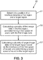
- the method 40 comprises at least the following steps:
- the determination of the position of the interface 34 can be based on a morphological image of the medium 14.
- the morphological image can be:
- the determination of the position of the interface 34 can be based on some of the sensed signals.
- a beamforming algorithm may be used to obtain image data of the medium 14 globally. These image data may then be processed to obtain the visual image 25 shown in Figure 2 . The image data are exploited to determine the position of the interface 34. Example of determination of the interface 34 using the image data will be provided below.
- a plurality of first image data associated with a first representative area 42 of the intermediate region 30 is calculated, and a first speed of sound c1 of the intermediate region 30 based on the plurality of first image data is determined.
- the first representative area 42 is chosen in one embodiment proximal to the interface 34.
- the first representative area 42 is typically a sub-area of the intermediate region 30.
- the first representative area 42 is taken as representative of the intermediate region 30, in so far as the speed of sound that is determined using the plurality of first image data is considered to be the speed of sound for the intermediate region 30, herein referred as the first speed of sound c1.
- Each of the first image data is determined based on a beamforming algorithm applied to at least the sensed signals corresponding to the first representative area 42 and which takes as a parameter a first reference speed of sound c_ref_1, and one of a plurality of first supposed speeds of sound c_supp_1.
- the first reference speed of sound c_ref_1 is for example a known speed of sound for the intermediate region 30.
- the value of the determined first speed of sound c1 is used.
- the position of the interface 34 is found by analyzing a gradient of the image data in the depth direction D. Because the density of the intermediate region 30 is substantially different from the one of the target region 12 (e.g. fatty tissues vs. liver), by analyzing the variation of the values of the image data in the depth direction D (and optionally in the surface direction D1) one may be able to determine, preferably automatically, the transition from the intermediate region 30 to the target region 12.
- the target region 12 e.g. fatty tissues vs. liver
- the position of the interface 34 is determined based on variations of amplitudes of image data of the medium 14 along the depth direction D between the intermediate region 30 and the target region 12.
- the variations of amplitudes of image data of the medium 14 along the depth direction D can be fitted to a parametric curve defining known evolution in such medium by any optimization algorithm.
- the parametric curve comprises several parameters, including for example the position of the interface 34 and other parameters.
- the image data may be in the form of a 2D matrix, and is determined based on the sensed signals and a beamforming algorithm which takes as a parameter a reference speed of sound c0.
- the reference speed of sound c0 may correspond to a typical value of the speed of sound for the medium 14, i.e. a global reference speed of sound c_ref_0.
- the position of the interface 34 is determined by an automatic image processing of the morphological image or any 2D image data corresponding to the medium.
- the automatic image processing may use a shape recognizing algorithm to determine the position of the interface 34.
- the automatic image processing may use a conventional contour detection filter to determine the position of the interface 34.
- a conventional contour detection filter is a Canny or a Gabor filter.
- image data are processed by a neural network that is trained with a plurality of classified image data of similar medium, said classified image data being indexed with physical characteristics of the medium, and said physical characteristics including the position of the interface in each of said classified image data.
- the above processing may be a deep learning method based on hundreds or thousands of classified image data.
- the position of the interface 34 could be arbitrarily chosen.
- the arbitrary choice of the position of the interface 34 could be made in function of known values of depth of the intermediate region 30. For example, it is standard that in a human body a layer of skin and fatty cell be 2 cm thick. In such case the position of the interface 34 will be chosen to be at a distance of 2 cm in the depth direction D relative to the outer surface 26.
- the position of the interface is chosen so that a ballistic echo is strong between the two regions separated by the interface 34.
- the position of the interface 34 is determined at an instant of time t i when a sensed signal or the phased sensed signals (beamformed signal) is maximum.
- the position of the interface may be solely a coordinate in the depth direction D, or coordinates in the depth direction D and the surface direction D1.
- the position of the interface 34 is preferably automatically determined in at least one of image data. Eventually, several image data are used (image data taken at various time instants), and the plurality of the determined positions are used to determine a best position, by for example a mean value of the successive determined positions of the interface 34.
- the first representative area 42 is chosen automatically by the processing unit 16 following a representative area selection algorithm.
- the first representative area 42 may be chosen to be a fixed portion of the intermediate region 30.
- the first representative area 42 may be chosen to be a rectangle of 1 cm width in the depth direction D and 2 cm long in the surface direction D1.
- the processing unit 16 may be advantageous to program the processing unit 16 to consider the first representative area 42 to be a rectangle of the visual image 25 located at, for example, 2 cm in the depth direction, and be midway of the image in the surface direction D1.
- the representative area 42 could be chosen in function of the image data globally. For example a quasi-homogeneous area of the intermediate region 30 may be chosen.
- the automatic selection allows obtaining a same result for the same data input. Additionally, the above steps may be performed once the patient data are collected, remotely in time and/or distance from the data collection, without need for his or her presence for additional scans.
- the determination of the first image data is based on at least some of the sensed signals and a beamforming algorithm, such as the one described above, and which takes as a parameter the first reference speed of sound c_ref_1.
- the first reference speed of sound c_ref_1 is a constant parameter which may be retrieved from a memory of the processing unit 16 and may correspond to classical values of the speed of sound in the medium 14. This value is independent from the sensed signals.
- corrections are to compensate the variation of speed of sound among the first supposed speeds of sound c_supp_1, so as first representative area 42 does not move in the intermediate region 30 and so as the excitation waves as plane waves have the same penetration angle ⁇ with respect to the surface direction D1. Thanks to these corrections, the produced first image data can be compared one to the other, and processed to calculate the first speed of sound c1 as explained.
- the first reference speed of sound c_ref_1 may correspond to a known value of the speed of sound globally in the medium 14. It may be equal to the reference speed of sound c0.
- the first reference speed of sound c_ref_1 may correspond to a known value of the speed of sound solely in the intermediate region 30. For example, it is known that the speed of sound in fatty tissues is about 1480 m/s.
- the first reference speed of sound c_ref_1 may alternatively correspond to a known value of the speed of sound solely in the region of interest 12. It is known that the speed of sound in the liver can be for example about 1540 m/s.
- the plurality of first supposed speeds of sound c_supp_1 may be various known values of the speed of sound in the medium 14 (e.g. medium 14 globally or intermediate region 30, or the target region 12) which form a range of possible referenced speeds of sound.
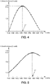
- the range of possible referenced speeds of sound can be a range between 1300 m/s and 1700 m/s, as shown on the abscissa of figure 4 .
- the first reference speed of sound c_ref_1 may be one of the plurality of first supposed speeds of sound c_supp_1.
- the first speed of sound c1 is calculated using a first focusing criterion.
- a plurality of first focusing values is obtained by applying the first focusing criterion to each of the plurality of first image data of the first representative area 42.
- the first speed of sound c1 is then a selected one of the plurality of respective first focusing values (i.e. the speed of sound corresponding to a selected first focusing value).
- the first speed of sound c1 is the maximum of the plurality of respective first focusing values.
- the first speed of sound c1 would be chosen as the maximum of the plurality of values obtained using the first coherence criterion applied to the plurality of first image data, i.e. for each supposed first speed of sound c_supp_1.
- Figure 4 shows an example of coherence values obtained using the plurality of first speed of sound c_supp_1 (the coherence values being each point of the graph, with the values on the ordinate axis and the corresponding supposed speed of sound used to obtain the coherence values being on the abscissa axis).
- the first speed of sound c1 is selected as the speed of sound corresponding to the maximum of the coherence values calculated.
- the maximum is the highest point of the bell shape graph, which is about 2.47 on the ordinate axis, and which corresponds to a speed of sound of 1460 m/s.
- the focusing criterion includes a resolution criterion, such as a maximum lateral resolution.
- the resolution of an ultrasonic image is improved when the beamforming focusing delays are accurately compensating the propagation time of flights. Therefore, using an estimation of the resolution in an ultrasound image (image data) can be used as a focusing criterion for estimating the speed of sound in the medium.
- a Fourier transform on image data corresponding to a vertical or lateral line of the first image data is used.
- the first focusing criterion can be the frequency bandwidth of frequency values obtained by the Fourier transform.
- the first speed of sound c1 would be chosen as the maximum of the plurality of values obtained using the first focusing criterion applied to the plurality of first image data, i.e. for each supposed first speed of sound c_supp_1.
- the first speed of sound c1 is chosen as the speed of sound that provides the greater frequency bandwidth for the frequency values obtained by the Fourier transform. This corresponds to having the best (maximum) resolution in the plurality of first image data.
- the resolution criterion is estimated by calculating a spatial autocorrelation of image data, and by estimating the size of spatial autocorrelation.
- Figure 7 shows an example of spatial autocorrelation of two dimension (2D) image data.
- This spatial autocorrelation is also a 2D surface having a peak at the center, i.e. coordinate (0, 0) in an axial and lateral lag.
- the spatial autocorrelation is represented as a plurality of level contour curves.
- a peak width can be derived in each of said direction.
- the width can be defined as the width of the peak shape curve for a height at half of the peak maximum (i.e. width at -6 dB).
- the size of the spatial autocorrelation is a function of said widths in each direction, and for example, it can be the maximum or mean value of the widths or determined by any other modulus function.
- the focusing criterion may include more than one criterion.
- the focusing criterion could include a coherence criterion and a maximum resolution criterion.
- the target representative area 44 is chosen automatically by the processing unit 16 in a similar way to the first representative area, yet applied to the target region 12.
- the target representative area 44 may be chosen to be a fixed portion of the target region 12.
- the target representative area 44 may be chosen to be a rectangle of 1 cm wide in the depth direction D and 2 cm long in the surface direction D1.
- the size and shape of the target representative area 44 may be different or the same as the one of the first representative area 42.
- the target representative area 44 may also be chosen to be at a fixed position on the visual image 25. Considering that the abdominal portion of the body has a muscle and connective tissues generally between 1 cm and 3 cm thick in the depth direction D, on human beings it may be advantageous to program the processing unit 16 to consider the target representative area 44 to be a rectangle of the visual image 25 located at, for example, 7 cm in the depth direction, and be midway of the image in the surface direction D1. In other embodiments, the target representative area 44 could be chosen in function of the image data globally. For example a quasi-homogeneous area of the target region 12 may be considered.
- the determination of the target image data that are associated with the target representative area 44 is based on at least some of the sensed signals and a beamforming algorithm, such as the one described above, and which takes as a parameter the target reference speed of sound c_ref_tar, the position of the interface 34, the first speed of sound c1 and a plurality of supposed target speeds of sound c_supp_tar.
- the target reference speed of sound c_ref_tar is for example a known speed of sound for the target region 12.
- the target reference speed of sound c_ref_tar is a constant parameter which may be retrieved from the memory of the processing unit 16 and which may correspond to classical values of the speed of sound in the medium 14. This value is independent from the sensed signals.
- This correction aims to compensate the variation of speed of sound among the supposed target speeds of sound c_supp_tar, so as target representative area 44 does not moves in the target region 12. Thanks to this, the produced target image data can be compared one to the other, and processed to calculate the target speed of sound c as explained above.
- the target reference speed of sound c_ref_tar may correspond to a known value of the average speed of sound globally in the medium 14 considered being homogenous. It may be set equal to the reference speed of sound c0 and/or to the first reference speed of sound c_ref_1.
- the target reference speed of sound c_ref_tar may correspond to a known value of the speed of sound solely in the intermediate region 30. For example, it is known that the speed of sound in fatty tissues is about 1480 m/s.
- the target reference speed of sound c_ref_tar may alternatively correspond to a known value of the speed of sound solely in the region of interest 12. For example, it is known that the speed of sound in the liver is about 1540 m/s.
- the plurality of supposed target speeds of sound c_supp_tar are various known values of the speed of sound (e.g. medium 14 globally, intermediate region 30, or target region 12) which form a range of possible reference speeds of sound.
- the plurality of supposed target speeds of sound c_supp_tar may be the same as the plurality of first supposed speeds of sound c_supp_1.
- the target reference speed of sound c_ref_tar may be one of the plurality of supposed target speeds of sound c_supp_tar.
- the target speed of sound cT is calculated using a focusing criterion similarly to the first speed of sound c1. As such, the detailed description of this step is very similar to that of the first step.
- a plurality of second focusing values is obtained by applying a target focusing criterion to each of the plurality of target image data of the target representative area 44.
- the target focusing criterion may be same or different as the first focusing criterion.
- the focusing criterion may include a coherence criterion and/or a maximum lateral resolution criterion.
- Each point of the graph corresponds to a coherence value (ordinate axis) obtained using one of the plurality of supposed speed of sound (abscissa axis) in the beamforming algorithm to obtain the first image data.
- the target speed of sound cT is selected as the speed of sound corresponding to the maximum of the plurality of coherence values calculated.
- the maximum is the highest point of the bell shape graph, which is about 0.55 on the ordinate axis, and which corresponding to a speed of sound of 1585 m/s.
- the beamforming algorithm can be refined by taking into account aberration delays D aberration .
- These aberration delays D aberration are arbitrary time of flights that are not due to the propagation of waves in the medium, and that are not taken into account by the propagation model, and therefore cannot be compensated by adjusting the parameters of the model such as the global speed of sound if an homogeneous model is chosen.
- These aberration delays can compensate delays in each physical transducers that can be slightly different one to another, delays in the electronic for signal amplifications, and delays in material layers in the probe.
- the method disclosed herewith determines at least a first speed of sound c1 and a target speed of sound cT.
- the method therefore builds a model of the medium having a plurality of speed of sounds (at least two) that minimize the amplitude of D aberration and therefore leads to a much more accurate estimation of the target speed of sound cT, which can very important in medical application, such as evaluation of hepatic steatosis or other disease.
- the intermediate region 30 may be segmented in one embodiment into two regions.
- a sub-interface 48 divides in the depth direction D the intermediate region 30 into a second region 50 of the intermediate region 30 proximal to the outer surface 26 and containing a second representative area 54 and a first region 52 of the intermediate region 30 proximal to the interface 34 and containing the first representative area 42.
- the sub-interface 48 could, for example, correspond to an interface between a skin layer and a muscle layer.
- the target speed of sound cT may then be determined based on the first speed of sound c1 as previously described, but the first speed of sound c1 would be determined based on a second speed of sound c2 of the second region 50.
- the target speed of sound cT in a medium segmented into a plurality of stacked region is calculated via the successive determination of adjacent stacked regions, from the most distal region to the target region 12, to the most proximal region to the target region 12.
- the method to determine the target speed of sound cT using a segmentation into three regions may be as follows:
- a method for determining the target speed of sound cT in the target region 12, according to a second embodiment, will be now described.
- This embodiment does not use the calculation of image data in representative areas. Instead the raw sensed signals S i are directly used for one predetermined location in the medium in each representative area. This embodiment may advantageously reduce the calculations to obtain the first and target speeds of sound.
- the medium 14 is segmented into the intermediate region 30 and the target region 12, using one of the ways described above.
- the first speed of sound c1 of the intermediate region 30 is determined directly based on at least some of the sensed signals.
- the determination of the first speed of sound c1 takes into account the first reference speed of sound c_ref_1, and one of the plurality of first supposed speeds of sound c_supp_1.
- the ratio C is a ratio between the coherent intensity and total incoherent intensity, and it satisfies the following inequality: 0 ⁇ C ⁇ 1
- This ratio C therefore represents a quality of the focusing functions that are applied for calculating the total travel of time, and it can be used as a first focusing criterion.
- the ratio C is then maximum (as represented on figure 4 ) if the first supposed speeds of sound c_supp_1 is the related to the best focusing functions, i.e. if the first supposed speeds of sound c_supp_1 is close to (ideally equal to) the first speed of sound c1.
- the target speed of sound cT is also determined inside the target region 12 directly based on at least some of the sensed signals.
- the determination of the target speed of sound cT takes into account the position of the interface 34, the target reference speed of sound c_ref_tar applied to the target region 12, the first speed of sound c1 applied to the intermediate region 30, and one of the plurality of supposed target speeds of sound c_supp_tar for the target region 12.
- the target focusing criterion is computed with the ratio C.
- This ratio C now takes into account the interface 34 and the first speed of sound c1 in the parameter ⁇ i that is the total travel time D for waves to reach the predetermined focused location and to travel back to a transducer. It is used as the target focusing criterion, and it has a maximum (as represented on figure 5 ) if the supposed target speed of sound is close to (ideally equal to) the target speed of sound cT.
- the ratio C considers sensed signals and summed of sensed signals that are time averaged via the brackets ⁇ > mathematical function, and that the ratio is calculated for a predetermined focused location (x, z) in the medium.
- the time averaging is replaced by an averaging over a plurality of focused locations.
- a method for determining the target speed of sound cT in the target region 12, according to a third embodiment, will be now described.
- This embodiment does not use the calculation of image data in representative areas. Instead the raw sensed signals Si are directly used for one predetermined focused location in the medium in each representative area. This embodiment may also reduce the calculations to obtain the first and target speeds of sound.
- the medium 14 is segmented into the intermediate region 30 and the target region 12, using one of the ways described above.
- the first speed of sound c1 of the intermediate region 30 is determined directly based on at least some of the sensed signals.
- the determination of the first speed of sound c1 takes into account the first reference speed of sound c_ref_1, and one of the plurality of first supposed speeds of sound c_supp_1.
- the first focusing criterion can be estimated by an integral of the spatial covariance R over the distance index n, and this integral is maximum if the first supposed speeds of sound c_supp_1 is the related to the best focusing functions, i.e. if the first supposed speeds of sound c_supp_1 is close to (ideally equal to) the first speed of sound c1.
- the target speed of sound cT is also determined inside the target region 12 directly based on at least some of the sensed signals.
- the determination of the target speed of sound cT takes into account the position of the interface 34, the target reference speed of sound c_ref_tar applied to the target region 12, the first speed of sound c1 applied to the intermediate region 30, and one of the plurality of supposed target speeds of sound c_supp_tar for the target region 12.
- the target focusing criterion is computed with the integral over distance index n of the above spatial covariance R. This calculation now takes into account the interface 34 and the first speed of sound c1 in the parameter the total travel time D for waves to reach the predetermined focused location and to travel back to the transducers. It is used as the target focusing criterion, and it has a maximum if the supposed target speed of sound is close to (ideally equal to) the target speed of sound cT.
- the above method 40 for determining the target speed of sound inside a target region of a medium is using an ultrasound imaging system.
- the method comprises a steps of determining a position of an interface in the medium, determining a first speed of sound of an intermediate region above the interface, and determining a target speed of sound inside a target region below the interface based on at least some of sensed signals and taking into account the position of the interface and the first speed of sound.
Landscapes
- Health & Medical Sciences (AREA)
- Life Sciences & Earth Sciences (AREA)
- Physics & Mathematics (AREA)
- Engineering & Computer Science (AREA)
- Pathology (AREA)
- General Health & Medical Sciences (AREA)
- Animal Behavior & Ethology (AREA)
- Veterinary Medicine (AREA)
- Nuclear Medicine, Radiotherapy & Molecular Imaging (AREA)
- Biomedical Technology (AREA)
- Heart & Thoracic Surgery (AREA)
- Medical Informatics (AREA)
- Molecular Biology (AREA)
- Surgery (AREA)
- Biophysics (AREA)
- Radiology & Medical Imaging (AREA)
- Public Health (AREA)
- General Physics & Mathematics (AREA)
- Radar, Positioning & Navigation (AREA)
- Remote Sensing (AREA)
- Computer Vision & Pattern Recognition (AREA)
- Acoustics & Sound (AREA)
- Vascular Medicine (AREA)
- Computer Networks & Wireless Communication (AREA)
- Physiology (AREA)
- Analytical Chemistry (AREA)
- Biochemistry (AREA)
- Immunology (AREA)
- Chemical & Material Sciences (AREA)
- Ultra Sonic Daignosis Equipment (AREA)
Claims (17)
- Procédé (40) de détermination d'une vitesse cible du son (cT) à l'intérieur d'une région cible (12) d'un milieu (14) utilisant un système d'imagerie par ultrasons (10) comprenant au moins une sonde (20) apte à détecter des ondes rétrodiffractées et à fournir des signaux détectés correspondant auxdites ondes rétrodiffractées à une unité de traitement (16) du système ultrasonore (10), le procédé (40) comprenant :- la détermination sur une image morphologique d'une position d'au moins une interface (42) dans le milieu (14), l'interface (34) divisant le milieu (14) en une région intermédiaire (30) du milieu (14) et de la région cible (12) dans une direction de profondeur (D),- la détermination d'une première vitesse du son (c1) de la région intermédiaire (30) sur la base d'au moins une partie des signaux détectés, et- la détermination de la vitesse cible du son (cT) à l'intérieur de la région cible (12) sur la base d'au moins une partie des signaux détectés et la prise en considération de la position de l'interface (34), et de la première vitesse du son (c1).
- Procédé selon la revendication 1, dans lequel la sonde (20) est apte à être fonctionnellement mise en contact avec une surface externe (32) du milieu (14), la sonde (20) étant apte à transmettre des ondes d'excitation dans le milieu (14) dans une direction de profondeur (D) vers la région cible (12), lesdites ondes d'excitation étant rétrodiffractées dans le milieu (14) vers la sonde (20), etdans lequel la première vitesse du son (c1) est déterminée en prenant en considération une première vitesse de référence du son (c ref 1), et l'une d'une pluralité de premières vitesses supposées du son (c_supp_1), etdans lequel la vitesse cible du son (cT) est déterminée en prenant en considération la position de l'interface (34), une vitesse de référence cible du son (c_ref_tar) appliquée à la région cible (12), la première vitesse du son (c1) appliquée à la région intermédiaire (30), et l'une d'une pluralité de vitesses cibles supposées du son (c_supp_tar) pour la région cible (12).
- Procédé selon la revendication 2, comprenant en outre le calcul d'une pluralité de premières données d'image associées à une première zone représentative (42) de la région intermédiaire (30) avant la détermination de la première vitesse du son (c1) de la région intermédiaire (30), la première vitesse du son étant basée sur la pluralité de premières données d'image, chacune des premières données d'images étant déterminée sur la base d'un algorithme de formation de faisceau appliqué au moins aux signaux détectés correspondant à la première zone représentative (42) et qui prend comme paramètre une première vitesse de référence du son (c ref 1), et l'une d'une pluralité de premières vitesses supposées du son (c_supp_1).
- Procédé selon l'une quelconque de la revendication 2 ou 3, comprenant en outre le calcul d'une pluralité de données d'images cibles associées à une zone cible représentative (44) de la région cible (12) avant la détermination de la vitesse cible du son (cT) à l'intérieur de la région cible (12), la vitesse cible du son (cT) étant basée sur la pluralité de données d'images cible dans la zone représentative (44) de la région cible (12), chacune des données d'image cibles étant déterminée sur la base d'un algorithme de formation de faisceau appliqué au moins aux signaux détectés correspondant à la zone représentative (44) et qui prend comme paramètres la position de l'interface (34), la vitesse cible de référence du son (c_ref_tar) appliquée à la région cible (12), la première vitesse du son (c1) appliquée à la région intermédiaire (30), et l'une de la pluralité de vitesses cibles supposées du son (c_supp_tar) pour la région cible (12).
- Procédé selon l'une quelconque des revendications 1 à 4, dans lequel au moins l'un parmi :- la pluralité de premières vitesses supposées du son (c_supp_1) et la pluralité de vitesses cibles supposées du son (c_supp_tar) ont une même valeur, et- les premières vitesses supposées du son (c_supp_1) sont des vitesses connues du son pour la région intermédiaire (30), et les vitesses cibles supposées du son (c_supp_tar) sont des vitesses connues du son pour la région cible (12).
- Procédé selon l'une quelconque des revendications 1 à 5, dans lequel la détermination de la position de l'interface (34) est basée sur au moins une partie des signaux détectés.
- Procédé selon l'une quelconque des revendications 1 à 5, dans lequel la détermination de la position de l'interface (34) est basée sur un traitement d'image automatique de l'image morphologique.
- Procédé selon l'une quelconque des revendications 1 à 6, dans lequel la position de l'interface (34) est déterminée sur la base de variations d'amplitudes de données d'image du milieu (14) le long de la direction de profondeur (D) entre la région intermédiaire (30) et la région cible (12), les données d'image étant déterminées sur la base des signaux détectés et d'un algorithme de formation de faisceaux qui prend comme paramètre la vitesse de référence du son (c0).
- Procédé selon l'une quelconque des revendications 1 à 8, dans lequel la première vitesse du son (c1) et/ou la vitesse cible du son (cT) sont chacune calculées à l'aide d'un premier critère de focalisation et/ou d'un critère de focalisation cible respectifs, une pluralité de premières valeurs de focalisation et/ou de valeurs de focalisation cibles respectives étant obtenues par application du premier critère de focalisation et/ou du critère de focalisation cible respectifs à, respectivement, la pluralité de premières données d'image de la première zone représentative (42) et/ou la pluralité de données d'image cibles de la zone cible représentative (44), la première vitesse du son (c1) étant une sélectionnée de la pluralité de premières valeurs de focalisation respectives et/ou la vitesse cible du son (cT) étant une sélectionnée de la pluralité de valeurs de focalisation cibles respectives.
- Procédé selon la revendication 9, dans lequel la première vitesse du son (c1) est le maximum de la pluralité de premières valeurs de focalisation respectives et/ou la vitesse cible du son (cT) est le maximum de la pluralité des valeurs de focalisation cibles respectives.
- Procédé selon la revendication 9 ou 10, dans lequel le critère de focalisation est un critère de cohérence.
- Procédé selon l'une quelconque des revendications 1 à 11, comprenant en outre :- la détermination d'une position d'une sous-interface dans la région intermédiaire (30), la sous-interface divisant dans la direction de la profondeur la région intermédiaire (30) en une seconde région de la région intermédiaire proximale de la surface externe et une première région de la région intermédiaire proximale de l'interface (34),- la détermination d'une seconde vitesse du son (c2) de la seconde région basée sur au moins une partie des signaux détectés en prenant comme paramètre une seconde vitesse de référence du son (c_ref_2), et l'une d'une pluralité de secondes vitesses supposées du son (c_supp_2),dans lequel
la détermination de la première vitesse du son (c1) est basée sur au moins une partie des signaux détectés et prend en considération la position de la sous-interface, la première vitesse de référence du son (c_ref_1) appliquée à la première région, la seconde vitesse de référence du son (c_ref_2) appliquée à la seconde région, et une l'une de la pluralité de premières vitesses supposées du son (c_supp_1) pour la première région. - Procédé selon la revendication 12, dans lequel la détermination de la position de la sous-interface est basée sur au moins une partie des signaux détectés.
- Procédé selon l'une quelconque des revendications 1 à 13, dans lequel la seconde région de la région intermédiaire contient la seconde zone représentative, et la première région de la région intermédiaire contient la première zone représentative.
- Procédé selon l'une quelconque des revendications 1 à 14, comprenant en outre le calcul d'une pluralité de secondes données d'image associées à une seconde zone représentative de la seconde région avant la détermination de la seconde vitesse du son (c2) de la seconde région basée sur la pluralité de secondes données d'image, chacune des secondes données d'image étant déterminée sur la base d'un algorithme de formation de faisceau au moins appliqué aux signaux détectés correspondant à la seconde zone représentative et qui prend comme paramètre une seconde vitesse de référence du son (c_ref_2), et l'une d'une pluralité de secondes vitesses supposées du son (c_supp_2).
- Procédé selon l'une quelconque des revendications 1 à 15, dans lequel le milieu (14) est un corps de mammifère et la surface externe (26) est la peau du mammifère, et
dans lequel la région cible (12) est le foie du mammifère, la région intermédiaire (30) est une région du milieu (14) compris entre le foie et la peau dans la direction de la profondeur (D). - Système d'imagerie par ultrasons (10) pour déterminer une vitesse cible du son (cT) à l'intérieur d'une région cible (12) d'un milieu (14), ledit système d'imagerie par ultrasons (10) comprenant :- une sonde (20) apte à être placée fonctionnellement en contact avec une surface externe (26) du milieu (14), la sonde (20) étant apte à transmettre des ondes d'excitation (21) dans le milieu (14) dans une direction de la profondeur (D) vers la région cible (12), lesdites ondes d'excitation (21) étant rétrodiffractées dans le milieu (14) vers la sonde (20), la sonde (20) étant apte à détecter les ondes rétrodiffractées (29) et à fournir des signaux détectés correspondant au système ultrasonore (10), et- une unité de traitement (16) mettant en œuvre le procédé selon l'une quelconque des revendications 1 à 16.
Priority Applications (5)
| Application Number | Priority Date | Filing Date | Title |
|---|---|---|---|
| EP18306309.8A EP3632330B1 (fr) | 2018-10-04 | 2018-10-04 | Procédé de détermination de la vitesse du son dans un milieu, système d'imagerie par ultrasons mettant en uvre ledit procédé |
| CN201980065286.2A CN112930144B (zh) | 2018-10-04 | 2019-10-01 | 用于确定介质中声速的方法、实施所述方法的超声成像系统 |
| PCT/EP2019/076544 WO2020070104A1 (fr) | 2018-10-04 | 2019-10-01 | Procédé de détermination d'une vitesse du son dans un milieu, un système d'imagerie ultrasonore mettant en œuvre ledit procédé |
| US17/281,693 US20220003717A1 (en) | 2018-10-04 | 2019-10-01 | A method for determining a speed of sound in a medium, an ultrasound imaging system implementing said method |
| KR1020217009911A KR102814482B1 (ko) | 2018-10-04 | 2019-10-01 | 매질 내 음속을 결정하는 방법, 상기 방법을 구현하는 초음파 이미징 시스템 |
Applications Claiming Priority (1)
| Application Number | Priority Date | Filing Date | Title |
|---|---|---|---|
| EP18306309.8A EP3632330B1 (fr) | 2018-10-04 | 2018-10-04 | Procédé de détermination de la vitesse du son dans un milieu, système d'imagerie par ultrasons mettant en uvre ledit procédé |
Publications (2)
| Publication Number | Publication Date |
|---|---|
| EP3632330A1 EP3632330A1 (fr) | 2020-04-08 |
| EP3632330B1 true EP3632330B1 (fr) | 2022-08-24 |
Family
ID=63857842
Family Applications (1)
| Application Number | Title | Priority Date | Filing Date |
|---|---|---|---|
| EP18306309.8A Active EP3632330B1 (fr) | 2018-10-04 | 2018-10-04 | Procédé de détermination de la vitesse du son dans un milieu, système d'imagerie par ultrasons mettant en uvre ledit procédé |
Country Status (5)
| Country | Link |
|---|---|
| US (1) | US20220003717A1 (fr) |
| EP (1) | EP3632330B1 (fr) |
| KR (1) | KR102814482B1 (fr) |
| CN (1) | CN112930144B (fr) |
| WO (1) | WO2020070104A1 (fr) |
Families Citing this family (8)
| Publication number | Priority date | Publication date | Assignee | Title |
|---|---|---|---|---|
| US20230265435A1 (en) | 2020-06-02 | 2023-08-24 | The Catholic University Of Korea Industry-Academic Cooperation Foundation | Composition comprising osteopontin inhibitor as active ingredient for prevention, alleviation, or treatment of neurodegenerative disease |
| CN112370073B (zh) * | 2020-10-12 | 2024-08-23 | 深圳华声医疗技术股份有限公司 | 超声声速校正方法、超声信号处理设备及存储介质 |
| JP7493481B2 (ja) * | 2021-04-27 | 2024-05-31 | 富士フイルムヘルスケア株式会社 | 超音波撮像装置 |
| FR3133304B1 (fr) * | 2022-03-10 | 2024-03-22 | E Scopics | Procede et dispositif d’estimation locale de la vitesse du son dans une region d’interet d’un milieu |
| EP4249952A1 (fr) | 2022-03-23 | 2023-09-27 | Supersonic Imagine | Procédé et système d'évaluation d'une vitesse supposée de propagation d'onde dans un milieu |
| US20240341734A1 (en) * | 2023-04-13 | 2024-10-17 | Medtronic Navigation, Inc. | Ultrasound Depth Calibration for Improving Navigational Accuracy |
| CN117129571B (zh) * | 2023-10-24 | 2024-02-13 | 自然资源部第二海洋研究所 | 一种海底沉积物力学与声学特性原位测量装置及方法 |
| CN120254759B (zh) * | 2025-04-02 | 2025-09-16 | 中国人民解放军91550部队 | 不规则海上布站的水声定位系统精度评估方法 |
Family Cites Families (13)
| Publication number | Priority date | Publication date | Assignee | Title |
|---|---|---|---|---|
| US8234923B2 (en) * | 2004-09-20 | 2012-08-07 | Innervision Medical Technologies Inc. | Systems and methods for ultrasound imaging |
| US9117439B2 (en) * | 2008-03-13 | 2015-08-25 | Supersonic Imagine | Method and apparatus for ultrasound synthetic imagining |
| JP5404141B2 (ja) * | 2008-06-13 | 2014-01-29 | キヤノン株式会社 | 超音波装置及びその制御方法 |
| US9668714B2 (en) * | 2010-04-14 | 2017-06-06 | Maui Imaging, Inc. | Systems and methods for improving ultrasound image quality by applying weighting factors |
| KR101140934B1 (ko) * | 2010-08-05 | 2012-05-03 | 삼성전기주식회사 | 초음파 영상의 음속도 추정 방법 및 이를 적용한 초음파 진단 장치 |
| KR20130080640A (ko) * | 2012-01-05 | 2013-07-15 | 삼성메디슨 주식회사 | 초음파 영상 제공 방법 및 초음파 영상 제공 장치 |
| KR101393512B1 (ko) * | 2012-07-25 | 2014-05-13 | 서강대학교산학협력단 | 초음파 속도를 추정하는 방법, 이를 이용한 초음파 영상 촬영 방법 및 장치 |
| JP6138596B2 (ja) * | 2013-06-05 | 2017-05-31 | 富士フイルム株式会社 | 超音波診断装置、超音波診断装置の作動方法およびプログラム |
| EP3040033A4 (fr) * | 2013-08-26 | 2017-05-10 | Hitachi, Ltd. | Appareil de diagnostic par ultrasons et procédé d'évaluation de l'élasticité |
| CN107405133B (zh) * | 2014-12-24 | 2021-06-08 | 声科影像有限公司 | 适用于各向异性介质成像的剪切波弹性成像方法及装置 |
| US10631775B2 (en) * | 2015-08-28 | 2020-04-28 | Wisconsin Alumni Research Foundation | Apparatus for dynamic stress measurement |
| BR112019002320A2 (pt) * | 2016-08-08 | 2019-06-18 | Koninklijke Philips Nv | sistema para medição de componentes de tecido corporal adiposo e magro, método para medição de componentes de tecido corporal adiposo e magro do tecido corporal, e programa de computador |
| US10799208B2 (en) * | 2016-11-04 | 2020-10-13 | Siemens Medical Solutions Usa, Inc. | Compressional sound speed imaging using ultrasound |
-
2018
- 2018-10-04 EP EP18306309.8A patent/EP3632330B1/fr active Active
-
2019
- 2019-10-01 KR KR1020217009911A patent/KR102814482B1/ko active Active
- 2019-10-01 CN CN201980065286.2A patent/CN112930144B/zh active Active
- 2019-10-01 WO PCT/EP2019/076544 patent/WO2020070104A1/fr not_active Ceased
- 2019-10-01 US US17/281,693 patent/US20220003717A1/en active Pending
Also Published As
| Publication number | Publication date |
|---|---|
| US20220003717A1 (en) | 2022-01-06 |
| CN112930144B (zh) | 2024-09-20 |
| KR20210069644A (ko) | 2021-06-11 |
| KR102814482B1 (ko) | 2025-05-29 |
| CN112930144A (zh) | 2021-06-08 |
| EP3632330A1 (fr) | 2020-04-08 |
| WO2020070104A1 (fr) | 2020-04-09 |
Similar Documents
| Publication | Publication Date | Title |
|---|---|---|
| EP3632330A1 (fr) | Procédé de détermination de la vitesse du son dans un milieu, système d'imagerie par ultrasons mettant en uvre ledit procédé | |
| US11523774B2 (en) | Tissue property estimation with ultrasound medical imaging | |
| US8801614B2 (en) | On-axis shear wave characterization with ultrasound | |
| US12048590B2 (en) | Liver disease activity estimation with ultrasound medical imaging | |
| US10324063B2 (en) | Methods and systems for measuring properties with ultrasound | |
| CN114176639A (zh) | 用于介质的超声表征的方法和系统 | |
| CN110785126A (zh) | 用于超声系统独立衰减系数估计的方法 | |
| EP3694418B1 (fr) | Imagerie par ondes de cisaillement ultrasonores avec génération d'ondes de cisaillement adaptatives en fonction du patient | |
| CN114176626A (zh) | 用于介质的超声表征的方法和系统 | |
| CN114176640A (zh) | 用于介质的超声表征的方法和系统 | |
| Wang et al. | Ultrasonic sound speed estimation for liver fat quantification: a review by the AIUM-RSNA QIBA pulse-echo quantitative ultrasound initiative | |
| US20090163812A1 (en) | Ultrasonographic Device And Ultrasonographic Method | |
| US20240293105A1 (en) | Liver disease activity estimation with ultrasound medical imaging | |
| JP2024523586A (ja) | エレベーション開口妨害の存在下での音響減衰係数の超音波定量化 | |
| Zhou et al. | Transcranial ultrafast ultrasound Doppler imaging: A phantom study | |
| CN113440166B (zh) | 利用超声医学成像的肝病活动估计 | |
| US12533112B2 (en) | Tissue property estimation with ultrasound medical imaging | |
| Gyöngy et al. | Variation of ultrasound image lateral spectrum with assumed speed of sound and true scatterer density | |
| CN114451914A (zh) | 用于物理量的超声导出替代物 | |
| Zhang et al. | Spatial Coherence-Based Sound Speed Estimation in Plane Wave Ultrasound Imaging | |
| US12616441B2 (en) | Fat fraction estimation from tissue non-linear response with ultrasound medical imaging | |
| HK40054287A (en) | A method for determining a speed of sound in a medium, an ultrasound imaging system implementing said method | |
| US20250331807A1 (en) | Quantitative ultrasound medical imaging enhanced by intervening tissue determination |
Legal Events
| Date | Code | Title | Description |
|---|---|---|---|
| PUAI | Public reference made under article 153(3) epc to a published international application that has entered the european phase |
Free format text: ORIGINAL CODE: 0009012 |
|
| STAA | Information on the status of an ep patent application or granted ep patent |
Free format text: STATUS: THE APPLICATION HAS BEEN PUBLISHED |
|
| AK | Designated contracting states |
Kind code of ref document: A1 Designated state(s): AL AT BE BG CH CY CZ DE DK EE ES FI FR GB GR HR HU IE IS IT LI LT LU LV MC MK MT NL NO PL PT RO RS SE SI SK SM TR |
|
| AX | Request for extension of the european patent |
Extension state: BA ME |
|
| STAA | Information on the status of an ep patent application or granted ep patent |
Free format text: STATUS: REQUEST FOR EXAMINATION WAS MADE |
|
| 17P | Request for examination filed |
Effective date: 20201007 |
|
| RBV | Designated contracting states (corrected) |
Designated state(s): AL AT BE BG CH CY CZ DE DK EE ES FI FR GB GR HR HU IE IS IT LI LT LU LV MC MK MT NL NO PL PT RO RS SE SI SK SM TR |
|
| GRAP | Despatch of communication of intention to grant a patent |
Free format text: ORIGINAL CODE: EPIDOSNIGR1 |
|
| STAA | Information on the status of an ep patent application or granted ep patent |
Free format text: STATUS: GRANT OF PATENT IS INTENDED |
|
| INTG | Intention to grant announced |
Effective date: 20220315 |
|
| GRAS | Grant fee paid |
Free format text: ORIGINAL CODE: EPIDOSNIGR3 |
|
| GRAA | (expected) grant |
Free format text: ORIGINAL CODE: 0009210 |
|
| STAA | Information on the status of an ep patent application or granted ep patent |
Free format text: STATUS: THE PATENT HAS BEEN GRANTED |
|
| AK | Designated contracting states |
Kind code of ref document: B1 Designated state(s): AL AT BE BG CH CY CZ DE DK EE ES FI FR GB GR HR HU IE IS IT LI LT LU LV MC MK MT NL NO PL PT RO RS SE SI SK SM TR |
|
| REG | Reference to a national code |
Ref country code: CH Ref legal event code: EP |
|
| REG | Reference to a national code |
Ref country code: DE Ref legal event code: R096 Ref document number: 602018039650 Country of ref document: DE |
|
| REG | Reference to a national code |
Ref country code: IE Ref legal event code: FG4D |
|
| REG | Reference to a national code |
Ref country code: AT Ref legal event code: REF Ref document number: 1513117 Country of ref document: AT Kind code of ref document: T Effective date: 20220915 |
|
| REG | Reference to a national code |
Ref country code: NL Ref legal event code: FP |
|
| REG | Reference to a national code |
Ref country code: LT Ref legal event code: MG9D |
|
| PG25 | Lapsed in a contracting state [announced via postgrant information from national office to epo] |
Ref country code: SE Free format text: LAPSE BECAUSE OF FAILURE TO SUBMIT A TRANSLATION OF THE DESCRIPTION OR TO PAY THE FEE WITHIN THE PRESCRIBED TIME-LIMIT Effective date: 20220824 Ref country code: RS Free format text: LAPSE BECAUSE OF FAILURE TO SUBMIT A TRANSLATION OF THE DESCRIPTION OR TO PAY THE FEE WITHIN THE PRESCRIBED TIME-LIMIT Effective date: 20220824 Ref country code: PT Free format text: LAPSE BECAUSE OF FAILURE TO SUBMIT A TRANSLATION OF THE DESCRIPTION OR TO PAY THE FEE WITHIN THE PRESCRIBED TIME-LIMIT Effective date: 20221226 Ref country code: NO Free format text: LAPSE BECAUSE OF FAILURE TO SUBMIT A TRANSLATION OF THE DESCRIPTION OR TO PAY THE FEE WITHIN THE PRESCRIBED TIME-LIMIT Effective date: 20221124 Ref country code: LV Free format text: LAPSE BECAUSE OF FAILURE TO SUBMIT A TRANSLATION OF THE DESCRIPTION OR TO PAY THE FEE WITHIN THE PRESCRIBED TIME-LIMIT Effective date: 20220824 Ref country code: LT Free format text: LAPSE BECAUSE OF FAILURE TO SUBMIT A TRANSLATION OF THE DESCRIPTION OR TO PAY THE FEE WITHIN THE PRESCRIBED TIME-LIMIT Effective date: 20220824 Ref country code: FI Free format text: LAPSE BECAUSE OF FAILURE TO SUBMIT A TRANSLATION OF THE DESCRIPTION OR TO PAY THE FEE WITHIN THE PRESCRIBED TIME-LIMIT Effective date: 20220824 |
|
| REG | Reference to a national code |
Ref country code: AT Ref legal event code: MK05 Ref document number: 1513117 Country of ref document: AT Kind code of ref document: T Effective date: 20220824 |
|
| PG25 | Lapsed in a contracting state [announced via postgrant information from national office to epo] |
Ref country code: PL Free format text: LAPSE BECAUSE OF FAILURE TO SUBMIT A TRANSLATION OF THE DESCRIPTION OR TO PAY THE FEE WITHIN THE PRESCRIBED TIME-LIMIT Effective date: 20220824 Ref country code: IS Free format text: LAPSE BECAUSE OF FAILURE TO SUBMIT A TRANSLATION OF THE DESCRIPTION OR TO PAY THE FEE WITHIN THE PRESCRIBED TIME-LIMIT Effective date: 20221224 Ref country code: HR Free format text: LAPSE BECAUSE OF FAILURE TO SUBMIT A TRANSLATION OF THE DESCRIPTION OR TO PAY THE FEE WITHIN THE PRESCRIBED TIME-LIMIT Effective date: 20220824 Ref country code: GR Free format text: LAPSE BECAUSE OF FAILURE TO SUBMIT A TRANSLATION OF THE DESCRIPTION OR TO PAY THE FEE WITHIN THE PRESCRIBED TIME-LIMIT Effective date: 20221125 |
|
| PG25 | Lapsed in a contracting state [announced via postgrant information from national office to epo] |
Ref country code: SM Free format text: LAPSE BECAUSE OF FAILURE TO SUBMIT A TRANSLATION OF THE DESCRIPTION OR TO PAY THE FEE WITHIN THE PRESCRIBED TIME-LIMIT Effective date: 20220824 Ref country code: RO Free format text: LAPSE BECAUSE OF FAILURE TO SUBMIT A TRANSLATION OF THE DESCRIPTION OR TO PAY THE FEE WITHIN THE PRESCRIBED TIME-LIMIT Effective date: 20220824 Ref country code: ES Free format text: LAPSE BECAUSE OF FAILURE TO SUBMIT A TRANSLATION OF THE DESCRIPTION OR TO PAY THE FEE WITHIN THE PRESCRIBED TIME-LIMIT Effective date: 20220824 Ref country code: DK Free format text: LAPSE BECAUSE OF FAILURE TO SUBMIT A TRANSLATION OF THE DESCRIPTION OR TO PAY THE FEE WITHIN THE PRESCRIBED TIME-LIMIT Effective date: 20220824 Ref country code: CZ Free format text: LAPSE BECAUSE OF FAILURE TO SUBMIT A TRANSLATION OF THE DESCRIPTION OR TO PAY THE FEE WITHIN THE PRESCRIBED TIME-LIMIT Effective date: 20220824 Ref country code: AT Free format text: LAPSE BECAUSE OF FAILURE TO SUBMIT A TRANSLATION OF THE DESCRIPTION OR TO PAY THE FEE WITHIN THE PRESCRIBED TIME-LIMIT Effective date: 20220824 |
|
| REG | Reference to a national code |
Ref country code: DE Ref legal event code: R097 Ref document number: 602018039650 Country of ref document: DE |
|
| PG25 | Lapsed in a contracting state [announced via postgrant information from national office to epo] |
Ref country code: SK Free format text: LAPSE BECAUSE OF FAILURE TO SUBMIT A TRANSLATION OF THE DESCRIPTION OR TO PAY THE FEE WITHIN THE PRESCRIBED TIME-LIMIT Effective date: 20220824 Ref country code: MC Free format text: LAPSE BECAUSE OF FAILURE TO SUBMIT A TRANSLATION OF THE DESCRIPTION OR TO PAY THE FEE WITHIN THE PRESCRIBED TIME-LIMIT Effective date: 20220824 Ref country code: EE Free format text: LAPSE BECAUSE OF FAILURE TO SUBMIT A TRANSLATION OF THE DESCRIPTION OR TO PAY THE FEE WITHIN THE PRESCRIBED TIME-LIMIT Effective date: 20220824 |
|
| REG | Reference to a national code |
Ref country code: CH Ref legal event code: PL |
|
| REG | Reference to a national code |
Ref country code: BE Ref legal event code: MM Effective date: 20221031 |
|
| PG25 | Lapsed in a contracting state [announced via postgrant information from national office to epo] |
Ref country code: AL Free format text: LAPSE BECAUSE OF FAILURE TO SUBMIT A TRANSLATION OF THE DESCRIPTION OR TO PAY THE FEE WITHIN THE PRESCRIBED TIME-LIMIT Effective date: 20220824 Ref country code: LU Free format text: LAPSE BECAUSE OF NON-PAYMENT OF DUE FEES Effective date: 20221004 |
|
| PLBE | No opposition filed within time limit |
Free format text: ORIGINAL CODE: 0009261 |
|
| STAA | Information on the status of an ep patent application or granted ep patent |
Free format text: STATUS: NO OPPOSITION FILED WITHIN TIME LIMIT |
|
| PG25 | Lapsed in a contracting state [announced via postgrant information from national office to epo] |
Ref country code: LI Free format text: LAPSE BECAUSE OF NON-PAYMENT OF DUE FEES Effective date: 20221031 Ref country code: CH Free format text: LAPSE BECAUSE OF NON-PAYMENT OF DUE FEES Effective date: 20221031 |
|
| 26N | No opposition filed |
Effective date: 20230525 |
|
| PG25 | Lapsed in a contracting state [announced via postgrant information from national office to epo] |
Ref country code: SI Free format text: LAPSE BECAUSE OF FAILURE TO SUBMIT A TRANSLATION OF THE DESCRIPTION OR TO PAY THE FEE WITHIN THE PRESCRIBED TIME-LIMIT Effective date: 20220824 |
|
| PG25 | Lapsed in a contracting state [announced via postgrant information from national office to epo] |
Ref country code: BE Free format text: LAPSE BECAUSE OF NON-PAYMENT OF DUE FEES Effective date: 20221031 |
|
| PG25 | Lapsed in a contracting state [announced via postgrant information from national office to epo] |
Ref country code: IE Free format text: LAPSE BECAUSE OF NON-PAYMENT OF DUE FEES Effective date: 20221004 |
|
| PG25 | Lapsed in a contracting state [announced via postgrant information from national office to epo] |
Ref country code: HU Free format text: LAPSE BECAUSE OF FAILURE TO SUBMIT A TRANSLATION OF THE DESCRIPTION OR TO PAY THE FEE WITHIN THE PRESCRIBED TIME-LIMIT; INVALID AB INITIO Effective date: 20181004 |
|
| PG25 | Lapsed in a contracting state [announced via postgrant information from national office to epo] |
Ref country code: CY Free format text: LAPSE BECAUSE OF FAILURE TO SUBMIT A TRANSLATION OF THE DESCRIPTION OR TO PAY THE FEE WITHIN THE PRESCRIBED TIME-LIMIT Effective date: 20220824 |
|
| PG25 | Lapsed in a contracting state [announced via postgrant information from national office to epo] |
Ref country code: MK Free format text: LAPSE BECAUSE OF FAILURE TO SUBMIT A TRANSLATION OF THE DESCRIPTION OR TO PAY THE FEE WITHIN THE PRESCRIBED TIME-LIMIT Effective date: 20220824 |
|
| PG25 | Lapsed in a contracting state [announced via postgrant information from national office to epo] |
Ref country code: TR Free format text: LAPSE BECAUSE OF FAILURE TO SUBMIT A TRANSLATION OF THE DESCRIPTION OR TO PAY THE FEE WITHIN THE PRESCRIBED TIME-LIMIT Effective date: 20220824 |
|
| PG25 | Lapsed in a contracting state [announced via postgrant information from national office to epo] |
Ref country code: BG Free format text: LAPSE BECAUSE OF FAILURE TO SUBMIT A TRANSLATION OF THE DESCRIPTION OR TO PAY THE FEE WITHIN THE PRESCRIBED TIME-LIMIT Effective date: 20220824 |
|
| PG25 | Lapsed in a contracting state [announced via postgrant information from national office to epo] |
Ref country code: MT Free format text: LAPSE BECAUSE OF FAILURE TO SUBMIT A TRANSLATION OF THE DESCRIPTION OR TO PAY THE FEE WITHIN THE PRESCRIBED TIME-LIMIT Effective date: 20220824 |
|
| PGFP | Annual fee paid to national office [announced via postgrant information from national office to epo] |
Ref country code: GB Payment date: 20240919 Year of fee payment: 7 |
|
| PGFP | Annual fee paid to national office [announced via postgrant information from national office to epo] |
Ref country code: FR Payment date: 20240919 Year of fee payment: 7 |
|
| PGFP | Annual fee paid to national office [announced via postgrant information from national office to epo] |
Ref country code: NL Payment date: 20240919 Year of fee payment: 7 |
|
| PGFP | Annual fee paid to national office [announced via postgrant information from national office to epo] |
Ref country code: IT Payment date: 20240919 Year of fee payment: 7 |
|
| PGFP | Annual fee paid to national office [announced via postgrant information from national office to epo] |
Ref country code: DE Payment date: 20240919 Year of fee payment: 7 |
|
| REG | Reference to a national code |
Ref country code: DE Ref legal event code: R082 Ref document number: 602018039650 Country of ref document: DE Representative=s name: PLASSERAUD IP GMBH, DE |